28
1 LHCb Computing Umberto Marconi On behalf of the Bologna Group Castiadas, May 27, 2004
| Date post: | 01-Jan-2016 |
| Category: |
Documents |
| Upload: | arthur-harris |
| View: | 36 times |
| Download: | 2 times |
1
LHCb Computing
Umberto Marconi
On behalf of the Bologna GroupCastiadas, May 27, 2004
U. MarconiINFN, Bologna
2
Overview
■ Introduction■ The LHCb experiment■ Computing Activities
●Online
●Offline
U. MarconiINFN, Bologna
3
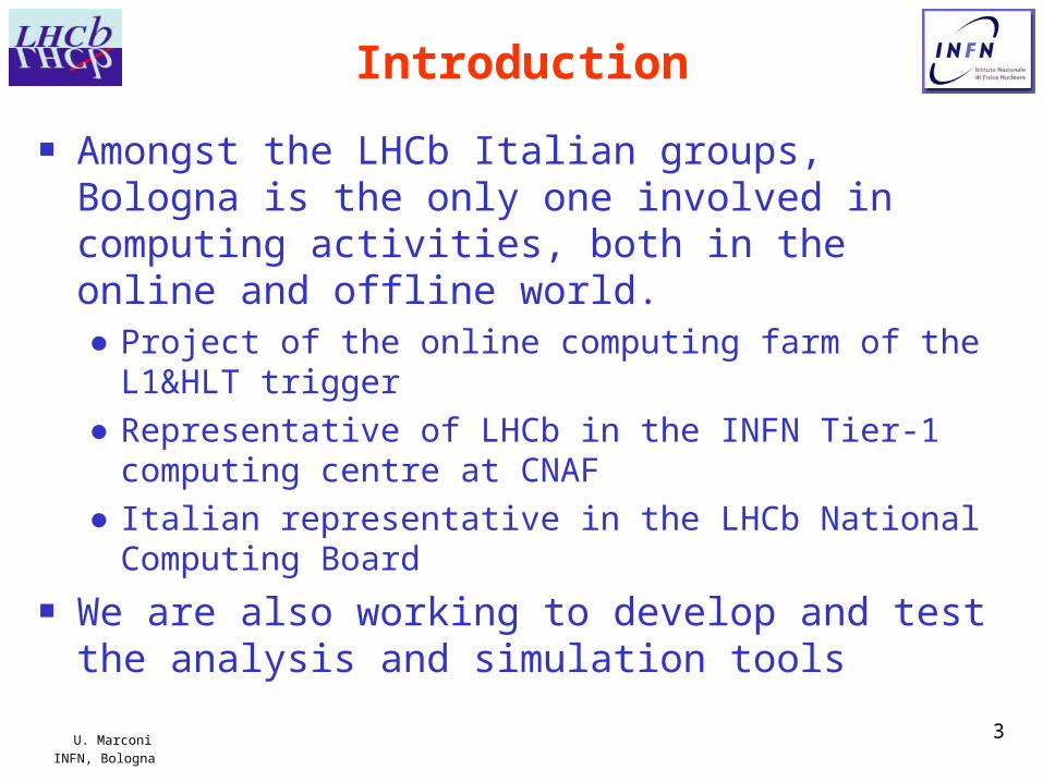
Introduction
■ Amongst the LHCb Italian groups, Bologna is the only one involved in computing activities, both in the online and offline world.● Project of the online computing farm of the L1&HLT
trigger● Representative of LHCb in the INFN Tier-1 computing
centre at CNAF● Italian representative in the LHCb National Computing
Board
■ We are also working to develop and test the analysis and simulation tools

U. MarconiINFN, Bologna
4
Beauty Physics at LHCb
■ Aim of LHCb is to study the dynamics of the beauty quark, with the main goal of measuring the CP symmetry violation in this sector.
■ The proton-proton collisions at 14TeV, at the frequency of 40 MHz, of LHC, can be exploited as intense source of beauty quarks● The expected intensity of beauty production is of about 0.1 MHz● The signal to noise ratio at the source is expected of the order of
1/160■ Useful processes are those related to the oscillations
and decays of the Bd and Bs neutral mesons ● A “rare decay process” is a decay mode whose probabilities is
of the order or below 10-4
■ The intensity of the interesting processes are expected at the level or below
0.1MHz x 10-4 = 10Hz
U. MarconiINFN, Bologna
5
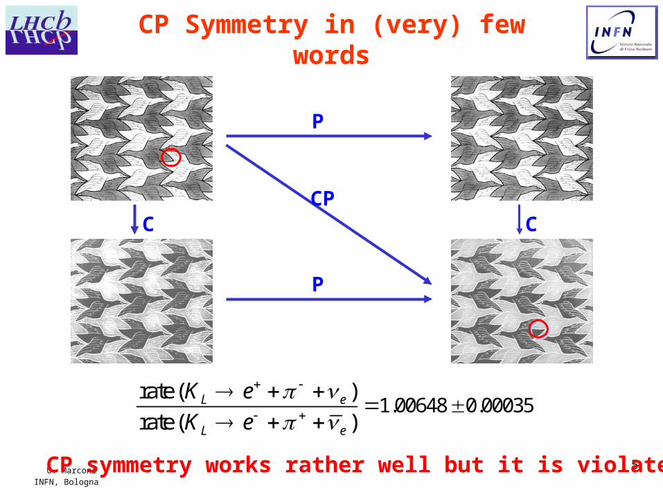
CP Symmetry in (very) few words
CP symmetry works rather well but it is violated
P
C
P
CCP
1.00648 0.00035rate ( )
rate ( )L e
L e
K e
K e
U. MarconiINFN, Bologna
6
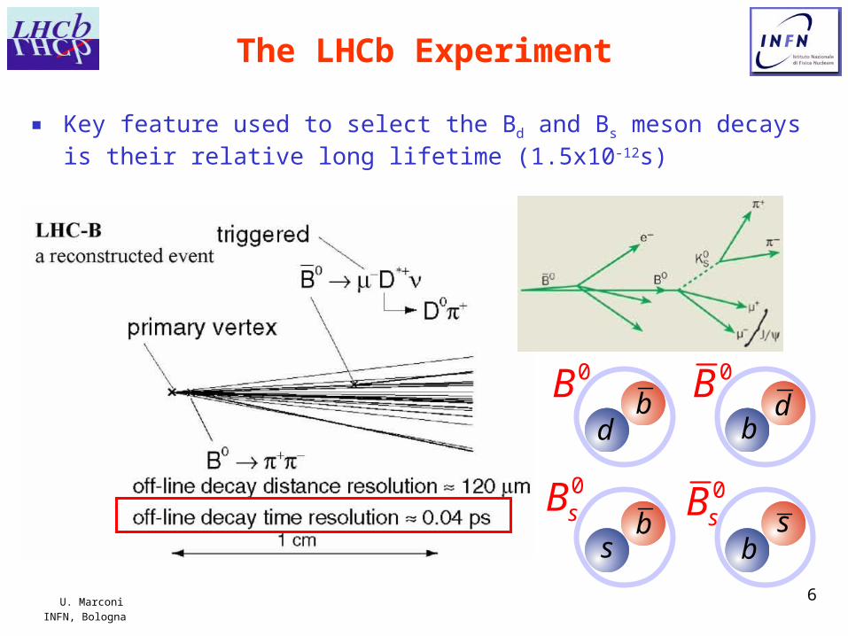
The LHCb Experiment
■ Key feature used to select the Bd and Bs meson decays is their relative long lifetime (1.5x10⁻¹²s)
0Bb
d
0Bbd
0sB bs
0sBbs
U. MarconiINFN, Bologna
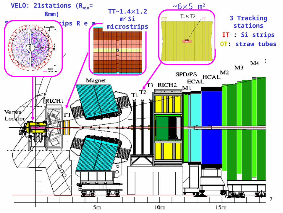
7
VELO: 21stations (Rmin= 8mm)
Si 220 mm, strips R e φ TT~1.41.2 m2
Si microstrips
~65 m2
3 Tracking stations
IT : Si strips
OT: straw tubes
U. MarconiINFN, Bologna
8
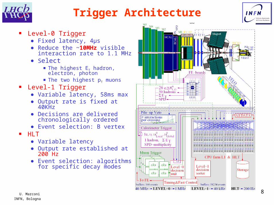
Trigger Architecture
■ Level-0 Trigger ● Fixed latency, 4μs ● Reduce the ~10MHz visible
interaction rate to 1.1 MHz● Select
▪ The highest ET hadron, electron, photon
▪ The two highest pT muons■ Level-1 Trigger
● Variable latency, 58ms max● Output rate is fixed at 40KHz● Decisions are delivered
chronologically ordered● Event selection: B vertex
■ HLT ● Variable latency● Output rate established at
200 Hz● Event selection: algorithms
for specific decay modes
U. MarconiINFN, Bologna
9
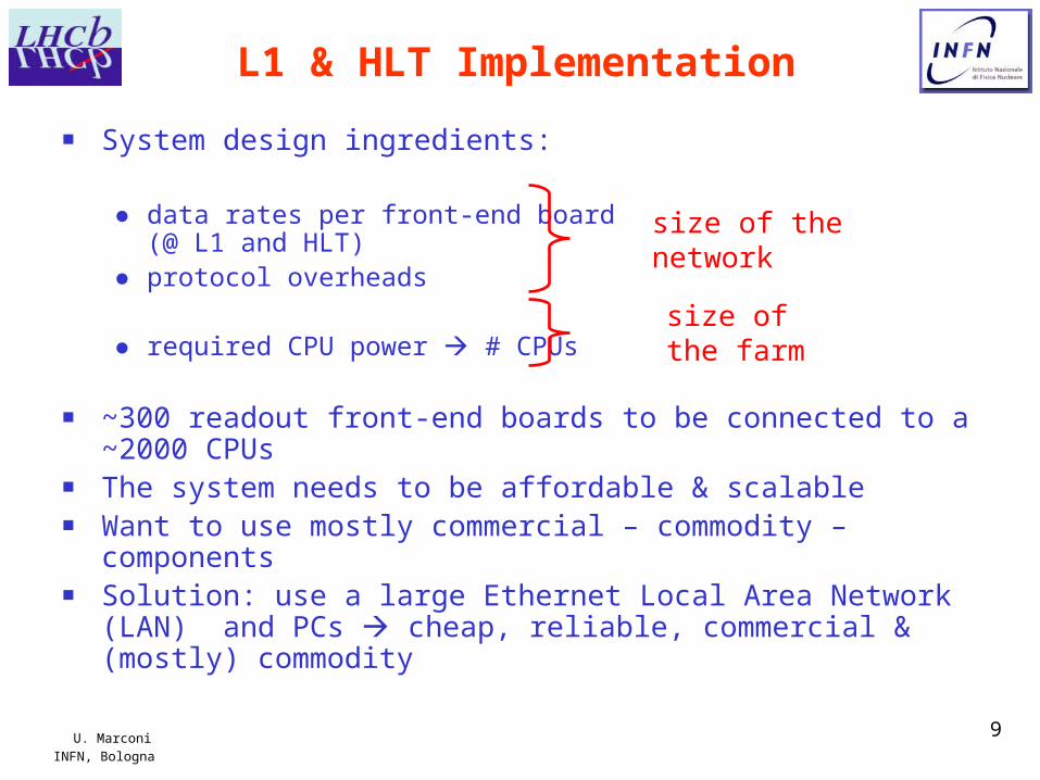
L1 & HLT Implementation
■ System design ingredients:
● data rates per front-end board (@ L1 and HLT)
● protocol overheads
● required CPU power # CPUs
■ ~300 readout front-end boards to be connected to a ~2000 CPUs ■ The system needs to be affordable & scalable ■ Want to use mostly commercial – commodity – components ■ Solution: use a large Ethernet Local Area Network (LAN) and PCs
cheap, reliable, commercial & (mostly) commodity
size of thenetwork
size of the farm
U. MarconiINFN, Bologna
10
Key Features
■ Push-through protocol simple, scalable
■ Distributed global flow-control (throttle) via Timing and Fast Control (TFC) system disable trigger temporarily to avoid buffer overflows
■ Data are sent as IP packets can be used with any standard network equipment
■ Data for several consecutive triggers are packed into Multi Event Packets and sent as a single packet over the network reduces packet rate and transport overheads
■ CPU-farm is partitioned into sub-farms reduces the connectivity problem
■ Sub-farms are assigned centrally by the TFC system central static load balancing
■ Event-building and dynamic load-balancing is done by the Subfarm Controller (SFC)
■ Single CPU farm is used for both L1 & HLT. L1 runs as a priority task, HLT in the back-ground on each node minimises latency for L1 and overall idle time, seamless redistribution of computing power
U. MarconiINFN, Bologna
11
L1 Event-Building
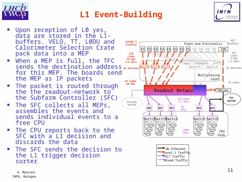
■ Upon reception of L0 yes, data are stored in the L1-buffers. VELO, TT, L0DU and Calorimeter Selection Crate pack data into a MEP
■ When a MEP is full, the TFC sends the destination address for this MEP. The boards send the MEP as IP packets
■ The packet is routed through the the readout-network to the Subfarm Controller (SFC)
■ The SFC collects all MEPs, assembles the events and sends individual events to a free CPU
■ The CPU reports back to the SFC with a L1 decision and discards the data
■ The SFC sends the decision to the L1 trigger decision sorter
MultiplexingLayer
FE FE FE FE FE FE FE FE FE FE FE FE
Switch Switch
Level-1Traffic
HLTTraffic
126Links
44 kHz5.5 GB/s
323Links4 kHz
1.6 GB/s
29 Switches
32 Links
94 SFCs
Front-end Electronics
Level-1 Traffic
Mixed Traffic
Gb Ethernet
HLT Traffic
94 Links7.1 GB/s
TRM
Sorter
TFCSystem
L1-Decision
StorageSystem
Readout Network
Switch Switch Switch
SFC
Switch
CPU
CPU
CPU
SFC
Switch
CPU
CPU
CPU
SFC
Switch
CPU
CPU
CPU
SFC
Switch
CPU
CPU
CPU
SFC
Switch
CPU
CPU
CPU
CPUFarm
62 Switches
64 Links88 kHz
~1800 CPUs
U. MarconiINFN, Bologna
12
HLT Event-Building
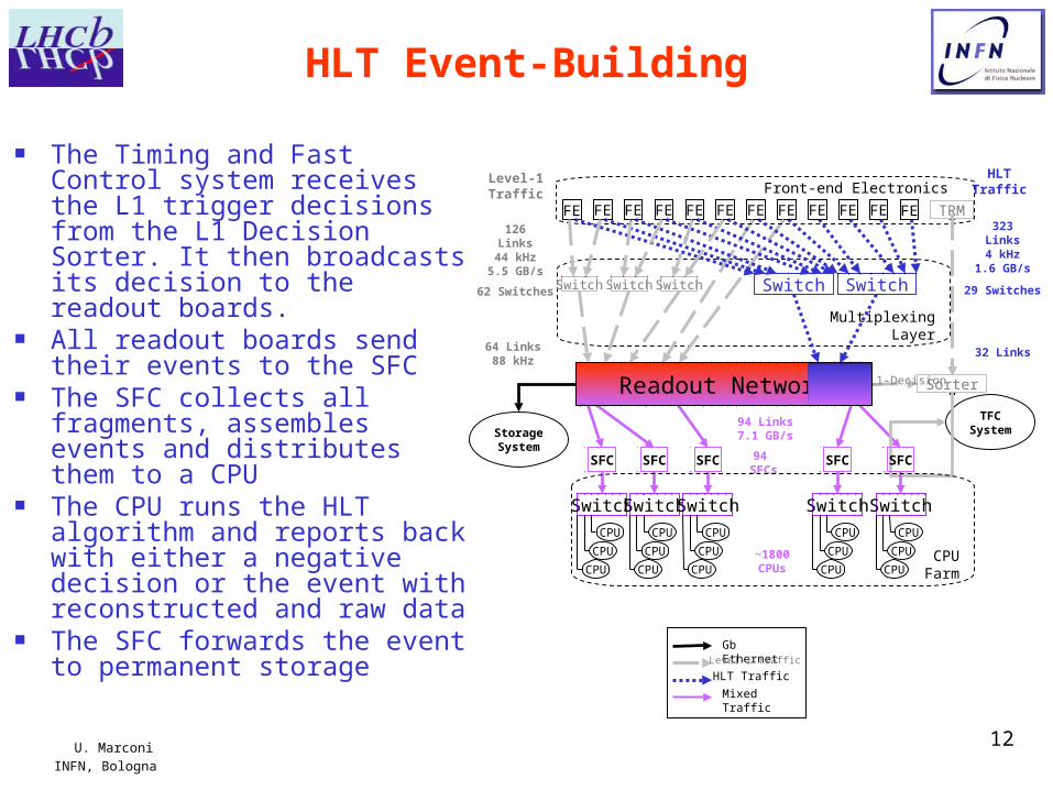
■ The Timing and Fast Control system receives the L1 trigger decisions from the L1 Decision Sorter. It then broadcasts its decision to the readout boards.
■ All readout boards send their events to the SFC
■ The SFC collects all fragments, assembles events and distributes them to a CPU
■ The CPU runs the HLT algorithm and reports back with either a negative decision or the event with reconstructed and raw data
■ The SFC forwards the event to permanent storage Gb Ethernet
Level-1 Traffic
Mixed Traffic
HLT Traffic
MultiplexingLayer
FE FE FE FE FE FE FE FE FE FE FE FE
Switch Switch
Level-1Traffic
HLTTraffic
126Links44 kHz
5.5 GB/s
323Links4 kHz
1.6 GB/s
29 Switches
32 Links
94 SFCs
Front-end Electronics
94 Links7.1 GB/s
TRM
Sorter
TFCSystem
L1-Decision
StorageSystem
Readout Network
Switch Switch Switch
SFC
Switch
CPU
CPU
CPU
SFC
Switch
CPU
CPU
CPU
SFC
Switch
CPU
CPU
CPU
SFC
Switch
CPU
CPU
CPU
SFC
Switch
CPU
CPU
CPU
CPUFarm
62 Switches
64 Links88 kHz
~1800 CPUs
U. MarconiINFN, Bologna
13
Front-end Electronics
CPUFarm
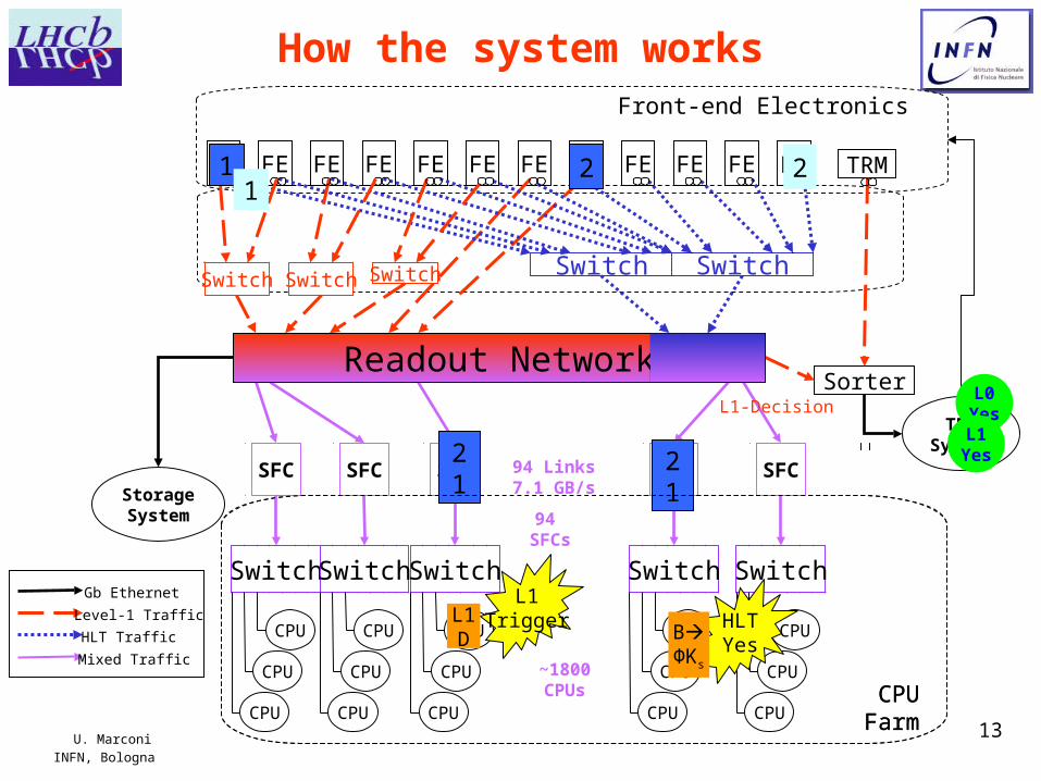
How the system works
FE FE FE FE FE FE FE FE FE FE FE FE
Switch Switch
94 SFCs
Gb Ethernet
Level-1 Traffic
Mixed Traffic
HLT Traffic
94 Links7.1 GB/s
TRM
Sorter
TFCSystem
L1-Decision
StorageSystem
Readout Network
Switch Switch Switch
SFC
Switch
CPU
CPU
CPU
SFC
Switch
CPU
CPU
CPU
SFC
Switch
CPU
CPU
CPU
SFC
Switch
CPU
CPU
CPU
SFC
Switch
CPU
CPU
CPU
~1800 CPUs
1
21
L0Yes
2
L1TriggerL1
D
L1Yes
12
21
HLTYes
BΦΚs
CPUFarm
U. MarconiINFN, Bologna
14
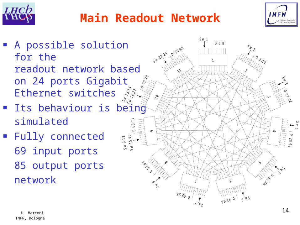
Main Readout Network
■ A possible solution for the readout network based on 24 ports Gigabit Ethernet switches
■ Its behaviour is being simulated
■ Fully connected
69 input ports
85 output ports
network
1
58
67
211
10
349
D 1:8
D 9:16
Sw 1
Sw 2
D 17:24
Sw
3
Sw
4D
25:32
Sw
18:
22
D 7
2:78
Sw 23:24 D 79:85
Sw
15:
17D
65:
71
Sw 8
D 33:40
D 57:6
4
Sw 5Sw 7
Sw 6D 49:56D 41:48
Sw
9:1
2S
w 1
3 :14
U. MarconiINFN, Bologna
15
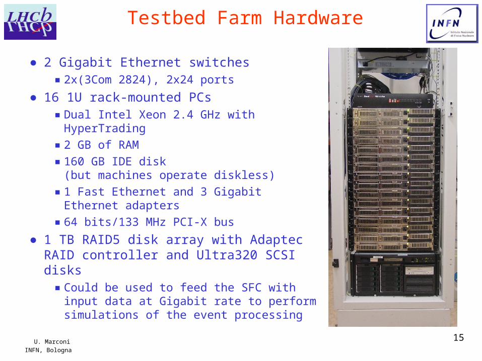
Testbed Farm Hardware
● 2 Gigabit Ethernet switches
▪ 2x(3Com 2824), 2x24 ports
● 16 1U rack-mounted PCs
▪ Dual Intel Xeon 2.4 GHz with HyperTrading
▪ 2 GB of RAM
▪ 160 GB IDE disk(but machines operate diskless)
▪ 1 Fast Ethernet and 3 Gigabit Ethernet adapters
▪ 64 bits/133 MHz PCI-X bus
● 1 TB RAID5 disk array with Adaptec RAID controller and Ultra320 SCSI disks
▪ Could be used to feed the SFC with input data at Gigabit rate to perform simulations of the event processing
U. MarconiINFN, Bologna
16
Farm Configuration
■ 16 Nodes running Red Hat 9b, with 2.6.5 kernel● 1 Gateway, acting as bastion host and NAT to the external network● 1 Service PC, providing network boot services, central syslog, time
synchronization, NFS exports, etc.● 1 diskless SFC, with 3 Gigabit links (2 for data and 1 for control traffic)● 13 diskless SFNs (26 physical, 52 logical processors with HT) with 2
Gigabit links (1 for data and 1 for control traffic)■ Root fs mounted on a 150 MB RAM disk (kernel and
compressed RAM disk image download from network at boot time)● RAM disk is automatically created by a set of scripts on admin’s demand
whenever a change is performed on a development root fs area on the service PC, and put online for subsequent reboots
■ /usr and /home mounted via NFS from the service PC● NFS mount points can provide access to the online application binaries
U. MarconiINFN, Bologna
17
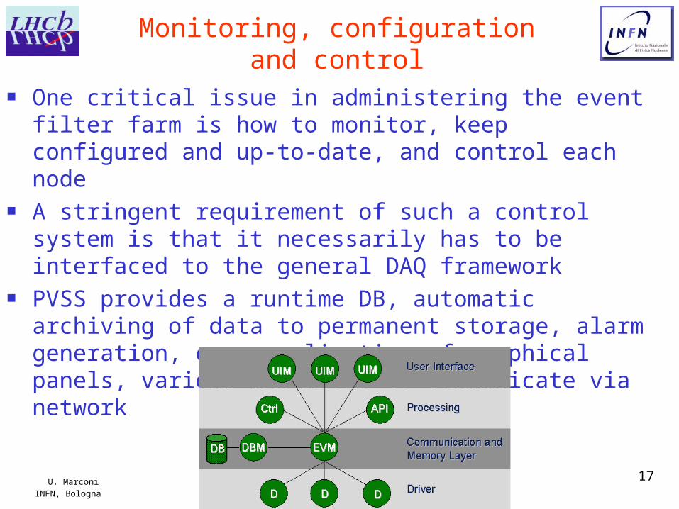
Monitoring, configuration and control
■ One critical issue in administering the event filter farm is how to monitor, keep configured and up-to-date, and control each node
■ A stringent requirement of such a control system is that it necessarily has to be interfaced to the general DAQ framework
■ PVSS provides a runtime DB, automatic archiving of data to permanent storage, alarm generation, easy realization of graphical panels, various protocols to communicate via network
U. MarconiINFN, Bologna
18
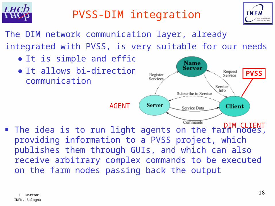
PVSS-DIM integration
The DIM network communication layer, already
integrated with PVSS, is very suitable for our needs● It is simple and efficient● It allows bi-directional
communication
■ The idea is to run light agents on the farm nodes, providing information to a PVSS project, which publishes them through GUIs, and which can also receive arbitrary complex commands to be executed on the farm nodes passing back the output
PVSS
DIM CLIENT
AGENT
U. MarconiINFN, Bologna
19
Monitoring■ All the relevant quantities useful to diagnose hardware or
configuration problems should be traced● CPU fans and temperatures● Memory occupancy● RAM disk filesystem occupancy● CPU load● Network interface statistics, counters, errors● TCP/IP stack counters● Status of relevant processes● Network Switch statistics (via the SNMP-PVSS interface)● … plus many other things to be learnt by experience
■ Information should be viewed as actual values and/or historical trends
■ Alarms should be issued whenever relevant quantities don’t fit in allowed ranges● PVSS naturally allows it, and can even start feedback procedures
U. MarconiINFN, Bologna
20
Configuration and control
■ The idea is to embed in the framework every common operation which is usually needed by the sysadm, to be performed by means of GUIs
■ On the Service PCs side● Upgrade of operating systems
▪ RAM disk creation, kernel upgrades, etc.
● Upgrade of application software
▪ Put online new versions of online programs, utilities, upgrade of bugged packages,…
● Automatic setup of configuration files
▪ dhcpd table, NFS exports table, etc.
■ On the farm nodes side● Inspection and modification of files
● Broadcast commands to the entire farm (e.g., reboot)
● Fast logon by means of a shell like environment embedded inside a PVSS GUI (e.g., commands, stdout and stderr passed back and forth by DIM)
● (Re)start of online processes
● …
U. MarconiINFN, Bologna
21
Datagram Loss over Gigabit Ethernet
■ A IP datagram loss implies an unpleasant Multi Event Packet loss
■ But we can’t use reliable protocols since re-transmission of data from the read-out trigger boards to the filter farm would introduce unpredictable delays
■ LHCb measured a very good BER of 10-14 on copper cables: the BER level, on a copper cable 100 m long, according IEEE 802.3, is of about 10-10
■ We measured also● The datagram loss in the OS IP stack.● The Ethernet frame loss in the level 2 switches
■ We got the best system performances in a point-to-point transmission using IP datagram of 4096 B:● Data flux: 999.90 Mb/s.● Percentage of the datagram loss: 7.1x10⁻¹⁰.
U. MarconiINFN, Bologna
22
Offline Computing■ Waiting for 2007, offline computing activities mainly consist
in the mass production of Monte Carlo events and MC data analysis
■ LHCb is performing in this period the 2004 Data Challenge● It has just started these days● The target is to produce about 180M events in a run period of ~2-3
months, to be used for HLT and physics background studies● The events will be subsequently analysed on-site where they have
been produced (providing that the site have stored them on local storage)
● A Computing TDR is going to be written at the beginning of 2005, based on the results of this year
■ ~20 Computing Centres (including CERN) of various European countries participate to the Data Challenge● 2500 processors in total are expected to be used this year (~1600 at
the moment)
U. MarconiINFN, Bologna
23
LHCb DC’04 (I)
■ LHCb adopts two ways to produce MC data:● LHCb has developed its own production system (DIRAC),
without using the LCG GRID▪ DIRAC uses a pull mechanism to fetch jobs from a central
server, with agents running on the Computing Elements of the variuos production centres
▪ DIRAC agents perform unattended automatic installation of specific software and libraries when needed by a job, submit the jobs, sends the output data and logs to the Storage Elements, update bookkeeping databases and replica file catalogues, performs job monitoring and accounting of the used resources
● LHCb can also submit jobs through LCG-2▪ In the LHCb DC’04 a first round of production is being performed
by DIRAC, then after a testing phase, LCG will smoothly grow and replace DIRAC for the second part of the data challenge
U. MarconiINFN, Bologna
24
LHCb DC’04 (II)
■ DST files (the last step of the Monte Carlo production chain to be used for data analysis) are produced in Bologna at a rate of 150 GB/day
■ After the job completion, DST data are stored by DIRAC to● local disk servers (NFS)● Tier-1 Castor tape Mass Storage (RFIO)● CERN Mass Storage (BBFTP or GRIDFTP)
■ Data produced at the Tier-1 and stored on Castor are made available for external usage by a BBFTP server and a GRIDFTP server
U. MarconiINFN, Bologna
25
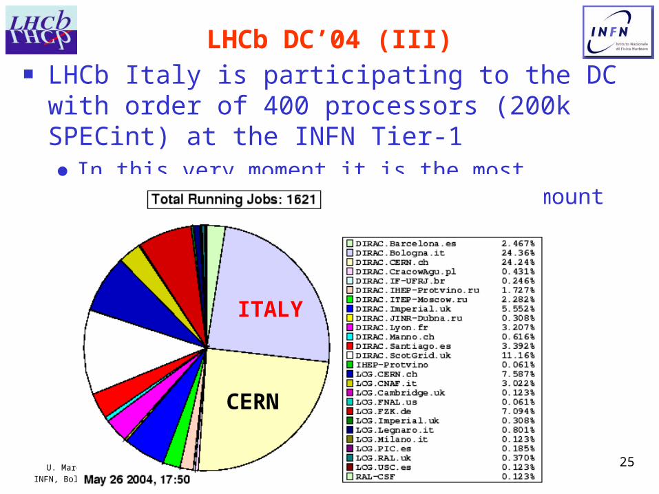
LHCb DC’04 (III)■ LHCb Italy is participating to the DC with order of
400 processors (200k SPECint) at the INFN Tier-1● In this very moment it is the most important regional
centre with an amount of resources comparable to CERN
ITALY
CERN

U. MarconiINFN, Bologna
26
Some ideas for high throughput analysis
WN 1
WN 2
WN m
MGR
I/O nodes
ManagementNode
Clients
Eth
ern
et
swit
ch
ION 1
ION 2
ION n
WN 1
WN 2
WN m
Clients
Eth
ern
et
swit
ch
NAS
A more effective solution:Parallel File System
Classic solution:Network Attached
Storage
bottleneck
U. MarconiINFN, Bologna
27
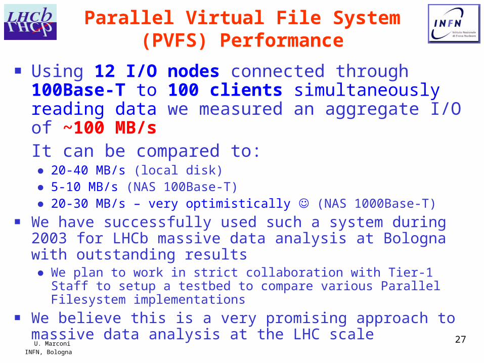
Parallel Virtual File System (PVFS) Performance
■ Using 12 I/O nodes connected through 100Base-T to 100 clients simultaneously reading data we measured an aggregate I/O of ~100 MB/s It can be compared to:● 20-40 MB/s (local disk)● 5-10 MB/s (NAS 100Base-T)● 20-30 MB/s – very optimistically (NAS 1000Base-T)
■ We have successfully used such a system during 2003 for LHCb massive data analysis at Bologna with outstanding results● We plan to work in strict collaboration with Tier-1 Staff to setup a
testbed to compare various Parallel Filesystem implementations■ We believe this is a very promising approach to massive
data analysis at the LHC scale
U. MarconiINFN, Bologna
28
Acknowledgments
We want to thanks the Computig Staff at INFN Bologna for their support in building the L1&HLT event filter farm
We want to express our sincere thanks to the Tier-1 Management and Staff at CNAF for their precious efforts in providing a high quality infrastructure and support, fighting every day with a plenty of technical issues connected to the construction and maintenance of such a large Computing Centre, which is emerging as one of the most important HEP-dedicated European Computing Centres


