62
TDR Framework Technical Design Report CERN/LHCC 2012-007 LHCb TDR 12 25 May 2012 UPGRADE LHCb
| Date post: | 12-Apr-2018 |
| Category: |
Documents |
| Upload: | phungthuan |
| View: | 221 times |
| Download: | 1 times |

CER
N-L
HC
C-2
012-
007
/LH
CB-
TDR
-012
23/0
5/20
12
TDRFramework
Technical Design Report
CERN/LHCC 2012-007
LHCb TDR 12
25 May 2012
UPGRADELHCb


CERN/LHCC 2012-007LHCb TDR 12
25 May 2012
Framework TDR for the LHCb upgrade
The LHCb Collaboration
Abstract
This document is a Framework Technical Design Report for the upgrade of theLHCb experiment. It adds to the information in the Letter of Intent, in particularconcerning the foreseen schedule, cost and participating institutes. Updates aregiven for the physics performance, based on the experience gained with the first fullyear of data taking, on the detector requirements and the progress of the sub-systemR&D. Within the framework presented here, it is expected that the individual sub-system TDRs will follow on completion of the R&D phase in the next year.

ii

The LHCb collaboration
I. Bediaga1, J.M. De Miranda1, F. Ferreira Rodrigues1, J. Magnin1, A. Massafferri1,I. Nasteva1, A.C. dos Reis1
1Centro Brasileiro de Pesquisas Fısicas (CBPF), Rio de Janeiro, Brazil
S. Amato2, K. Carvalho Akiba2, L. De Paula2, O. Francisco2, M. Gandelman2, A. Gomes2,J.H. Lopes2, J.M. Otalora Goicochea2, E. Polycarpo2, M.S. Rangel2, B. Souza De Paula2,D. Vieira2
2Universidade Federal do Rio de Janeiro (UFRJ), Rio de Janeiro, Brazil
C. Gobel3, J. Molina Rodriguez3
3Pontifıcia Universidade Catolica do Rio de Janeiro (PUC-Rio), Rio de Janeiro, Brazil
P. Chen4,39, Y. Gao4, G. Gong4, H. Gong4, F. Jing4, L. Li4, Y. Li4, B. Liu4, H. Lu4, B. Shao4,S. Wu4, T. Xue4, Z. Yang4, X. Yuan4, M. Zeng4, F. Zhang4, Y. Zhang4, L. Zhong4
4Center for High Energy Physics, Tsinghua University, Beijing, China
I. De Bonis5, D. Decamp5, C. Drancourt5, Ph. Ghez5, P. Hopchev5, J.-P. Lees5,I.V. Machikhiliyan5,31, M.-N. Minard5, B. Pietrzyk5, S. T’Jampens5, V. Tisserand5,E. Tournefier5,53, G. Vouters5
5LAPP, Universite de Savoie, CNRS/IN2P3, Annecy-Le-Vieux, France
Z. Ajaltouni6, H. Chanal6, E. Cogneras6, O. Deschamps6, I. El Rifai6, P. Henrard6,M. Hoballah6, M. Jahjah Hussein6, R. Lefevre6, L. Li Gioi6, S. Monteil6, V. Niess6, P. Perret6,D.A. Roa Romero6, K. Sobczak6
6Clermont Universite, Universite Blaise Pascal, CNRS/IN2P3, LPC, Clermont-Ferrand,France
C. Adrover7, E. Aslanides7, J.-P. Cachemiche7, J. Cogan7, P.-Y. Duval7, F. Hachon7,B. Khanji7, R. Le Gac7, O. Leroy7, G. Mancinelli7, E. Maurice7, M. Perrin-Terrin7,F. Rethore7, M. Sapunov7, J. Serrano7, A. Tsaregorodtsev7
7CPPM, Aix-Marseille Universite, CNRS/IN2P3, Marseille, France
S. Barsuk8, C. Beigbeder-Beau8, T. Caceres8, O. Callot8, D. Charlet8, O. Duarte8, J. He8,B. Jean-Marie8, O. Kochebina8, J. Lefrancois8, F. Machefert8, A. Martın Sanchez8, M. Nicol8,P. Robbe8, M.-H. Schune8, M. Teklishyn8, V. Tocut8, B. Viaud8, I. Videau8
8LAL, Universite Paris-Sud, CNRS/IN2P3, Orsay, France
E. Ben-Haim9, M. Benayoun9, P. David9, L. Del Buono9, A. Martens9, F. Polci99LPNHE, Universite Pierre et Marie Curie, Universite Paris Diderot, CNRS/IN2P3, Paris,France
T. Brambach10, Ch. Cauet10, M. Deckenhoff10, M. Domke10, R. Ekelhof10, M. Kaballo10,T.M. Karbach10, F. Kruse10, J. Merkel10, K. Rudloff10, S. Schleich10, M. Schlupp10,B. Spaan10, S. Swientek10, K. Warda10, J. Wishahi10
10Fakultat Physik, Technische Universitat Dortmund, Dortmund, Germany
C. Bauer11, M. Britsch11, C. Fohr11, M. Fontana11, H. Fuchs11, W. Hofmann11, T. Kihm11,
iii

D. Popov11, M. Schmelling11, D. Volyanskyy11, H. Voss11, M. Zavertyaev11,a
11Max-Planck-Institut fur Kernphysik (MPIK), Heidelberg, Germany
S. Bachmann12, A. Bien12, J. Blouw12, F. Dordei12, C. Farber12, E. Gersabeck12,S. Hansmann-Menzemer12, A. Jaeger12, K. Kreplin12, G. Krocker12, C. Linn12, J. Marks12,M. Meissner12, T. Nikodem12, P. Seyfert12, S. Stahl12, J. van Tilburg12, U. Uwer12,S. Wandernoth12, D. Wiedner12, A. Zhelezov12
12Physikalisches Institut, Ruprecht-Karls-Universitat Heidelberg, Heidelberg, Germany
O. Grunberg13, T. Hartmann13, C. Voß13, R. Waldi13
13Institut fur Physik, Universitat Rostock, Rostock, Germany
S. Bifani14, S. Farry14, P. Ilten14, T. Kechadi14, Z. Mathe14, R. McNulty14, R. Wallace14,W.C. Zhang14
14School of Physics, University College Dublin, Dublin, Ireland
D.A. Milanes15, A. Palano15,b
15Sezione INFN di Bari, Bari, Italy
A. Carbone16,c, I. D’Antone16, D. Derkach16,38, A. Falabella16,e, D. Galli16,c, I. Lax16,U. Marconi16, S. Perazzini16,c, V. Vagnoni16, G. Valenti16, M. Zangoli16
16Sezione INFN di Bologna, Bologna, Italy
W. Bonivento17, S. Cadeddu17, A. Cardini17, A. Lai17, G. Manca17,d, R. Oldeman17,d,38,B. Saitta17,d
17Sezione INFN di Cagliari, Cagliari, Italy
W. Baldini18, C. Bozzi18, F. Evangelisti18, L. Landi18,e, A. Mazurov18,33,38, M. Savrie18,e,S. Squerzanti18, S. Vecchi18
18Sezione INFN di Ferrara, Ferrara, Italy
A. Bizzeti19,h, M. Frosini19,f , G. Graziani19, G. Passaleva19, M. Veltri19,g
19Sezione INFN di Firenze, Firenze, Italy
M. Anelli20, F. Archilli20,38, G. Bencivenni20, P. Campana20,38, P. Ciambrone20,P. De Simone20, G. Felici20, G. Lanfranchi20,38, M. Palutan20, A. Saputi20, A. Sarti20,l,B. Sciascia20, F. Soomro20,38
20Laboratori Nazionali dell’INFN di Frascati, Frascati, Italy
R. Cardinale21,i,38, F. Fontanelli21,i, C. Patrignani21,i, A. Petrolini21,i
21Sezione INFN di Genova, Genova, Italy
M. Calvi22,j , S. Furcas22, A. Giachero22, C. Gotti22, M. Kucharczyk22,26,38,j , M. Maino22,C. Matteuzzi22, G. Pessina22
22Sezione INFN di Milano Bicocca, Milano, Italy
G. Carboni23,k, S. De Capua23,k, G. Sabatino23,k, E. Santovetti23,k, A. Satta23
23Sezione INFN di Roma Tor Vergata, Roma, Italy
A.A. Alves Jr24, G. Auriemma24,m, V. Bocci24, G. Martellotti24, G. Penso24,l, D. Pinci24,
iv

R. Santacesaria24, C. Satriano24,m, A. Sciubba24
24Sezione INFN di Roma La Sapienza, Roma, Italy
S. Nisar25
25Institute of Information Technology, COMSATS, Lahore, Pakistan
P. Morawski26, G. Polok26, M. Witek26
26Henryk Niewodniczanski Institute of Nuclear Physics Polish Academy of Sciences, Krakow,Poland
B. Muryn27, A. Oblakowska-Mucha27, K. Senderowska27, T. Szumlak27
27AGH University of Science and Technology, Krakow, Poland
Z. Guzik28, A. Nawrot28, M. Szczekowski28, A. Ukleja28
28Soltan Institute for Nuclear Studies, Warsaw, Poland
I. Burducea29, C. Coca29, M. Dogaru29, A. Grecu29, F. Maciuc29, R. Muresan29,M. Orlandea29, C. Pavel-Nicorescu29, B. Popovici29, S. Stoica29, M. Straticiuc29,E. Teodorescu29
29Horia Hulubei National Institute of Physics and Nuclear Engineering, Bucharest-Magurele,Romania
G. Alkhazov30, B. Bochin30, N. Bondar30, A. Dzyuba30, S. Gets30, V. Golovtsov30,A. Kashchuk30, O. Maev30,38, M. Matveev30, N. Sagidova30, Y. Shcheglov30, S. Volkov30,A. Vorobyev30
30Petersburg Nuclear Physics Institute (PNPI), Gatchina, Russia
V. Balagura31, S. Belogurov31, I. Belyaev31, V. Egorychev31, D. Golubkov31,T. Kvaratskheliya31,38, D. Savrina31, A. Semennikov31, P. Shatalov31, V. Shevchenko31,A. Zhokhov31
31Institute of Theoretical and Experimental Physics (ITEP), Moscow, Russia
A. Berezhnoy32, G. Bogdanova32, I. Komarov32, M. Korolev32, A. Leflat32,38, N. Nikitin32,V. Volkov32, E. Zverev32
32Institute of Nuclear Physics, Moscow State University (SINP MSU), Moscow, Russia
S. Filippov33, E. Gushchin33, O. Karavichev33, L. Kravchuk33, Y. Kudenko33, S. Laptev33,A. Tikhonov33
33Institute for Nuclear Research of the Russian Academy of Sciences (INR RAN), Moscow,Russia
A. Bondar34, S. Eidelman34, P. Krokovny34, V. Kudryavtsev34, L. Shekhtman34, V. Vorobyev34
34Budker Institute of Nuclear Physics (SB RAS) and Novosibirsk State University,Novosibirsk, Russia
A. Artamonov 35, K. Belous35, R. Dzhelyadin35, Yu. Guz35, A. Novoselov35, V. Obraztsov35,A. Ostankov35, V. Romanovsky35, M. Shapkin35, O. Stenyakin35, O. Yushchenko35
35Institute for High Energy Physics (IHEP), Protvino, Russia
v

C. Abellan Beteta36,n, M. Calvo Gomez36,n, A. Camboni36, A. Casajus Ramo36,A. Comerma-Montells36, F. Domingo Bonal36,n, L. Garrido36, D. Gascon36,M. Grabalosa Gandara36, R. Graciani Diaz36, E. Grauges36, E. Lopez Asamar36, J. Mauricio36,V. Mendez-Munoz36,o, A. Perez-Calero Yzquierdo36, E. Picatoste Olloqui36, B. Pie Valls36,C. Potterat36, A. Puig Navarro36, M. Rosello36,n, H. Ruiz36, R. Vazquez Gomez36,X. Vilasis-Cardona36,n
36Universitat de Barcelona, Barcelona, Spain
B. Adeva37, P. Alvarez Cartelle37, X. Cid Vidal37, A. Dosil Suarez37, D. Esperante Pereira37,V. Fernandez Albor37, A. Gallas Torreira37, J.A. Hernando Morata37, A. Pazos Alvarez37,E. Perez Trigo37, M. Plo Casasus37, P. Rodriguez Perez37, J.J. Saborido Silva37,B. Sanmartin Sedes37, C. Santamarina Rios37, M. Seco37, P. Vazquez Regueiro37,J. Visniakov37
37Universidad de Santiago de Compostela, Santiago de Compostela, Spain
J. Albrecht38, F. Alessio38, C. Barschel38, T. Blake38, E. Bonaccorsi38, L. Brarda38,J. Buytaert38, M. Cattaneo38, B. Chadaj38, Ph. Charpentier38, M. Chebbi38, K. Ciba38,M. Clemencic38, J. Closier38, P. Collins38, B. Corajod38, G. Corti38, B. Couturier38,C. D’Ambrosio38, G. Decreuse38, H. Dijkstra38, R. Dumps38, M. Ferro-Luzzi38, R. Forty38,C. Fournier38, M. Frank38, C. Frei38, C. Gaspar38, M. Gersabeck38, V.V. Gligorov38,L.A. Granado Cardoso38, T. Gys38, C. Haen38, E. van Herwijnen38, R. Jacobsson38,O. Jamet38, B. Jost38, M. Karacson38, R. Kristic38, D. Lacarrere38, E. Lanciotti38,C. Langenbruch38, R. Lindner38, G. Liu38, D. Martinez Santos38, R. Matev38, N. Neufeld38,J. Panman38, M. Pepe Altarelli38, D. Piedigrossi38, N. Rauschmayr38, S. Roiser38, L. Roy38,T. Ruf38, H. Schindler38, B. Schmidt38, T. Schneider38, A. Schopper38, R. Schwemmer38,F. Stagni38, V.K. Subbiah38, F. Teubert38, E. Thomas38, D. Tonelli38, M. Ubeda Garcia38,O. Ullaland38, M. Vesterinen38, J. Wicht38, W. Witzeling38, K. Wyllie38, A. Zvyagin38
38European Organization for Nuclear Research (CERN), Geneva, Switzerland
Y. Amhis39, A. Bay39, F. Bernard39, F. Blanc39, J. Bressieux39, G.A. Cowan39,H. Degaudenzi39,38, F. Dupertuis39, V. Fave39, R. Frei39, N. Gauvin39, G. Haefeli39, P. Jaton39,A. Keune39, M. Knecht39, V.N. La Thi39, N. Lopez-March39, J. Luisier39, R. Marki39,B. Muster39, T. Nakada39, A.D. Nguyen39, C. Nguyen-Mau39,p, J. Prisciandaro39,B. Rakotomiaramanana39, J. Rouvinet39, O. Schneider39, P. Szczypka39, S. Tourneur39,M.T. Tran39, G. Veneziano39
39Ecole Polytechnique Federale de Lausanne (EPFL), Lausanne, Switzerland
J. Anderson40, R. Bernet40, A. Buchler-Germann40, A. Bursche40, N. Chiapolini40,M. De Cian40, Ch. Elsasser40, K. Muller40, J. Palacios40, C. Salzmann40, S. Saornil Gamarra40,N. Serra40, O. Steinkamp40, U. Straumann40, M. Tobin40, A. Vollhardt40
40Physik-Institut, Universitat Zurich, Zurich, Switzerland
R. Aaij41, S. Ali41, H. Band41, Th. Bauer41, M. van Beuzekom41, V. van Beveren41,H. Boer Rookhuizen41, L. Ceelie41, V. Coco41, P.N.Y. David41, K. De Bruyn41, P. De Groen41,D. van Eijk41, C. Farinelli41, V. Gromov41, B. van der Heijden41, V. Heijne41,W. Hulsbergen41, E. Jans41, F. Jansen41, L. Jansen41, P. Jansweijer41, R. Kluit41,P. Koppenburg41, A. Kozlinskiy41, J. van Leerdam41, M. Martinelli41, M. Merk41, I. Mous41,
vi

B. Munneke41, S. Oggero41, M. van Overbeek41, A. Pellegrino41, O. van Petten41,E. Roeland41, K. de Roo41, A. Schimmel41, H. Schuijlenburg41, T. Sluijk41, B. Storaci41,P. Tsopelas41, N. Tuning41, W. Vink41, P. Wenerke41, L. Wiggers41, F. Zappon41, A. Zwart41
41Nikhef National Institute for Subatomic Physics, Amsterdam, The Netherlands
J. van den Brand42, F. Dettori42, T. Ketel42, R.F. Koopman42, J. Kos42, R.W. Lambert42,F. Mul42, G. Raven42, M. Schiller42, S. Tolk42
42Nikhef National Institute for Subatomic Physics and VU University Amsterdam, Amsterdam,The Netherlands
A. Dovbnya43, S. Kandybei43, I. Raniuk43, I. Shapoval43,38, O. Shevchenko43
43NSC Kharkiv Institute of Physics and Technology (NSC KIPT), Kharkiv, Ukraine
V. Iakovenko44, Y. Nikolaiko44, O. Okhrimenko44, M. Pugatch44, V. Pugatch44
44Institute for Nuclear Research of the National Academy of Sciences (KINR), Kyiv, Ukraine
P.J.W. Faulkner45, I.R. Kenyon45, C. Lazzeroni45, J. McCarthy45, M.W. Slater45,N.K. Watson45
45University of Birmingham, Birmingham, United Kingdom
M. Adinolfi46, J. Benton46, N.H. Brook46, A. Cook46, M. Coombes46, T. Hampson46,S.T. Harnew46, P. Naik46, J.H. Rademacker46, A. Solomin46, D. Souza46, J.J. Velthuis46,D. Voong46
46H.H. Wills Physics Laboratory, University of Bristol, Bristol, United Kingdom
W. Barter47, M.-O. Bettler47, H.V. Cliff47, J. Garra Tico47, V. Gibson47, S. Gregson47,S.C. Haines47, C.R. Jones47, S. Sigurdsson47, D.R. Ward47, S.A. Wotton47, S. Wright47
47Cavendish Laboratory, University of Cambridge, Cambridge, United Kingdom
J.J. Back48, D. Craik48, D. Dossett48, T. Gershon48,38, M. Kreps48, T. Latham48, T. Pilar48,A. Poluektov48,34, M.M. Reid48, R. Silva Coutinho48, M. Whitehead48, M.P. Williams48,49
48Department of Physics, University of Warwick, Coventry, United Kingdom
S. Easo49, R. Nandakumar49, A. Papanestis49, G.N. Patrick49, S. Ricciardi49, F.F. Wilson49
49STFC Rutherford Appleton Laboratory, Didcot, United Kingdom
S. Benson50, P.E.L. Clarke50, R. Currie50, S. Eisenhardt50, C. Fitzpatrick50, D. Lambert50,H. Luo50, H. Mejia50, F. Muheim50, M. Needham50, S. Playfer50, A. Sparkes50, Y. Xie50
50School of Physics and Astronomy, University of Edinburgh, Edinburgh, United Kingdom
M. Alexander51, J. Beddow51, S. Borghi51,54, L. Eklund51, D. Hynds51, S. Ogilvy51,M. Pappagallo51, E. Rodrigues51,54, P. Sail51, F.J.P. Soler51, P. Spradlin51
51School of Physics and Astronomy, University of Glasgow, Glasgow, United Kingdom
T.J.V. Bowcock52, H. Brown52, G. Casse52, S. Donleavy52, K. Hennessy52, E. Hicks52,T. Huse52, D. Hutchcroft52, M. Liles52, G.D. Patel52, K. Rinnert52, T. Shears52, N.A. Smith52
52Oliver Lodge Laboratory, University of Liverpool, Liverpool, United Kingdom
L. Carson53, G. Ciezarek53, S. Cunliffe53, U. Egede53, A. Golutvin53,31,38, S. Hall53, P. Owen53,
vii

C.J. Parkinson53, M. Patel53, K. Petridis53, A. Richards53, T. Savidge53, I. Sepp53, A. Shires53,D. Websdale53, M. Williams53
53Imperial College London, London, United Kingdom
R.B. Appleby54, R.J. Barlow54, T. Bird54, P.M. Bjørnstad54, D. Brett54, J. Harrison54,G. Lafferty54, G. McGregor54, D. Moran54, C. Parkes54, M. Smith54, A.D. Webber54
54School of Physics and Astronomy, University of Manchester, Manchester, United Kingdom
M. Brock55, M. Charles55, N. Harnew55, J.J. John55, M. John55, S. Malde55,A. Nomerotski55,38, A. Powell55, C. Thomas55, S. Topp-Joergensen55, G. Wilkinson55
55Department of Physics, University of Oxford, Oxford, United Kingdom
B. Meadows56, M.D. Sokoloff56
56University of Cincinnati, Cincinnati, OH, United States
M. Artuso57,38, S. Blusk57, A. Borgia57, T. Britton57, J. Garofoli57, B. Gui57,C. Hadjivasiliou57, R. Mountain57, B.K. Pal57, A. Phan57, W. Qian57, T. Skwarnicki57,S. Stone57,38, J. Wang57, Z. Xing57, L. Zhang57.57Syracuse University, Syracuse, NY, United States
aP.N. Lebedev Physical Institute, Russian Academy of Science (LPI RAS), Moscow, RussiabUniversita di Bari, Bari, ItalycUniversita di Bologna, Bologna, ItalydUniversita di Cagliari, Cagliari, ItalyeUniversita di Ferrara, Ferrara, ItalyfUniversita di Firenze, Firenze, ItalygUniversita di Urbino, Urbino, ItalyhUniversita di Modena e Reggio Emilia, Modena, ItalyiUniversita di Genova, Genova, ItalyjUniversita di Milano Bicocca, Milano, ItalykUniversita di Roma Tor Vergata, Roma, ItalylUniversita di Roma La Sapienza, Roma, ItalymUniversita della Basilicata, Potenza, ItalynLIFAELS, La Salle, Universitat Ramon Llull, Barcelona, SpainoPort d’Informacio Cientıfica (PIC), Barcelona, SpainpHanoi University of Science, Hanoi, Viet Nam
viii

Contents
1 Introduction 11.1 Physics motivation . . . . . . . . . . . . . . . . . . . . . . . . . . . . . . . 11.2 Evolution of requirements and main technical options . . . . . . . . . . . . 61.3 Requirements to the LHC . . . . . . . . . . . . . . . . . . . . . . . . . . . 7
2 Evolution of sub-system R&D since the LoI 92.1 Tracking systems . . . . . . . . . . . . . . . . . . . . . . . . . . . . . . . . 9
2.1.1 Vertex Locator . . . . . . . . . . . . . . . . . . . . . . . . . . . . . 102.1.2 Trigger Tracker . . . . . . . . . . . . . . . . . . . . . . . . . . . . . 122.1.3 Tracker stations . . . . . . . . . . . . . . . . . . . . . . . . . . . . . 132.1.4 Readout front-end ASIC for silicon strip detectors . . . . . . . . . . 192.1.5 Track reconstruction . . . . . . . . . . . . . . . . . . . . . . . . . . 19
2.2 Particle identification . . . . . . . . . . . . . . . . . . . . . . . . . . . . . . 212.2.1 RICH system . . . . . . . . . . . . . . . . . . . . . . . . . . . . . . 212.2.2 Calorimeter system . . . . . . . . . . . . . . . . . . . . . . . . . . . 232.2.3 Muon system . . . . . . . . . . . . . . . . . . . . . . . . . . . . . . 24
2.3 Data processing . . . . . . . . . . . . . . . . . . . . . . . . . . . . . . . . . 252.3.1 Data acquisition and trigger . . . . . . . . . . . . . . . . . . . . . . 252.3.2 Computing . . . . . . . . . . . . . . . . . . . . . . . . . . . . . . . 26
2.4 Safety . . . . . . . . . . . . . . . . . . . . . . . . . . . . . . . . . . . . . . 27
3 Schedule, costs and interest of institutes 283.1 Schedule . . . . . . . . . . . . . . . . . . . . . . . . . . . . . . . . . . . . . 283.2 Cost . . . . . . . . . . . . . . . . . . . . . . . . . . . . . . . . . . . . . . . 403.3 Expressions of interest . . . . . . . . . . . . . . . . . . . . . . . . . . . . . 45
ix

1 Introduction
With the Letter of Intent (LoI) for the LHCb Upgrade [1], submitted in March 2011, theLHCb Collaboration declared its interest in upgrading the detector to 40 MHz readoutwith a very flexible software-based trigger. This will allow the data rate to be increasedsubstantially, as well as the trigger efficiency, leading to improvements in annual signalyields compared to those obtained by LHCb in 2011 by a factor of around ten for muonicB decays and twenty or more for heavy-flavour decays to hadronic final states. In additionto the significant increase in sensitivity for flavour physics, the experiment will be capableof triggering on other interesting signatures, such as long-lived particles, and thus act asa general purpose detector in the forward region.
Following encouragement by the LHCC to proceed to the detector Technical DesignReports (TDRs), it had been decided to first present this Framework TDR that providesinformation in particular about the schedule, cost and participating institutes. Based onthe detailed studies presented in the LoI, this document gives an update on the expectedphysics performance, on the requirements to the detector and on the sub-systems R&D.A detailed discussion is then given of the schedule and cost of the different detectorcomponents, as well as the expression of interests from the collaborating institutes.
Since the sub-systems are in a period of R&D there are still a number of options openconcerning the technologies, that are described here. Following the completion of theR&D phase, the remaining choices of baseline technology will be made in time for thesub-system TDRs, which will follow on a timescale of the next year or so. The overallschedule sees installation of the upgraded experiment in the second long shutdown of theLHC in 2018, to be ready for data taking in 2019.
1.1 Physics motivation
The detailed physics motivation for the LHCb upgrade is described in the Letter of In-tent [1]. The LoI was, however, written when only about 35 pb−1 of data had beenrecorded, accumulated from
√s = 7 TeV pp collisions in 2010. During 2011 both the
LHC machine and the LHCb detector performed superbly, allowing LHCb to accumulate1.0 fb−1 of
√s = 7 TeV pp collisions that is available for physics analysis. Indeed, the re-
sults of many analyses based on some or all of this data set have already been submittedfor publication. The results to date cover topics in the core flavour physics programmeof LHCb in rare decays such as B0
s → µ+µ− [2] and B0 → K∗0µ+µ− [3] and in studies ofCP violation, such as the measurement of the weak phase in B0
s oscillations [4] and thefirst evidence for matter-antimatter asymmetries in both the charm sector [5] and in B0
s
decays [6]. It is therefore worthwhile to update the estimated performance that can beachieved by the upgraded detector in the light of these new results.
In addition, LHCb has continued to seek possibilities to enhance its physics reachby considering new analyses. To this end the collaboration organised two workshops,in Nov. 2011 and Apr. 2012, to discuss with invited theorists both the implications ofits latest results and the prospects for new and improved measurements. These meetings
1

focussed mainly on the flavour physics aspects of the LHCb physics programme: they wereorganised with sessions on rare decays, CP violation in the B sector, and charm mixingand CP violation, with additional dedicated talks on the interplay of flavour physicsand measurements from ATLAS and CMS. Nonetheless, it remains the case that thephysics programme of the upgraded LHCb experiment extends beyond flavour physics.Indeed, the impact of LHCb measurements involving (for example) electroweak gaugebosons [7] has also been widely discussed both at dedicated workshops and in meetingson the implications of LHC results (ATLAS, CMS and LHCb) on TeV scale physics. Afull report is being prepared on the outcome of the LHCb workshops with theorists, andthe updated sensitivity studies for the upgrade [8], also in view of the preparation for theEuropean Strategy for Particle Physics. Here only a brief summary is given.
To be conservative, the sensitivity studies reported in this document all assume de-tector performance as achieved during 2011 data taking. The exception is for the triggerefficiency, where channels selected by hadron, photon or electron hardware triggers are ex-pected to have their efficiencies doubled (channels selected by muon triggers are expectedto have marginal gains, that have not been included in the extrapolations). In reality thegain in trigger efficiency will vary channel by channel, and is expected to be significantlylarger than the nominal factor of 2 for some charm decays, for example. More detailedstudies of these effects, and of the impact of the new detector technologies to be used inthe upgrade, are planned to be performed for the sub-system TDRs.
Several other assumptions are made for the upgrade:
• LHC collisions will be at√s = 14 TeV, with heavy flavour production cross-sections
scaling linearly with√s;
• the instantaneous luminosity in LHCb will be Linst = 1033 cm−2 s−1: this will beachieved with 25 ns separation between bunches and an average number of visibleinteractions per crossing µ = 2;
• the external crossing angle of the beams will be in the vertical plane (as alreadyimplemented for 2012 data taking), providing opposite beam crossing angles of equalamplitude for field-up and field-down polarities;
• LHCb will change the polarity of its dipole magnet with similar frequency as in2011/12 data taking, to equalise approximately the amount of data taken with eachpolarity for better control of potential systematic biases;
• the annual integrated luminosity will be Lint = Linst × tLHC = 1033 cm−2 s−1 × 5 ×106 s = 5 fb−1 (where the expected LHC annual operational time tLHC is consistentwith current experience);
• the upgraded experiment will collect a total sample of 50 fb−1.
The sensitivity to various flavour observables is summarised in Table 1. This is anupdated version of a similar summary that appears as Table 2.1 in the LoI [1]. The
2

Typ
eO
bse
rvab
leC
urr
ent
LH
Cb
Upgra
de
Theo
rypre
cisi
on20
18(5
0fb
−1)
unce
rtai
nty
B0 s
mix
ing
2βs
(B0 s→
J/ψφ
)0.
10[9
]0.
025
0.00
8∼
0.00
32β
s(B
0 s→
J/ψf 0
(980
))0.
17[1
0]0.
045
0.01
4∼
0.01
Afs(B
0 s)
6.4×
10−
3[1
8]0.
6×
10−
30.
2×
10−
30.
03×
10−
3
Glu
onic
2βeff s
(B0 s→
φφ
)–
0.17
0.03
0.02
pen
guin
2βeff s
(B0 s→
K∗0K
∗0)
–0.
130.
02<
0.02
2βeff
(B0→
φK
0 S)
0.17
[18]
0.30
0.05
0.02
Rig
ht-
han
ded
2βeff s
(B0 s→
φγ
)–
0.09
0.02
<0.
01cu
rren
tsτ
eff(B
0 s→
φγ
)/τ B
0 s–
5%
1%
0.2
%E
lect
row
eak
S3(B
0→
K∗0µ
+µ−
;1<q2<
6G
eV2 /c4
)0.
08[1
4]0.
025
0.00
80.
02p
engu
ins 0A
FB(B
0→
K∗0µ
+µ−
)25
%[1
4]6
%2
%7
%A
I(Kµ
+µ−
;1<q2<
6G
eV2 /c4
)0.
25[1
5]0.
080.
025
∼0.
02B
(B+→
π+µ
+µ−
)/B
(B+→
K+µ
+µ−
)25
%[1
6]8
%2.
5%
∼10
%H
iggs
B(B
0 s→
µ+µ−
)1.
5×
10−
9[2
]0.
5×
10−
90.
15×
10−
90.
3×
10−
9
pen
guin
B(B
0→
µ+µ−
)/B
(B0 s→
µ+µ−
)–
∼10
0%
∼35
%∼
5%
Unit
arit
yγ
(B→
D(∗
) K(∗
) )∼
10–1
2[1
9,20
]4
0.9
neg
ligi
ble
tria
ngl
eγ
(B0 s→
DsK
)–
11
2.0
neg
ligi
ble
angl
esβ
(B0→
J/ψ
K0 S)
0.8
[18]
0.6
0.2
neg
ligi
ble
Char
mA
Γ2.
3×
10−
3[1
8]0.
40×
10−
30.
07×
10−
3–
CP
vio
lati
on∆A
CP
2.1×
10−
3[5
]0.
65×
10−
30.
12×
10−
3–
Tab
le1:
Sta
tist
ical
sensi
tivit
ies
ofth
eL
HC
bupgr
ade
toke
yob
serv
able
s.F
orea
chob
serv
able
the
curr
ent
sensi
tivit
yis
com
par
edto
that
whic
hw
ill
be
achie
ved
by
LH
Cb
bef
ore
the
upgr
ade,
and
that
whic
hw
ill
be
achie
ved
wit
h50
fb−
1
by
the
upgr
aded
exp
erim
ent.
Syst
emat
icunce
rtai
nti
esar
eex
pec
ted
tob
enon
-neg
ligi
ble
for
the
mos
tpre
cise
lym
easu
red
quan
titi
es.
3
measurements considered include CP -violating observables, rare decays and fundamentalparameters of the CKM Unitarity Triangle. The current precision, either from LHCbmeasurements or averaging groups [18, 19, 20] is given and compared to the estimatedsensitivity with the upgrade. As an intermediate step, the estimated precision that can beachieved prior to the upgrade is also given for each observable. For this, a total integratedluminosity of 1.0 (1.5, 4.0) fb−1 at pp centre-of-mass collision energy
√s = 7 (8, 13) TeV
recorded in 2011 (2012, 2015–17) is assumed. Another assumption is that the currentefficiency of the muon hardware trigger can be maintained at higher
√s, but that higher
thresholds will be necessary for other triggers, reducing the efficiency for the relevantchannels by a factor of 2 at
√s = 13 TeV.
The extrapolations assume the central values of the current measurements, or theStandard Model where no measurement is available. While the sensitivities given includestatistical uncertainties only, preliminary studies of systematic effects suggest that thesewill not affect the conclusions significantly, except in the most precise measurements,such as those of Afs(B
0s ), AΓ and ∆ACP . Branching fraction measurements of B0
s mesonsrequire knowledge of the ratio of fragmentation fractions fs/fd for normalisation [21].The uncertainty on this quantity is limited by knowledge of the branching fraction ofD+
s → K+K−π+, and improved measurements of this quantity will be necessary to avoida limiting uncertainty on, for example, B(B0
s → µ+µ−). The determination of 2βs fromB0
s → J/ψ φ provides an example of how systematic uncertainties can be controlled formeasurements at the LHCb upgrade. In the most recent measurement [9], the largestsource of systematic uncertainty arises due to the constraint of no direct CP violation thatis imposed in the fit. With larger statistics, this constraint can be removed, eliminatingthis source of uncertainty. Other sources, such as the background description and angularacceptance, are already at the 0.01 rad level, and can be reduced with more detailedstudies.
In the Standard Model (SM), the parameters of CP violation in B0s mixing are highly
constrained to be close to zero by global fits to the CKM matrix. LHCb has measured themixing phase 2βs = −φs in both J/ψ φ and J/ψ f0(980) final states, with results that areconsistent with the SM within the uncertainties [9, 10]. However, tensions in the globalCKM fits (see, for example, Ref. [11]) suggest that deviations may be present at the levelof a few degrees (∼ 0.04 rad, in the units of Table 1), motivating much more precisemeasurements. A complementary measurement, Afs, can be made using semileptonicdecays. This analysis requires excellent control of systematic uncertainties to be sensitiveto small deviations from the SM prediction of O(10−4).
Decays dominated by b→ s loop (penguin) transitions provide additional sensitivity tocontributions beyond the SM. The B0
s decays to φφ and K∗0K∗0 final states, both alreadyobserved at LHCb [12, 13], are particularly interesting since these effects could appearin both time-dependent and angular distributions. Another important measurement isthat of the time-dependent decay distribution in B0
s → φγ decays. Determination of theeffective CP -violation and lifetime parameters provides the most promising way to studythe polarisation of the emitted photon, and is therefore uniquely sensitive to models thatpredict new right-handed currents.
4

Rare decays involving dimuon pairs constitute a significant part of the flavour physicsprogramme of the LHCb experiment, and this will remain the case in the upgrade. Asstatistics increase, a larger set of angular observables in B0 → K∗0µ+µ− decays can bemeasured. The first measurement of the zero-crossing point (s0) of the forward-backwardasymmetry in this decay has recently been presented by LHCb [14], demonstrating thepotential for the upgrade to fully explore the phase space for contributions beyond theSM. Another important observable with low theoretical uncertainty is the transverse po-larisation asymmetry, which is probed by the parameter S3.
LHCb has also recently published the world’s most precise measurements of isospinasymmetries in b → sµ+µ− decays [15]. These have generated significant interest in thetheory community, and this sector will be further explored as more data are accumu-lated. Similarly, the first observation of B+ → π+µ+µ− [16] shows the potential for ameasurement of |Vtd/Vts| in loop-mediated transitions. Note that some values quoted inTable 1 are integrated over the dimuon invariant mass range 1 < q2 < 6 GeV2/c4 to givea representative estimate of the sensitivity – however the full differential distribution willbe studied.
The rare decay B0s → µ+µ− is a golden channel to search for effects beyond the Stan-
dard Model. Although the latest measurement from LHCb [2] rules out new contributionsof comparable size to that from the SM, much more precise measurements are well moti-vated since the theoretical prediction for the branching fraction has low uncertainty andthe true value may be smaller than the SM expectation. With the 50 fb−1 data set itwill also be possible to measure the rate of the B0 decay to two muons down to the SMprediction: the ratio of B0 to B0
s branching fractions is given by |Vtd/Vts|2 in the SM andany extension with minimal flavour violation, making this a crucial channel to diagnosethe origin of any non-SM contributions.
The measurement of the angle γ of the Unitarity Triangle from B → DK decays is aSM benchmark. The first results from LHCb [17] already make a significant impact on theglobal averages – however, measurements at the degree-level of sensitivity are necessaryto match the precision in lattice QCD. Similarly, improved measurements of the angle βwill further constrain the global fits, and may reveal contributions beyond the SM if the“tensions” that are present in the current data persist.
In the charm sector, the evidence for CP violation from LHCb [5] has prompted a greatdeal of theoretical interest, which has highlighted several other observables that shouldbe measured. Although hadronic uncertainties cloud the interpretation of the currentmeasurement, when additional observables are measured it will be possible to constrainthese effects, and hence to determine if the origin of the asymmetry is from physics beyondthe SM. It is particularly important to be able to distinguish CP -violation effects fromcharm mixing and those from decay.
Although other experiments will study flavour-physics observables in a similar time-frame to the LHCb upgrade, the sample sizes in most exclusive B and D final states willbe far larger than those that will be collected elsewhere, for example at the upgradede+e− B factories. The LHCb upgrade will have no serious competition in its study of B0
s
decays and CP violation. Similarly the yields in charmed-particle decays to final states
5

consisting of only charged tracks cannot be matched by any other experiment.It must be emphasised that in addition to the physics summarised in Table 1, the up-
graded experiment will have exciting opportunities to perform studies that will shed lighton the lepton sector, and in topics beyond flavour physics. LHCb will be best-placed ofall the LHC experiments to make an improved determination of the effective electroweakmixing angle, and to combat the systematic uncertainties from parton distribution func-tions that may limit the ATLAS and CMS efforts to measure the mass of the W boson.LHCb will have high sensitivity in the search for new particles with long lifetimes, and willbe able to make QCD studies which are complementary to those possible in the centralregion. First results on some of these topics have recently been reported [22, 23], and willhelp to develop further the physics studies for the sub-system TDRs.
1.2 Evolution of requirements and main technical options
Since submission of the Letter of Intent there has been some evolution of requirementsto the upgraded detector and of the main technical options. In the LoI we consideredoperating the upgraded detector at a luminosity of L = 1 × 1033cm−2s−1 with a fullyflexible software trigger running at a readout rate of 40 MHz. This increases the annualsignal yields by a factor of around ten for muonic B decays and twenty or more forheavy-flavour decays to hadronic final states, as compared to those obtained by LHCb in2011.
For reasons of flexibility, and to allow for possible evolutions of the trigger, we havedecided to design those detectors that need replacement for the 40 MHz upgrade such thatthey can sustain a luminosity of L = 2×1033cm−2s−1. For the other detector componentswe are evaluating the effect of such a luminosity increase. As already discussed in the LoI,operating the detector at L = 2×1033cm−2s−1 has in particular consequences for the areato be covered by the Inner Tracker in order to keep the occupancy in the Outer Trackerat a reasonable level. To account for this we are investigating two main tracker options,a large area silicon-strip Inner Tracker complemented by Outer Tracker straw tubes, ora Central Tracker made from scintillating fibres. The Central Tracker is an evolutionof the scintillating-fibre Inner Tracker described in the LoI, extending the active area ofscintillating fibres to the detector periphery. In parallel to the technical R&D we are alsostudying optimization of the overall tracker layout. This includes re-optimization of theposition of the individual tracking stations as well as their acceptance coverage.
The other sub-detector for which alternative technology options exist is the VertexLocator, where the choice is between strip and pixel sensors. For both options we areinvestigating whether the impact parameter resolution can be improved by moving thesensors closer to the beam as compared to the current detector.
In the following we describe the main evolution in R&D of the different technologiesthat are under consideration for the Tracker System, for the Particle Identification detec-tors, and for Data Processing. The Tracker sub-systems are the Vertex Locator (VELO)made from silicon strips or pixels, the Trigger Tracker (TT) and Inner Tracker (IT) madefrom silicon strips, the Central Tracker (CT) made from scintillating fibres, and the Outer
6
Tracker (OT) made from straw tubes. The Particle Identification detectors are the RingImaging Cerenkov (RICH) detectors, the electromagnetic (ECAL) and hadronic (HCAL)calorimeters, as well as the Muon system. The data processing is sub-divided into Trigger,Data Acquisition (DAQ) and Computing.
In the last chapter the individual sub-system schedules are presented, indicating themajor milestones, together with a first cost estimate and the list of participating insti-tutes.
1.3 Requirements to the LHC
Although the intended instantaneous luminosity for the upgrade of LHCb of up to L =2 × 1033cm−2s−1 is far below the LHC design luminosity, the envisaged instantaneousluminosity has implications for the operation of the LHC. This has been presented anddiscussed at the Chamonix 2012 workshop [24].
A bunch spacing of 25 ns is essential for the LHCb upgrade, to limit the pile-up ofpp interactions at the increased luminosity. In order to maintain a luminosity of L =2 × 1033cm−2s−1 at LHCb throughout a fill of typically 8 hours length by luminosityleveling, the virtual luminosity at the beginning of the fill has to be about four times larger.The resulting value is close to the LHC design luminosity of L = 1 × 1034cm−2s−1. Inorder to protect the triplet quadrupole magnets and other machine elements from particlesleaving the interaction point (IP) at such luminosities, the high luminosity insertions atIP1 and IP5 are equipped with a Target Absorber for Secondaries (TAS) and Neutralparticles (TAN). The question whether a TAS and/or a TAN would also be needed atIP8 is currently addressed in discussions with the machine groups and detailed FLUKAsimulations are planned.
Furthermore, in order to maintain a luminosity of L = 2 × 1033cm−2s−1 at LHCbthroughout a fill, beams would have to be focused in IP8 to a β∗ of about 3.5 m. Theoption of an Achromatic-Telescopic Squeezing (ATS) scheme to get to β∗ values as lowas 0.1 m at the high luminosity IPs has a strong impact on the optics and the matchingsection of the neighboring LHC sectors, hence also on IP8. Studies are ongoing to developpossible ATS optics compatible with the LHCb upgrade requirement and first results arevery encouraging [25].
Issues in relation to the expected radiation levels due to the higher luminosity areaddressed as well. The relocation of some electronics equipment of the machine suchas PLCs (programmable logic controllers) is foreseen already in the first long shutdown(LS1). More simulations are ongoing to determine whether other equipment needs to bemitigated for the proposed upgrade scenario.
Finally, as mentioned in Sec. 1.1, in order to control well the systematic uncertainties inthe measurement of CP asymmetries with LHCb, it is of particular importance that equalamounts of data are taken with the two spectrometer polarities, and that the polarity ofthe LHCb dipole magnet is changed with a frequency similar to 2011/2012. For 25 nsbunch spacing, as required for the upgrade, this is only possible if the external crossingangle is in the vertical plane. As a consequence the effective crossing angle for both
7

magnet polarities will have the same absolute value and will be in a tilted plane. Theimplementation of the external vertical crossing has already been done successfully for theLHC physics run in 2012. However, due to the orientation of the beam screen in the innertriplet, an external vertical crossing angle already at injection has very little aperture andthe change of the crossing plane is only done at the end of squeeze. In order to simplifythis for the long-term future it is important that the beam screen in the inner triplet isrotated.
All these issues are addressed in discussion with the machine groups and by the recentlyformed HL-LHC Coordination group.
8

2 Evolution of sub-system R&D since the LoI
2.1 Tracking systems
In the LoI the role of the tracking detectors in LHCb and their performance in the currentexperiment were presented. The main challenges for the LHCb upgrade were describedand a number of exploration paths have been outlined. Since the LoI, a few points havebeen reconsidered. The main changes are the following:
• The current LHCb Tracker stations are composed of an OT with straw tube detec-tors and an IT with silicon strip detectors to cover the high-occupancy area near thebeam pipe. A new technology for the IT upgrade, based on scintillating fibres, wasintroduced in the LoI, with clear fibres carrying the signal photons from the innerregion to the detectors situated outside the LHCb acceptance. In the mean time,a new scintillating-fibre layout has been proposed, with 2.5 m long fibres coveringthe whole central region of the Tracker stations, from the LHC beam plane all theway to the top and bottom of the LHCb acceptance. In this CT option, the ITand several OT modules are replaced by the new scintillating-fibre modules. Thealternative solution, the IT option, is being explored in parallel and proposes tocover with silicon microstrip sensors an area larger than that covered by the currentIT detector. The two options (CT and IT) are illustrated in Fig. 1.
• The decision has been taken that any change to the LHCb detector should be madesuch that the new implementation is compatible with operation at a leveled, i.e.constant, luminosity of 2 × 1033 cm−2s−1. The consequences for each Tracker sub-detector are briefly discussed below.
• Investigations about a possible reduction of the inner foil radius of the VELO havebeen launched. The impact of such a change are outlined below in the VELOsubsection.
A summary of the detector upgrade layout options for the VELO and Trackers is givenin Table 2.
Subsystem Technology options
VELOmicrostrip silicon sensorspixel sensors
TT microstrip silicon sensors
Tracker stationsOT straw tubes + CT scintillating fibresOT straw tubes (new short modules) + large area silicon IT
Table 2: Summary of detector layout options for the VELO and tracker upgrades.
In the following, the various design options of the tracking detectors and the simula-tion/reconstruction strategy to reach an optimal design choice are briefly reviewed withan emphasis on the evolution since the LoI.
9
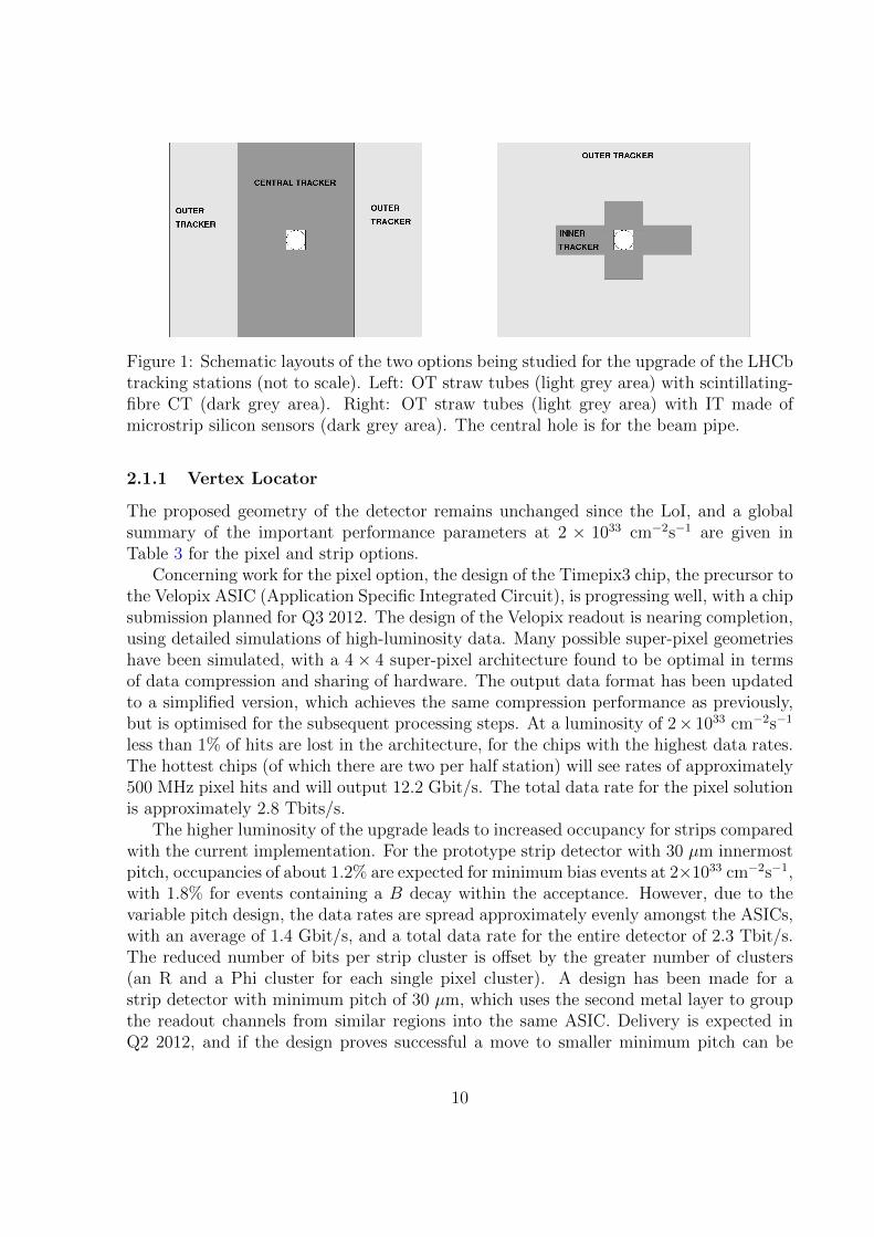
Figure 1: Schematic layouts of the two options being studied for the upgrade of the LHCbtracking stations (not to scale). Left: OT straw tubes (light grey area) with scintillating-fibre CT (dark grey area). Right: OT straw tubes (light grey area) with IT made ofmicrostrip silicon sensors (dark grey area). The central hole is for the beam pipe.
2.1.1 Vertex Locator
The proposed geometry of the detector remains unchanged since the LoI, and a globalsummary of the important performance parameters at 2 × 1033 cm−2s−1 are given inTable 3 for the pixel and strip options.
Concerning work for the pixel option, the design of the Timepix3 chip, the precursor tothe Velopix ASIC (Application Specific Integrated Circuit), is progressing well, with a chipsubmission planned for Q3 2012. The design of the Velopix readout is nearing completion,using detailed simulations of high-luminosity data. Many possible super-pixel geometrieshave been simulated, with a 4 × 4 super-pixel architecture found to be optimal in termsof data compression and sharing of hardware. The output data format has been updatedto a simplified version, which achieves the same compression performance as previously,but is optimised for the subsequent processing steps. At a luminosity of 2× 1033 cm−2s−1
less than 1% of hits are lost in the architecture, for the chips with the highest data rates.The hottest chips (of which there are two per half station) will see rates of approximately500 MHz pixel hits and will output 12.2 Gbit/s. The total data rate for the pixel solutionis approximately 2.8 Tbits/s.
The higher luminosity of the upgrade leads to increased occupancy for strips comparedwith the current implementation. For the prototype strip detector with 30 µm innermostpitch, occupancies of about 1.2% are expected for minimum bias events at 2×1033 cm−2s−1,with 1.8% for events containing a B decay within the acceptance. However, due to thevariable pitch design, the data rates are spread approximately evenly amongst the ASICs,with an average of 1.4 Gbit/s, and a total data rate for the entire detector of 2.3 Tbit/s.The reduced number of bits per strip cluster is offset by the greater number of clusters(an R and a Phi cluster for each single pixel cluster). A design has been made for astrip detector with minimum pitch of 30 µm, which uses the second metal layer to groupthe readout channels from similar regions into the same ASIC. Delivery is expected inQ2 2012, and if the design proves successful a move to smaller minimum pitch can be
10

considered. A pitch of 25 µm should be readily achievable, however the challenge will beto map the larger number of readout channels to the ASICs.
Strips, 128 (256) channel ASIC Pixels# ASICs / half station 40 (20) 12# half stations 42 52# ASICs total 1680 (840) 624# sensors total 84 104Silicon sensor area (m2) 0.187 0.087# channels total 215k 41MCluster size 1.6 (1.6) 2.2# clusters / half station / 25 ns 52.6 (52.6) 25.8# pixel (strip) hit / half station / 25 ns 84.2 (84.2) 56.8# bits / cluster 42.4 (34.4) 52.3# bits / pixel (strip) hit 26.5 (21.5) 23.8Hottest chip output rate 1.4 Gbit/s (2.2) 12.2 Gbit/sCoolest chip output rate 1.4 Gbit/s (2.2) 1.5 Gbit/sData rate / half station 56 Gbit/s (45) 54.3 Gbit/sTotal data rate 2352 Gbit/s (1880) 2823 Gbit/s
Table 3: Summary of VELO design parameters.
Based on experience with the current LHCb detector and LHC beams, it appearsthat several parameters which originally limited the minimum distance of approach of theRF foil material can be reconsidered. The beam positions are stable during physics datataking, the VELO positioning is precise and reliable, and the detector halves are accuratelyadjusted around the luminous region at each and every fill. Preliminary considerationsindicate that the current inner foil radius of 5.5 mm could be reduced to less than 4 mm,perhaps as low as 3 mm. This, potentially, would allow the inner radius of the sensitivearea of the silicon sensor to be reduced from the current 8.2 mm to 7 mm, perhaps even6 mm, which would have a major impact on the LHCb physics performance, owing tothe improved impact parameter resolution. Effort is underway to assess all consequencesand benefits of such a radius reduction. Limitations from the beam size, beam excursionsand foil manufacturing tolerances, effects of the beam image currents in the RF foil, arenow being studied and will be discussed with LHC machine experts to define a new limitfor the inner foil radius. Restrictions arising from the larger fluence and data rates inthe inner detector area, and of the achievable silicon segmentation, are currently beinginvestigated. A decision on the inner foil radius must be taken soon, by Q4 2012, as ithas consequences for several aspects of the VELO detector design.
Work has progressed on the RF foil, which is very complex to manufacture. It is acritical item for the performance of the upgraded detector, as it dominates the material upto the second measured point. A new manufacturing technique is under development thatis particularly important for the L-shaped foil for the pixel option, but also of advantage
11

for the strip option. The shape is milled out of the inside of a solid aluminium alloy block,which is then filled, and the opposite side is then milled to the desired thickness. The firstround of prototyping has proven to be very successful, with a double demonstrator boxwith thickness close to target and leak rates better than 10−6 mbar`/s being produced.A new large plan 5-axis CNC milling machine has been purchased and first tests arecurrently underway. Work has also progressed on the simulation front, in order to bestoptimize the exact shape and depth of the corrugations (see Sec. 2.1.5 below). This workis showing promising first results, and will be used together with the flexibility of themilling approach in terms of minimum radii and foil shapes to optimize the design.
The module construction and the readout chain have seen significant progress. Theflex cable links carrying the analogue signals to the vacuum tank feedthroughs have beenprototyped and constructed in Dupont Pyralux AP-plus, a new material specifically de-veloped for high speed applications which exhibits electrical characteristics necessary forthe upgrade application, and in addition is straightforward to manufacture, with tech-niques similar to the treatment of kapton. Testbench systems with FPGA developmentboards have been set up and initial results are very encouraging, showing that the lengthand flexibility needed for the mechanical performance in the moving VELO halves canbe achieved. Three main techniques are under active investigation for the cooling of themodule itself. The first is a demountable solution with invar tubes mounted in a TPG-CFsandwich cooling block, in conjunction with a through-hole copper plated TPG substrate.An alternative approach is silicon microchannel cooling, whereby the cooling fluid runsbelow the ASICs, removing heat very efficiently and giving an ideal match in terms ofthermal expansion coefficients, removing the need for the diamond substrate. Work isunderway to produce prototypes to check the suitability of this method for the pressureand manifold designs suitable for CO2 cooling, and first demonstrators are expected byQ3 2012. Planar pixel sensors have been produced by two manufacturers, and negotia-tions are continuing with further producers. These will be tested for performance andradiation hardness in 2012.
2.1.2 Trigger Tracker
The overall design concept has not changed since the LoI. The baseline option remains a4-plane solution, with finer y segmentation and full coverage in the detector acceptance. Adetailed model of this detector concept has been developed and will be introduced in thedetector simulation framework soon. Variations of this design including finer segmentationin the direction perpendicular to the LHCb dipole field direction, and additional planesfor more robust tracking, will be studied as well. The performance studies based onMonte-Carlo simulation with different designs are discussed further in Sec. 2.1.5.
The sensors in the innermost region are expected to be exposed to radiation levels ofthe order of 1× 10¹⁴ neq cm−2. At this fluence the RD50 collaboration has demonstratedthat 300 µm thick n-in-p sensors achieve essentially full charge collection at 500 V [26].On the other hand, the fluence is decreasing rapidly with the distance from the beam axis,and at a radius of about 20 cm from the beam axis p-in-n devices are perfectly adequate.
12
Thus, a combination of the two sensor technologies can be envisaged. At a luminosityof 2 × 1033 cm−2s−1, the track density in the sensors located near the beam pipe will besuch that a strip length of a few cm should be considered. The current conceptual designproposes to use 9.8× 9.8 cm2 sensors segmented into 1, 2 or 4 sectors (depending on thelocation of the sensor) of 512 strips each and with a pitch of 183 µm (as in the currentTT detector). Thus, those closest to the beam axis have four rows of 2.5 cm long strips,each with 4 front-end (FE) ASICs (16 per 4-sector sensor). The 2-sector sensors havetwo rows of 5 cm long strips (i.e. 8 ASICs per sensor). The 1-sector sensors are similarto the current TT sensors. It is being considered to mount the FE hybrids directly onthe sensors, a concept inspired by the design for the silicon strip staves of the ATLASupgrade tracker. Compared to the current TT design, this concept introduces the FEhybrid material in the region of highest track density and requires the implementation ofan adequate cooling mechanism to remove the heat from the densely packed FE ASICs.However, this is balanced with the advantage of a much reduced input capacitance, hence alower input noise, which may facilitate usage of significantly thinner sensors. The currentTT sensors are 500 µm thick, while a thickness of 300 µm or less is being consideredfor the TT upgrade. Thinner sensors imply less material in the acceptance and reducedpower dissipation from the product of leakage current and depletion voltage.
An important challenge in this system is the mechanical design, which includes thecooling strategy. A design is being studied which is based on a low-mass active cooling con-cept similar to the one developed for the CMS and ATLAS silicon tracker upgrades [27, 28]and already described in the LoI. A mock-up TT stave is being constructed in order tostudy and optimize the stave design. From these tests and from model calculations, theaffordable sensor thickness and the cooling strategy will be defined, taking into accountexpected signal-over-noise ratio, needed spatial resolution, required temperature at max-imum fluence and material distribution.
Specifications for the FE electronics consistent with the proposed sensor design havebeen developed and are used in the FE electronics design discussed in Sec. ??. The mainfeatures that are important to the TT design are power minimization, as it is plannedto mount the thinned electronics near the sensors to avoid cross talk problems related tolong cables, and fast return to the baseline to avoid spillover hits. If these conditions aresatisfied, binary readout is sufficient in data-acquisition mode, since charge interpolationbetween strips is not expected to bring much improvement for the strip pitch value underconsideration.
2.1.3 Tracker stations
As already described in the LoI, current experience with the LHCb detector and prelim-inary Monte-Carlo simulation results show that the occupancy in the inner area (nearthe beam pipe) will become too large for the most central OT straw tube modules at theLHCb upgrade luminosity. A new design of the detectors in the central area is needed,along with a new definition of the inner (or central) and outer regions.
In the LoI, several exploratory solutions were exposed, such as replacement of the
13

silicon IT by thin scintillating fibres, replacement of the central OT straw modules bythick scintillating fibres, and replacement of the current silicon IT by a larger area siliconIT (with shorter OT straw modules).
Two solutions are currently being studied in parallel. A conceptual design of a large-area IT has been produced, while the scintillating-fibre design effort is now concentratingon a design in which thin-fibre modules replace the central OT modules and the IT.
Both solutions foresee the presence of straw-tube modules to cover the remaining detec-tion area (with the IT solution requiring the additional production of shorter straw-tubemodules). All straw-tube modules will be equipped with new FE and readout electronicscompatible with 40 MHz data acquisition, as described in detail in the LoI.
The issue of radiation resistance of both the fibres and SiPM for their readout wasalready mentioned in the LoI and is being extensively studied. Important questionsregarding the viability of this technology will be addressed this year (2012), so thatthe effort can be focussed on the optimization of the Tracker stations with a limitedcombination of detector technologies.
Silicon strip Inner Tracker
As presented in the LoI, the present IT detector has hardly any deterioration in trackingefficiency at 2× 1033 cm−2s−1 compared to the (current LHCb) nominal luminosity [1]. Anew silicon strip IT, if sufficiently large, would give a sound solution in combination withshorter OT modules in the central region.
A substantial fraction of the hits in the OT originate from secondary particles gener-ated in the beam-pipe support and IT detector, mainly from photon conversions. Hence,if redesigned, two considerations are of primary importance: (a) increase the transversesize of the IT detector to push out the inner limit of the OT edge and (b) improve theIT detector transparency to reduce further the OT occupancy in the innermost region.The choice of the minimum hole size is currently being investigated with a detailed LHCbupgrade simulation, which includes as one of the options a lighter silicon IT detectordescription (see Sec. 2.1.5).
The current LHCb IT detector has a “swiss cross”-like geometry with transverse di-mensions width×height ≈ 126×22 (41) cm2 (the number in brackets designates the detec-tor height in the central part, across the beam pipe). A maximum OT occupancy of 25% inthe hottest straw could be achieved with an IT detector of dimensions ≈ 255×42 (63) cm2,which would have approximately four times as many silicon sensors as in the present IT.The track fraction covered by the IT would increase from 33% to 54%.
Preliminary results on detector occupancy were obtained with the LHCb Monte-Carlosimulation package described in Chapter 11 of the LoI [1], in the so-called “minimalupgrade” configuration (lighter beam pipe support, IT/OT z positions swapped). Figure 2shows the expected occupancy at L = 2 × 1033 cm−2s−1 for inclusive B events at
√s =
14 TeV. Three cases are compared:
(a) with the current LHCb IT detector (≈ 126× 22 (41) cm2);
(b) with a larger IT coverage (2-sensor ladders, ≈ 255× 42 (63) cm2);
14

Figure 2: OT occupancy as a function of x for three different IT configurations in the“minimal upgrade” LHCb simulation (see text).
(c) with an even larger IT coverage (3-sensor ladders, ≈ 255× 63 (84) cm2).
Note that, in all three cases, the IT/OT material description was that of the current LHCbdetector (no benefit from a lighter IT design). The OT hits falling inside the redefinedinner hole were simply not counted as OT hits. The main conclusions are that an OToccupancy of 25% or less seems within reach with 2-sensor ladders (and a mass-optimizeddetector), while an OT occupancy of less than 20% could be achieved straightforwardlywith 3-sensor ladders. What occupancy is acceptable in the hottest OT region will soonbe determined with the LHCb upgrade simulation.
Three concepts are being studied to minimize the amount of material with respect tothe current LHCb design:
1. Convective cooling: use of convective heat transfer for cooling, instead of bulk con-duction, will drastically reduce the amount of material in the acceptance. Radiationaging simulations show that a silicon temperature between 0 and 10 C will be suffi-
15
cient for an upgrade silicon IT. The conceptual design thermally isolates the siliconladders from the FE electronics, which are the dominant heat source. The use ofthin flex cables inspired by the ALICE design [29] is being studied. With a 10 cmflex cable a signal-over-noise ratio of more than 10 can easily be achieved. Thisapproach would also push out the FE hybrid to regions of lower particle flux. Pre-liminary estimations show that cold gas circulation is largely sufficient to maintainthe silicon at the desired temperature while efficiently evacuating the heat from theFE electronics. Thermal simulation studies are underway and an air-cooled mock-up is being manufactured in order to demonstrate the feasibility of this conceptualdesign and to explore its operational aspects.
2. Self-supporting ladders: the rigidity of the silicon sensors will be exploited to min-imize additional supporting material, and silicon sensors will be made to overlapwithin a ladder. Sensor-to-sensor bump bonding is being investigated, though con-ventional wire bonding can also be applied.
3. Minimization of the number of IT layers: currently, 12 layers are used, while per-formance measures indicate that 10 layers may be sufficient. This is being studiedwith the detailed simulation described in Sec. 2.1.5.
Scintillating-fibre Central Tracker
Tracking downstream of the dipole magnet with scintillating-fibre modules in the centralregion is being considered. In this new configuration, the existing outermost straw tubemodules, four on each side, are kept as in the current LHCb detector and their electronicsupgraded to allow readout at 40 MHz. The central part (OT and IT) is replaced withscintillating fibre modules covering the full height of the detector. The upper and lowerhalves of the modules contain 2.5 m long scintillating fibres, separated with mirrors at theinner boundary and read out with Silicon Photomultipliers (SiPM) mounted outside theLHCb acceptance. With this configuration, passive material in the detector acceptanceis minimized and exposure to radiation is reduced for the SiPMs and FE electronics.
One of the key R&D challenges will be to determine how the SiPM performance willevolve as a function of radiation dose and under what conditions these photon detectorswill represent a viable solution for the LHCb CT. The radiation fluence at the SiPMlocation is expected to be of the order of 1012 neq cm−2. Besides previously describedirradiation studies with 65 MeV protons and with neutrons from a PuBe source [1], SiPMsamples have been placed in the LHCb detector at the bottom of the tracking stationsduring the 2011 data taking period. Figure 3 shows the result of this SiPM irradiationstudy. The red triangles show, as a function of time, the leakage current of a sample SiPMthat was mounted in 2011 at the position of the OT readout boxes and not shielded. Theblue squares show the same for a sample SiPM in a similar location, but shielded with100 mm of polyethylene containing 5% boron. This SiPM sample shows an increase indark current that is approximately a factor two lower than for unprotected sensors at thesame location. Adding 1 mm of Pb shielding (and then 1 mm of Cd) between the SiPM
16

Figure 3: Result of an irradiation study of SiPM. The red triangles show, as a function oftime, the leakage current of a sample SiPM that was mounted at the position of the OTreadout boxes and not shielded. The continuous vertical line indicates the date when theSiPM was replaced with another one of different pixel size. The blue squares show theleakage current of a sample SiPM in a similar location, but shielded with polyethylene.The dot-dashed (dashed) vertical line indicates the date when the shielding was increasedby adding 1 mm of Pb (1 mm of Cd) between the SiPM and the polyethylene. The greencrosses show the integrated luminosity at IP8 in 2011 (scale on the right axis).
and the polyethylene had little impact on the evolution of the leakage current. The effectsof radiation damage can also be reduced by operating the SiPMs at low temperature. Thedark current is predicted to be reduced by a factor 2 for about every 8 C temperature step.The option to cool the SiPM is being studied, with a temperature as low as −25 C beingconsidered. This R&D effort will determine whether a combination of neutron shieldingand active cooling will allow the SiPM lifetime to be extended to the required level. Thesignal deterioration due to radiation damage in the fibres was already mentioned in theLoI and will now be measured on irradiated 2.5 m modules.
Figure 4: Cross section photograph of a recently built 2.5 m long scintillating-fibre module.
The techniques for the production of fibre matrices are still under development for
17

both methods presented in the LoI, namely winding fibres on a cylindrical surface ofradius larger than 40 cm or on a long cuboid. Dummy fibre matrices have been producedwith both methods. Recently, a 2.5 m long sample module has been fabricated on thecylindrical barrel with scintillating fibres of 0.25 mm diameter. The sample contained fivelayers of about 100 fibres each. Figure 4 shows a photograph of the cross section of this2.5 m long module. The distance between the centres of adjacent fibres was measured.Figure 5 shows that the fibres are positioned with an accuracy of 6 µm (RMS) relativeto each other. Such prototype modules will be characterized with SiPM readout and testbeam particles in 2012.
Figure 5: Distribution of the measured distance (in µm) between the centres of adjacentfibres for the sample module shown in Fig. 4.
A dedicated FE electronics chip is being designed for the readout of the SiPMs. Thespecifications for the signal processing are very dependent on the detector technology andgeometry. First studies show that a 5-bit digitization is appropriate while preserving theneeded detector resolution. However, specifications for the digital signal processing unitare still evolving, and are dependent on the final detector geometry choices.
As discussed in Sec. 2.1.5, detailed simulation studies will provide information aboutthe optimal geometry of the detector, the channel occupancy in 2.5 m long fibres, and theconsequences on the tracking performance. The first results of these studies are expectedfor Q3 2012, and these will be essential to finalize the design of the fibre modules, of theglobal detector geometry, and of the FE electronics.
18

2.1.4 Readout front-end ASIC for silicon strip detectors
Silicon microstrip sensors are being considered for the upgrade of the VELO, TT andIT subsystems. It is therefore crucial for the LHCb upgrade that a FE readout chipsuited to this detector technology is developed. The R&D effort has indeed alreadystarted. Specifications for the chip design have been devised for the VELO, TT and ITstrip detector options. The chip will integrate 128 (or 256) individual readout channelsimplemented in the IBM 130 nm CMOS technology. From the operational point of vieweach channel will consist of an AC-coupled analogue FE amplifier-shaper, followed by a6-bit ADC. The ASIC functionality will include zero-suppression and an interface withthe GBT chip [30] that will handle the high speed off-detector data transmission. A slowcontrol block will be part of the design.
Commonalities with a SiPM FE readout chip for scintillating fibres will also be studied.Apart perhaps from the analogue FE part, the two applications might be able to share alarge part of the chip design and developments.
A first version of the 6-bit ADC was recently submitted for manufacturing as part ofa multi-project wafer. The next protoype will include a front-end design and is scheduledfor Q4 2012.
2.1.5 Track reconstruction
The different roles of the three sub-detectors (VELO, TT, Tracker stations) of the LHCbtracking system have been described in the LoI. In this section we report on progress inthe implementation of the detector geometry and the pattern recognition software. Wefocus on studies which will give critical input to technology decisions and the design ofthe geometry of the tracking detectors.
Track reconstruction in the VELO is a crucial ingredient to the first software triggerlevel. A first geometry implementation of the VELO pixel detector is available and apattern recognition algorithm has been developed and tested on a simulated data samplewith comparable conditions to those expected at 2×1033 cm−2s−1. The reconstructionefficiency is found to be 99.5% for particles which leave a minimum number of hits in theVELO and the Tracker stations. The fake track rate is very low (< 1%) and the processingtime of ∼ 1ms per event fulfills the stringent trigger requirements. This encouragingstudy needs to be updated once realistic material estimates are available. The materialdescription depends on the cooling solution and other hardware decisions. The simulationwill also take into account a realistic readout-board emulation and clustering algorithm.In parallel, a first software implementation of the VELO strip detector has been developed.
Work on a realistic description of the RF foil in the simulation is ongoing. The XMLbased description is limited to certain shapes of volumes and thus can only approximatelydescribe the foil. However, both the amount of material and the precise location relativeto the production vertex and the first measurement of a particle have significant impact onthe impact parameter resolution. Therefore a technique is being developed to import theprecise shapes of the CAD foil layouts directly into the GDML format, which is readableby the LHCb simulation. Figure 6 shows a picture of the XML and the GDML description
19

of the RF foil of the current LHCb detector. It is clearly visible that the GDML versionbetter reproduces the smooth shape of the foil. This new technique allows the detailedstudy of realistic foil forms.
The impact parameter performance will be dominated by the interplay of three factors:the foil thickness and optimisation of its shape, the radius of the first measured point,and the material contribution of the VELO station providing the first measurement ofthe track. The role of the simulation will be to optimise simultaneously these parameters,using realistic inputs from the hardware designs as these progress. One further goal ofthe VELO simulation studies is to optimize the exact location of the VELO sensors alongthe beam axis.
Figure 6: Drawings of the current RF foil descriptions. Left: XML description, which islimited to certain shapes of volumes. Right: GDML description, which import the foilshape directly from the CAD layout.
The task of the Trigger Tracker comprises reconstruction of very displaced tracks(e.g. K0
S daughters), improvement of momentum resolution of long tracks (tracks whichtraverse all tracking detectors), fast momentum estimate for tracks used in the triggermade from VELO and TT space points, and reduction of fake (ghost) tracks due to mis-combinations of VELO and Tracker-station track segments. Several features inhibit thecurrent TT detector in performing these tasks. These include the limited acceptance dueto a gap at y = 0 between the upper and lower detector halves and the beam pipe hole,the very high occupancy close to the beam pipe, the low magnetic field in the TT areaand the low redundancy available with 4 layers (two 3D measurements). The TT detectordesign for the upgrade addresses several of these issues already, e.g. via overlap at moduleboundaries and finer segmentation close to the beam pipe. The following further potentialmodifications to the TT layout will be studied with simulation:
• Performance improvements as a function of minimum radial distance from the beamaxis;
• Performance improvements as a function of realistic variations of the magnetic fieldat the detector location;
20

• Performance improvements including two additional planes in the intermediatetracking volume.
Implementing these potential changes might require significant technical modifications,e.g. in the support structure of the beam pipe. Thus any potential improvement mustbe well motivated by performance software studies surveying all tasks of the TT detectorsimultaneously. A first implementation of the TT upgrade geometry is available to startthese studies.
Two pattern-recognition algorithms are used for reconstructing the tracks in theTracker stations. One uses VELO tracks as input; the second one performs a standalonesearch in the Tracker stations. While the first one, exploiting VELO track information inthe pattern-recognition phase, turns out to be more robust in high occupancy events, thesecond one is necessary for reconstructing decay products of long-lived particles such asK0
S, which decay outside the VELO. Thus any optimization of the geometry layout of theTracker stations needs to consider both algorithms. Work is ongoing to adapt the currentalgorithms to deal with the new geometry.
Each of the three current Tracker stations is sub-divided into 6 regions, which corre-spond to the two OT halves and the four IT boxes. Most of the tracks in the Trackerstations cross the same region in all three stations. This is heavily exploited in the patternrecognition to reduce combinatorics when combining measurements from x and u/v layers.The CT proposal consists of two detector halves only, but profits from the significantlybetter resolution compared to the current OT. To test the impact on combinatorics in thepattern recognition is one of the major tasks of the ongoing CT simulation efforts.
The alternative proposal for the Tracker stations consists of an enlarged silicon InnerTracker combined with OT straw tube modules. For this layout, it is important to studythe required size of the IT to keep the occupancy of the straw tubes at a reasonable level.In the current LHCb detector the IT layers are in front of the OT layers. A realisticmaterial description of the IT is needed to estimate the gain in terms of OT occupancydue to secondaries from material interactions, when the order of IT and OT is inverted.
It is likely that the number of u/v layers can be reduced from 6 to 4, which wouldresult in less material and thus in less multiple scattering. Pros and cons will be studiedfor both Tracker-station technologies and both pattern-recognition algorithms.
2.2 Particle identification
2.2.1 RICH system
In the upgrade the upstream RICH-1 detector will retain its current C4F10 gas radia-tor, however the high occupancies mean that the aerogel radiator will be removed. Thedownstream RICH-2 CF4 gas radiator will remain unchanged. The HPD photon detec-tors and readout electronics will be replaced by multi-anode photomultipliers (MaPMTs)with external new 40 MHz readout electronics. The photon-detector mounting frames tohouse the MaPMTs and their local magnetic shielding will be re-designed and replaced.All the remaining RICH mechanical and optical components will be re-used as much as
21

possible. An R&D programme has been embarked on to evaluate all the upgraded RICHtechnology choices. The LHCb Monte Carlo is now able to incorporate MaPMTs in theRICH description and performance studies are underway.
The baseline MaPMT photon detector is currently under test. We estimate that 1152MaPMT units will be required to equip RICH-1 and 2560 to equip RICH-2. This givesapproximately 238k readout channels in total. Following laboratory characterisation,already well advanced, the MaPMT will be tested in a prototype RICH detector in aCERN test-beam in autumn 2012. Based on these studies the final decision will be madein December 2012 to confirm the MaPMT as the upgrade RICH photon detector.
The MaPMT readout must conform to the upgraded 40 MHz LHCb electronics ar-chitecture. The front-end (FE) chip will be an ASIC which provides the shaping andamplification as well as discrimination and digitisation of the MaPMT signals. A pro-totype FE electronics 4-channel readout chip, now named the CLARO-CMOS, has beenfabricated, initially in 0.35 µm-CMOS technology. The prototype has been tested withsingle photons sent to a MaPMT pixel and shows a pulse fall-time restored before 25 ns,thus eliminating possible spill-over/dead-time effects for LHC operation. The CLARO-CMOS will be expandable to 8 or 16 channels in a later iteration. As a parallel activity,we are evaluating the Maroc-3 readout chip. Simulations will be made to investigatewhether the Maroc-3 shaping time is compliant with the expected maximum occupancyand whether spillover/dead-time effects are tolerable. The decision on which final readoutchip to use will be taken after test-beam operation and radiation testing, and is a majormilestone scheduled for June 2013.
All FE decision logic will be implemented in on-detector readout boards; studies areunderway to determine the optimum geometry, number and functionality of these boards.The boards will include commercial FPGAs and be used to set up the FE chip, supervisethe triggering, and format and (possibly) zero-suppress the data. The FPGAs must alsobe proven to resist the radiation in the vicinity of the RICH photodetector planes. Theon-detector boards will use the new generation of radiation hard giga-bit optical link(GBT) chipset [30] to interface with the Versatile Link optical readout. The modularityof the MaPMT modules has an important bearing on the overall design philosophy andcost of the on-detector boards, the optical links and the off-detector readout modules. Adecision on module modularity will be made in December 2012.
With the absence of the RICH-1 aerogel radiator, in principle the photodetector planeof RICH-1 can be significantly reduced in area from the existing detector, resulting in anoverall cost saving. Whilst the default option is to retain the current RICH-1 geometry,studies to verify that occupancies are tolerable in the innermost regions are still on-going.It has already been confirmed through simulation that occupancies in the inner regionsare very high (well above 10%) and therefore a modification of the RICH-1 optics is alsoconsidered. In this arrangement, replacement of the carbon-fibre mirrors would spreadthe C4F10 rings over a greater number of MaPMTs. We will also address the issue inRICH-1 of poor accessibility of MaPMTs in case of their failure (especially in the high-occupancy inner regions where the risk of photon loss could be substantial). Modificationsof RICH-1 in this way would increase the scope of the project; a decision on the RICH-1
22

optical system will be taken at the end of 2012, following simulation studies.The current schedule, independent of RICH-1 optical modification, plans the RICH
Technical Design Report in November 2013. Construction would start in January 2015and the final population of the MaPMT modules would be complete at the end of 2017.
In the LoI we proposed that the RICH system would also be augmented by theTORCH, a novel detector based on time-of-flight to identify low momentum particlesbelow ∼ 10 GeV/c. The R&D funding for this detector has been the subject of a suc-cessful 4-year EU grant award which will start in June 2012. Assuming an effectual R&Dperiod, a TDR addendum will be submitted to the LHCC in May 2016, proposing theTORCH detector to be part of a staged programme for later installation in the LHCbdetector.
2.2.2 Calorimeter system
The main challenge of the calorimeter upgrade is to replace the current front-end elec-tronics by a new system able to send data to the DAQ at 40 MHz. Moreover, the newelectronics must have a gain five times higher than the present system, in order to com-pensate for a gain reduction that will be imposed on the photomultipliers so that themean anode current remains at an acceptable level during high-luminosity running. Thisrequirement has implications for the maximal acceptable noise level for the analoguecomponents. Two analogue implementations based either on the ICECAL[31] ASIC or ondiscrete components are already at an advanced stage of design. The digital front-end isbeing developed in parallel and is based on the ACTEL A3PE flash-based FPGA and onthe GBT[30] ASIC from CERN. The first common tests of both the analogue and digitalparts began at the end of 2011 (see Fig. 7). The choice of which analogue solution toadopt will be made by mid-2013, following beam and radiation tests. Then, a new proto-type merging both the analogue and the digital parts on a single board will be designed.A final prototype will follow, with the full target number of 32 channels per board.
Figure 7: The digital mother board and the analogue mezzanine prototypes described inthe text. The A3PE FPGA is visible on the digital part. The analogue part supports thediscrete component implementation and the ICECAL ASIC (maintained on the PCB ofthe mezzanine with the black support at the top right).
23

Many elements of the current calorimeter electronics will be retained for the upgrade:the trigger validation boards (TVB), which will be re-used by the Low Level Trigger; theLED calibration system; the high voltage control; the photomultiplier current measure-ment system etc.. The slow control of these elements is based on the SPECS system [32].Depending on the element, the control is effected either through a dedicated FPGA (e.g.for the TVB located in the front-end crates) or through SPECS mezzanines (e.g. thehigh-voltage control). Development is underway to make both solutions compliant withupgrade operation, and common tests are scheduled for early 2014.
The Scintillating Pad Detector (SPD) and the Preshower (PRS) of the current detectorwill most probably be removed for the upgrade. Although the removal of this systemis expected to lead to some loss in particle identification performance at low pT, partialcompensation will come from an improved energy resolution in the ECAL itself, on accountof the reduction in material before the detector. The role that the SPD/PRS systemplays in the current L0 trigger is not considered essential for the Low Level Trigger ofthe upgrade. A final benefit of the removal is that the calorimeter calibration will bemore straightforward without the SPD/PRS in place. Simulation studies are ongoing toconfirm this decision.
Radiation damage is a concern for the innermost modules of the electromagneticcalorimeter, where the dose leads to a degradation of the constant term in the resolu-tion from a non-uniform attenuation of the light collected along the modules. In orderto improve understanding of this issue, two test models were installed directly in theLHC tunnel in 2009, in a position where they accumulate approximately five times theradiation dose of the modules in the innermost region of the ECAL. During the 2011-12shutdown scans with a radioactive source were used to characterise these test modulesand no significant degradation was observed. These studies will be repeated after furtherirradiation. Spares are available should it be found necessary to replace the modules inthe centremost part of the inner region.
2.2.3 Muon system
In the LHCb upgrade, station M1 of the muon system will be removed and the criticalquestion then concerns the rates in stations M2-M5. The current system was designedin order to stand incident particle rates up to 1 MHz per front-end channel withoutany loss of efficiency due to space charge effects and without any degradation of the timeresolution [33]. The rates expected from simulation at 1× 1033 cm−2s−1 and
√s = 14 TeV
are all below this value [1]. Recent studies with real data indicate that the measuredparticle rates in the muon system scale linearly with luminosity and agree well withsimulation, apart from for the innermost regions of stations M2 and M3 where the MonteCarlo underestimates the rates in data by around 50%. It is therefore concluded that atnominal upgrade luminosity the rates in the muon system will be tolerable, and so onlyminimal modifications will be necessary, in order for the readout to comply with the newDAQ and trigger scheme. These modifications remain essentially unchanged from thosedescribed in the LoI [1]. A TDR is scheduled for Q3 2013.
24

Considerations about the aging of the MWPC of the Muon system have also to betaken into account in view of the system upgrade. The LHCb MWPCs have been provento stand an integrated charge under irradiation up to 0.45 C/cm of wire [34, 35]; this,however, is only about 70% of the maximum integrated charge expected in the innerregion of station M2, over the 50 fb−1 of integrated luminosity foreseen for the upgrade.Therefore, it is important to test the behaviour of the MWPCs at integrated chargesapproaching 1 C/cm. Moreover, to cope with possible aging effects that can arise duringthe upgrade data taking period, additional spare chambers will be constructed.
If it is decided to operate LHCb at the higher luminosity of 2× 1033 cm−2s−1 then newsolutions will be required in order to deal with, in particular, the problems that will arisefrom detector rate limitations and electronics dead-time in the inner regions of the M2 andM3 stations. One possibility would be to go from a combined wire/cathode readout withFE-channels reading out a surface area of about 15 cm2, to a simple cathode readout withpads of a smaller size, thus minimizing the rate effects. Simulation studies are planned tooptimize the required granularity. Investigations of candidate technologies to implementthis solution are proceeding in parallel. The possibility to design and develop new fasterfront-end electronics is also under investigation. This solution, by reducing the dead time,would allow more flexibility in the optimisation of the detector granularity. Finally, theincreased rate could be suppressed by installing additional shielding downstream of thehadron calorimeter in front of the M2 inner region. All of these approaches are underconsideration. Further shielding improvements are also foreseen behind M5, where recentresults obtained from data indicate that particles back-scattered from an LHC magnetjust downstream of the muon system may lead to inefficiency due to dead time. Thisspecific problem can also be tackled by modifying the logical combination of readoutchannels in the outer part of M5. Both approaches will be pursued, guided by the resultsof simulation studies.
2.3 Data processing
The task of the data processing concerns the transport of the data from the output of theFE electronics up to their reconstruction. It encompasses data acquisition, trigger andcomputing.
2.3.1 Data acquisition and trigger
The readout board is one of the key components of the data processing. The so-calledTELL40 interfaces the FE electronics with the online network. The board collects eventfragments at 40 MHz and merges them into packets of a local area network technology.The packets are sent to the event processing farm via a fast network based on a standardprotocol for which 10 Gigabit Ethernet is the favoured option. In this system, timing andfast control (TFC) as well as slow control (ECS) have to be distributed to each readoutboard as well as to the FE electronics. The main evolution since the LoI is the use ofthe same generic board to satisfy all the requirements for data transmission, TFC and
25

ECS. This takes advantage of the high density of serial links available in state-of-the-artStratix V FPGAs which also offer many resources for the local data processing. We havedecided to implement this hardware using the ATCA standard [36]. This follows trends inindustry and HEP, and we will benefit from ATCA evaluations planned at CERN as wellas developments in other experiments. The first full-size prototype is expected by the endof 2012 with which we aim to validate serial links running at 10 Gigabit/s, investigate theFPGA resources required by the most demanding processing and gain experience of theATCA standard.
The upgraded LHCb read-out system aims at a trigger-free read-out of the entiredetector at the bunch-crossing rate of 40 MHz. In order to adapt the network and event-filter farm capacity to the available resources the existing Level-0 hardware trigger will beupgraded and adapted to become the Low Level Trigger (LLT) [1], which allows a smoothvariation of the input rate to the farm between 1 MHz and 40 MHz. The main parametersthat define the trigger as well as the size of the data processing, for the start-up in 2019,are those specified in the LoI: the rate of colliding bunches with at least one interaction atthe input of the event filter farm will be 10 MHz, the output rate of the event filter farmwill be 20 kHz, the event size will be of the order of 100 kB. A key aspect of this designconcerns the transformation of the current Level-0 into the LLT. The integration of thecurrent hardware in the new readout architecture will be done using a unique hardwareunit, the readout board. Development of High Level Trigger (HLT) software is also criticalfor the upgrade, since the HLT must run the tracking algorithm, the reconstruction andthe event selection for many different channels in a very demanding real-time environment.A team of physicists and computing experts will be set up to develop very flexible software,minimising processing time and the use of real-time computing resources. The HLT mustfollow the maturation of the detector keeping very high trigger performance.
Another key component is the online network for the upgrade. The readout networkmust be able to connect approximately 4000 10-Gigabit/s input ports with up to 5000compute nodes. The challenge in the network design is to come up with a cost-effectivesolution for a large multi-Terabit/s network. We are investigating two network technolo-gies: Ethernet and InfiniBand. The architecture will use either large core-routers withdeep buffers or cheap switches with short buffers. The former implementation is moreexpensive but minimises the traffic management and the need for buffering in the readoutboards. The latter requires more sophisticated traffic management and more buffering inthe readout boards. Studies and prototyping are ongoing to arrive at a decision in 2015.
2.3.2 Computing
The computing covers several domains: the workload management system, the framework,the simulation, the reconstruction applications, as well as the daily operation for datareconstruction and stripping. Some of these software and applications will run in a verydemanding context in the event filter farm.
As regarding simulation we have already organised activities to identify an upgradesimulation coordinator and a geometry support person, as well as one person in each
26

detector group responsible for the detector specific software.Concerning other aspects of the computing, additional manpower is required to take
responsibility for R&D and implementation of several tasks including: (i) developmentof the distributed computing and workload management system for high rate; (ii) useof Cloud services; (iii) parallelisation of LHCb applications within the framework, andefficient use of many core processors; (iv) databases with high throughput; (v) codedevelopments needed for software to run on the event filter farm. We estimate of theorder of 10 FTE per year are required. We will organise this activity by identifying anupgrade computing coordinator in the coming months, who will set up and coordinate ateam of developers with specialised skills in order to start the R&D as soon as possible.Although the computing project is a common project supported by all institutes, wewould like to be able to attribute the responsibilities for key domains of the softwaredevelopment to specific institutes as we usually do for the sub-detectors. Experts fromCERN, France, Romania, Spain and UK have already expressed their interest, and othercountries are planning to join these activities in the near future. The required manpoweris expected to be available and acknowledged by the collaboration, and will be defined inmore detail in the computing TDR.
The hardware resources needed have been estimated at first pass, and this estimatewill be refined in the next years. These resources will be requested in due time via theWLCG, in the usual manner.
2.4 Safety
New sub-systems and equipment installed for the upgrade will follow the CERN safetyrules and codes, CERN safety document and European and/or international constructioncodes for the structural engineering as described in EUROCODE3. Initial safety discus-sion will be held well before the release of the Technical Design Reports. Estimates ofthe radioactive waste that will be produced are being calculated, and the results will bepresented in the TDRs.
27

3 Schedule, costs and interest of institutes
3.1 Schedule
2017 2018 2019
1 2 3 4 1 2 3 4 1 2 3 4
Services
Cabling
Cooling Plants
Cooling Pipes
Safety Systems
Online
Network
Farm
Detector
Dismantling of Beampipe and Detectors
Calorimeter Electronics
Muon Electronics
Trigger Tracker (Support and Detector)
VELO
RICH1
RICH2
Tracker
Beampipe Re-Installation and Bakeout
Detector Closure
End of Installation
Commissioning
Figure 8: Project schedule for installation.
The installation of the LHCb upgrade takes into consideration the present long-termplanning of LHC and will start with the long shutdown (LS2) in 2018. The overall time forthe installation and commissioning of the LHCb upgrade amounts to 18 months (Fig. 8). Itis mandatory that the new detector systems are assembled as much as possible before theinstallation. Some systems will be integrated in the existing supports and infrastructure.The assembly of these systems can take place only once access to the cavern is granted.
LHCb will profit as much as possible from the first long shutdown (LS1) and any in-termediate extended technical stop before 2018 to prepare the installation of the upgrade.
The installation of the LHCb upgrade will start with the opening of all detector systemsand the removal of the beam pipe and systems that will not be used in the future. In
28

the baseline scenario, the first muon station (M1) will be dismounted and probably thePreShower (PRS) and Scintillating Pad Detector (SPD) as well. This will be followed bythe dismantling of the Tracker systems to allow the modification and adaptation of thesupport structures for the new systems to be integrated.
The individual sub-system schedules take account of the R&D, engineering and pro-duction period, the assembly and start of installation. The most important milestonessuch as the technology choice, publishing of the TDR, engineering design review (EDR)and production readiness review (PRR) are embedded in the system schedules.
Most of the TDRs of the sub-systems will be issued towards the end of 2013, after thetechnical choice for the baseline has been taken. For the sub-systems which will exploitCOTS (commercial off-the-shelf) items, production time is a less critical considerationand hence the TDRs of these systems will be submitted later in order to profit as muchas possible from further developments.
The R&D work on the VELO will continue for both options until the EDRs and thepreparation of the TDR end of 2013 as illustrated in Figs. 9 and 10.
The decision between an Outer Tracker with straw tubes together with a CentralTracker made of scintillating fibres and SiPMs, or an OT with a larger Inner Tracker ofsilicon technology, will be taken by mid-2013, before delivering the Tracker TDR (Figs. 12,13, and 14). In both cases a modification to the existing support structures and serviceswill be required. This will be the case for the Trigger Tracker as well. The schedule for theR&D studies, reviews and production time for the Trigger Tracker are given in Fig. 11.
The schedule for the RICH detectors is given in Fig. 15. The new photon detectorsrequire a different mechanics for both systems. The calorimeter modules will stay un-touched and the efforts will mainly be invested in the development and production of newelectronics (Fig. 16). Some of the muon chambers will have to be exchanged during theupgrade data taking and therefore a stock of modules will be produced. Concerning theelectronics, the principle task will be the development of the firmware for the readoutboard once the electronics board is available (Fig. 17).
All sub-system schedules are coherent with the general electronics milestones shown inTable 4. The main R&D work for the Online project is to evaluate the different technolgiesavailable. As most parts will be COTS products, the Online TDR is scheduled for early2016 (Fig. 18).
29

Milestone Date
Readout BoardPreseries production Q12 2014Series Production Q34/2014 – Q34/2015LLT integration Q12/2016 – Q34/2017Commissioning Q12/2018 – Q34/2018
GBTXPrototype for tests Q1/2013Launch production Q4/2013First parts available Q2/2014
Versatile LinkPrototype for tests Q4/2012Pre-series production Q4/2014Production completed Q4/2015
Table 4: General electronics milestones.
30

2012 2013 2014 2015 2016 2017 2018
1 2 3 4 1 2 3 4 1 2 3 4 1 2 3 4 1 2 3 4 1 2 3 4 1 2 3 4
Sensor R&D
Sensor Design and Qualification
Sensor EDR
Sensor Prototyping
Sensor PRR
Electronics R&D
Fast Link R&D
Timepix3 Submission
Timepix3 Evaluation
Velopix Design
Velopix Submission
Electronics EDR
Velopix Verification
Electronics PRR
Module R&D
Thermo-Mechanical Design
Electrical Design
Module EDR
Module Prototyping
Module PRR
Infrastructure R&D
RF Foil R&D
Cooling Plant R&D
VELO TDR
Production & Quality Assurance
Detector Supports
RF Foil Production
Sensor Production
ASIC Production
Flip Chip Assembly
Module Production
Assembly
Metrology and System Test
Ready for Installation
Figure 9: Project schedule for Vertex Locator (pixel option).
31

2012 2013 2014 2015 2016 2017 2018
1 2 3 4 1 2 3 4 1 2 3 4 1 2 3 4 1 2 3 4 1 2 3 4 1 2 3 4
Sensor R&D
Sensor Design and Qualification
Sensor EDR
Sensor Prototyping
Sensor PRR
Electronics R&D
Fast Link R&D
Strip Chip Design
Electronics EDR
Strip Chip Submission
Strip Chip Verification
Electronics PRR
Module R&D
Thermo-Mechanical Design
Electrical Design
Module EDR
Module Prototyping
Module PRR
Infrastructure R&D
RF Foil R&D
Cooling Plant R&D
VELO TDR
Production & Quality Assurance
Detector Supports
RF Foil Production
Sensor Production
ASIC Production
Module Production
Assembly
Metrology and System Test
Ready for Installation
Figure 10: Project schedule for Vertex Locator (strip option).
32
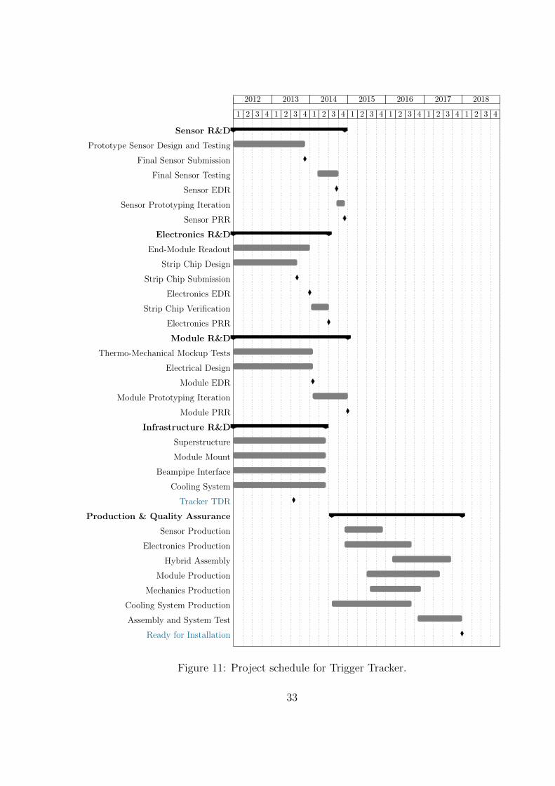
2012 2013 2014 2015 2016 2017 2018
1 2 3 4 1 2 3 4 1 2 3 4 1 2 3 4 1 2 3 4 1 2 3 4 1 2 3 4
Sensor R&D
Prototype Sensor Design and Testing
Final Sensor Submission
Final Sensor Testing
Sensor EDR
Sensor Prototyping Iteration
Sensor PRR
Electronics R&D
End-Module Readout
Strip Chip Design
Strip Chip Submission
Electronics EDR
Strip Chip Verification
Electronics PRR
Module R&D
Thermo-Mechanical Mockup Tests
Electrical Design
Module EDR
Module Prototyping Iteration
Module PRR
Infrastructure R&D
Superstructure
Module Mount
Beampipe Interface
Cooling System
Tracker TDR
Production & Quality Assurance
Sensor Production
Electronics Production
Hybrid Assembly
Module Production
Mechanics Production
Cooling System Production
Assembly and System Test
Ready for Installation
Figure 11: Project schedule for Trigger Tracker.
33

2012 2013 2014 2015 2016 2017 2018
1 2 3 4 1 2 3 4 1 2 3 4 1 2 3 4 1 2 3 4 1 2 3 4 1 2 3 4
Sensor R&D
Sensor Design and Qualification
Sensor EDR
Sensor Prototyping
Sensor PRR
Electronics R&D
Fast Link R&D
Strip Chip Design
Electronics EDR
Strip Chip Submission
Strip Chip Verification
Electronics PRR
Module R&D
Thermo-Mechanical Mockup Tests
Bonding Tests
Electrical Design
Module EDR
Module Prototyping
Module PRR
Infrastructure R&D
Cooling Plant R&D
Tracker TDR
Production & Quality Assurance
Detector Supports
Sensor Production
ASIC Production
Module Production
Assembly
Metrology and System Test
Ready for Installation
Figure 12: Project schedule for Inner Tracker.
34

2012 2013 2014 2015 2016 2017 2018
1 2 3 4 1 2 3 4 1 2 3 4 1 2 3 4 1 2 3 4 1 2 3 4 1 2 3 4
Photo-Detector R&D
SiPM Studies
Scintillating Fibres Qualification
SiPM and Fibres EDR
Detector Prototyping
Photo-Detector PRR
Electronics R&D
ADC Design
Model Simulation
SPECS Studies
Prototype 1 Channel
Prototype 64/128 Channels
Final Prototype
Electronics EDR
Electronics PRR
Module R&D
Geometry Optimisation (Simulation)
Fibre Assembly R&D
Module Design
Shielding and Cooling Scheme Design
Electrical Design
Module EDR
Module Prototyping
Prototype Testing in Cavern
Module PRR
Infrastructure R&D
Cooling Plant R&D
Technology Viability Assessment
Tracker TDR
Production & Quality Assurance
SiPM Production
Fibres Production
Electronics Production
Module Production
System Test
Ready for Installation
Figure 13: Project schedule for Central Tracker.
35

2012 2013 2014 2015 2016 2017 2018
1 2 3 4 1 2 3 4 1 2 3 4 1 2 3 4 1 2 3 4 1 2 3 4 1 2 3 4
Electronics R&D
Upgrade FE Tester
GOL/AUX++ Prototype Board
FEBox++ Validation
10 Prototypes Production and Testing
Electronics EDR
Production of First 10%
Electronics PRR
Module R&D
Tooling Development
Prototype Construction
Construction of First 4 Modules
Module EDR
Production of First 10%
Module PRR
Tracker TDR
Production & Quality Assurance
Module Production
Electronics Production
Assembly and System Test
Ready for Installation
Figure 14: Project schedule for Outer Tracker.
36

2012 2013 2014 2015 2016 2017 2018
1 2 3 4 1 2 3 4 1 2 3 4 1 2 3 4 1 2 3 4 1 2 3 4 1 2 3 4
Photo-Detector and Module R&D
MaPMT Studies
Decision on Photo-Detector Baseline
MaPMT Module Design
MaPMT Module EDR
Prototyping and Testing
MaPMT Module PRR
Electronics R&D
CLARO and Maroc-3 Studies
Decision on ASIC Technology
ASIC Pre-Production
On-Detector R/O Board Prototyping
Electronics EDR
On-Detector R/O Board Pre-Production
MaPMT Module System Tests
Electronics PRR
Infrastructure R&D
Mechanics Design (Detector Mount)
Mechanics EDR
Mechanics Prototyping
Mechanics PRR
RICH TDR
Production & Quality Assurance
MaPMT Production and Testing
MaPMT Module Construction
Detector Mount Construction
Electronics Production and Testing
MaPMT Module Assembly
System Test
Ready for Installation
Figure 15: Project schedule for RICH.
37

2012 2013 2014 2015 2016 2017 2018
1 2 3 4 1 2 3 4 1 2 3 4 1 2 3 4 1 2 3 4 1 2 3 4 1 2 3 4
Electronics R&D
Analog Front-End
Analog Development
COTS Evaluation
Analog Technology Choice
Analog Final Prototype
Analog EDR
Analog Verification
Analog PRR
Front-End Board
First Prototype (Digital Motherboard)
Prototype (8 Channels)
Final Prototype (32 Channels)
Front-End Board EDR
Front-End Board Verification
Front-End Board PRR
Control Board
Control Board Design and Tests
Control Board EDR
Control Board Verification
Control Board PRR
Trigger Validation Board
ECS Firmware
TRIG40 - LLT Firmware
GBT Mezzanines
GBT Mezzanines Design and Tests
GBT Mezzanines EDR
GBT Mezzanines Verification
GBT Mezzanines PRR
Calorimeter TDR
Production & Quality Assurance
Analog Front-End Electronics
Digital Front-End Electronics
Control Board
GBT-SCA Mezzanine
Ready for Installation
Figure 16: Project schedule for Calorimeter.
38

2012 2013 2014 2015 2016 2017 2018
1 2 3 4 1 2 3 4 1 2 3 4 1 2 3 4 1 2 3 4 1 2 3 4 1 2 3 4
Detector R&D
MPWC Validation Tests
Electronics R&D
DAQ Architecture Studies
Firmware Development and Testing
Infrastructure R&D
Shielding Studies (Simulation)
Shielding Design
Muon TDR
Production & Quality Assurance
Shielding Production
MPWC Production (Spares)
System Integration
Ready for Installation
Figure 17: Project schedule for Muon System.
2012 2013 2014 2015 2016 2017 2018
1 2 3 4 1 2 3 4 1 2 3 4 1 2 3 4 1 2 3 4 1 2 3 4 1 2 3 4
Technology R&D
Ethernet Eventbuilder Testing
InfiniBand Eventbuilder Testing
Eventbuilder Technology Choice
HLT Technology Studies
Online TDR
Implementation
TFC & ECS Firmware Development
DAQ Software Development
IT Infrastructure Acquisition
Event-Filter Farm Acquisition
Figure 18: Project schedule for Online.
39

Vertex Locator Cost [kCHF]Pixels Strips
Detector 935 1050Sensors 345 460Flex Hybrid 300 300Module Cooling 290 290
Electronics 3460 2445Front End 1420 410Optical Links 425 420Readout Board 700 700General Electronics 345 345High-Speed Cables 570 570
Infrastructure 1035 1035RF Foil 460 460Motion, Vacuum, Cooling 575 575
5430 4530
Table 5: Cost estimates for Vertex Locator.
Trigger Tracker Cost [kCHF]
Detector 3060Sensors 2300Hybrids & Connectors 760
Electronics 2595Silicon Strip RO chip 900Front End 450Optical Links 345Readout Board 740General Electronics 160
Infrastructure 560Support Structure 230Cooling 330
6215
Table 6: Cost estimate for Trigger Tracker.
3.2 Cost
In the following we present the detailed cost estimates of the individual sub-systems, aswell as the cost of the Common Projects.
As far as the sub-systems are concerned, at this stage we have several technology
40

Inner Tracker Cost [kCHF]
Detector 3760Sensors 3150Hybrid & Flex 610
Electronics 1210Front End 300Optical Links 140Readout Board 230General Electronics 540
Infrastructure 380Mechanics 230Cooling 150
5350
Table 7: Cost estimate for Inner Tracker.
Central Tracker Cost [kCHF]
Detector 2880Fibres 1100Silicon PM 1500Modules 280
Electronics 4020Front End 1550Optical Links 800Readout Board 1270General Electronics 400
Infrastructure 960Support Structure 270Cooling 390Shielding 300
7860
Table 8: Cost estimate for Central Tracker.
options for the detector upgrade and therefore the cost evaluation is given in Tables 5 to13 in kCHF for each option separately, including a contingency of 15%. The cost of bothtechnologies for the VELO, the pixel and strip solution, are given separately in Table 5.The existing vacuum vessel of the present VELO will be reused, but a new RF foil willbe required. The current cooling system will need some modification to provide sufficientcooling power to the new detector. The Trigger Tracker cost estimates are based on asolution with four planes with a finer segmentation in y compared to the existing TT
41

Outer Tracker Cost [kCHF]IT Option CT Option
Detector 1680Straws 760Panels 430Spacers & Wires 490
Electronics 3610 2000Front End 1840 900Optical Links 250 200Readout Board 1400 780General Electronics 120 120
Infrastructure 410Structure adaptation 285Mechanics 125
5700 2000
Table 9: Cost estimates for Outer Tracker.
RICH Cost [kCHF]
Detector 6170Photon Detector 6170
Electronics 2845Front End 1140Optical Links 845Readout Board 700General Electronics 160
Infrastructure 420Photon Detector Support 400Mu-Metal Shield 20
9435
Table 10: Cost estimate for RICH.
(Table 6). The silicon technology for the VELO strip, Trigger Tracker and Inner Trackerwill profit from the common project of the Silicon Strip RO chip and the total cost for thisis included in Table 6. For the Outer Tracker the number of FE electronics boards thatneed replacement for the 40 MHz readout depends on the technology choice of the Trackersystem. The cost for the Inner Tracker is given for the 2-ladder option (Table 7). The3-ladder option would have an identical number of read-out channels and its cost wouldsimply increase proportionally to the increase in sensor surface. In case the Inner Trackerwith a silicon strip solution will be selected, short Outer Tracker modules will have to be
42

Calorimeter Cost [kCHF]
Electronics 1905Front End 690Optical Links 410Readout Board 660Controls Board 65ECS Mezzanine 50Crates 30
1905
Table 11: Cost estimate for Calorimeter.
Muon System Cost [kCHF]
Detector 345Chamber Material 345
Electronics 1270Optical Links 45Readout Board 1015General Electronics 210
Infrastructure 230Shielding 230
1845
Table 12: Cost estimate for Muon System.
built. On the other hand, if the scintillating-fibre Central Tracker were to be selected,with the cost as summarized in Table 8, less of the new FE electronics for the OT wouldbe required. The cost for the OT modules and full electronics production are given inTable 9. The main structure of both RICH detectors and its optical equipment will stayuntouched. The cost table for the RICH systems (Table 10) shows the budget required forthe production of new photon detectors, their mechanical support and 40 MHz readoutelectronics. The Calorimeter (Table 11) requires new front-end electronics to cope with a
Trigger & Readout System Cost [kCHF]
Readout System 1495Low Level Trigger 345
1840
Table 13: Cost estimate for Trigger and Readout System.
43

Common Projects Cost [kCHF]
Online 11170Readout Network 4940Controls Network 905Controls System 930PC Farm 3125Infrastructure 770Timing & Fast Control 500
Common Electronics 2000Optical Fibres & Connectors 500Common Spares 700Power Supplies, Crates, Racks 450DC-DC Converter 350
General Infrastructure 2500Civil Engineering, Building 450Cooling & Ventilation 380General Assembly 230Electrical Power Supply 110Radiation Shielding 200Survey 120Long Distance Cabling 590Safety 300Gas and Fluids Piping 120
15670
Table 14: Cost estimate for Common Projects.
data acquisition at 40 MHz. The cost for the Muon system upgrade is mainly driven bythe number of new readout boards (Table 12). Furthermore, a certain number of muonchambers will be produced for a possible exchange as they might suffer from radiationeffects. The cost of the readout system and the Low Level Trigger for adjusting the datarate at the input of the farm between 1 MHz and 40 MHz are summarized in Table 13.The TFC and ECS part of the readout system amounts to 800 kCHF and is accountedfor in the detector cost.
The Common Projects consist of the online system, common electronics and the gen-eral infrastructure. The cost is detailed in Table 14. The cost of the new farm is basedon 10 MHz input. The size of the farm is expected to increase progressively over thefollowing years after 2018. The common electronics includes the cost for the fibres be-tween patch-panels and connectors. In addition, sufficient spares for the GBT electronics,versatile links, DC-DC converters and power supplies are part of this item. Althougha large fraction of the existing infrastructure will be re-used for the upgrade, almost allsystems will require a modification or partial replacement. The data transmission over
44

detector sub-system countries involved
VELO modules & infrastructure BR, CERN, ES, IE, NL, RU, UK, USelectronics & readout BR, ES, CERN, CN, NL, PL, UK, US
Tracker modules & infrastructure CERN, CH, DE, NL, RU, UK, USelectronics & readout BR, CERN, CH, CN, DE, ES, FR, NL, PL, US
RICH mechanics & infrastructure CERN, IT, UKelectronics & readout CERN, IT, RO, UK
Calo electronics & readout ES, FR, RUMuon chambers IT, RU
electronics & readout ITTrigger electronics & readout BR, CN, FR, IT
Table 15: Expressions of interest to the detector construction, subject to funding.
optical fibres will be mandatory for all detectors and the access to the area upstream ofthe magnet needs to be modified. Detectors such as the Central Tracker or the InnerTracker require new cooling systems including new piping. A large number of opticalfibres will have to be pulled from the underground to the surface up to a new data center.The general and detector safety systems will be upgraded to the new conditions in thecavern. The transport team during operation consists of two staff at present and thiswill have to be increased to six staff during the peak period of the installation. Duringthe installation and after moving the detectors in their final position, a survey team willmeasure the final position of each sub-system.
The overall cost of the LHCb upgrade varies with the choice of the sub-system tech-nology. The core cost of the experiment including the pixel solution for the VELO and anInner Tracker amounts to 53.4 MCHF, while a choice for the VELO strip and a CentralTracker will reduce the overall cost only slightly to 51.3 MCHF. Any other combination oftechnologies will stay in-between these values. For the Particle Identification system, i.e.the RICH, Calorimeter and Muon detectors, we foresee an additional reserve of 3.5 MCHFin order to account for possible modifications of some of the detector elements to complywith a luminosity of L = 2× 1033cm−2s−1. Including this reserve, the total upgrade costamounts to 57 MCHF.
3.3 Expressions of interest
Subject to funding, Table 15 summarizes the expressions of interest of the countries inthe LHCb collaboration to the construction of the different detector sub-systems, whereasTable 16 lists the participating institutes. In addition to contributing to the core detectorcost, all institutes will participate with manpower and common funds to the CommonProjects consisting of the Online, Common Electronics, Infrastructure and Computing.The common funds as detailed in Table 14 amount to ∼ 30% of the total upgrade cost.
45

Code Country Institutes
BR Brasil CBPF1, UFRL2, PUC-Rio3
CERN CERN CERN38
CN China Tsinghua Univ.4
CH Switzerland EPFL Lausanne39, Univ. Zurich40
DE Germany TU Dortmund10, MPIK Heidelberg11, Uni Heidelberg12,Uni Rostock13
ES Spain Univ. Barcelona36, Univ. Santiago de Compostela37
FR France CNRS/IN2P3: LAPP5, LPC6, CPPM7, LAL8, LPNHE9
IE Ireland Univ. College Dublin14
IT Italy INFN: Bari15, Bologna16, Cagliari17, Ferrara18, Firenze19,Frascati20, Genova21, Milano22, Roma Tor Vergata23,Roma La Sapienza24
NL Netherlands Nikhef41, VU Univ. Amsterdam42
PK Pakistan Lahore Univ.25
PL Poland Henry Niewodniczanski Inst. Krakow26, AGH Univ. Krakow27,Soltan Inst. Warsaw28
RO Romania Horia Hulubei Nat. Inst. Bucharest29
RU Russia PNPI30, ITEP31, SINP MSU32, INR RAN33,SB RAS Novosibirsk Univ.34, IHEP35
UA Ukraine NSC KIPT43, KINR44
UK Great Britain Birmingham45, Bristol46, Cambridge47, Warwick48,STFC RAL49, Edinburgh50, Glasgow51, Liverpool52,Imperial College London53, Manchester54, Oxford55
US United States Cincinnati56, Syracuse57
Table 16: List of participating institutes, with reference to the authorlist.
46

References
[1] LHCb collaboration, Letter of Intent for the LHCb Upgrade, CERN-LHCC-2011-001,LHCC-I-018
[2] LHCb collaboration, R. Aaij et al., Strong constraints on the rare decays B0s → µ+µ−
and B0 → µ+µ−, arXiv:1203.4493
[3] LHCb collaboration, R. Aaij et al., Differential branching fraction and angularanalysis of the decay B0 → K∗0µ+µ−, Phys. Rev. Lett. 108 (2012) 181806,arXiv:1112.3515
[4] LHCb collaboration, R. Aaij et al., Measurement of the CP -violating phase φs in thedecay B0
s → J/ψφ, Phys. Rev. Lett. 108 (2012) 101803, arXiv:1112.3183
[5] LHCb collaboration, R. Aaij et al., Evidence for CP violation in time-integratedD0 → h−h+ decay rates, Phys. Rev. Lett. 108 (2012) 111602, arXiv:1112.0938
[6] LHCb collaboration, R. Aaij et al., First evidence of direct CP violation incharmless two-body decays of B0
s mesons, Phys. Rev. Lett. 108 (2012) 201601,arXiv:1202.6251
[7] LHCb collaboration, R. Aaij et al., Inclusive W and Z production in the forwardregion at
√s = 7 TeV, arXiv:1204.1620
[8] LHCb collaboration, R. Aaij et al., and invited theorists. Implications of LHCb mea-surements and future prospects, LHCb-PUB-2012-006, in preparation
[9] LHCb collaboration, Tagged time-dependent angular analysis of B0s → J/ψφ decays
at LHCb, LHCb-CONF-2012-002
[10] LHCb collaboration, R. Aaij et al., Measurement of φs in B0s → J/ψπ+π− decays,
arXiv:1204.5675
[11] E. Lunghi and A. Soni, Possible evidence for the breakdown of the CKM-paradigm ofCP -violation, Phys. Lett. B697 (2011) 323, arXiv:1010.6069
[12] LHCb collaboration, R. Aaij et al., First observation of the decay B0s → K∗0K∗0,
Phys. Lett. B709 (2012) 50, arXiv:1111.4183
[13] LHCb collaboration, R. Aaij et al., Measurement of the polarization amplitudes andtriple product asymmetries in the B0
s → φφ decay, arXiv:1204.2813
[14] LHCb collaboration, Differential branching fraction and angular analysis of the B0 →K∗0µ+µ− decay, LHCb-CONF-2012-008
[15] LHCb collaboration, R. Aaij et al., Measurement of the isospin asymmetry in B →K(∗)µ+µ− decays, arXiv:1205.3422
47

[16] LHCb collaboration, First observation of B+ → π+µ+µ−, LHCb-CONF-2012-006
[17] LHCb collaboration, R. Aaij et al., Observation of CP violation in B+ → DK+
decays, arXiv:1203.3662
[18] Heavy Flavour Averaging Group, D. Asner et al., Averages of b-hadron, c-hadron,and τ -lepton Properties, arXiv:1010.1589, updated results and plots available at:http://www.slac.stanford.edu/xorg/hfag/
[19] CKMfitter Group, J. Charles et al., CP violation and the CKM matrix:Assessing the impact of the asymmetric B factories, Eur. Phys. J. C41,(2005) 1, arXiv:hep-ph/0406184, updated results and plots available at:http://ckmfitter.in2p3.fr
[20] UTfit Collaboration, M. Bona et al., The 2004 UTfit Collaboration Reporton the Status of the Unitarity Triangle in the Standard Model, JHEP 07(2005) 028, arXiv:hep-ph/0501199, updated results and plots available at:http://www.utfit.org/UTfit/
[21] LHCb collaboration, R. Aaij et al., Measurement of b hadron production fractions in7 TeV pp collisions, Phys. Rev. D85 (2012) 032008, arXiv:1111.2357
[22] LHCb collaboration, R. Aaij et al., Observation of double charm production involvingopen charm in pp collisions at
√s=7 TeV, arXiv:1205.0975
[23] LHCb collaboration, Search for (Higgs-like) bosons decaying into long-lived exoticparticles, LHCb-CONF-2012-014
[24] B. Schmidt, for the LHCb collaboration, Will LHCb run in the HL-LHC era?, Pro-ceedings of the LHC Performance Workshop, Chamonix 2012, and references therein
[25] B. Holzer et al., Optics and Lattice optimizations for the LHC upgrade project, Pro-ceedings of IPAC 2012, New Orleans (Lousiana), May 2012, in preparation
[26] A. Affolder, Charge Collection Efficiencies of Silicon Detectors after Reactor Neutron,Pion and Proton Doses up to 2.2×10¹⁶ neq cm−2, 14th RD50 Workshop on Radiationhard semiconductor devices for very high luminosity colliders, Freiburg, Germany,June 2009
[27] L. Spiegel, A tracker/trigger design for an upgraded CMS Tracker, Second Interna-tional Conference on Technology and Instrumentation in Particle Physics, Chicago,United States, June 2011
[28] Y. Ikegami et al., R&D towards the module and service structure design for the AT-LAS inner tracker at the super LHC (SLHC), in Proceedings of the Topical Workshopon Electronics for Particle Physics 2010 (TWEPP-10), JINST 5 (2010) C12056
48

[29] M. Oinonen et al., Alice Silicon Strip Detector Module Assembly with Single-PointTAB Interconnections, in Proceedings of the 11th Workshop on Electronics for LHCand Future Experiments, Heidelberg, Germany, 12-16 Sep 2005
[30] P. Moreira et al., The GBT project, in Proceedings of the Topical Workshop onElectronics for Particle Physics 2009 (TWEPP-09), CERN-2009-006 pp. 342-346
[31] E. Picatoste et al., Low noise front end ICECAL ASIC for the upgrade of the LHCbcalorimeter, in Proceedings of the Topical Workshop on Electronics for ParticlePhysics 2011 (TWEPP-11), JINST 7 (2012) C01080
[32] D. Breton and D. Charlet, SPECS: the Serial Protocol for the Experiment ControlSystem of LHCb, LHCb-2003-004
[33] M. Anelli, et al., High-rate performance of the MWPCs for the LHCb Muon System,Nucl. Instrum. Meth. A593 (2008) 319
[34] M. Anelli, et al., High radiation tests of the MWPCs for the LHCb Muon System,Nucl. Instrum. Meth. A599 (2009) 171
[35] V. Suvorov, T. Schneider, B. Schmidt, W. Riegler, A. Kashchuk and D. Hutchcroft,First results of an aging test of a full scale MWPC prototype for the LHCb MuonSystem, Nucl. Instrum. Meth. A515 (2003) 220
[36] PICMG, PICMG 3.0 Revision 3.0 AdvancedTCA Base Specification,http://www.picmg.org
49


ISBN 978-92-9083-374-1


