Precision Cooling For Business-Critical Continuity™ Liebert ® CRV ™ Installation, Operation and Maintenance Manual–60Hz, Air-Cooled, Water/Glycol-Cooled and Chilled Water DATA CENTER SOLUTIONS For More Information: (866) 787-3271 [email protected]
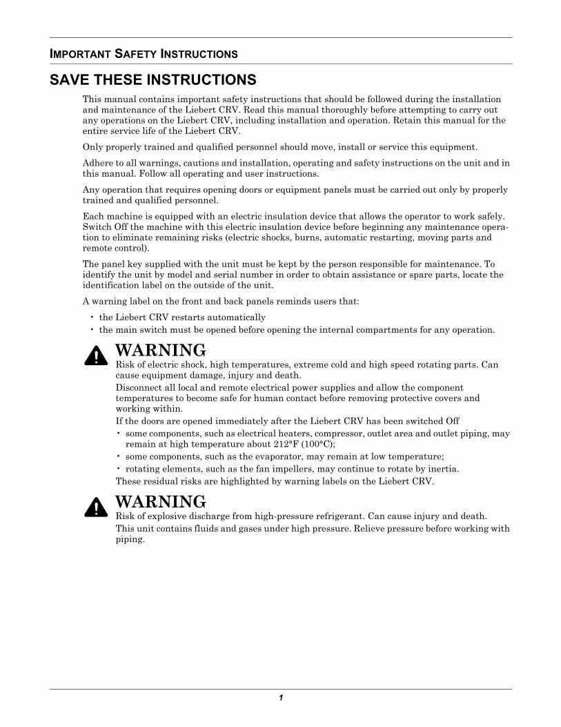
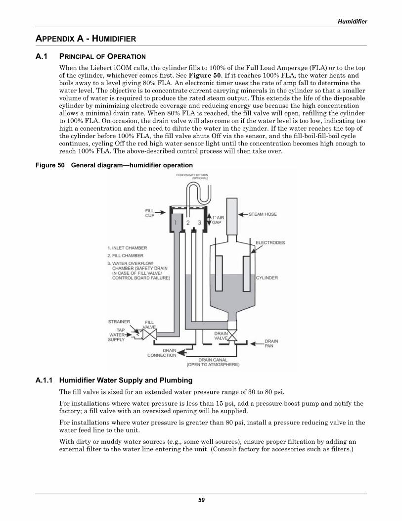
SAVE THESE INSTRUCTIONSThis manual contains important safety instructions that should be followed during the installation and maintenance of the Liebert CRV. Read this manual thoroughly before attempting to carry out any operations on the Liebert CRV, including installation and operation. Retain this manual for the entire service life of the Liebert CRV.
Only properly trained and qualified personnel should move, install or service this equipment.
Adhere to all warnings, cautions and installation, operating and safety instructions on the unit and in this manual. Follow all operating and user instructions.
Any operation that requires opening doors or equipment panels must be carried out only by properly trained and qualified personnel.
Each machine is equipped with an electric insulation device that allows the operator to work safely. Switch Off the machine with this electric insulation device before beginning any maintenance opera-tion to eliminate remaining risks (electric shocks, burns, automatic restarting, moving parts and remote control).
The panel key supplied with the unit must be kept by the person responsible for maintenance. To identify the unit by model and serial number in order to obtain assistance or spare parts, locate the identification label on the outside of the unit.
A warning label on the front and back panels reminds users that:
• the Liebert CRV restarts automatically• the main switch must be opened before opening the internal compartments for any operation.
! WARNINGRisk of electric shock, high temperatures, extreme cold and high speed rotating parts. Can cause equipment damage, injury and death.Disconnect all local and remote electrical power supplies and allow the component temperatures to become safe for human contact before removing protective covers and working within.If the doors are opened immediately after the Liebert CRV has been switched Off• some components, such as electrical heaters, compressor, outlet area and outlet piping, may
remain at high temperature about 212°F (100°C);• some components, such as the evaporator, may remain at low temperature;• rotating elements, such as the fan impellers, may continue to rotate by inertia. These residual risks are highlighted by warning labels on the Liebert CRV.
! WARNINGRisk of explosive discharge from high-pressure refrigerant. Can cause injury and death.This unit contains fluids and gases under high pressure. Relieve pressure before working with piping.
2
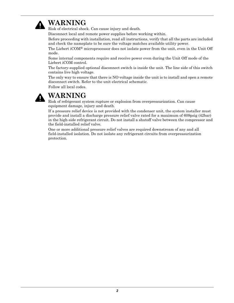
! WARNINGRisk of electrical shock. Can cause injury and death.Disconnect local and remote power supplies before working within.Before proceeding with installation, read all instructions, verify that all the parts are included and check the nameplate to be sure the voltage matches available utility power.The Liebert iCOM® microprocessor does not isolate power from the unit, even in the Unit Off mode.Some internal components require and receive power even during the Unit Off mode of the Liebert iCOM control.The factory-supplied optional disconnect switch is inside the unit. The line side of this switch contains live high voltage.The only way to ensure that there is NO voltage inside the unit is to install and open a remote disconnect switch. Refer to the unit electrical schematic.Follow all local codes.
! WARNINGRisk of refrigerant system rupture or explosion from overpressurization. Can cause equipment damage, injury and death.If a pressure relief device is not provided with the condenser unit, the system installer must provide and install a discharge pressure relief valve rated for a maximum of 609psig (42bar) in the high-side refrigerant circuit. Do not install a shutoff valve between the compressor and the field-installed relief valve. One or more additional pressure relief valves are required downstream of any and all field-installed isolation. Do not isolate any refrigerant circuits from overpressurization protection.
Liebert CRV Component Location
3
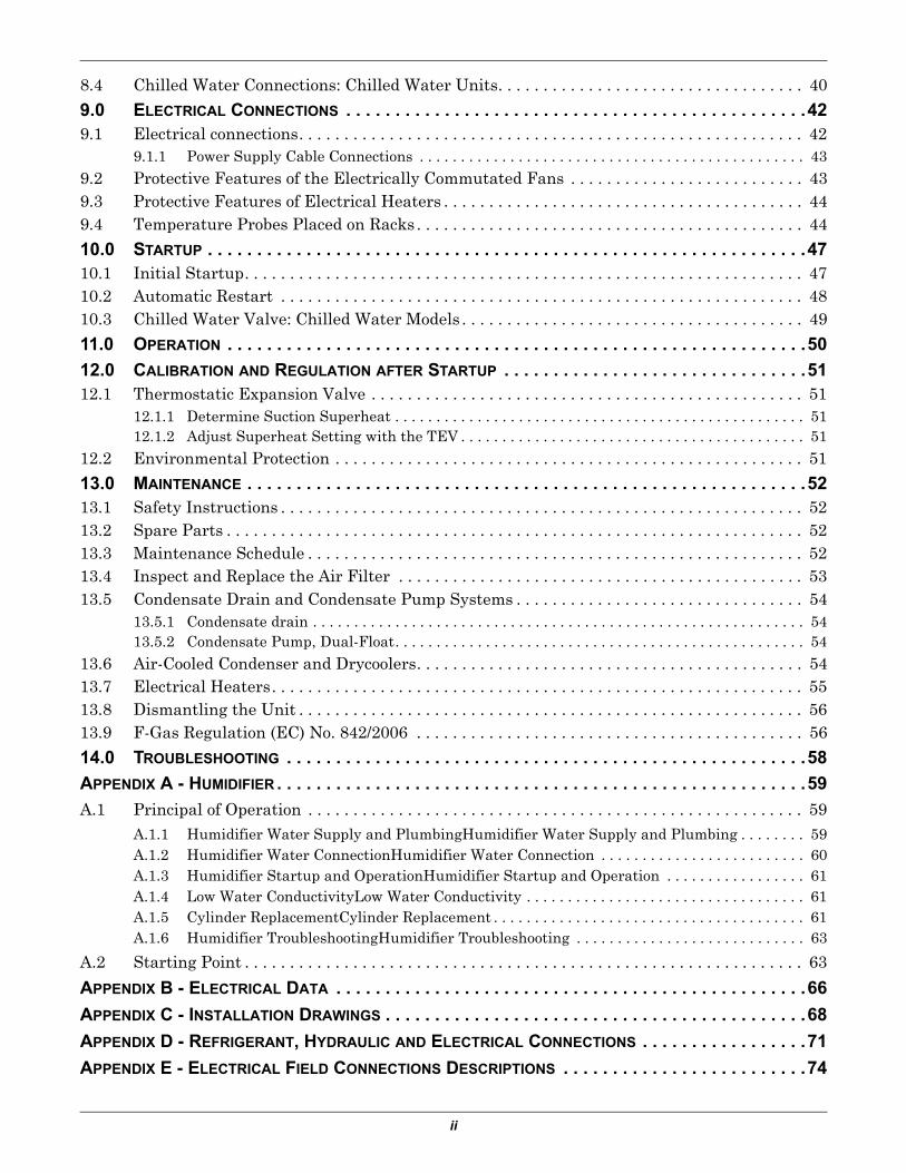
1.0 LIEBERT CRV COMPONENT LOCATION
Figure 1 Component location, common components—All models
Figure 2 Component location - Liebert CR035, CR020 air-cooled units
1 Liebert iCOM control display
2 Electric box
3 Evaporator / CW coil
4 Condensate pump
5 Electric heaters
6 Humidifier distributor
7 Top humidifier supply, condensate pump drain
8 Drain trays, two places
9 EC plug fans
10 Bottom electrical entrance
11 Serial tag inside door
12 Bottom condensate pump drain
13 Top electrical entrance
14 Supply air temperature sensor location (sensor not shown)
1
2
11
3
12
10
4
8
8
6
5
9
13
7
14
FrontRear
81
10
3
4
7
9
2
5
6
11
12
13
1 Thermostatic expansion valve
2 Solenoid valve
3 Sight glass
4 Filter dryer
7 Humidity/Temp. sensor
8 Humidifier
9 Top refrigerant connections
10 Bottom refrigerant connections
11 Bottom humidifier supply
12 Air filters
13 Bottom drain
Rear
Front
Liebert CRV Component Location
4
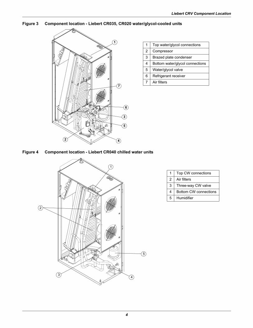
Figure 3 Component location - Liebert CR035, CR020 water/glycol-cooled units
Figure 4 Component location - Liebert CR040 chilled water units
2
3
1
4
5
6
7
1 Top water/glycol connections
2 Compressor
3 Brazed plate condenser
4 Bottom water/glycol connections
5 Water/glycol valve
6 Refrigerant receiver
7 Air filters
2
3
1
5
4
1 Top CW connections
2 Air filters
3 Three-way CW valve
4 Bottom CW connections
5 Humidifier
Introduction
5
2.0 INTRODUCTION
2.1 Product DescriptionThe Liebert CRV is a precision cooling unit available in compressorized (air-, water-, or glycol-cooled) and chilled water configurations to be installed within a row of high-density computing racks in a “hot aisle-cold aisle” configuration.
Air enters the rear of the Liebert CRV from the hot aisle, is filtered, cooled and conditioned, then dis-charged into the cold aisle. The Liebert CRV provides all the necessary functions of a standard preci-sion air conditioner, including cooling, heating, humidification, dehumidification, air filtration, condensate management, temperature control, alarm functions and data communication. The Liebert CRV is optimized for maximum cooling capacity in a minimal footprint.
Figure 5 Liebert CRV, front and rear views
RearFront
Inspection and Unpacking
6
3.0 INSPECTION AND UNPACKING
NOTICERisk of overhead interference. Can cause unit and/or structural damage.The unit may be too tall to fit through a doorway while on the pallet. Measure the unit and doorway heights and refer to the installation plans prior to moving the unit to verify clearances.
NOTICERisk of unit damage if improperly stored.Keep the unit upright, indoors and protected from dampness, freezing temperatures and contact damage.
3.1 Equipment InspectionAfter the Liebert CRV unit arrives and before it is unpacked, verify that the delivered equipment matches the bill of lading. Examine the packaging for any signs of mishandling or damage. Inspect all items for damage, visible or concealed. Report any damage immediately to the carrier and file a dam-age claim. Send a copy of the claim to Emerson Network Power or your Emerson representative.
3.1.1 Packing MaterialAll material used to package this unit is recyclable. Please save this material for future use or dispose of it appropriately.
3.2 HandlingFigure 6 Liebert CRV center of gravity
! WARNINGRisk of top-heavy unit falling over. Can cause equipment damage, personal injury and death.Read all of the following instructions before attempting to move, lift or remove packaging from the Liebert CRV.
! CAUTIONRisk of sharp edges, splinters and exposed fasteners. Can cause personal injury.Only properly trained and qualified personnel wearing appropriate safety headgear, gloves, shoes and glasses should attempt to move, lift or remove packaging from the Liebert CRV or prepare the unit for installation.
R
Z
Y
X
Inspection and Unpacking
7
• Always keep the packaged Liebert CRV upright and never leave it outdoors.• If possible, transport the Liebert CRV using a forklift or pallet jack. Otherwise, use a crane with
belts or cables and spreader bars to protect the unit's sides from damage.• If using a forklift or pallet jack, make sure the forks (if adjustable) are spread to the widest dis-
tance that will fit under the skid. Also, ensure the fork length is suitable for the unit length.• When moving the packaged unit, do not lift it any higher than 6" (152 mm) off the ground. Exer-
cise great care if the unit must be lifted higher than 6" (152 mm); any personnel not directly involved in lifting the unit must be at least 20ft (5m) away from the unit.
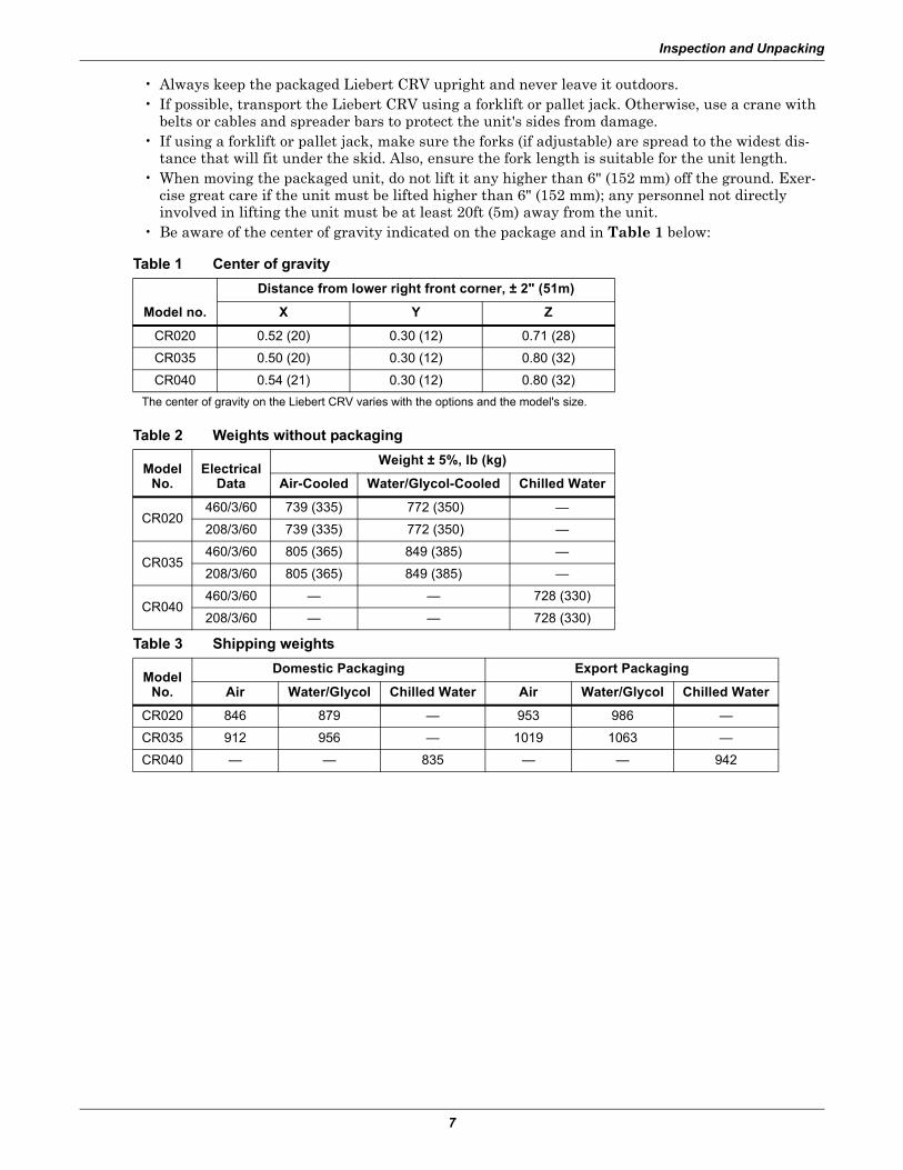
• Be aware of the center of gravity indicated on the package and in Table 1 below:
Table 1 Center of gravity
Model no.
Distance from lower right front corner, ± 2" (51m)
X Y Z
CR020 0.52 (20) 0.30 (12) 0.71 (28)
CR035 0.50 (20) 0.30 (12) 0.80 (32)
CR040 0.54 (21) 0.30 (12) 0.80 (32)The center of gravity on the Liebert CRV varies with the options and the model's size.
Table 2 Weights without packaging
ModelNo.
ElectricalData
Weight ± 5%, lb (kg)
Air-Cooled Water/Glycol-Cooled Chilled Water
CR020460/3/60 739 (335) 772 (350) —
208/3/60 739 (335) 772 (350) —
CR035460/3/60 805 (365) 849 (385) —
208/3/60 805 (365) 849 (385) —
CR040460/3/60 — — 728 (330)
208/3/60 — — 728 (330)
Table 3 Shipping weights
ModelNo.
Domestic Packaging Export Packaging
Air Water/Glycol Chilled Water Air Water/Glycol Chilled Water
CR020 846 879 — 953 986 —
CR035 912 956 — 1019 1063 —
CR040 — — 835 — — 942
Inspection and Unpacking
8
3.2.1 Handling the Unit While it is PackagedFigure 7 Recommended unit handling equipment
• If possible, transport the packaged Liebert CRV using a forklift or pallet jack; otherwise, use a crane with slings and spreader bars.
• If using a fork lift or pallet jack, make sure the forks (if adjustable) are spread to the widest allow-able distance that fits under the pallet. Make sure the fork length is suitable for the unit length.
• When moving the packaged unit with a forklift or pallet jack, lift the unit from either end of the pallet.
• When handling the packaged Liebert CRV with a forklift or pallet jack, do not lift it any higher than 2" to 4" (51mm to 102mm) off the ground. Any personnel not directly involved in lifting the unit must be at least 12 ft (3.7m) from the unit.
• Exercise great care if the unit must be lifted higher than 4" (102mm); any personnel not directly involved in lifting the unit must be at least 20 ft (5 m) away from the unit.
3.3 Unpacking the Liebert CRV1. Remove the exterior stretch wrap packaging material from the unit, exposing the protective
corner and side packaging planks.2. Remove the corner and side packaging planks from the unit, exposing the bag over the unit. The
bag may remain in place for dust and panel protection, or removed for immediate unit installation.
3. Remove the bag when ready to install the unit.
Figure 8 Unpacking the Liebert CRV
Spreader Bars and Slings
Piano JacksPalletJack
Forklift
Step 1 Step 2 Step 3
Inspection and Unpacking
9
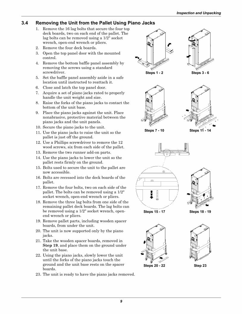
3.4 Removing the Unit from the Pallet Using Piano Jacks1. Remove the 16 lag bolts that secure the four top
deck boards, two on each end of the pallet. The lag bolts can be removed using a 1/2" socket wrench, open-end wrench or pliers.
2. Remove the four deck boards.3. Open the top panel door with the mounted
control.4. Remove the bottom baffle panel assembly by
removing the screws using a standard screwdriver.
5. Set the baffle panel assembly aside in a safe location until instructed to reattach it.
6. Close and latch the top panel door.7. Acquire a set of piano jacks rated to properly
handle the unit weight and size.8. Raise the forks of the piano jacks to contact the
bottom of the unit base.9. Place the piano jacks against the unit. Place
nonabrasive, protective material between the piano jacks and the unit panels.
10. Secure the piano jacks to the unit.11. Use the piano jacks to raise the unit so the
pallet is just off the ground.12. Use a Phillips screwdriver to remove the 12
wood screws, six from each side of the pallet.13. Remove the two runner add-on parts.14. Use the piano jacks to lower the unit so the
pallet rests firmly on the ground.15. Bolts used to secure the unit to the pallet are
now accessible.16. Bolts are recessed into the deck boards of the
pallet.17. Remove the four bolts, two on each side of the
pallet. The bolts can be removed using a 1/2" socket wrench, open-end wrench or pliers.
18. Remove the three lag bolts from one side of the remaining pallet deck boards. The lag bolts can be removed using a 1/2" socket wrench, open-end wrench or pliers.
19. Remove pallet parts, including wooden spacer boards, from under the unit.
20. The unit is now supported only by the piano jacks.
21. Take the wooden spacer boards, removed in Step 19, and place them on the ground under the unit base.
22. Using the piano jacks, slowly lower the unit until the forks of the piano jacks touch the ground and the unit base rests on the spacer boards.
23. The unit is ready to have the piano jacks removed.
Steps 1 - 2 Steps 3 - 6
Steps 7 - 10 Steps 11 - 14
Steps 15 - 17 Steps 18 - 19
Steps 20 - 22 Step 23
Inspection and Unpacking
10
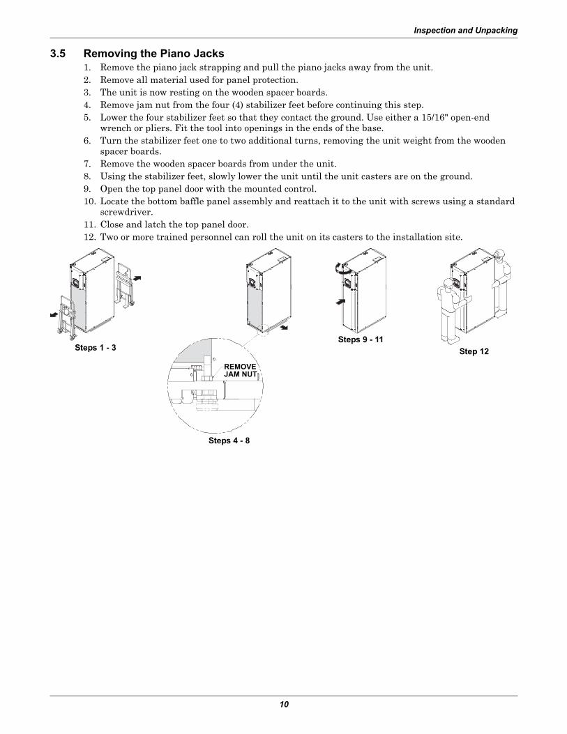
3.5 Removing the Piano Jacks1. Remove the piano jack strapping and pull the piano jacks away from the unit.2. Remove all material used for panel protection.3. The unit is now resting on the wooden spacer boards.4. Remove jam nut from the four (4) stabilizer feet before continuing this step.5. Lower the four stabilizer feet so that they contact the ground. Use either a 15/16" open-end
wrench or pliers. Fit the tool into openings in the ends of the base.6. Turn the stabilizer feet one to two additional turns, removing the unit weight from the wooden
spacer boards.7. Remove the wooden spacer boards from under the unit.8. Using the stabilizer feet, slowly lower the unit until the unit casters are on the ground.9. Open the top panel door with the mounted control.10. Locate the bottom baffle panel assembly and reattach it to the unit with screws using a standard
screwdriver.11. Close and latch the top panel door.12. Two or more trained personnel can roll the unit on its casters to the installation site.
Steps 4 - 8
Steps 9 - 11Step 12Steps 1 - 3
REMOVEJAM NUT
Prepare the Liebert CRV for Installation
11
4.0 PREPARE THE LIEBERT CRV FOR INSTALLATION
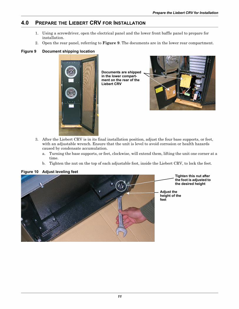
1. Using a screwdriver, open the electrical panel and the lower front baffle panel to prepare for installation.
2. Open the rear panel, referring to Figure 9. The documents are in the lower rear compartment.
Figure 9 Document shipping location
3. After the Liebert CRV is in its final installation position, adjust the four base supports, or feet, with an adjustable wrench. Ensure that the unit is level to avoid corrosion or health hazards caused by condensate accumulation.a. Turning the base supports, or feet, clockwise, will extend them, lifting the unit one corner at a
time.b. Tighten the nut on the top of each adjustable foot, inside the Liebert CRV, to lock the feet.
Figure 10 Adjust leveling feet
Documents are shipped in the lower compart-ment on the rear of the Liebert CRV
Adjust the height of the feet
Tighten this nut after the foot is adjusted to the desired height
Prepare the Liebert CRV for Installation
12
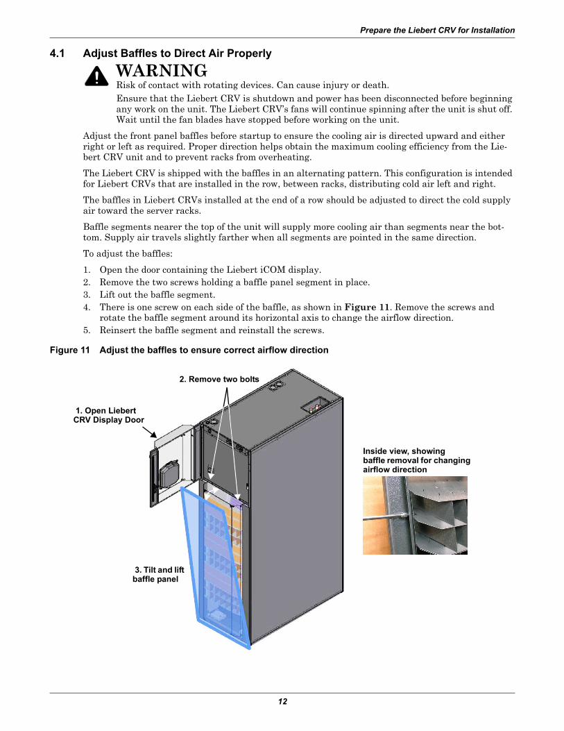
4.1 Adjust Baffles to Direct Air Properly
Adjust the front panel baffles before startup to ensure the cooling air is directed upward and either right or left as required. Proper direction helps obtain the maximum cooling efficiency from the Lie-bert CRV unit and to prevent racks from overheating.
The Liebert CRV is shipped with the baffles in an alternating pattern. This configuration is intended for Liebert CRVs that are installed in the row, between racks, distributing cold air left and right.
The baffles in Liebert CRVs installed at the end of a row should be adjusted to direct the cold supply air toward the server racks.
Baffle segments nearer the top of the unit will supply more cooling air than segments near the bot-tom. Supply air travels slightly farther when all segments are pointed in the same direction.
To adjust the baffles:
1. Open the door containing the Liebert iCOM display.2. Remove the two screws holding a baffle panel segment in place. 3. Lift out the baffle segment.4. There is one screw on each side of the baffle, as shown in Figure 11. Remove the screws and
rotate the baffle segment around its horizontal axis to change the airflow direction.5. Reinsert the baffle segment and reinstall the screws.
Figure 11 Adjust the baffles to ensure correct airflow direction
! WARNINGRisk of contact with rotating devices. Can cause injury or death.Ensure that the Liebert CRV is shutdown and power has been disconnected before beginning any work on the unit. The Liebert CRV’s fans will continue spinning after the unit is shut off. Wait until the fan blades have stopped before working on the unit.
1. Open Liebert CRV Display Door
Inside view, showingbaffle removal for changing airflow direction
2. Remove two bolts
3. Tilt and lift baffle panel
Liebert iCOM Control
13
5.0 LIEBERT ICOM CONTROL
The Liebert CRV is equipped with the most advanced Liebert iCOM control system. Each Liebert CRV contains a return air temperature and humidity sensor, supply air temperature sensor and three remote rack sensors. Up to an additional 7 remote rack sensors can be added to the sensor network. Each rack sensor takes two temperature readings and reports either the average or the maximum temperature of the two sensors.
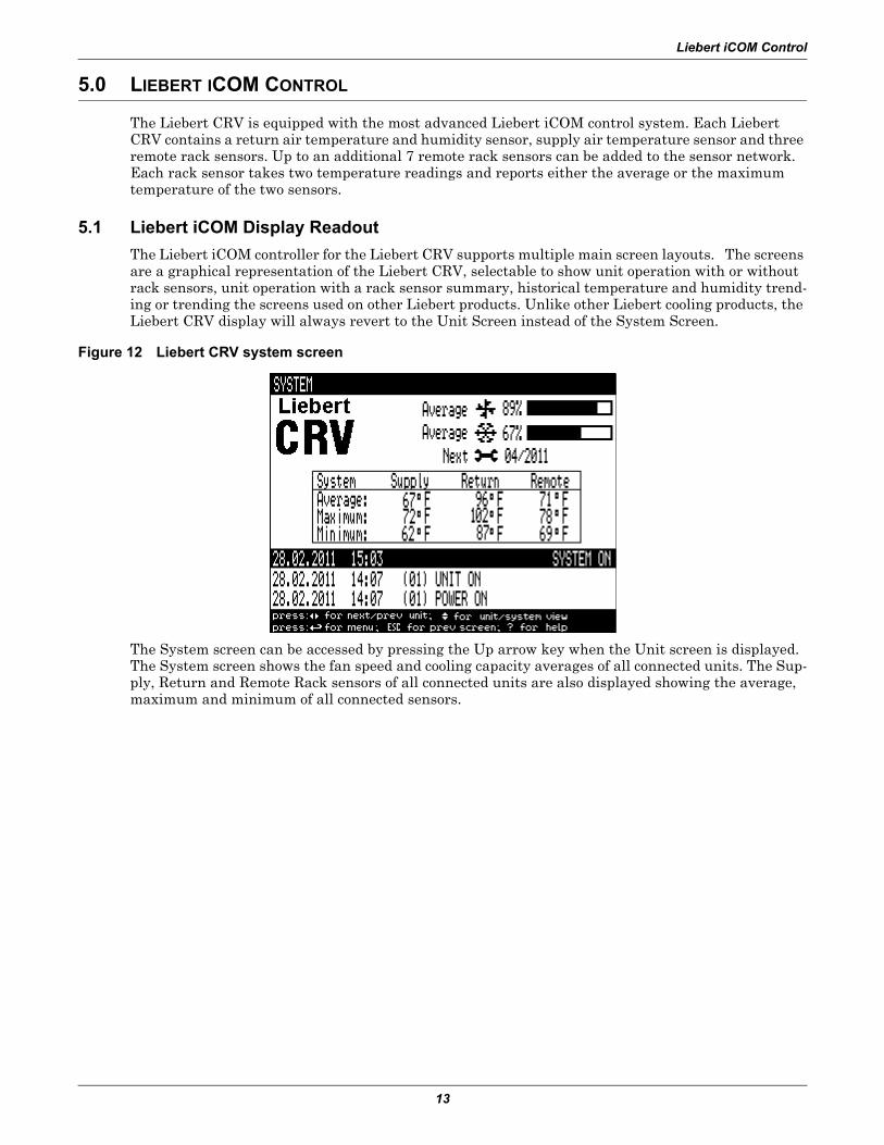
5.1 Liebert iCOM Display ReadoutThe Liebert iCOM controller for the Liebert CRV supports multiple main screen layouts. The screens are a graphical representation of the Liebert CRV, selectable to show unit operation with or without rack sensors, unit operation with a rack sensor summary, historical temperature and humidity trend-ing or trending the screens used on other Liebert products. Unlike other Liebert cooling products, the Liebert CRV display will always revert to the Unit Screen instead of the System Screen.
Figure 12 Liebert CRV system screen
The System screen can be accessed by pressing the Up arrow key when the Unit screen is displayed. The System screen shows the fan speed and cooling capacity averages of all connected units. The Sup-ply, Return and Remote Rack sensors of all connected units are also displayed showing the average, maximum and minimum of all connected sensors.
Liebert iCOM Control
14
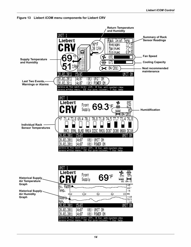
Figure 13 Liebert iCOM menu components for Liebert CRV
Supply Temperatureand Humidity
Last Two Events, Warnings or Alarms
Individual RackSensor Temperatures
Historical Supply Air TemperatureGraph
Historical Supply Air HumidityGraph
Fan Speed
Return Temperatureand Humidity
Cooling Capacity
Next recommended maintenance
Summary of Rack Sensor Readings
Humidification
Liebert iCOM Control
15
5.2 Liebert iCOM Remote Rack Sensor ConfigurationThere are two steps to setting up a remote rack sensor:
• The DIP switches of the remote rack sensor must be configured to have a unique ID• The Liebert iCOM must be used to set the remote rack sensor as either a controlling sensor or as
a reference sensor.
Table 4 Keyboard icons and functionsIcon Key Name Function
On/Off Key Controls the operational state of the cooling unit.
Alarm Key Silences an alarm.
Help Key Accesses integrated Help menus.
ESCape Key Returns to the previous display view.
Enter Key Confirms all selections and selects icons or text.
Increase Key(Up Arrow) Moves upward in a menu or increases the value of a selected parameter.
Decrease Key(Down Arrow) Moves downward in a menu or reduces the value of a selected parameter.
Left and RightArrow Keys Navigates through text and sections of the display.
Upper LED
Blinking Red—Active, unacknowledged alarm exists
Solid Red—Active, acknowledged alarm exists
Lower LED
Amber—Power is available to the unit; unit is NOT operating
Green—Unit is operating with no alarms
?
ESC
Liebert iCOM Control
16
5.2.1 Setting the Remote Rack Sensor AddressRemove the cap on the rear of the plastic sensor housing. This cap protects the switch selection (SW1) that sets the node address of the sensor. Each sensor must have a unique address to communicate correctly with the Liebert CRV. Follow Table 5 until all connected sensors have been configured.
Switches 1 through 6 are used to configure the node address.
Figure 14 Remote rack sensor access point
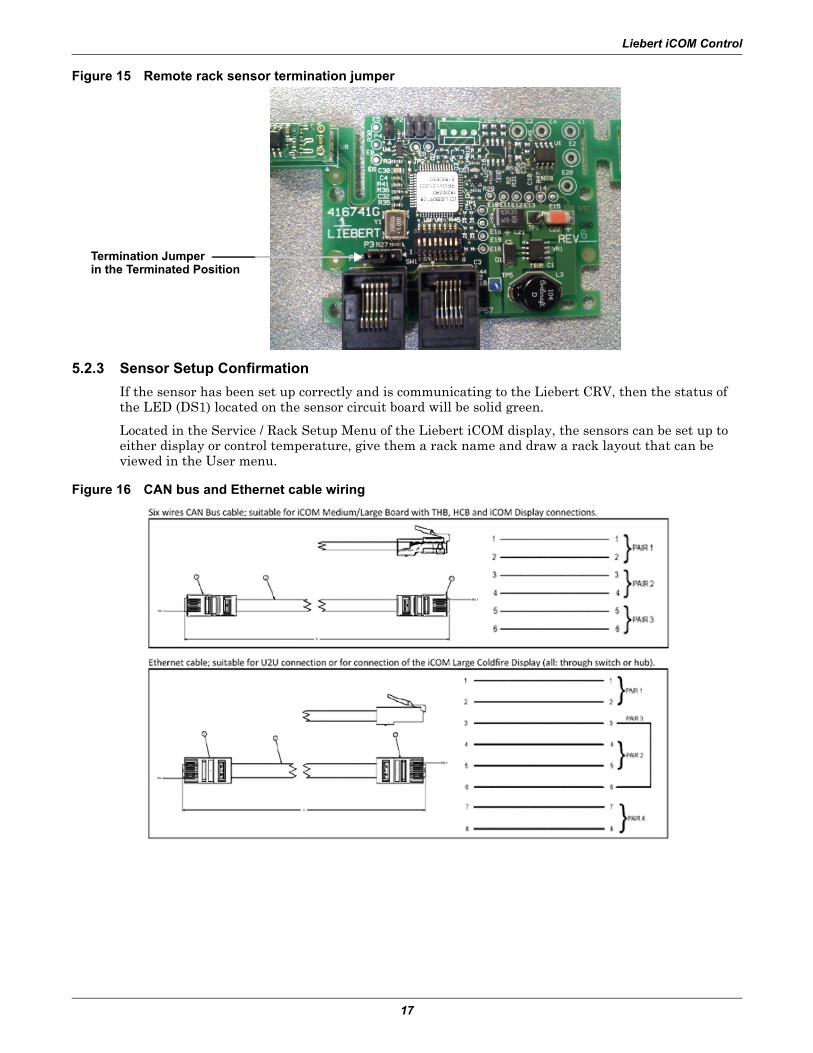
5.2.2 CAN Bus TerminationThe last or end sensor of the sensor network requires a jumper on the circuit board moved for proper termination of the sensor network. This termination helps to reduce noise and reflections on the sen-sor network. The sensor at the physical end of the network is the sensor with only one cable plugged into it.
To correctly position the termination jumper:
1. Unplug all connections to the sensor.2. Remove the three screws holding the sensor housing together.3. Locate the P3 jumper directly above the left network connection port.4. Change the jumper selection from Pins 1 and 2 to Pins 2 and 3 (see Figure 15).
5.2.3 Sensor Setup ConfirmationIf the sensor has been set up correctly and is communicating to the Liebert CRV, then the status of the LED (DS1) located on the sensor circuit board will be solid green.
Located in the Service / Rack Setup Menu of the Liebert iCOM display, the sensors can be set up to either display or control temperature, give them a rack name and draw a rack layout that can be viewed in the User menu.
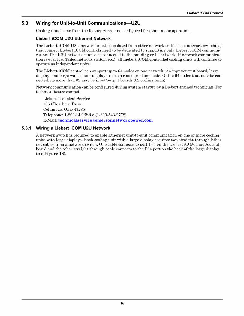
Figure 16 CAN bus and Ethernet cable wiring
Termination Jumperin the Terminated Position
Liebert iCOM Control
18
5.3 Wiring for Unit-to-Unit Communications—U2UCooling units come from the factory-wired and configured for stand-alone operation.
Liebert iCOM U2U Ethernet NetworkThe Liebert iCOM U2U network must be isolated from other network traffic. The network switch(es) that connect Liebert iCOM controls need to be dedicated to supporting only Liebert iCOM communi-cation. The U2U network cannot be connected to the building or IT network. If network communica-tion is ever lost (failed network switch, etc.), all Liebert iCOM-controlled cooling units will continue to operate as independent units.
The Liebert iCOM control can support up to 64 nodes on one network. An input/output board, large display, and large wall-mount display are each considered one node. Of the 64 nodes that may be con-nected, no more than 32 may be input/output boards (32 cooling units).
Network communication can be configured during system startup by a Liebert-trained technician. For technical issues contact:
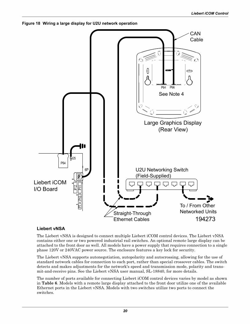
5.3.1 Wiring a Liebert iCOM U2U NetworkA network switch is required to enable Ethernet unit-to-unit communication on one or more cooling units with large displays. Each cooling unit with a large display requires two straight-through Ether-net cables from a network switch. One cable connects to port P64 on the Liebert iCOM input/output board and the other straight-through cable connects to the P64 port on the back of the large display (see Figure 18).
Wall-Mount Large DisplayOnly large displays can be used for remotely monitoring and controlling cooling units connected on the same network. Each wall-mount large display requires 120V input power; Liebert provides an AC adapter wall plug. A straight-through Ethernet cable must be connected between the network switch and the P64 port on the back of the display. This will enable control and monitoring capabilities to any cooling unit connected to the network.
NetworkSwitch
Liebert Cooling Unit with Large Liebert
iCOM Display
Liebert Cooling Unit with Large Liebert
iCOM Display
Liebert Cooling Unit with Large Liebert
iCOM Display
Display Service /NetworkLiebert iCom Display Menu
IP Address: 192.168.254.033U2U Address: 33
Group #: 1---------------------------------------Display Service /Network
Liebert Cooling Unit Control Board Menu
IP Address: 192.168.254.001U2U Address: 1
Group #: 1
Display Service/NetworkLiebert iCom Display Menu
IP Address: 192.168.254.034U2U Address: 34
Group #: 1---------------------------------------Display Service/Network
Liebert Cooling Unit Control Board Menu
IP Address: 192.168.254.002U2U Address: 2
Group #: 1
Display Service/NetworkLiebert iCom Display Menu
IP Address: 192.168.254.035U2U Address: 35
Group #: 1---------------------------------------Display Service/Network
Liebert Cooling Unit Control Board Menu
IP Address: 192.168.254.003U2U Address: 3
Group #: 1
Liebert iCOM Control
20
Figure 18 Wiring a large display for U2U network operation
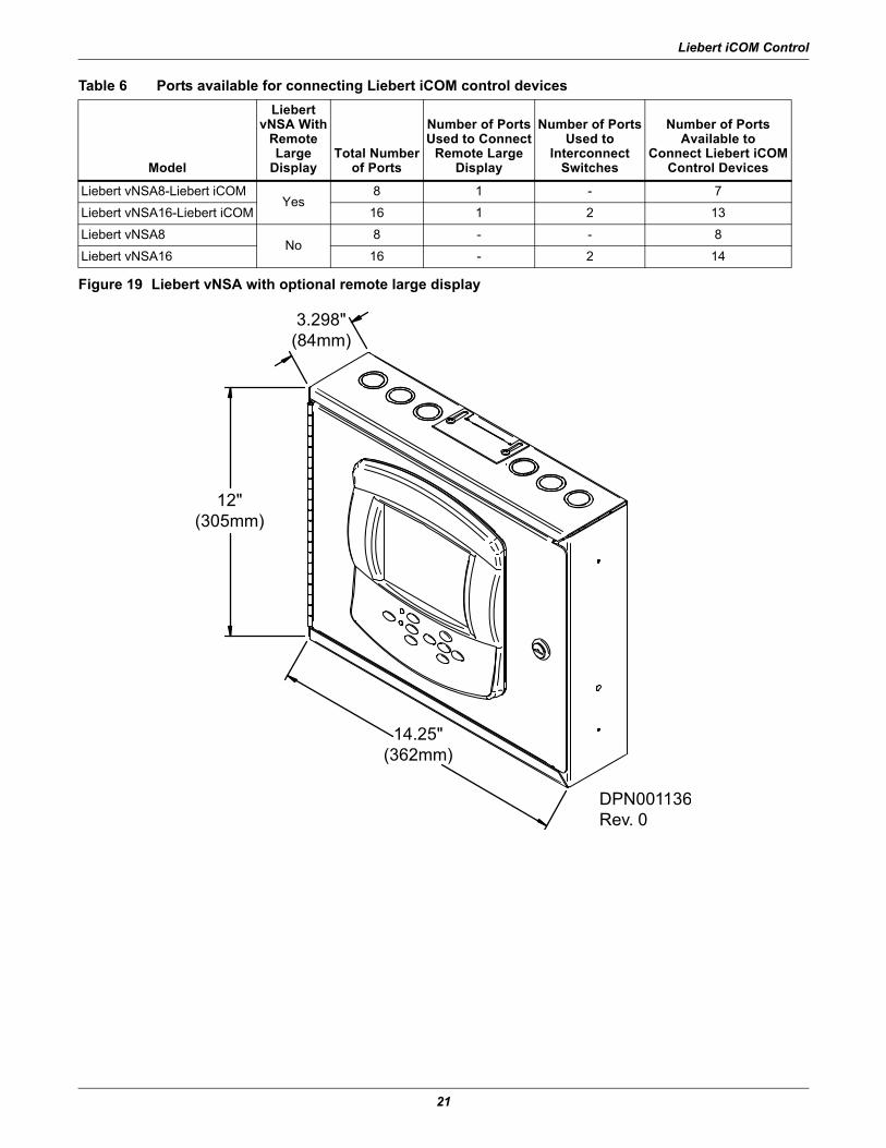
Liebert vNSAThe Liebert vNSA is designed to connect multiple Liebert iCOM control devices. The Liebert vNSA contains either one or two powered industrial rail switches. An optional remote large display can be attached to the front door as well. All models have a power supply that requires connection to a single phase 120V or 240VAC power source. The enclosure features a key lock for security.
The Liebert vNSA supports autonegotiation, autopolarity and autocrossing, allowing for the use of standard network cables for connection to each port, rather than special crossover cables. The switch detects and makes adjustments for the network's speed and transmission mode, polarity and trans-mit-and-receive pins. See the Liebert vNSA user manual, SL-18840, for more details.
The number of ports available for connecting Liebert iCOM control devices varies by model as shown in Table 6. Models with a remote large display attached to the front door utilize one of the available Ethernet ports in the Liebert vNSA. Models with two switches utilize two ports to connect the switches.
Liebert iCOMI/O Board
Straight-ThroughEthernet Cables
CANCable
See Note 4
Large Graphics Display(Rear View)
To / From OtherNetworked Units
U2U Networking Switch(Field-Supplied)
194273
Liebert iCOM Control
21
Figure 19 Liebert vNSA with optional remote large display
Table 6 Ports available for connecting Liebert iCOM control devices
Model
Liebert vNSA With
RemoteLarge
DisplayTotal Number
of Ports
Number of PortsUsed to Connect
Remote LargeDisplay
Number of PortsUsed to
InterconnectSwitches
Number of PortsAvailable to
Connect Liebert iCOMControl Devices
Liebert vNSA8-Liebert iCOMYes
8 1 - 7
Liebert vNSA16-Liebert iCOM 16 1 2 13
Liebert vNSA8No
8 - - 8
Liebert vNSA16 16 - 2 14
3.298"(84mm)
12"(305mm)
14.25"(362mm)
DPN001136Rev. 0
Liebert iCOM Control
22
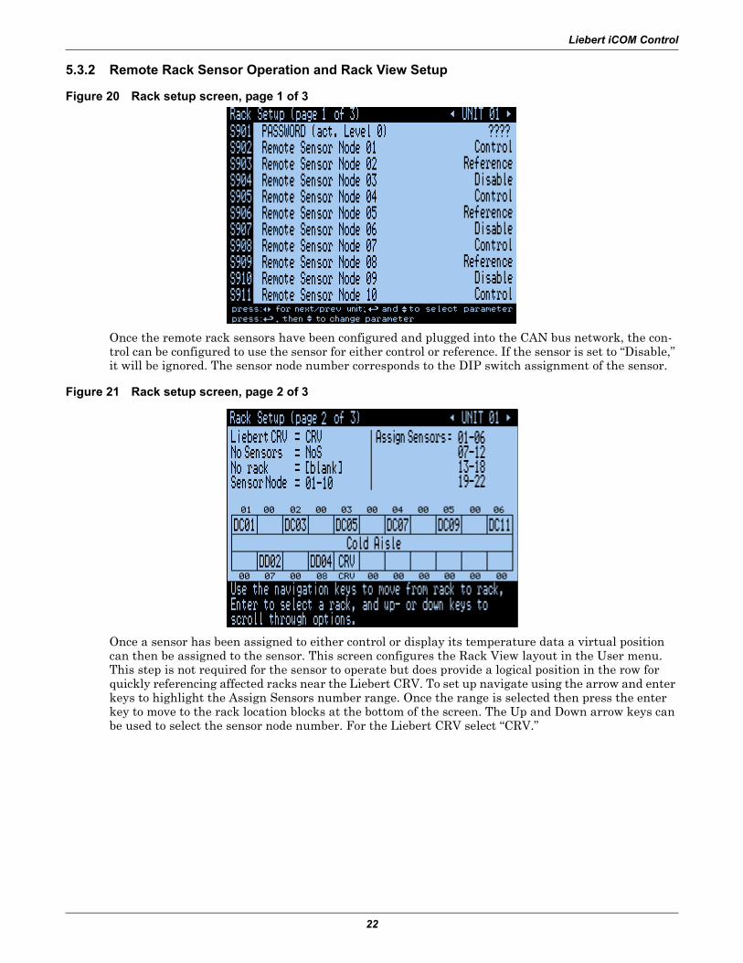
5.3.2 Remote Rack Sensor Operation and Rack View Setup
Figure 20 Rack setup screen, page 1 of 3
Once the remote rack sensors have been configured and plugged into the CAN bus network, the con-trol can be configured to use the sensor for either control or reference. If the sensor is set to “Disable,” it will be ignored. The sensor node number corresponds to the DIP switch assignment of the sensor.
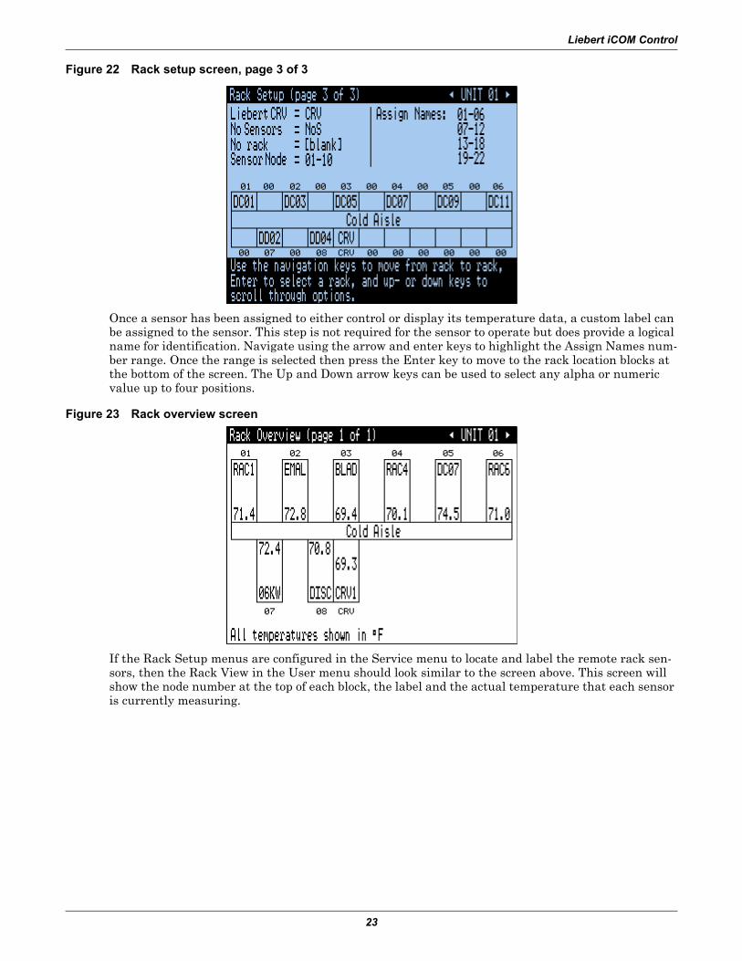
Figure 21 Rack setup screen, page 2 of 3
Once a sensor has been assigned to either control or display its temperature data a virtual position can then be assigned to the sensor. This screen configures the Rack View layout in the User menu. This step is not required for the sensor to operate but does provide a logical position in the row for quickly referencing affected racks near the Liebert CRV. To set up navigate using the arrow and enter keys to highlight the Assign Sensors number range. Once the range is selected then press the enter key to move to the rack location blocks at the bottom of the screen. The Up and Down arrow keys can be used to select the sensor node number. For the Liebert CRV select “CRV.”
Liebert iCOM Control
23
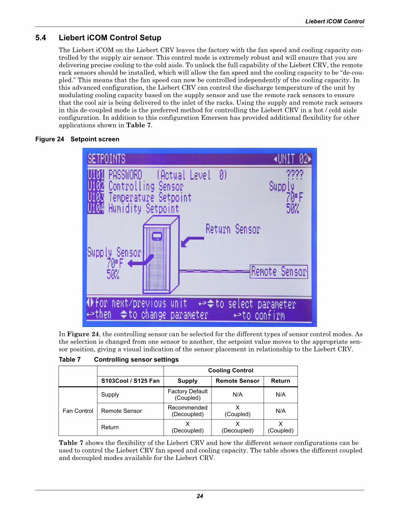
Figure 22 Rack setup screen, page 3 of 3
Once a sensor has been assigned to either control or display its temperature data, a custom label can be assigned to the sensor. This step is not required for the sensor to operate but does provide a logical name for identification. Navigate using the arrow and enter keys to highlight the Assign Names num-ber range. Once the range is selected then press the Enter key to move to the rack location blocks at the bottom of the screen. The Up and Down arrow keys can be used to select any alpha or numeric value up to four positions.
Figure 23 Rack overview screen
If the Rack Setup menus are configured in the Service menu to locate and label the remote rack sen-sors, then the Rack View in the User menu should look similar to the screen above. This screen will show the node number at the top of each block, the label and the actual temperature that each sensor is currently measuring.
Liebert iCOM Control
24
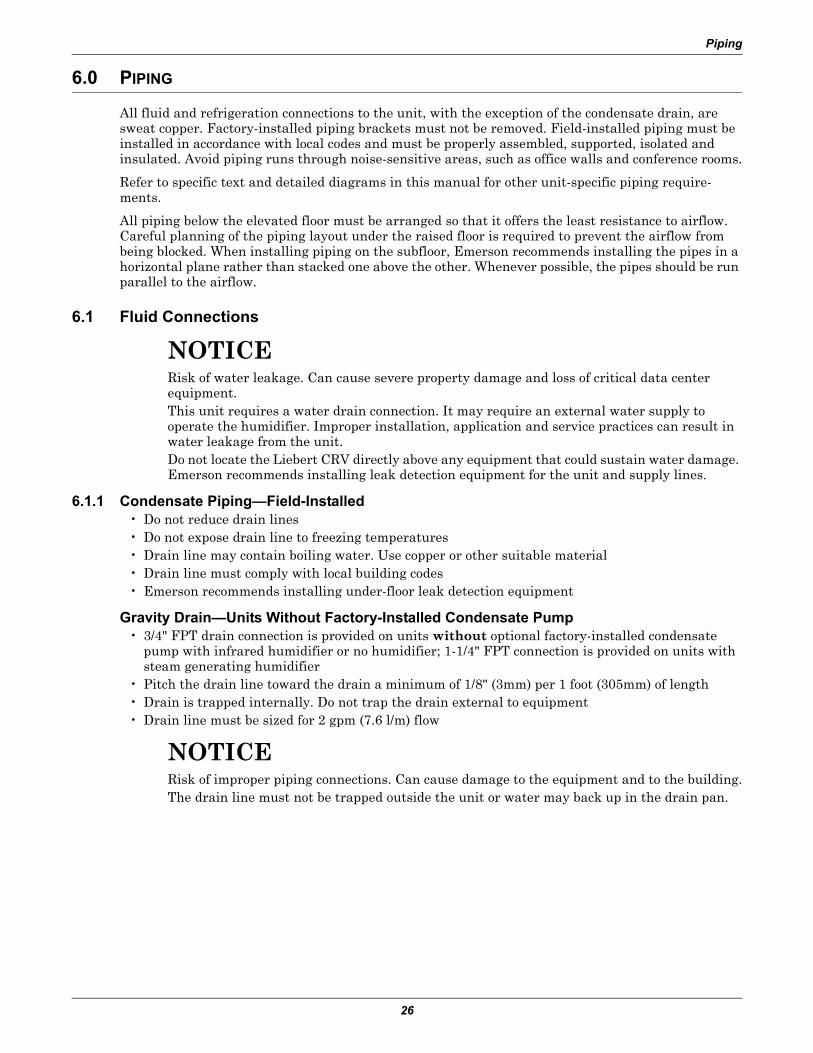
5.4 Liebert iCOM Control SetupThe Liebert iCOM on the Liebert CRV leaves the factory with the fan speed and cooling capacity con-trolled by the supply air sensor. This control mode is extremely robust and will ensure that you are delivering precise cooling to the cold aisle. To unlock the full capability of the Liebert CRV, the remote rack sensors should be installed, which will allow the fan speed and the cooling capacity to be “de-cou-pled.” This means that the fan speed can now be controlled independently of the cooling capacity. In this advanced configuration, the Liebert CRV can control the discharge temperature of the unit by modulating cooling capacity based on the supply sensor and use the remote rack sensors to ensure that the cool air is being delivered to the inlet of the racks. Using the supply and remote rack sensors in this de-coupled mode is the preferred method for controlling the Liebert CRV in a hot / cold aisle configuration. In addition to this configuration Emerson has provided additional flexibility for other applications shown in Table 7.
Figure 24 Setpoint screen
In Figure 24, the controlling sensor can be selected for the different types of sensor control modes. As the selection is changed from one sensor to another, the setpoint value moves to the appropriate sen-sor position, giving a visual indication of the sensor placement in relationship to the Liebert CRV.
Table 7 shows the flexibility of the Liebert CRV and how the different sensor configurations can be used to control the Liebert CRV fan speed and cooling capacity. The table shows the different coupled and decoupled modes available for the Liebert CRV.
Table 7 Controlling sensor settingsCooling Control
S103Cool / S125 Fan Supply Remote Sensor Return
Fan Control
Supply Factory Default(Coupled) N/A N/A
Remote Sensor Recommended(Decoupled)
X(Coupled) N/A
Return X(Decoupled)
X(Decoupled)
X(Coupled)
Liebert iCOM Control
25
5.5 Alarms/EventsThe following alarms and events are supported by the Liebert iCOM control on the Liebert CRV.
Unit On / Off Unit Hours Exceeded Humidifier Low Amps
Standby Mode BMS Disconnected Comp 1 Short Cycle
Power On Room Humidity Problem Humidifier High Amps
Power Off Bottom Fan Failure Humidifier Low Water
Loss of Power Rack Sensor Failure System Off Requested
Unit Disconnected Low Return Humidity System Off Confirmed
High Return Temperature High Return Humidity Fire Alarm
Low temperature Low Supply Temperature Heaters Overheated
High Chill Water Temperature High Supply Temperature Condenser 1 Failure
Loss of Airflow Top Fan Failure Humidifier Cylinder Worn
Loss of Chill Water Flow Reheat Lockout Maintenance Done
Clogged Filters Heat Rej VFD Maintenance Should Be Done!
Low Pressure Transducer Failure Humidifier Lockout Top Fan Failure
Supply Sensor Failure Heat Rej TVSS Control Valve Failure
All fluid and refrigeration connections to the unit, with the exception of the condensate drain, are sweat copper. Factory-installed piping brackets must not be removed. Field-installed piping must be installed in accordance with local codes and must be properly assembled, supported, isolated and insulated. Avoid piping runs through noise-sensitive areas, such as office walls and conference rooms.
Refer to specific text and detailed diagrams in this manual for other unit-specific piping require-ments.
All piping below the elevated floor must be arranged so that it offers the least resistance to airflow. Careful planning of the piping layout under the raised floor is required to prevent the airflow from being blocked. When installing piping on the subfloor, Emerson recommends installing the pipes in a horizontal plane rather than stacked one above the other. Whenever possible, the pipes should be run parallel to the airflow.
6.1 Fluid Connections
NOTICERisk of water leakage. Can cause severe property damage and loss of critical data center equipment.This unit requires a water drain connection. It may require an external water supply to operate the humidifier. Improper installation, application and service practices can result in water leakage from the unit.Do not locate the Liebert CRV directly above any equipment that could sustain water damage. Emerson recommends installing leak detection equipment for the unit and supply lines.
6.1.1 Condensate Piping—Field-Installed• Do not reduce drain lines• Do not expose drain line to freezing temperatures• Drain line may contain boiling water. Use copper or other suitable material• Drain line must comply with local building codes• Emerson recommends installing under-floor leak detection equipment
Gravity Drain—Units Without Factory-Installed Condensate Pump• 3/4" FPT drain connection is provided on units without optional factory-installed condensate
pump with infrared humidifier or no humidifier; 1-1/4" FPT connection is provided on units with steam generating humidifier
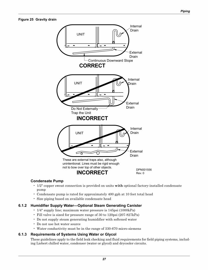
• Pitch the drain line toward the drain a minimum of 1/8" (3mm) per 1 foot (305mm) of length• Drain is trapped internally. Do not trap the drain external to equipment• Drain line must be sized for 2 gpm (7.6 l/m) flow
NOTICERisk of improper piping connections. Can cause damage to the equipment and to the building.The drain line must not be trapped outside the unit or water may back up in the drain pan.
Piping
27
Figure 25 Gravity drain
Condensate Pump• 1/2" copper sweat connection is provided on units with optional factory-installed condensate
pump• Condensate pump is rated for approximately 400 gph at 10 feet total head• Size piping based on available condensate head
6.1.2 Humidifier Supply Water—Optional Steam Generating Canister• 1/4" supply line; maximum water pressure is 145psi (1000kPa)• Fill valve is sized for pressure range of 30 to 120psi (207-827kPa)• Do not supply steam generating humidifier with softened water• Do not use hot water source• Water conductivity must be in the range of 330-670 micro-siemens
6.1.3 Requirements of Systems Using Water or GlycolThese guidelines apply to the field leak checking and fluid requirements for field piping systems, includ-ing Liebert chilled water, condenser (water or glycol) and drycooler circuits.
CORRECT
INCORRECT
UNIT
InternalDrain
ExternalDrain
Continuous Downward Slope
InternalDrainUNIT
UNIT
ExternalDrain
InternalDrain
ExternalDrain
These are external traps also, althoughunintentional. Lines must be rigid enoughnot to bow over top of other objects.
INCORRECT
Do Not ExternallyTrap the Unit
DPN001556Rev. 0
Piping
28
General Guidelines• Equipment damage and personal injury can result from improper piping installation, leak check-
ing, fluid chemistry and fluid maintenance.• Follow local piping codes, safety codes.• Qualified personnel must install and inspect system piping.• Contact a local water consultant regarding water quality, corrosion protection and freeze protec-
tion requirements.• Install manual shutoff valves at the supply and return line to each indoor unit and drycooler to
permit routine service and emergency isolation of the unit.
NOTICERisk of frozen fluids. Can cause equipment damage and building damage.Freezing system fluids can rupture piping. Complete system drain-down cannot be ensured. When the field piping or unit may be exposed to freezing temperatures, charge the system with the proper percentage of glycol and water for the coldest design ambient.Automotive antifreeze is unacceptable and must NOT be used in any glycol fluid system.
NOTICERisk of corrosion. Can cause equipment damage.Read and follow individual unit installation instructions for precautions regarding fluid system design, material selection and use of field-provided devices. Liebert systems contain iron and copper alloys that require appropriate corrosion protection.Contact a local water consultant regarding water quality, corrosion and freeze protection requirements.Water chemistry varies greatly by location, as do the required additives, called inhibitors, that reduce the corrosive effect of the fluids on the piping systems and components. The chemistry of the water used must be considered, because water from some sources may contain corrosive elements that reduce the effectiveness of the inhibited formulation. Preferably, surface waters that are classified as soft and are low in chloride and sulfate ion content should be employed. Proper inhibitor maintenance must be performed in order to prevent corrosion of the system. Consult glycol manufacturer for testing and maintenance of inhibitors.Commercial ethylene glycol (Union Carbide Ucartherm, Dow Chemical Dowtherm SR-1 and Texaco E.G. Heat Transfer Fluid 100), when pure, is generally less corrosive to the common metals of construction than water itself. It will, however, assume the corrosivity of the water from which it is prepared and may become increasingly corrosive with use if not properly inhibited.
NOTICERisk of oxide layer formation. Can cause equipment damage.Idle fluid allows the collection of sediment that prevents the formation of a protective oxide layer on the inside of tubes. Keep unit switched ON and system pump operating.
Leak Checking of Unit and Field PipingLiebert unit fluid systems are factory-checked for leaks and may be shipped with a nitrogen holding charge. Liebert unit fluid circuits should be checked for leaks at installation as described below.
NOTEDuring leak checking of field-installed piping, Emerson recommends that the unit be isolated using field-installed shutoff valves. When the Liebert units are included in a leak test, use of fluid for pressure testing is recommended. When pressurized gas is used for leak testing the Liebert unit, the maximum recommended pressure is 30 psig (2 bars) and tightness of the unit should be verified by pressure decay over time, (<2 psig/hour [0.3 bars/hour]) or sensing a tracer gas with suitable instrumentation. Dry seals in fluid valves and pumps may not hold a high gas pressure.
Refrigerant Connections
29
7.0 REFRIGERANT CONNECTIONS
NOTICERisk of oil contamination with water. Can cause equipment damage.The piping must not be open to the atmosphere for extended periods because the Liebert CRV requires POE (polyol ester) oil. POE oil absorbs water at a much faster rate when exposed to air than previously used oils. Because water is the enemy of a reliable refrigeration system, extreme care must be used when opening systems during installation or service. If water is absorbed into the POE oil, it will not be easily removed and will not be removed through the normal evacuation process. If the oil is too wet, it may require an oil change. POE oils also have a property that makes them act as a solvent in a refrigeration system. Maintaining system cleanliness is extremely important because the oil will tend to bring any foreign matter back to the compressor.
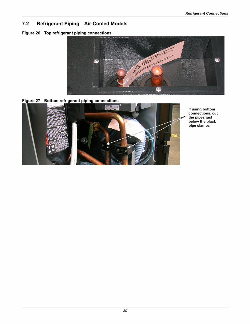
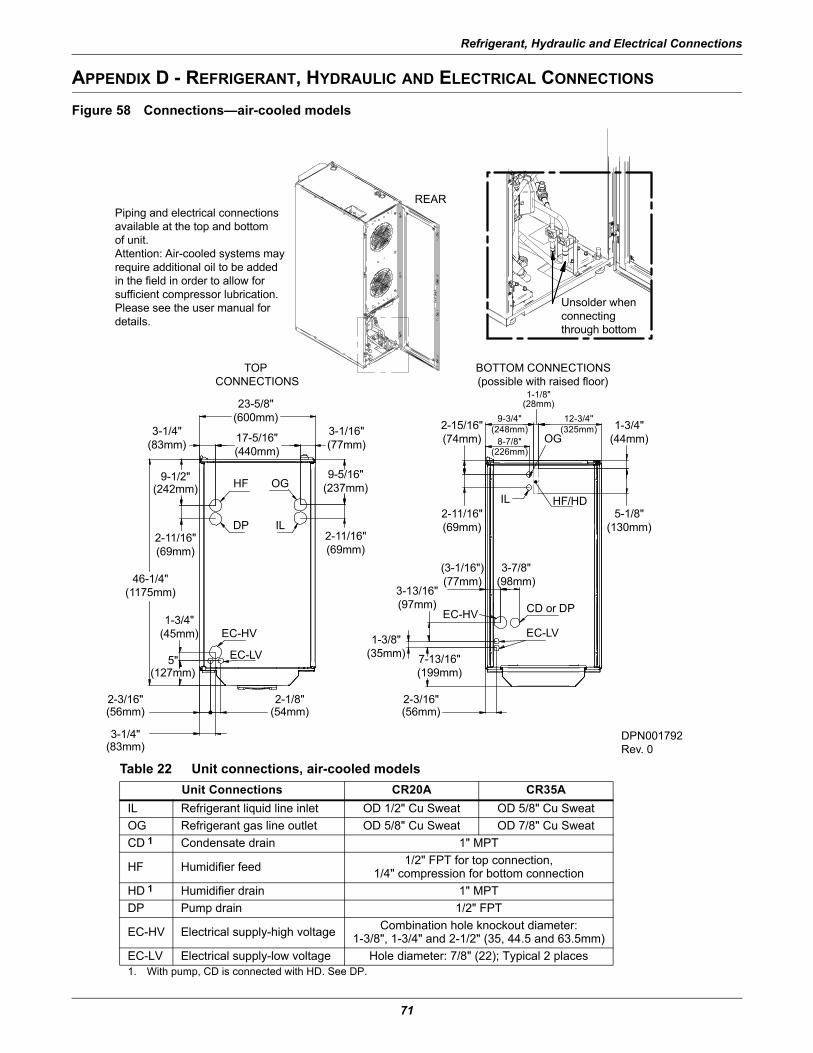
The Liebert CRV can be connected to a condenser through either the top or bottom of the unit. The unit is piped for connections at the top of the unit as shown in Figure 26, with provision for connec-tion through the bottom of the unit.
Connecting through the bottom of the unit requires cutting the liquid and suction lines as shown in Figure 27. Cutting these lines disconnects the top connections from the rest of the refrigeration system.
Air-cooled units are shipped with a holding charge of nitrogen.
7.1 Piping Guidelines—Air-Cooled Units• Indoor unit ships with a nitrogen holding charge; do not vent the evaporator until all refrigerant
piping is in place, ready for connection to the unit and condenser • Use copper piping with high temperature brazed joints • Isolate piping from building using vibration-isolating supports • Refer to Figures 30 and 31 for piping sizes • Refer to condenser installation manual for charging information • Install traps on hot gas (discharge) lines at the base of vertical risers and every 15 feet (4.6m) of
vertical rise.• See Table 9 for the allowable elevation difference between the condenser and the Liebert CRV.• Consult factory if piping run exceeds 150 feet (46m) equivalent length• Keep piping clean and dry, especially on units with R-410A refrigerant• Avoid piping runs through noise-sensitive areas • Do not run piping directly in front of airstream of any air conditioner• Refrigerant oil – do not mix oil types
Refer to ASHRAE Refrigeration Handbook for general, good-practice refrigeration piping.
! WARNINGRisk of explosive discharge from high-pressure refrigerant. Can cause injury or death.This unit contains fluids and/or gases under high pressure.Relieve pressure before working with piping.
! WARNINGRisk of refrigerant system rupture or explosion from over pressurization. Can cause equipment damage, injury or death.If a pressure relief device is not provided with the condenser unit, the system installer must provide and install a discharge pressure relief valve rated for a maximum of 609psig (42bar) in the high side refrigerant circuit. Do not install a shutoff valve between the compressor and the field installed relief valve.One or more additional pressure relief valves are required downstream of all field-installed isolation valves. Do not isolate any refrigerant circuits from overpressurization protection.
Refrigerant Connections
30
7.2 Refrigerant Piping—Air-Cooled Models
Figure 26 Top refrigerant piping connections
Figure 27 Bottom refrigerant piping connections
If using bottom connections, cut the pipes just below the black pipe clamps
Refrigerant Connections
31
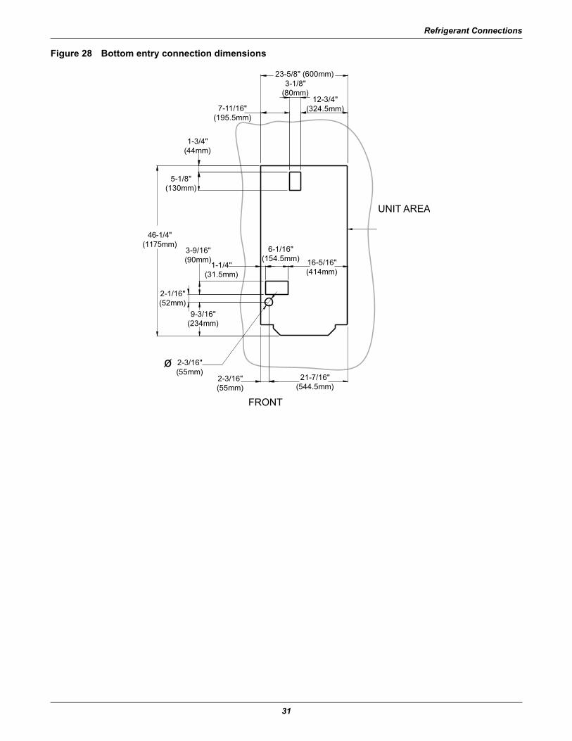
Figure 28 Bottom entry connection dimensions
FRONT
5-1/8"(130mm)
12-3/4"(324.5mm)7-11/16"
(195.5mm)
3-1/8"(80mm)
23-5/8" (600mm)
UNIT AREA
2-3/16"(55mm)
2-3/16"(55mm)
16-5/16"(414mm)
6-1/16"(154.5mm)
1-1/4"(31.5mm)
21-7/16"(544.5mm)
9-3/16"(234mm)
2-1/16"(52mm)
3-9/16"(90mm)
1-3/4"(44mm)
46-1/4"(1175mm)
o
Refrigerant Connections
32
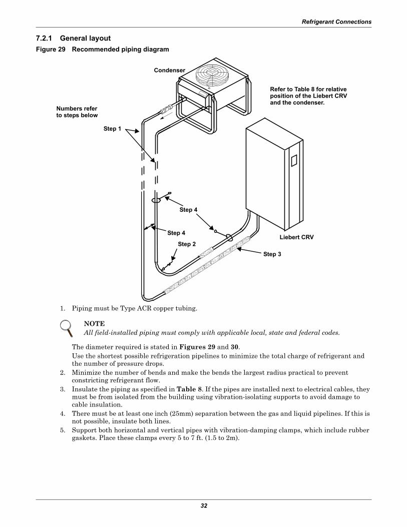
7.2.1 General layoutFigure 29 Recommended piping diagram
1. Piping must be Type ACR copper tubing.
The diameter required is stated in Figures 29 and 30.Use the shortest possible refrigeration pipelines to minimize the total charge of refrigerant and the number of pressure drops.
2. Minimize the number of bends and make the bends the largest radius practical to prevent constricting refrigerant flow.
3. Insulate the piping as specified in Table 8. If the pipes are installed next to electrical cables, they must be from isolated from the building using vibration-isolating supports to avoid damage to cable insulation.
4. There must be at least one inch (25mm) separation between the gas and liquid pipelines. If this is not possible, insulate both lines.
5. Support both horizontal and vertical pipes with vibration-damping clamps, which include rubber gaskets. Place these clamps every 5 to 7 ft. (1.5 to 2m).
NOTEAll field-installed piping must comply with applicable local, state and federal codes.
2
1
3
4
5
Numbers refer to steps below
Condenser
Step 2
Step 1
Step 3
Step 4
Step 4
Liebert CRV
Refer to Table 8 for relative position of the Liebert CRV and the condenser.
Refrigerant Connections
33
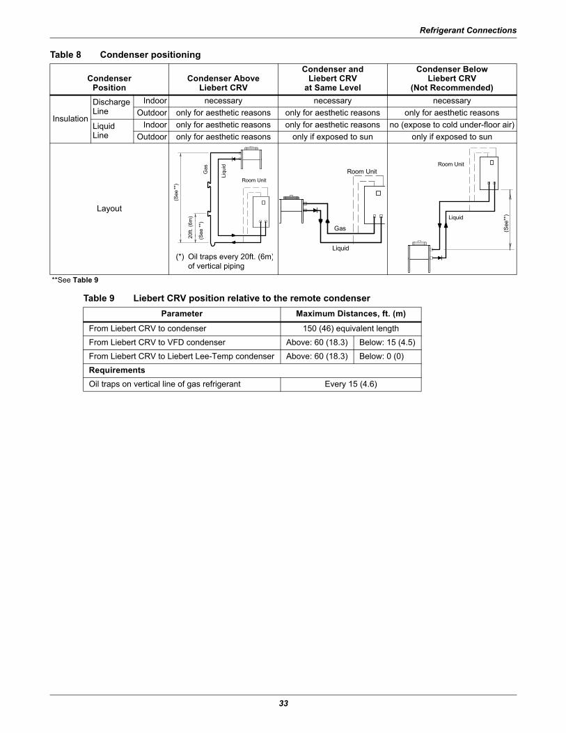
Table 8 Condenser positioning
CondenserPosition
Condenser AboveLiebert CRV
Condenser andLiebert CRV
at Same Level
Condenser BelowLiebert CRV
(Not Recommended)
Insulation
DischargeLine
Indoor necessary necessary necessaryOutdoor only for aesthetic reasons only for aesthetic reasons only for aesthetic reasons
LiquidLine
Indoor only for aesthetic reasons only for aesthetic reasons no (expose to cold under-floor air)Outdoor only for aesthetic reasons only if exposed to sun only if exposed to sun
Layout
**See Table 9
Table 9 Liebert CRV position relative to the remote condenserParameter Maximum Distances, ft. (m)
From Liebert CRV to condenser 150 (46) equivalent length
From Liebert CRV to VFD condenser Above: 60 (18.3) Below: 15 (4.5)
From Liebert CRV to Liebert Lee-Temp condenser Above: 60 (18.3) Below: 0 (0)
RequirementsOil traps on vertical line of gas refrigerant Every 15 (4.6)
20ft.
(6m
)
(See
**)
Gas
Liqu
id
(*) Oil traps every 20ft. (6m)of vertical piping
Room Unit(S
ee**
)
Gas
Liquid
Room Unit
Liquid
Room Unit
(See
**)
Refrigerant Connections
34
7.2.2 Pipe Diameter and Thickness
Figure 30 Piping and refrigerant sizes for Liebert Lee-temp condensers with R-410A
Figure 31 Piping and refrigerant sizes for Liebert air-cooled, VFD control condensers with R-410A
! CAUTIONRisk of explosive discharge. Can cause equipment damage, injury or death.Pipes connecting the Liebert CRV and the condensing unit must meet or exceed the values in Figures 29 and 30.
Refrigerant Connections
35
7.2.3 Installing PipingThe following operations must be carried out by an experienced refrigeration technician.
NOTICERisk of oil contamination with water. Can cause equipment damage.The piping must not be open to the atmosphere for extended periods because the Liebert CRV requires POE (polyol ester) oil. POE oil absorbs water at a much faster rate when exposed to air than previously used oils. Because water is the enemy of a reliable refrigeration system, extreme care must be used when opening systems during installation or service. If water is absorbed into the POE oil, it will not be easily removed and will not be removed through the normal evacuation process. If the oil is too wet, it may require an oil change. POE oils also have a property that makes them act as a solvent in a refrigeration system. Maintaining system cleanliness is extremely important because the oil will tend to bring any foreign matter back to the compressor.
1. When installing the refrigerant piping, note the following:• Brazing:
• All joints must be brazed. • Avoid butt brazes by using couplings or swaging one of the pipes with a swaging tool.• Ensure that all brazed joints are leak-free.• Flow dry nitrogen through the pipes during brazing.
• Always use large-radius curves (bending radius at least equal to pipe diameter). Bend the pipes as follows:
• soft copper: bend by hand or use bending device;• hard copper: use preformed curves.
• To minimize oxidation, avoid overheating the pipes when brazing.2. Connect the pipes to the condenser:
• Condensers with butt-brazed pipe connections: Cut the pipe, enlarge it and braze it to the pipe-line.Respect the direction of refrigerant flow. (See labels on refrigerant.)
3. Wash out the pipelines as follows:a. Plug up the free ends of the pipes.b. Connect a helium or nitrogen cylinder, fitted with a reducer (max. pressure 10 bar), to the 1/4"
SAE Schrader valve of the condenser.c. Pressurize the pipes with helium or nitrogen.d. Unplug the pipes instantaneously.e. Repeat Steps a through d several times.
This operation is especially important when hard copper piping is used.4. Open all the shutoff valves on the room unit.5. Discharge the room unit pressurized with helium (at 1 bar) by opening the charge valves so that
all the branches of the circuit are discharged (e.g., on the receiver, on the low pressure side and on the compressor delivery).
6. Debraze the bottoms from the connections of the room unit.7. Fix (braze) the pipes to the connections on the air conditioner.8. Connect the refrigerant safety valve to the outdoors with a 16 mm (5/8") copper pipe.
Refrigerant Connections
36
7.3 Vacuum and Refrigerant Charge
NOTICERisk of improper refrigerant charge. Can cause equipment damage and reduced efficiency.Check the refrigerant type to be used on the data plate of the air conditioner and on the refrigerating compressor.
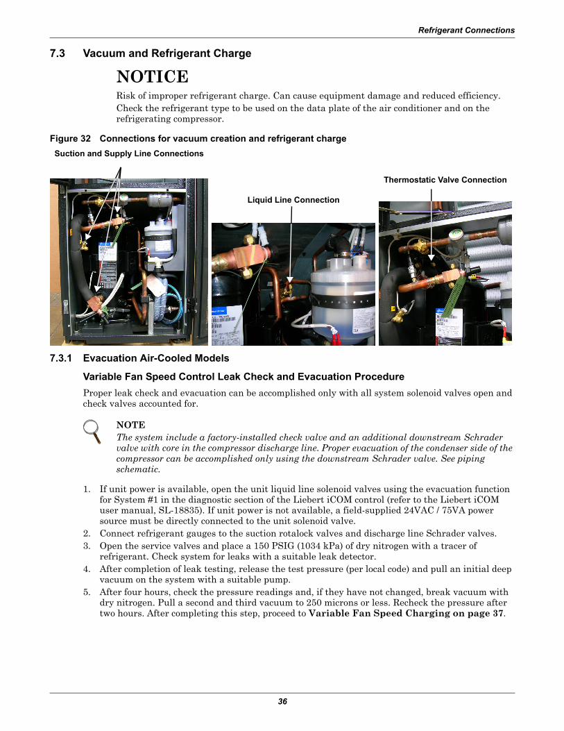
Figure 32 Connections for vacuum creation and refrigerant charge
7.3.1 Evacuation Air-Cooled Models
Variable Fan Speed Control Leak Check and Evacuation ProcedureProper leak check and evacuation can be accomplished only with all system solenoid valves open and check valves accounted for.
1. If unit power is available, open the unit liquid line solenoid valves using the evacuation function for System #1 in the diagnostic section of the Liebert iCOM control (refer to the Liebert iCOM user manual, SL-18835). If unit power is not available, a field-supplied 24VAC / 75VA power source must be directly connected to the unit solenoid valve.
2. Connect refrigerant gauges to the suction rotalock valves and discharge line Schrader valves.3. Open the service valves and place a 150 PSIG (1034 kPa) of dry nitrogen with a tracer of
refrigerant. Check system for leaks with a suitable leak detector.4. After completion of leak testing, release the test pressure (per local code) and pull an initial deep
vacuum on the system with a suitable pump.5. After four hours, check the pressure readings and, if they have not changed, break vacuum with
dry nitrogen. Pull a second and third vacuum to 250 microns or less. Recheck the pressure after two hours. After completing this step, proceed to Variable Fan Speed Charging on page 37.
NOTEThe system include a factory-installed check valve and an additional downstream Schrader valve with core in the compressor discharge line. Proper evacuation of the condenser side of the compressor can be accomplished only using the downstream Schrader valve. See piping schematic.
Suction and Supply Line Connections
Liquid Line Connection
Thermostatic Valve Connection
Refrigerant Connections
37
Variable Fan Speed Charging1. Check unit nameplate for refrigerant type to be used. Unit control configurations differ depending
on refrigerant type.2. Charging the system with refrigerant requires the unit to be in an operational state..3. Calculate the amount of charge for the system. Refer to the unit, condenser and refrigerant line
charge data in Tables 17, 18 and 19.4. Weigh in as much of the system charge as possible before starting the unit.
NOTICERisk of improper refrigerant charging. Can cause equipment damage.Refrigerant R-410A is a blend of two components and must be introduced and charged from the cylinder only as a liquid.When adding liquid refrigerant to an operating system, it may be necessary to add the refrigerant through the compressor suction service valve. Care must be exercised to avoid damage to the compressor. Emerson recommends connecting a sight glass between the charging hose and the compressor suction service valve. This will permit adjustment of the cylinder hand valve so that liquid can leave the cylinder while allowing vapor to enter the compressor.
5. Turn on unit disconnect switch. Operate the unit for 30 minutes using the charging function in the diagnostic section of the Liebert iCOM control (see Liebert iCOM user manual, SL-18835). The charging function operates the compressor at full capacity and energizes the blower motor and the liquid line solenoid valve. The reheat and humidifier are disabled. A minimum 20psig (138kPa) must be established and maintained for the compressor to operate. The charging function can be reset as many times as required to complete unit charging.
6. Charge the unit until the liquid line sight glass becomes clear, then add one additional pound (2.2kg) of refrigerant.
7. As head pressure builds, the variable fan speed controlled condenser fan begins rotating. The fan will run at full speed when sufficient head pressure is developed—fan starts to rotate at 310psig (2137kPa) and is full speed at 400psig (2758kPa).
NOTEA digital scroll compressor will have a clear sight glass only when operating at 100% capacity. When operating below 100%, the sight glass may show bubbles with each 15-second unloading cycle.
Water Connections
38
8.0 WATER CONNECTIONS
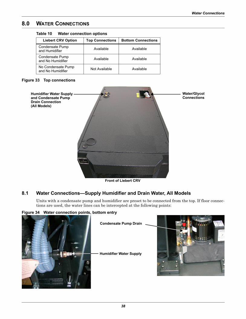
Figure 33 Top connections
8.1 Water Connections—Supply Humidifier and Drain Water, All ModelsUnits with a condensate pump and humidifier are preset to be connected from the top. If floor connec-tions are used, the water lines can be intercepted at the following points:
Figure 34 Water connection points, bottom entry
Table 10 Water connection optionsLiebert CRV Option Top Connections Bottom Connections
Condensate Pumpand Humidifier Available Available
Condensate Pumpand No Humidifier Available Available
No Condensate Pumpand No Humidifier Not Available Available
Humidifier Water Supply and Condensate Pump Drain Connection(All Models)
Water/GlycolConnections
Front of Liebert CRV
Condensate Pump Drain
Humidifier Water Supply
Water Connections
39
• Condensate drain without pump:• Use tubing rated to carry water up to 212°F (100°C) copper, PVC or flexible polythene tubing. • Allow a 2% gradient toward the drain. • Place a drain trap at least 8" (200mm) below the drain tray. The drain trap must be placed
under the unit, in the false floor. • Fill the drain trap with water.
• Humidifier (optional): See Appendix A - - Humidifier.
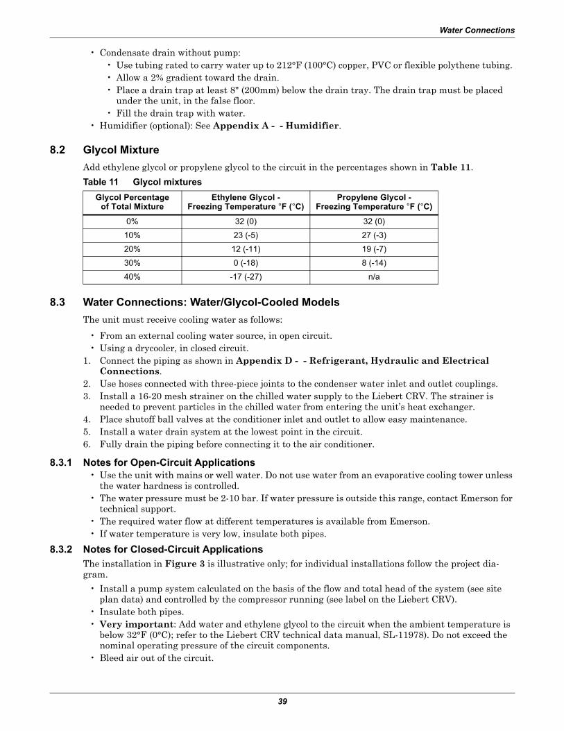
8.2 Glycol MixtureAdd ethylene glycol or propylene glycol to the circuit in the percentages shown in Table 11.
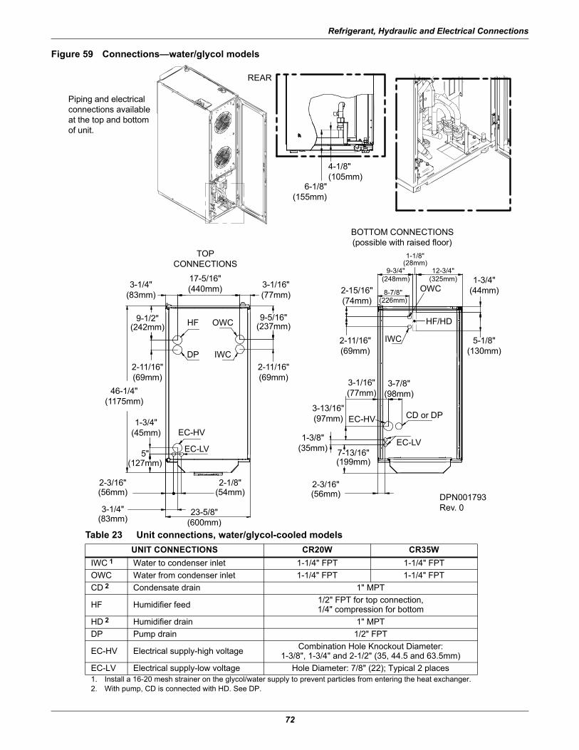
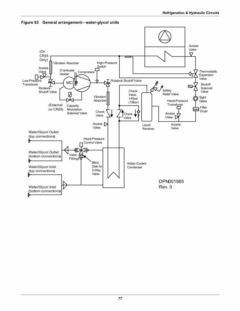
8.3 Water Connections: Water/Glycol-Cooled ModelsThe unit must receive cooling water as follows:
• From an external cooling water source, in open circuit.• Using a drycooler, in closed circuit.
1. Connect the piping as shown in Appendix D - - Refrigerant, Hydraulic and Electrical Connections.
2. Use hoses connected with three-piece joints to the condenser water inlet and outlet couplings. 3. Install a 16-20 mesh strainer on the chilled water supply to the Liebert CRV. The strainer is
needed to prevent particles in the chilled water from entering the unit’s heat exchanger. 4. Place shutoff ball valves at the conditioner inlet and outlet to allow easy maintenance. 5. Install a water drain system at the lowest point in the circuit. 6. Fully drain the piping before connecting it to the air conditioner.
8.3.1 Notes for Open-Circuit Applications• Use the unit with mains or well water. Do not use water from an evaporative cooling tower unless
the water hardness is controlled.• The water pressure must be 2-10 bar. If water pressure is outside this range, contact Emerson for
technical support. • The required water flow at different temperatures is available from Emerson.• If water temperature is very low, insulate both pipes.
8.3.2 Notes for Closed-Circuit ApplicationsThe installation in Figure 3 is illustrative only; for individual installations follow the project dia-gram.
• Install a pump system calculated on the basis of the flow and total head of the system (see site plan data) and controlled by the compressor running (see label on the Liebert CRV).
• Insulate both pipes.• Very important: Add water and ethylene glycol to the circuit when the ambient temperature is
below 32°F (0°C); refer to the Liebert CRV technical data manual, SL-11978). Do not exceed the nominal operating pressure of the circuit components.
• Bleed air out of the circuit.
Table 11 Glycol mixturesGlycol Percentage
of Total MixtureEthylene Glycol -
Freezing Temperature °F (°C)Propylene Glycol -
Freezing Temperature °F (°C)
0% 32 (0) 32 (0)
10% 23 (-5) 27 (-3)
20% 12 (-11) 19 (-7)
30% 0 (-18) 8 (-14)
40% -17 (-27) n/a
Water Connections
40
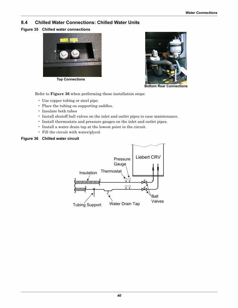
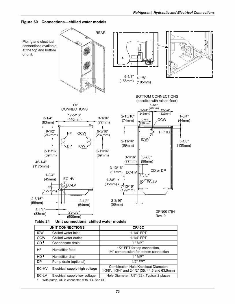
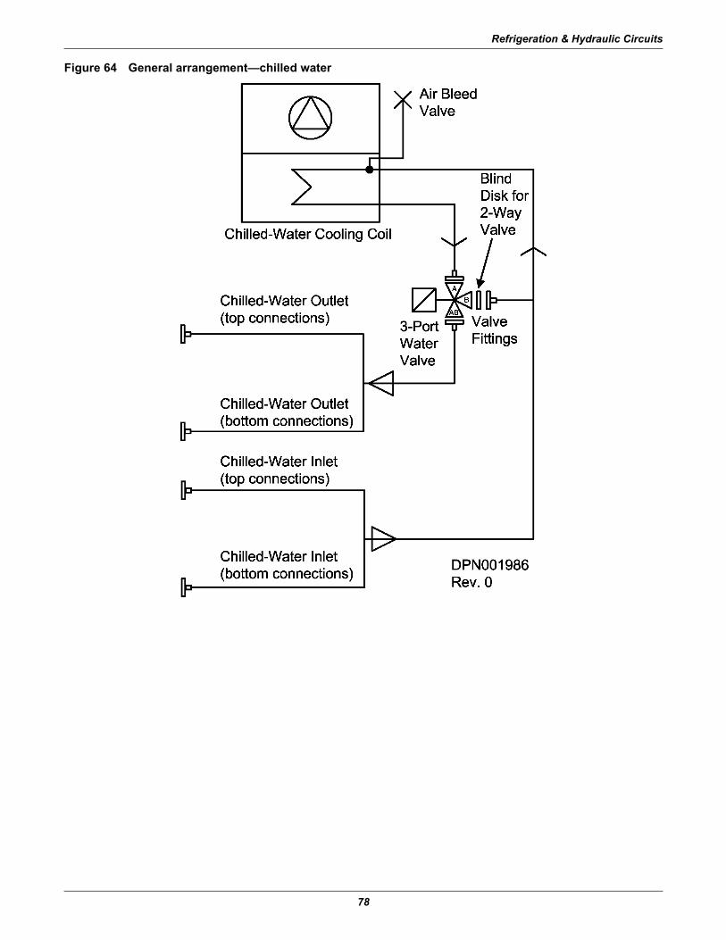
8.4 Chilled Water Connections: Chilled Water UnitsFigure 35 Chilled water connections
Refer to Figure 36 when performing these installation steps:
• Use copper tubing or steel pipe.• Place the tubing on supporting saddles.• Insulate both tubes• Install shutoff ball valves on the inlet and outlet pipes to ease maintenance.• Install thermostats and pressure gauges on the inlet and outlet pipes.• Install a water drain tap at the lowest point in the circuit.• Fill the circuit with water/glycol.
Figure 36 Chilled water circuit
Top Connections
Bottom Rear Connections
Tubing Support Water Drain Tap
BallValves
Thermostat
PressureGauge
Insulation
Liebert CRV
Water Connections
41
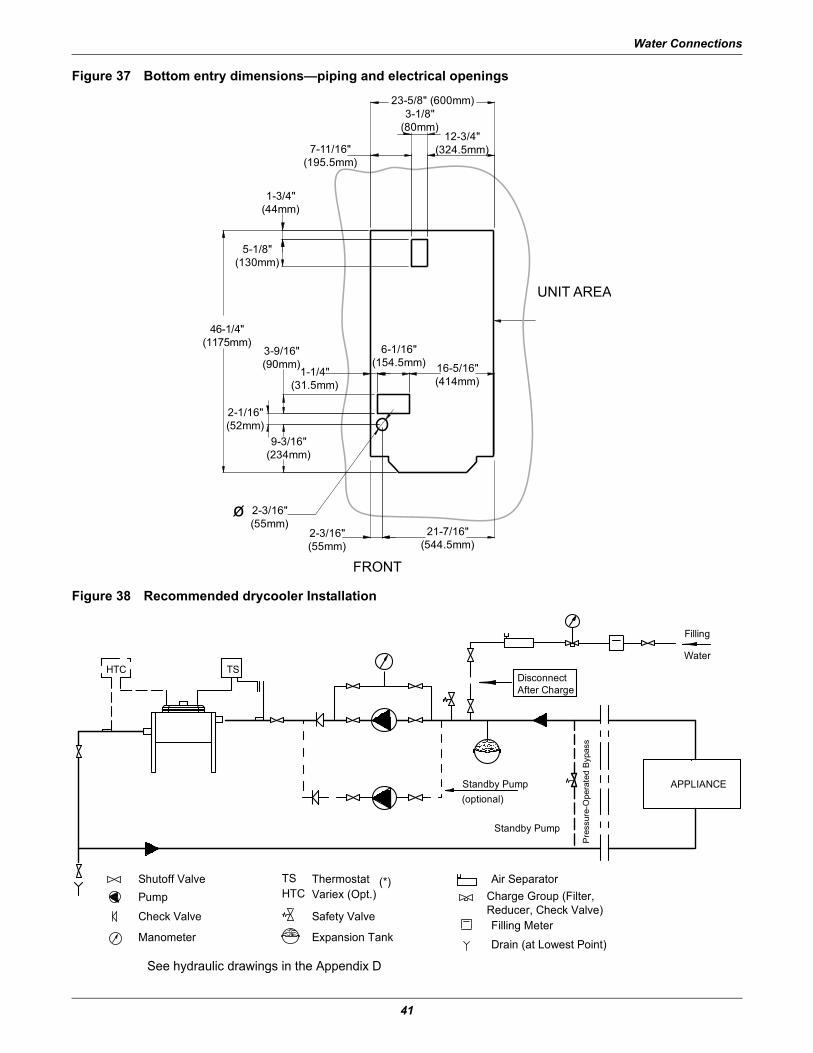
Figure 37 Bottom entry dimensions—piping and electrical openings
Figure 38 Recommended drycooler Installation
FRONT
5-1/8"(130mm)
12-3/4"(324.5mm)7-11/16"
(195.5mm)
3-1/8"(80mm)
23-5/8" (600mm)
UNIT AREA
2-3/16"(55mm)
2-3/16"(55mm)
16-5/16"(414mm)
6-1/16"(154.5mm)
1-1/4"(31.5mm)
21-7/16"(544.5mm)
9-3/16"(234mm)
2-1/16"(52mm)
3-9/16"(90mm)
1-3/4"(44mm)
46-1/4"(1175mm)
o
APPLIANCE
TSHTC
Filling
Water
(optional)
HTCTSShutoff Valve
Pump
Check Valve
Manometer
ThermostatVariex (Opt.)
Safety Valve
Expansion Tank
Air SeparatorCharge Group (Filter,Reducer, Check Valve)Filling MeterDrain (at Lowest Point)
(*)
Standby Pump
Standby Pump
Pre
ssur
e-O
pera
ted
Byp
ass
See hydraulic drawings in the Appendix D
DisconnectAfter Charge
Electrical Connections
42
9.0 ELECTRICAL CONNECTIONS
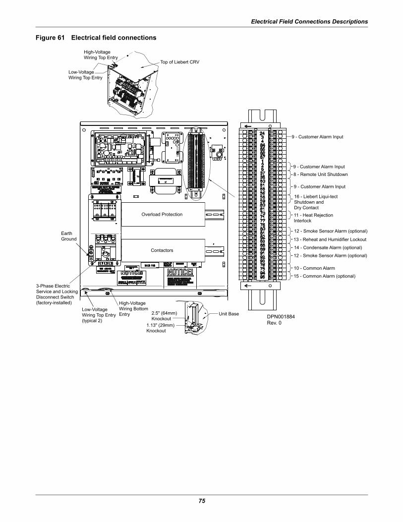
9.1 Electrical connections
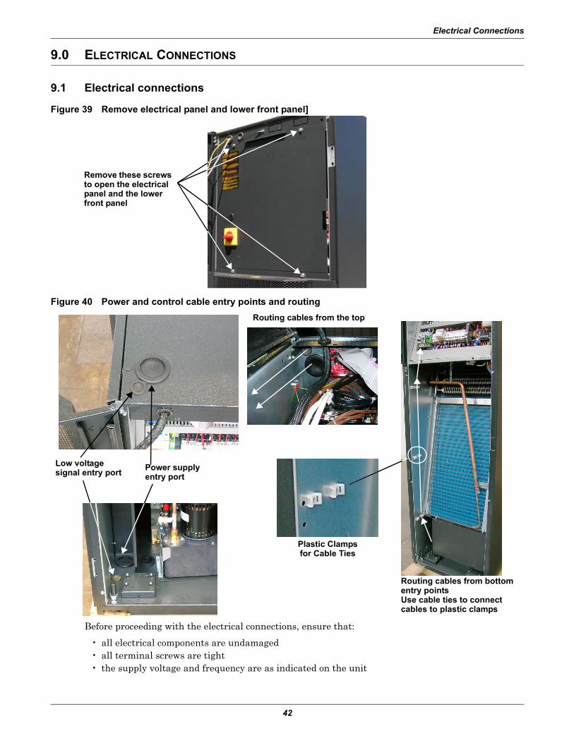
Figure 39 Remove electrical panel and lower front panel]
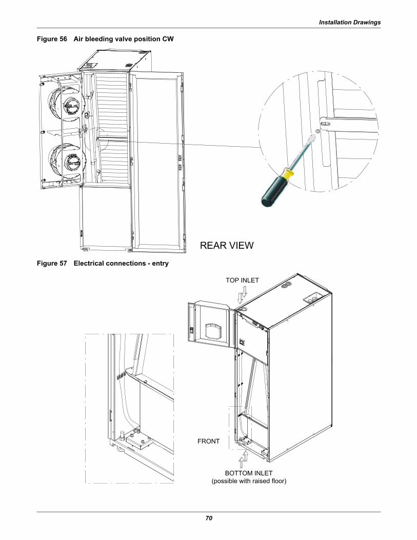
Figure 40 Power and control cable entry points and routing
Before proceeding with the electrical connections, ensure that:
• all electrical components are undamaged• all terminal screws are tight• the supply voltage and frequency are as indicated on the unit
Remove these screws to open the electrical panel and the lower front panel
Low voltagesignal entry port
Routing cables from bottom entry pointsUse cable ties to connect cables to plastic clamps
Power supply entry port
Routing cables from the top
Plastic Clampsfor Cable Ties
Electrical Connections
43
9.1.1 Power Supply Cable Connections• Connect the cable to the line inlet terminal board.• Use the appropriate cable size for the flow, supply voltage and installation type.• Protect the supply using a backup fuse.• Do not fit the supply cable in the raceways inside the machine electric board.• Use only multipolar cables with sheath (CEI20-22).
Wiring Connections• Remote On/Off connections must be provided by the installer.• The General Alarm terminals allow remote alarm signalling.
In case of short circuit, check the affected switch for sticking and replace it if necessary.
See electrical data in Appendix B - Electrical Data.
9.2 Protective Features of the Electrically Commutated FansThe EC fans are protected against:
• Overtemperature of electronics• Overtemperature of motor• Locked rotor protection• Short circuit at the motor output
When any of these failures occurs, the motor stops, electronically, with no potential for separation, and the status relay is released.
The unit does not restart automatic automatically. To reset the alarm, the power supply must be switched Off for 20 minutes once motor is at standstill.
• Input power undervoltage detection:If the utility power falls below 3ph/290VAC (typical value) for 5 seconds or longer, the motor is switched Off, electronically, with no potential for separation, and the status relay is released.When the utility voltage returns to a correct value, the motor restarts automatically.
• Phase failure recognition:If one phase fails for 5 seconds or longer, the motor is switched Off, electronically, with no poten-tial for separation, and the status relay is released.When all three phases return to correct values, the motor restarts automatically in 10 to 40 sec-onds.
The power supply for an external speed-setting potentiometer is protected against short-circuiting.
The motor is overload-protected via motor current limitation.
Electrical Connections
44
9.3 Protective Features of Electrical Heaters
Figure 41 Electrical heating with temperature sensor protection
When the temperature sensor detects overtemperature of electrical heating, the thermal protection turns Off the current. To reset the thermal protection, push the button on the front of the unit (see Figure 41).
9.4 Temperature Probes Placed on RacksThe 2T rack temperature sensors provide feedback to the cooling unit about the condition of the air entering the server racks. This information allows the Liebert CRV to ensure it is providing just enough cold air to each rack, virtually eliminating hot spots. Overcooling and excessive airflow are avoided, greatly reducing unnecessary energy consumption.
Each Liebert CRV includes three 2T rack temperature sensors to monitor three racks. A total of ten 2T temperature sensors can be connected to each cooling unit to monitor every rack a Liebert CRV is protecting. When multiple cooling units are connected in a Unit-to-Unit iCOM control network, all sensor data is shared to optimize their performance as a system.
While 2T rack sensor installation is not required, it is HIGHLY recommended. Each 2T sensor con-sists of two temperature probes for redundancy to be attached to the front door of the server racks. The sensor probes should be located at the highest part of the rack door while still in the supply air-flow path of the servers.
A sensor network can be extended at any time by connecting additional 2T sensors to the last 2T sen-sor on the network. Sensors connect in a daisy chain fashion back to the cooling unit; individual wires from each sensor to the cooling unit are avoided.
2T rack sensors can also be initially installed on empty racks reserved for future growth with the con-trol set to ignore these sensor readings. The extra 2T temperature sensor readings can also be dis-played on the local display and reported remotely for monitoring purposes only; not impacting unit operation. This function provides users with a built-in mini-monitoring system.
2T Sensor Placement GuidelinesThe 2T rack sensors come with the Liebert CRV unit to help prevent any problem spots in the row. Rack sensors help combat cooling problems related to recirculation air, uneven rack loading, and air distribution. The 2T rack sensors are intended for cold aisle use only.
Electrical Connections
45
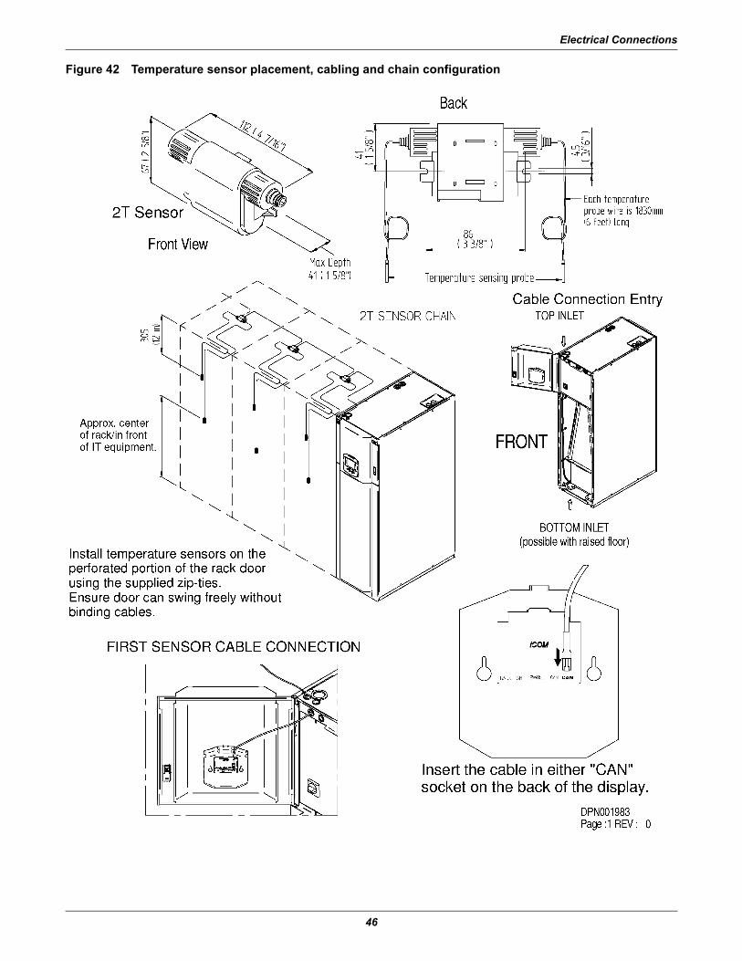
Positioning the 2T Sensor Rack Probes on a RackTo help ensure proper cooling, use the following guidelines to place the Liebert 2T sensor probes:
• on the top of the perforated rack door.• in front of the highest-mounted servers in the rack.• in front of the highest-density area of the rack.• in the airflow path entering the rack.• Do not place the probe directly on the metal surface of the perforated door.
To connect the temperature probes, use only cable with the following characteristics:
• 6 wires, 3 couples, shielded twisted pair • termination: RJ-12 • coupling: according to Liebert iCOM user manual, SL-18835)
Option A:
• 3 x 2 x 0.14 mmq (min), twisted pairs, shielded • plenum rated • 300V • (23/158°F / -5/+70°C)• flexible• characteristic impedance of 108-132 Ohm @50kHz• conductor resistance < 150 Ohm/km• flame-retardant• black jacketing
Option B:
• 24AWG • STP (Shielded Twisted Pair)• CMP (plenum rated)• <15pF capacitance per foot• 300V • 140°F / 60°C • black jacketing • flexibility: must maintain a certain, unspecified flexibility• UL and CSA approved
Electrical Connections
46
Figure 42 Temperature sensor placement, cabling and chain configuration
Startup
47
10.0 STARTUP
10.1 Initial StartupTo start the Liebert CRV:1. Open all valves in the refrigeration circuit according to the instruction label attached to the valve. 2. W Models Only: Open all valves in the water circuit according to the instruction label attached
to the valve. 3. Ensure that the refrigerant charge is correct (see 7.0 - Refrigerant Connections). 4. Using a leak detector, verify that there are no refrigerant leaks. If any leaks are detected, repair
them and recharge as described in 7.0 - Refrigerant Connections. 5. At least 4 hours before startup, close the main switch and the compressor switch on the electrical
panel.
6. Verify that the crankcase heater is working.7. Check to ensure that there are no water leaks.8. If an external condenser or drycooler is installed, start it by supplying power to it.9. Close all MCBs on the electrical panel.10. Check the supply voltage on all phases.11. Check the supply voltage on all phases for the external condenser or drycooler, if fitted.12. Start the unit by pressing the On/Off switch.13. Check the amp draw of all components (see 9.0 - Electrical Connections).14. Check the amp draw of the external condenser/drycooler, if fitted. 15. If the compressor makes a loud, unusual noise, invert the electrical connections of the phases
supplying the corresponding digital scroll compressor, which accepts only one direction of rotation.
16. Ensure that the fans rotate in the correct direction (see arrow on fan).
17. Ensure that all control system settings are correct and that there are no alarms. (See the Liebert iCOM user manual, SL-18835, available at the Liebert Web site, www.liebert.com)
18. W Models Only: Verify the water flow is adequate. 19. W Models Only: For closed circuit units, ensure that the water pump starts when the
compressor starts.
NOTEThe default setting for the Liebert iCOM control is for stand-alone operation. The stand-alone mode allows users to turn on the unit simply by rotating the main switch on the electrical panel. The yellow LED on the Liebert iCOM will light after the unit is turned on because electrical power is present.If the LED does not light: • check the electrical panel power supply• check the protection devices (e.g., thermal switches)• check the fuses.
! WARNINGRisk of contact with rotating devices. Can cause injury or death.The Liebert CRV’s fans will continue spinning after the unit is shut Off. Wait until the fan blades have stopped before working on the unit.
Checks to Perform after StartupOnce the system is operating under load, check the various components, as follows:
1. Verify that the fans are operating properly.2. Ensure that the temperature and relative humidity are being controlled, and that the humidifier
(optional) and heating steps (optional) operate when required.3. Ensure that the compressor operates when required.4. Ensure that the fan operation controller on the external condenser/drycooler (if fitted) is
calibrated correctly, and that it controls the fan operation.5. Record all of the following on the warranty inspection form:
a. All component voltages and current drawsb. All air / water temperatures indoor and outdoorc. All refrigerant and water / glycol pressures,d. All levels of refrigerant and oil in sight glassese. Record refrigerant pressure switch settings and operating pressuresf. Record superheat and sub-cooling.
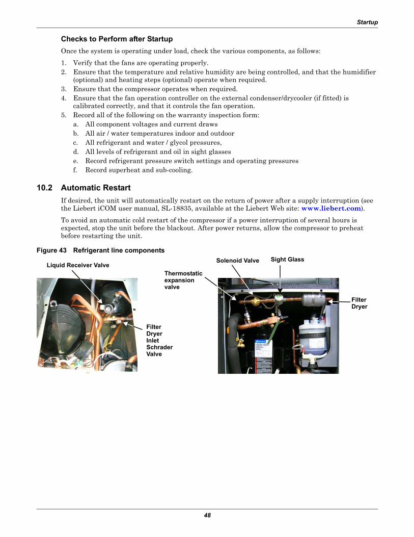
10.2 Automatic RestartIf desired, the unit will automatically restart on the return of power after a supply interruption (see the Liebert iCOM user manual, SL-18835, available at the Liebert Web site: www.liebert.com).
To avoid an automatic cold restart of the compressor if a power interruption of several hours is expected, stop the unit before the blackout. After power returns, allow the compressor to preheat before restarting the unit.
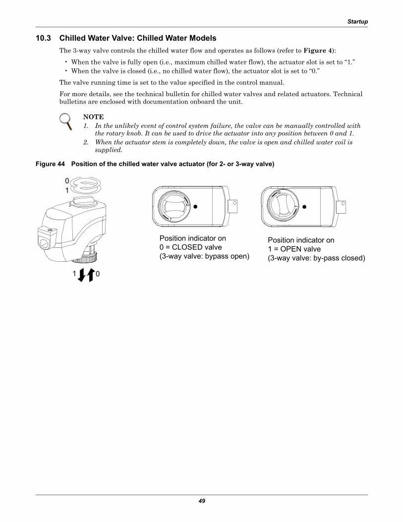
10.3 Chilled Water Valve: Chilled Water ModelsThe 3-way valve controls the chilled water flow and operates as follows (refer to Figure 4):
• When the valve is fully open (i.e., maximum chilled water flow), the actuator slot is set to “1.”• When the valve is closed (i.e., no chilled water flow), the actuator slot is set to “0.”
The valve running time is set to the value specified in the control manual.
For more details, see the technical bulletin for chilled water valves and related actuators. Technical bulletins are enclosed with documentation onboard the unit.
Figure 44 Position of the chilled water valve actuator (for 2- or 3-way valve)
NOTE1. In the unlikely event of control system failure, the valve can be manually controlled with
the rotary knob. It can be used to drive the actuator into any position between 0 and 1.2. When the actuator stem is completely down, the valve is open and chilled water coil is
supplied.
01
01
Position indicator on0 = CLOSED valve(3-way valve: bypass open)
Position indicator on1 = OPEN valve(3-way valve: by-pass closed)
Operation
50
11.0 OPERATION
Unit operation is completely automatic. The unit operates in the following sequence:
• Air is drawn into the unit by the fans, which operate continuously.• The temperature and humidity sensor measures the inlet air, and relays this information to the
control system.• The air is immediately filtered.• The air is then conditioned and expelled from the unit.
Figure 45 Sensor location
The control system compares the relayed information with the programmed setpoint and proportional band values and performs one of the following operations:
• Cooling—Direct expansion mode (DX): The compressor is started and the cold refrigerant flows through the evaporator, thus cooling the air passing through it. For compressor operation see Lie-bert iCOM user manual, SL-18835.
• Chilled water mode (CW)—The three-way valve is opened and the chilled water flows through the coil, thus cooling the air passing through it. For valve operation, see the Liebert iCOM user manual, SL-18835.
• Reheating—Electrical heating (optional): The heating elements heat the air passing over them during dehumidifcation.
• Dehumidification (DX mode)— The temperature of the cooling coil is reduced to remove mois-ture from the air. (Refer also to the Liebert iCOM user manual, SL-18835).
In dehumidification mode, the air after passing over the coil is reheated (if needed) by electrical heaters to stabilize the initial temperature.
• Humidification (optional)—The humidifier creates steam, which is distributed into the air stream via the steam distribution pipe. (See also Appendix A - - Humidifier).
NOTEIf, during dehumidification, the ambient temperature drops below a specified level, dehumidification will stop if necessary. (See the Dehumidification Low Limit section of the Liebert iCOM user manual, SL-18835).
Calibration and Regulation after Startup
51
12.0 CALIBRATION AND REGULATION AFTER STARTUP
The Liebert CRV has been factory-tested and calibrated, but it is very important to check, at startup, the superheating of the thermostatic valve (A/W versions).
• For calibrations of instruments installed on the external condensers/drycoolers, refer to the man-ual for the equipment.
• For control system calibrations, refer to the Liebert iCOM manual, SL-18835. (To prevent erratic operation, do not use temperature and relative humidity setpoints/proportional bands that differ excessively from the default settings.)
12.1 Thermostatic Expansion ValveThe Thermostatic Expansion Valve (TEV) performs one function: It keeps the evaporator supplied with enough refrigerant to satisfy load conditions. It does not effect compressor operation.
Proper valve operation can be determined by measuring superheat. The correct superheat setting is between 10 and 20°F (-12 and -6°C). If too little refrigerant is being fed to the evaporator, the super-heat will be high; if too much refrigerant is being supplied, the superheat will be low.
1. Measure the temperature of the suction line at the point the TEV bulb is clamped.2. Obtain the gauge pressure at the compressor suction valve.3. Add the estimated pressure drop between the bulb’s location and the suction valve.4. Convert the sum of the two pressures to the equivalent temperature.5. Subtract this temperature from the actual suction line temperature. The difference is superheat.
12.1.2 Adjust Superheat Setting with the TEVTo adjust the superheat setting:
1. Remove the valve cap at the bottom of the valve.2. Turn the adjusting stem counterclockwise to lower the superheat.3. Turn the adjusting stem clockwise to increase the superheat.
12.2 Environmental ProtectionMisuse or incorrect calibration of the unit leads to increased energy consumption, resulting in eco-nomic and environmental damage.
NOTEMake no more than one turn of the stem at a time. As long as thirty minutes may be required for the new balance to take place.
Maintenance
52
13.0 MAINTENANCE
13.1 Safety InstructionsAll maintenance operations must strictly observe national, state and local accident prevention regula-tions, especially the regulations concerning electrical systems, refrigerators and manufacturing resources.
Air conditioning equipment maintenance may be performed only by authorized properly trained and qualified personnel.
To keep all warranties valid, the maintenance must adhere to the manufacturer’s regulations.
NOTICERisk of improper maintenance. Can cause equipment damage.All maintenance must be performed only by authorized properly trained and qualified personnel.
Ignoring safety instructions can be dangerous to persons as well as to the environment. Soiled parts always cause a loss of performance and, for switch or control devices, can lead to the breakdown of a plant.
13.2 Spare PartsOnly original spare parts made by Emerson Network Power may be used. Using third-party material can invalidate the warranty. When making seeking technical assistance, always refer to the compo-nent list supplied with the equipment, and specify the model number, serial number and, if available, the part number.
13.3 Maintenance ScheduleConduct monthly, quarterly, biannual and annual checks according to the following guidelines.
All tasks and time periods listed here are the manufacturers’ regulations and must be documented in an inspection report.
! WARNINGRisk of contact with rotating parts and hot surfaces. Can cause equipment damage, injury and death.Perform maintenance only when the system is fully stopped.• Turn Off the system by switching it Off at the controller and the main switch.• Post a warning sign saying “Do not switch on.”• Electrical components of the unit must be switched Off and checked to ensure they are not
receiving electrical input power.
NOTE1. When replacing a faulty component, follow the relevant manufacturer instructions.2. When the spare parts must be brazed, be careful not to damage the internal parts (gaskets,
seals, O-rings, etc.).
Maintenance
53
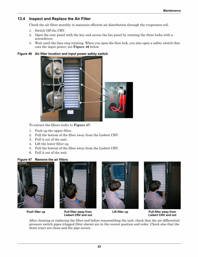
13.4 Inspect and Replace the Air FilterCheck the air filter monthly to maintain efficient air distribution through the evaporator coil.
1. Switch Off the CRV.2. Open the rear panel with the key and access the fan panel by rotating the three locks with a
screwdriver.3. Wait until the fans stop rotating. When you open the first lock, you also open a safety switch that
cuts the input power; see Figure 46 below.
Figure 46 Air filter location and input power safety switch
To extract the filters (refer to Figure 47:
1. Push up the upper filter.2. Pull the bottom of the filter away from the Liebert CRV.3. Pull it out of the unit.4. Lift the lower filter up5. Pull the bottom of the filter away from the Liebert CRV.6. Pull it out of the unit.
Figure 47 Remove the air filters
After cleaning or replacing the filter and before reassembling the unit, check that the air differential pressure switch pipes (clogged filter alarm) are in the correct position and order. Check also that the drain trays are clean and the pipe secure.
Push filter up Pull filter away from Liebert CRV and out
Lift filter up Pull filter away from Liebert CRV and out
Maintenance
54
Figure 48 Differential pressure switch tubes
Before restarting the unit, be sure that the microswitches are properly closed; otherwise, the unit remains in safety status.
13.5 Condensate Drain and Condensate Pump Systems
13.5.1 Condensate drain Check for and clear obstructions in tubing during routine maintenance.
13.5.2 Condensate Pump, Dual-Float
Figure 49 Condensate pump
1. Disconnect power to the unit using the disconnect switch.2. Check for and clear obstructions in gravity lines leading to the condensate pump.3. Remove the sump, clean with a stiff nylon brush and flush with water.4. Inspect and clear clogs in the discharge check valve and float mechanism.5. Reassemble and check for leaks.
13.6 Air-Cooled Condenser and Drycoolers1. Clear the coil surface of all debris that might inhibit airflow. 2. Check for and correct bent or damaged coil fins. 3. Do not permit snow to accumulate around or under an outdoor unit.4. Consider having the coil surface commercially cleaned periodically.5. Inspect fans, motors and controls for proper operation. 6. Check all piping and capillaries for proper support. 7. Inspect for leaks.
Differential pressure
switch tubes
Maintenance
55
13.7 Electrical Heaters1. Inspect and clean reheat elements.2. Inspect and tighten support hardware.
Table 12 Maintenance schedule
Component
Maintenance Period
Monthly By User
Every3 Months
Every6 Months Annually
General
Check unit display for clogged-filter warning XCheck for irregular noise from unit fans XCheck for irregular noise from compressor (if applicable) X
Check for irregular noise from remotecondenser fan(s) (if applicable) X
FiltersCheck state of filters XReplace air filter if necessary XCheck filter switch functionality X
Blowers
Verify impellers move freely XCheck bearings XCheck motor mounts for tightness XCheck fan safety switch X
Electrical/Electronics
Check condition of contacts XCheck electrical connections XCheck operation of controller XCheck unit operation sequence X
Steam-Generating Humidifier
Check cylinder and pan XCheck condition of steam hoses XVerify filling solenoid valve is operating properly X
Cooling Water Circuit(Water/Glycol and
Chilled Water Units)
Check circuit for leakage/general condition XCheck water (glycol) inlet temperature XCheck water regulating valve operation XCheck in/out water (glycol) Δt XCheck mixture glycol level (if applicable) X
Refrigerating Circuit
Check compressor noise/vibrations XCheck oil level through compressor sight glass XAdjust/tighten compressor/functional elements XCheck sight glass for problem detection XCheck starting/running amps XCheck refrigerating circuit main pressures XCheck compressor suction superheat XCheck discharge temperature XCheck subcooling X
Air-CooledCondenser/Drycooler
(if applicable)
Check fan bearings XCheck fan motor mounts for tightness XCheck coil condition XCheck pipeline supports XCheck fan speed controller operation X
Water/Glycol Pump See manual for the pump
Maintenance
56
13.8 Dismantling the UnitThe Liebert CRV has been designed and built to ensure continuous operation.
The working life of some of the main components, such as the fan and the compressor, depends on proper maintenance.
NOTICERisk of release of hazardous substances into the environment. Can cause environmental pollution and violation of environmental regulations.The Liebert CRV contains substances and components hazardous for the environment (electronic components, refrigerating gases and oils). At the end of its useful life, the Liebert CRV must be dismantled by specialized refrigerating technicians. The unit must be delivered to suitable centers specializing in the collection and disposal of equipment containing hazardous substances.
The refrigerating fluid and the lubricating oil inside the circuit must be recovered according to the laws in the relevant country.
To recover the gas, use all the connections described in 7.0 - Refrigerant Connections.
13.9 F-Gas Regulation (EC) No. 842/2006Stationary air conditioning placed in the European Community market and operating with fluori-nated greenhouse gases (F-gas), such as R-134A, R-407C and R-410A, must comply with the F-gas Regulation (applied since July 4, 2007).
Following considerations must be observed when operating with the above-mentioned equipment:
• Fluorinated greenhouse gases are covered by the Kyoto Protocol. • The fluorinated greenhouse gases in this equipment should not be vented to the atmosphere. • Referring to the value noted in Annex I of Regulation (EC) No 842/2006, the following list speci-
fies the global warming potential (GWP) of some major F-gases:• R-134A: GWP 1300• R-407C: GWP 1610• R-410A: GWP 1890
• Operators of the above-mentioned applications, which contain fluorinated greenhouse gases, shall, using all measures that are technically feasible and do not entail disproportionate cost:a. prevent leakage of these gases and, as soon as possible, repair any detected leakage; b. ensure that they are checked for leakage by certified personnel; c. ensure arrangements are put in place for the proper recovery by certified personnel. d. In case of applications containing 3 kg (6 kg in case of hermetically sealed systems) or more of
F-gases, certified personnel and companies (according to Reg. 303/2008) provide regular leak testing (according to Reg. 1516/2007 and Reg. 1497/2007) and maintain records of maintenance activities in a dedicated log book.
e. Recovery for the purpose of recycling, reclamation or destruction of the fluorinated greenhouse gases, pursuant to Art. 4 (Recovery) of Reg.842/2006, shall take place before the final disposal of that equipment and, when appropriate, during its servicing and maintenance.
• Operator, according to Reg. 842/2006, Article 2, point 6, means the natural or legal person exercis-ing actual power over the technical functioning of the equipment and system covered by the Regu-lation. The State may, in defined, specific situations, designate the owner as being responsible for the operator's obligations.
• Direct methods of leakage checking approved by the manufacturer (Reg. 1516/2007 and Reg. 1497/2007):a. gas detection device adapted to the refrigerant in the system; the sensitivity of portable gas
detection devices (as a direct test method) shall be at least five grams per year.b. proprietary bubble solutions / soapsuds.
Maintenance
57
• Additional information located in a dedicated label of the unit (Reg. 1494/2007):a. Where fluorinated greenhouse gas is foreseen to be added to the equipment outside of the
manufacturing site at the point of installation, a dedicated label accommodates notation of both the quantity (kg) pre-charged in the manufacturing plant and the quantity charged at the installation site, as well as the resulting total quantity of F-gas as a combination of the above-mentioned quantities, in a manner that conforms to legibility and indelibility.Our split units are usually not pre-charged at the factory; in this case, the total quantity of refrigerant charged in the unit must be written in the relevant label, during the commission-ing operation at the installation site.
b. Our packaged units (not split) operating with F-gas are usually fully charged at the factory, and the total amount of refrigerant charge is already reported on the label. In this case, the label has no need of further written information.
c. In general, the above-mentioned information has been located in the main nameplate of the relevant unit.
d. For equipment with double refrigeration circuits, in regards to different requirements based on the quantity of F-gas contained, the required information about refrigerant charge quantities must be listed separately for each individual circuit.
e. For equipment with separate indoor and outdoor sections connected by refrigerant piping, the label information will be on that part of the equipment that is initially charged with the refrigerant. In case of a split system (separate indoor and outdoor sections) without a factory precharge of refrigerant, the mandatory label information will be on that part of the product or equipment that contains the most suitable service points for charging or recovering the fluorinated greenhouse gas(es).
• Safety data sheets of F-gases used into the products are available on demand.
Troubleshooting
58
14.0 TROUBLESHOOTING
Table 13 Unit diagnosticsProblem Possible Cause Corrective Action
Verify that remote temperature sensors are correctly positioned
Remote temperature sensor(s) issue Contact Emerson
Condensation pressure is too high
Air-cooled units: Verify that remote condenser fan(s) are runningWater/glycol units: Check cooling water supplyWater/glycol units: Check cooling water tempCall Emerson Network Power
Chilled water units: inlet water temperature is too high Check cooling water temperature
Refrigerating circuit charge issue Contact your local Emerson representative
Cold air short-cycling issuesVerify unit positioning/room configurationVerify unit air baffles set-upVerify cold aisle containment seals (if applicable)
Insufficient room-cooling capacity Reduce rack heat load or add cooling units (C unit) water-regulating valve issue Contact your local Emerson representativeUnit safety devices intervention Contact your local Emerson representative
Unit fan failsto start Fan is faulty Contact your local Emerson representative
Water dropscarried by airflow
Room humidity is over acceptable limit Check room condition Condensate pan drain is clogged Contact your local Emerson representativeProblem with humidifier control Contact your local Emerson representative
Water on the flooraround the unit
Unit is not properly levelled Adjust the levelling feetUnit condensate drain pipe is clogged Remove pipe obstructionChilled water and water/glycol units: leak in the water circuit Locate and repair the leak
Piping insulation broken/damaged Restore insulation integrityLeak in the draining circuit Contact your local Emerson representativeCondensate pump is faulty Contact your local Emerson representativeLeak in the humidifier filling hose Contact your local Emerson representative
Cooling unit noise levelis higherthan expected
Incorrect positioning of remotetemperature sensor(s) Verify correct positioning of temperature sensors
Unbalanced heat load distribution Redistribute rack heat loadRemote temperature sensor(s) issue Contact your local Emerson representative
Unsteadyair deliverytemperature
Faulty temperature sensor(s) Contact your local Emerson representative
Unit controller issue Contact your local Emerson representative
Local display isnot operationalbut unit operates
Local display cable disconnected Connect cableLocal display cable damaged Replace cableLocal display configuration lost Contact your local Emerson representative
Local display isnot operational and unit does notoperate
Unit electrical supply is Off Restore electrical supplyUnit main switch is Off Switch On the unitControl board supply issue Contact your local Emerson representativeControl board issue Contact your local Emerson representative
Humidifier
59
APPENDIX A - HUMIDIFIER
A.1 PRINCIPAL OF OPERATION
When the Liebert iCOM calls, the cylinder fills to 100% of the Full Load Amperage (FLA) or to the top of the cylinder, whichever comes first. See Figure 50. If it reaches 100% FLA, the water heats and boils away to a level giving 80% FLA. An electronic timer uses the rate of amp fall to determine the water level. The objective is to concentrate current carrying minerals in the cylinder so that a smaller volume of water is required to produce the rated steam output. This extends the life of the disposable cylinder by minimizing electrode coverage and reducing energy use because the high concentration allows a minimal drain rate. When 80% FLA is reached, the fill valve will open, refilling the cylinder to 100% FLA. On occasion, the drain valve will also come on if the water level is too low, indicating too high a concentration and the need to dilute the water in the cylinder. If the water reaches the top of the cylinder before 100% FLA, the fill valve shuts Off via the sensor, and the fill-boil-fill-boil cycle continues, cycling Off the red high water sensor light until the concentration becomes high enough to reach 100% FLA. The above-described control process will then take over.
Figure 50 General diagram—humidifier operation
A.1.1 Humidifier Water Supply and PlumbingThe fill valve is sized for an extended water pressure range of 30 to 80 psi.
For installations where water pressure is less than 15 psi, add a pressure boost pump and notify the factory; a fill valve with an oversized opening will be supplied.
For installations where water pressure is greater than 80 psi, install a pressure reducing valve in the water feed line to the unit.
With dirty or muddy water sources (e.g., some well sources), ensure proper filtration by adding an external filter to the water line entering the unit. (Consult factory for accessories such as filters.)
Humidifier
60
NOTICERisk of improper water supply. Can reduce humidifier efficiency or obstruct humidifier plumbing.Do not use completely demineralized water with this unit; it is the minerals that allow the electrode principle to work.Do not use a hot water source; it will cause deposits that will eventually block the fill valve opening.
A.1.2 Humidifier Water ConnectionA copper compression olive type coupling for 1/4" O.D. soft copper tubing is provided with the unit and requires no soldering for the water connection to the unit.
An isolating valve should ALWAYS be placed in the feed water line to allow service of the fill valve.
Each unit is fitted with a fill solenoid valve located on the base drain pan.
Flow openings are designed for water pressure from 30 to 80 psi and are protected by the built-in strainer.
For inlet water pressure outside this range, the factory should be contacted.
Figure 51 Water connection to humidifier
7/8" DrainConnection
Use 7/8" ID Hose from Factory
3/8" Cold WaterOlive Connection
Humidifier
61
A.1.3 Humidifier Startup and Operation• Ambient temperature location for humidifier: 41 - 104°F (5 - 40°C).• Relative humidity location for humidifiers: 5 - 80% RH.
Check to see that the unit is securely mounted on a level surface with the proper drain and water sup-ply. Check for correct voltage with appropriately sized service. Check that the steam distributor, steam supply hose and condensate line are correctly installed and routed back to the unit.
Check all electrical connections for wires that may have become loose in shipping. Components dam-aged because of loose connections are NOT under warranty.
Check electrode plugs to ensure they are pressed firmly onto the electrode pins. Important: Loose con-nections will cause overheating of the cylinder plugs, possibly melting the plugs and/or cylinder.
1. Open the isolating valve in the feed water line to the unit.2. Make sure the Liebert iCOM is set high enough to call for humidification.3. Turn on the main disconnect in the primary service feeding the unit and check that unit has
power at the primary terminal block.4. Push the auto On/Off/Drain Switch to “On.”
Water will start to enter the cylinder through its bottom port and rise in the cylinder to a point deter-mined by the solid state control circuitry. It is not unusual upon initial startup for the water to fill the cylinder and cycle on the red high-water sensor light.
The red light simply acts as a safety to shut off the fill valve and prevent overfilling. With the red light on, the water in the cylinder will continue to heat and, after a few minutes, start to boil. After the boiling of the water has lowered the water level below the sensor at the top of the cylinder, the red light will go out and the fill solenoid will again open until the cylinder is again full. This cycling of the red light and fill valve will continue until the unit's full output capacity is reached, after which the water level will automatically lower itself in the cylinder. (The increased concentration allows for lower electrode coverage while maintaining the same output.) When a stabilized condition is reached, the water will be boiling close to the cylinder seam level. The solid state circuitry will maintain the proper concentration in the cylinder by introducing short drains only when necessary. If the cylinder is manually drained, the above process will repeat itself.
A.1.4 Low Water ConductivityShould normalization of the unit be required immediately after startup, the installer may speed up the process by artificially increasing water conductivity. During a fill cycle, the installer should dis-solve half a teaspoon of table salt (no more) in a cup of water and add it to the cylinder by means of the fill cup attached to the plumbing section. Open the plumbing compartment and add salt solution through cylinder outlet. Excessive amounts of salt will result in erratic operation of the unit; however, normalization of the unit will occur automatically through the solid-state control sequence.
A.1.5 Cylinder Replacement
NOTICERisk of improper operation. Can cause equipment damage.The steam cylinder is disposable and must be replaced at the end of cylinder life. Cylinder life depends on water supply conditions and humidifier usage. Failure to replace the cylinder at the end of cylinder life may result in unit damage.
After an extended period of operation, the cylinder will be completely used, as indicated by the red high-water sensor light illuminated on the cabinet. When this condition is reached, a new replace-ment cylinder must be installed.
NOTEThe red light may come on during initial startup, but this does not mean the cylinder must be replaced. See 10.0 - Startup and 11.0 - Operation.
Humidifier
62
Contact Emerson or your local Emerson representative to obtain a replacement cylinder. To obtain the correct cylinder, supply the cylinder model from the white three-digit label on the cylinder, or sup-ply the model, voltage and serial number from the unit specification label.
Remove the Old Cylinder1. Turn Off the water supply to the unit.2. The old cylinder must be drained completely before removing. This is done by pushing the auto
On/Off/Drain switch to the “drain” position.3. When the cylinder is empty, push the auto On/Off/Drain switch to the Off position.4. Open the main disconnect switch during the entire cylinder change operation.5. The power wires to the cylinder are attached by cylinder plugs to the electrode pins on top of the
cylinder. Pull these plugs off the pins.6. Using a slotted screwdriver, loosen the steam hose clamp(s) and pull the steam hose off.
The cylinder is now ready to be lifted out of the unit.
Installing the New Cylinder1. Leave the main disconnect open until the cylinder is completely installed and reconnected.2. Ensure that the cylinder mounting stubs are seated properly in the allotted side mounting slots
within the unit.3. The white sensor plug on all units is for the sensor pin, which always goes on the single pin offset
from the others.4. Ensure that cylinder plugs are snug on the pins.5. Replace loose-fitting plugs; loose plugs may generate enough heat to melt and destroy the plug,
and new cylinder plugs must be ordered.
Reverse the procedure to install a new cylinder.
Figure 52 Sensor pins, cylinder plugs
Humidifier Maintenance
! WARNINGRisk of electric shock. Can cause injury or death.Disconnect all local and remote electric power supplies before working within. The plumbing and electrical compartments contain high-voltage components and wiring. The access cover is attached with screws. Access should be limited to authorized personnel only.
Cylinder PinCylinder Pin
Sensor Pin
CylinderPlug
White SensorPlug
1
Humidifier
63
Extended ShutdownAlways drain the cylinder before disconnecting power to the humidifier for a period of extended shut-down. Otherwise, the electrodes are subject to harmful corrosion, which drastically shortens the cylin-der life. Do not leave the switch in the DRAIN position indefinitely because the drain coil could burn out. Leave the switch in the Off position and open the main external fused disconnect to stop power to the humidifier. Close the shutoff valve in the water supply line feeding the humidifier.
A.1.6 Humidifier Troubleshooting
Terms Used• FLA (Full Load Amps) are amps listed on the humidifier specification label.• Short cycling occurs when the humidifier’s “On time” is less than 10 minutes upon a call for
humidity. To correct short cycling, all humidifiers have a capacity adjustment that allows the out-put of the humidifier to be reduced to as low as 20% of rated output, thus extending the “on time” required to maintain output.
• Foaming can occur when the impurities already in water reach an excess concentration as a result of boiling away water and continued boiling agitates the contained water. The humidifier electronics are designed to prevent foaming, although in extreme cases water will foam with little concentration, making it necessary to increase the drain time of the water contained in the cylin-der. Foaming is normally caused by short cycling, a restricted drain or back pressure. The foam generated in these instances is conductive and may lead to false full-cylinder indication if the level of the foam approaches the top of the cylinder.
• Back pressure is the restriction of steam flow caused by long steam runs, improperly sloped steam lines, elbows changing the direction of steam flow from horizontal to vertical without a drain leg, any plumbing detail allowing the accumulation of condensate, undersized steam line, improper steam distributor, downward air flow onto the distributor causing excess static pressure at the steam outlets, or high static pressure ducts (not probable). To overcome excess static pres-sure in the duct, use a fill cup extension kit. In downflow applications, a downflow distributor should be used, but in some cases the fill cup extension will also be required.
• Reset unit (humidifier): To reset the humidifier, switch the auto On/Off/Drain switch at the front of the humidifier to the Off position for at least five seconds, then switch it back to the On position.
• Monitored leg is the primary wire to the cylinder that loops through the current sensing device of the main PCB. This wire ends at the red cylinder plug at the cylinder.
A.2 STARTING POINTAuto On/Off/Drain switch in On position—unit will not fill:
When the On/Off control circuit is made and the Auto On/Off/Drain switch is pushed to On, the 24V holding coil of the primary contactor should energize. The resulting magnetic pull closes the high volt-age contacts with a distinct and audible “clunk.” If the contactor will not make the connection, then inspect the following while referring to the wiring diagram:
• Check for 24V across terminals 18 and 26 on the PC board.• The low-voltage 3A fuse located in the control box may be blown.• The contactor holding coil may be open or shorted.• The switch may be defective.
Recheck that the Auto On/Off/Drain switch is still On. If it is, shut off the main disconnect and check fuses or breaker of the main disconnect. If they are serviceable, turn power back on.
To test for a defective Auto On/Off/Drain switch, connect a wire from the fuse directly to Terminal 6 on the external controls strip. If the contactor activates, the On side of the switch is defective. If the contactor does not activate, the PC board could be defective.
If the 3A control fuse blows when the wire from the fuse touches Terminal 6 on the external controls strip, the contactor holding coil may be shorted. Replace contactor if necessary.
After the necessary components have been replaced and the contactor pulls in, there is line voltage to the cylinder and the control sequence can begin.
Humidifier
64
Approximately 30 seconds after the contactor pulls in, the fill valve coil should energize. There is also a visible fill relay on the printed circuit board. It is the one located farthest from the C.T. core. The points on this relay must be touching in order for the fill valve coil to be energized. If the points do not touch after the built-in time delay, the sensor input may be interfering. To confirm, remove the black and red sensor wires from terminals 6 and 10 on the PC board. Wait 30 seconds and, if the fill relay points do not touch, replace the sensor. If they still do not touch, the basic PC board may be faulty. To confirm, disconnect the red wire from terminal 18 and touch it to terminal 14. If the fill valve coil acti-vates, the basic PC board should be replaced. If it still does not activate, the fill valve coil should be replaced. After the necessary components have been changed, water will start filling the cylinder and begin to submerge the electrodes. Because of the high voltage across the electrodes, the water can now conduct electricity.
Red “Change Cylinder” light on—Water at top of cylinder:
This is a common occurrence on startup. See 10.0 - Startup and 11.0 - Operation.
Water remains at high level and won't concentrate:
This is normal on cold startup and can be accelerated by adding a maximum of 1/2 tsp. of dissolved salt to the cylinder on fill cycle through the plastic fill cup. See A.1.4 - Low Water Conductivity.
If the unit has been operating extensively, observe for normal fill-boil-fill-boil cycle; no drainage should occur. If drainage occurs, check for leaking drain valve or back pressure.
Unit drains continually:
May be caused by foaming and/or back pressure, or leaking drain valve.
If cylinder is almost empty, check for magnetic pull on drain solenoid indicating miswiring. If there is no pull, drain actuator is blocked open; remove, disassemble and clean.
If drain is occurring through activated drain valve, valve is miswired or electronics are faulty; consult factory.
If drain is occurring through the overflow on the fill cup, this is due to abnormal restriction on the steam line and back pressure forcing water out of the cylinder so water cannot concentrate and level remains high. Review installation of steam line to ensure there are no blockages or excessive static pressure in the air system.
Humidifier
65
Table 14 Humidifier troubleshootingUnit Status Lamp
Symptom Corrective actions Yellow Green
On On Maximum water level inside cylinder.
This usually happens on initial start-up after replacing the cylinder (normal). Water is concentrated with minerals inside the cylinder. Let unit run; yellow light will disappear when the unit is at full output. This may take a day or two.
Off Off No power to the board.
Check for main power supply fault. Turn power switch to 'Drain' position. If drain valve is activated (sound of solenoid), check connection to the board or board itself. When no sound is present, check fuse (replace with 3.0 A if needed), transformer (voltage should be present between fuse holder and ground screw).
1 flashsequence Off
Excess current. Operating amperage exceeded 130% of rated amps. Water is drained from the cylinder (drain valve on for 10 minutes).
Check drain valve operation, drain time, possible drain restrictions. Check fill valve for leaks (not holding supply water). Back pressure may also cause very conductive water conditions. Was the humidifier short cycling? Check for short cycling. Water conductivity too high.
2 flashes insequence Off No current detection for 30 minutes
with continuous call for humidity.
Check water level in the cylinder - should be more than 1/4 full. If not, check fill rate, 24 VAC voltage on fill valve terminals (unit must be on with call for humidity - green light on steadily). Verify fresh water supply to the humidifier. Leaking drain valve may be at fault (minerals blocking the plunger). If cylinder is more than 1/4 full, check primary power, connections to the cylinder, continuity of wires to cylinder. Are power wires connected to proper terminals on the cylinder? (Color coding.) Possibly wrong cylinder type. Low water conductivity.
4 flashes insequence Off End of cylinder life - change
cylinder.
Check water level in the cylinder; should be about 3/4 full. Check for foaming if water level is lower or cylinder life shorter than expected. Change cylinder, clean drain valve.
Electrical Data
66
APPENDIX B - ELECTRICAL DATA
Table 15 Liebert CRV electrical data - 60Hz (Amps)
Voltage
Air-Cooled Units Water/ Glycol-Cooled Units Chilled Water UnitsCR035RA CR020RA CR035RW CR020RW CR040RC
460\3\60 208\3\60 208\3\60 460\3\60 208\3\60 208\3\60 460\3\60 208\3\60Cooling with Dehumidifying, Condensate Pump, Reheat; with or without Humidifier
FLA = Full Load Amps; WSA = Wire Size Amps (Minimum Supply Circuit Ampacity); OPD = Maximum Overcurrent Protective DeviceElectrical data for a unit does not change if dehumidifying is enabled or disabled
Table 16 Calibrations of electrical componentsRefrigeration Circuit
Set point range 0.54 mbarFilter G4 = 2 mbar Setting Ring Normally
Closed
Electrical Data
67
Topping up is requested for short pipeline, too, due to the extra-charge of refrigerant.The air conditioner is supplied pressurized with helium at 1 bar.
Figure 53 Pipeline air conditioner - condenser
Table 17 R-410A refrigerant and oil charge for air-cooled models
Model
BaseRefrigerant
Charge 1lb (kg)
Base Oil Charge 1Max. System
Refrigerant Chargebefore Oil Addition,
lb (kg)
Weight of Oil to Add forEvery 10lb (4.5kg) ofRefrigerant over Max
System Charge,oz (kg)
Initial Oil Chargeoz (kg)
Max. Topping Up
oz (kg)CR020RA 7 (3.2) 60 (1.68) 56 (1.57) 38 (17.1) 1.6 (.045)CR035RA 10 (4.5) 110 (3.08) 106 (2.97) 28 (12.6) 4 (.113)1. The recommended oil is EMKARATE RL 32-3MA.
Table 18 Refrigerant charge 1
External Pipe Diameterin (mm)
Gas R-410A,lb/feet (kg/m)
Liquid (+), at Different Condensing Temperatures - R-410A, lb/ft (kg/m)
95°F (35°C) 115°F (46°C) 135°F (57°C)
1/2" x 0.049 (12 x 1) - 0.05 (0.08) 0.05 (0.07) 0.04 (0.07)
9/16" x 0.049 (14 x 1) 0.0084 (0.0124) 0.07 (0.11) 0.07 (0.11) 0.06 (0.10)
5/8" x 0.049 (16 x 1) 0.0114 (0.0169) 0.10 (0.16) 0.10 (0.14) 0.09 (0.13)
3/4" x 0.049 (18 x 1) 0.0149 (0.0221) 0.14 (0.20) 0.13 (0.19) 0.11 (0.17)
7/8" x 0.065 (22 x 1.25) 0.0232 (0.0346) — — —
1-1/8" x 0.065 (28 x 1.5) 0.0392 (0.0584) — — —(+) Liquid pressure and density varies according to condensing temperature (see refrigerant tables).1. For distance D see Figure 53 - Pipeline air conditioner - condenser
Table 19 Air-cooled condenser refrigerant charge
Model
VFDLiebert Lee-Temp
(inc. receiver)
lb (kg) lb (kg)
28 K 7 (3.2) 46 (20.9)
60 K 16 (7.3) 84 (38.1)
90 K 25 (11.3) 120 (54.4)
Table 20 Refrigerant and oil charge for water-cooled models
Model
R-410ARefrigerant Charge
Initial OilCharge 1
lb (kg) oz (kg)
CR020RW 14.3 (6.5) 60 (1.68)
CR035RW 19 (8.6) 110 (3.08)The air conditioner is supplied complete with refrigerant and oil.1. The recommended oil is EMKARATE RL 32-3MA.
B
C
CDT
COND
A
(Distance) D = A + B + CCDT = ConditionerCOND = Condenser
ACCESS REQUIRED TO SERVICE WITHIN THE ROWRear service area unit is S+B or S+A when B is not available.
Airfilter
Clearance required to installor remove unit from the row
Coldair
Hotair
13-3/4"(350mm)
25-9/16"(650mm)
46-1/4"(1175mm)
27-9/16"(700mm)
21-5/8"(550mm)
107-5/16"(2725mm)
25-9/16"(650mm)
23-5/8"(600mm)
3-15/16"(100mm)
3-15/16"(100mm)
27-9/16"(700mm)
23-5/8"(600mm) 3"
(75mm)
78-3/4"(2000mm)
46-1/4"(1175mm)
49"(1245mm)
49"(1245mm)
DPN001791Rev. 1
FRONT
Installation Drawings
69
Figure 55 Raised-floor cutouts for piping and electrical connections
FRONT
5-1/8"(130mm)
12-3/4"(324.5mm)7-11/16"
(195.5mm)
3-1/8" (80mm)
23-5/8" (600mm)
23-5/8"(600mm)
UNIT AREA
UNIT AREA
FRONT
2-3/16"(55mm)
2-3/16"(55mm)
16-5/16"(414mm)
6-1/16"(154.5mm)
1-1/4"(31.5mm)
21-7/16"(544.5mm)
9-3/16"(234mm)
2-1/16"(52mm)
3-9/16"(90mm)
1-3/4"(44mm)
46-1/4"(1175mm)
46-1/4"(1175mm)
Installation Drawings
70
Figure 56 Air bleeding valve position CW
Figure 57 Electrical connections - entry
REAR VIEW
FRONT
TOP INLET
BOTTOM INLET(possible with raised floor)
Refrigerant, Hydraulic and Electrical Connections
71
APPENDIX D - REFRIGERANT, HYDRAULIC AND ELECTRICAL CONNECTIONS
Figure 58 Connections—air-cooled models
Table 22 Unit connections, air-cooled modelsUnit Connections CR20A CR35A
IL Refrigerant liquid line inlet OD 1/2" Cu Sweat OD 5/8" Cu SweatOG Refrigerant gas line outlet OD 5/8" Cu Sweat OD 7/8" Cu SweatCD 1 Condensate drain 1" MPT
HF Humidifier feed 1/2" FPT for top connection,1/4" compression for bottom connection
HD 1 Humidifier drain 1" MPTDP Pump drain 1/2" FPT
EC-HV Electrical supply-high voltage Combination hole knockout diameter:1-3/8", 1-3/4" and 2-1/2" (35, 44.5 and 63.5mm)
EC-LV Electrical supply-low voltage Hole diameter: 7/8" (22); Typical 2 places1. With pump, CD is connected with HD. See DP.
REAR
IL
EC-LV
CD or DP
BOTTOM CONNECTIONS(possible with raised floor)
HF/HD
2-15/16"(74mm)
2-11/16"(69mm)
8-7/8"(226mm)
9-3/4"(248mm)
1-1/8"(28mm)
12-3/4"(325mm) 1-3/4"
(44mm)
5-1/8"(130mm)
7-13/16"(199mm)
2-3/16"(56mm)
(3-1/16")(77mm)
3-7/8"(98mm)
EC-HV
OG
3-13/16"(97mm)
1-3/8"(35mm)
EC-HV
EC-LV
HF
DP
OG
IL
TOPCONNECTIONS
46-1/4"(1175mm)
5"(127mm)
1-3/4"(45mm)
2-11/16"(69mm)
9-1/2"(242mm)
3-1/4"(83mm)
23-5/8"(600mm)
3-1/4"(83mm) 17-5/16"
(440mm)
3-1/16"(77mm)
9-5/16"(237mm)
2-11/16"(69mm)
2-3/16"(56mm)
2-1/8"(54mm)
Unsolder whenconnectingthrough bottom
Piping and electrical connectionsavailable at the top and bottomof unit.Attention: Air-cooled systems mayrequire additional oil to be addedin the field in order to allow forsufficient compressor lubrication.Please see the user manual fordetails.
DPN001792Rev. 0
Refrigerant, Hydraulic and Electrical Connections
72
Figure 59 Connections—water/glycol models
Table 23 Unit connections, water/glycol-cooled modelsUNIT CONNECTIONS CR20W CR35W
IWC 1 Water to condenser inlet 1-1/4" FPT 1-1/4" FPTOWC Water from condenser inlet 1-1/4" FPT 1-1/4" FPTCD 2 Condensate drain 1" MPT
HF Humidifier feed 1/2" FPT for top connection,1/4" compression for bottom
HD 2 Humidifier drain 1" MPTDP Pump drain 1/2" FPT
EC-HV Electrical supply-high voltage Combination Hole Knockout Diameter:1-3/8", 1-3/4" and 2-1/2" (35, 44.5 and 63.5mm)
EC-LV Electrical supply-low voltage Hole Diameter: 7/8" (22); Typical 2 places1. Install a 16-20 mesh strainer on the glycol/water supply to prevent particles from entering the heat exchanger.2. With pump, CD is connected with HD. See DP.
4-1/8"(105mm)
6-1/8"(155mm)
REAR
IWC
EC-LV
CD or DP
BOTTOM CONNECTIONS(possible with raised floor)
HF/HD
2-15/16"(74mm)
2-11/16"(69mm)
8-7/8"(226mm)
9-3/4"(248mm)
1-1/8"(28mm)
12-3/4"(325mm) 1-3/4"
(44mm)
5-1/8"(130mm)
7-13/16"(199mm)
2-3/16"(56mm)
3-1/16"(77mm)
3-7/8"(98mm)
EC-HV
OWC
3-13/16"(97mm)
1-3/8"(35mm)
EC-HV
EC-LV
HF
DP
OWC
IWC
TOPCONNECTIONS
46-1/4"(1175mm)
5"(127mm)
1-3/4"(45mm)
2-11/16"(69mm)
9-1/2"(242mm)
3-1/4"(83mm)
23-5/8"(600mm)
3-1/4"(83mm)
17-5/16"(440mm) 3-1/16"
(77mm)
9-5/16"(237mm)
2-11/16"(69mm)
2-3/16"(56mm)
2-1/8"(54mm)
Piping and electricalconnections availableat the top and bottomof unit.
DPN001793Rev. 0
Refrigerant, Hydraulic and Electrical Connections
73
Figure 60 Connections—chilled water models
Table 24 Unit connections, chilled water modelsUNIT CONNECTIONS CR40C
ICW Chilled water inlet 1-1/4" FPTOCW Chilled water outlet 1-1/4" FPTCD 1 Condensate drain 1" MPT
HF Humidifier feed 1/2" FPT for top connection,1/4" compression for bottom connection
EC-HV Electrical supply-high voltage Combination Hole Knockout Diameter:1-3/8", 1-3/4" and 2-1/2" (35, 44.5 and 63.5mm)
EC-LV Electrical supply-low voltage Hole Diameter: 7/8" (22); Typical 2 places1. With pump, CD is connected with HD. See DP.
4-1/8"(105mm)
6-1/8"(155mm)
REAR
Piping and electricalconnections availableat the top and bottomof unit.
ICW
EC-LV
CD or DP
BOTTOM CONNECTIONS(possible with raised floor)
HF/HD
2-15/16"(74mm)
2-11/16"(69mm)
8-7/8"(226mm)
9-3/4"(248mm)
1-1/8"(28mm)
12-3/4"(325mm)
1-3/4"(44mm)
5-1/8"(130mm)
7-13/16"(199mm)
2-3/16"(56mm)
3-1/16"(77mm)
3-7/8"(98mm)
EC-HV
OCW
3-13/16"(97mm)
1-3/8"(35mm)
EC-HV
EC-LV
HF
DP
OCW
ICW
TOPCONNECTIONS
46-1/4"(1175mm)
5"(127mm)
1-3/4"(45mm)
2-11/16"(69mm)
9-1/2"(242mm)
3-1/4"(83mm) 23-5/8"
(600mm)
3-1/4"(83mm)
17-5/16"(440mm) 3-1/16"
(77mm)
9-5/16"(237mm)
2-11/16"(69mm)
2-3/16"(56mm) 2-1/8"
(54mm)
DPN001794Rev. 0
Electrical Field Connections Descriptions
74
APPENDIX E - ELECTRICAL FIELD CONNECTIONS DESCRIPTIONS
E.1 STANDARD ELECTRICAL CONNECTIONS1. High-voltage entrance through the bottom of the electric panel—1.38" (34.9mm), 1.75"
(44.5mm) and 2.50" (64mm) diameter concentric knockout.2. Low-voltage entrance through the bottom of the electric panel—Quantity, two;
1.125" (28mm) diameter knockouts.3. High-voltage entrance through the top of the unit—1.38" (34.9mm), 1.75" (44.5mm) and
2.50" (64mm) diameter concentric knockout.4. Low-voltage entrance through the top of the unit—Quantity (2) 1.125" (28mm) diameter
knockouts.5. Three-phase electrical service—Connect to terminals on disconnect switch. Three-phase
service not by Liebert.6. Factory-installed locking disconnect switch7. Earth ground—Terminal for field supplied earth grounding wire.8. Remote unit shutdown—Replace existing jumper between Terminals 37 & 38 with
field-supplied, normally closed switch having a minimum 75VA, 24VAC rating. Use field-supplied Class 1 wiring.
9. Customer alarm inputs—Terminals for field-supplied, normally closed contacts, having a minimum 75VA, 24VAC rating, between Terminals 3 and 50, 2 and 51, 5 and 55, or 3 and 56. Use field-supplied Class 1 wiring.
10. Common alarm—On any alarm, normally open dry contact is closed across Terminals 75 and 76 for remote indication. 1 AMP, 24VAC maximum load. Use Class 1 field-supplied wiring.
11. Heat rejection interlock—On any call for compressor operation, normally open dry contact is closed across Terminals 70 and 71 to heat rejection equipment. 1 AMP, 24VAC max load. Use Class 1 field-supplied wiring.
E.2 OPTIONAL ELECTRICAL CONNECTIONS12. Smoke sensor alarm—Factory-wired dry contacts from smoke sensor are 91-common, 92-NO,
and 93-NC. Supervised contacts, 80 and 81, open on sensor trouble indication. This smoke sensor is not intended to function as, or replace, any room smoke detection system that may be required by local or national codes. 1 AMP, 24VAC max load. Use Class 1, field-supplied wiring.
13. Reheat and humidifier lockout—Remote 24VAC required at Terminals 82 and 83 for lockout of reheat and humidifier.
14. Condensate alarm (with condensate pump option)—On pump high water indication, normally open dry contact is closed across Terminals 88 and 89 for remote indication. 1 AMP, 24VAC maximum load. Use Class 1, field-supplied wiring.
15. Common Alarm—On any alarm, one additional normally open dry contact is closed across Terminals 94 and 95 for remote indication. 1 AMP, 24VAC max load. Use Class 1, field-supplied wiring.
16. Liebert Liqui-tect™ shutdown and dry contact—On Liebert Liqui-tect activation, normally open dry contact is closed across Terminals 58 and 59 for remote indication (Liebert Liqui-tect sensor ordered separately). 1 AMP, 24VAC max load. Use Class 1, field-supplied wiring.
NOTERefer to specification sheet for total unit full load amps, wire size amps, and maximum overcurrent protective device size.
Electrical Field Connections Descriptions
75
Figure 61 Electrical field connections
Top of Liebert CRV
Overload Protection
Contactors
EarthGround
Low-VoltageWiring Top Entry(typical 2)
3-Phase ElectricService and LockingDisconnect Switch(factory-installed) High-Voltage
Ensuring The High AvailabilityOf Mission-Critical Data And Applications.
Emerson Network Power, the global leader in enabling business-criticalcontinuity, ensures network resiliency and adaptability througha family of technologies—including Liebert power and coolingtechnologies—that protect and support business-critical systems.Liebert solutions employ an adaptive architecture that respondsto changes in criticality, density and capacity. Enterprises benefitfrom greater IT system availability, operational flexibility andreduced capital equipment and operating costs.