NASA Technical Paper Life Analvsis J 1710 Technical of Multiroller Planetary Traction Drive John 'J. Coy, Douglas A. Rohn, and Stuart H. Loewenthal . - , - APRIL 1981 m ~ .. NASA TP 1710 c. 1 ._ AVRADCOM I Report SO-C-16 .. . . https://ntrs.nasa.gov/search.jsp?R=19810011894 2018-07-27T14:12:44+00:00Z
Transcript
NASA Technical Paper
Life Analvsis J
1710 Technical
of Multiroller Planetary Traction Drive
John 'J. Coy, Douglas A. Rohn, and Stuart H. Loewenthal
Life Analysis of Multiroller Planetary Traction Drive
John J. Coy Propulsion Laboratory A V R A D C O M Research a n d Technology Laboratories Lewis Research Center Cleveland, Ohio
Douglas A. Rohn and Stuart H. Loewenthal Lewis Research Center Cleveland, Ohio
National Aeronautics and Space Administration
Scientific and Technical Information Branch
1981
"
Summary A contact fatigue life analysis was performed for
a constant speed ratio, Multiroller Planetary Traction Drive. The methodology was based on the Lundberg-Palmgren theory for rolling-element bearing life. The effect of stress, stressed volume, and depth to the critical stress were taken into account. A design traction coefficient of 0.05 was maintained. Life adjustment factors due to advances in rolling-element bearing materials, lubrication and design were considered as well as the potentially adverse effects of traction. Elastohydrodynamic film thickness calculations were made for representative operating conditions. The drive consisted of a single- stage planetary configuration with two rows of five stepped planet rollers each between a concentric ring roller and sun roller element. These rollers formed a drive cluster approximately 0.21 meter in diameter, 0.06 meter in width, weighing 9 kilograms. The drive speed ratio was 14.7 to 1.
The drive system 10-percent life based on the Lundberg-Palmgren theory modified by rolling- element contact fatigue life adjustment factors was calculated for a spectrum of operating conditions. The system life ranged from 18 800 hours at 16.6 kilowatts (22.2 hp) and 25 OOO rpm sun roller speed to 305 hours at maximum load and speed of 149 kilowatts (200 hp) and 75 OOO rpm. At a nominal continuous power and speed rating of 74.6 kilowatts (100 hp) and 75 OOO rpm, the drive system life was 2440 hours. The shortest lived contact was the first planet roller-second planet roller contact since it had the highest maximum Hertz stress.
A study of the effect of first and second row roller diameters and center locations was performed for a given design traction coefficient with a fixed number of planet rollers and for contacts with constant transverse geometries. For a given ratio an optimum life geometry existed.
From this analysis, torque capacity was found to be proportional to the 2.8 power of overall drive size, for a given drive configuration at a constant traction coefficient and fatigue life.
Introduction Traction drives have been of interest to inventors,
engineers, and designers for many years (ref. 1). The
essential feature of traction drives is the transfer of mechanical power using steel elements in rolling contact with the traction forces being transmitted through a thin film of lubricant. The simplest form of traction drive, although unlubricated, is the locomotive wheel upon a steel rail. There are dozens of traction drive designs, distinguished by the geometric shape and arrangement of the traction elements (refs. 1 to 4). Recent advances in steel and lubricant technology have greatly enhanced the traction drive concept. Cleaner steels (vacuum induction melt-vacuum arc remelt) have improved fatigue life almost an order of magnitude (ref. 5 ) . Lubricants with a 50-percent increase in available traction coefficient have been formulated (ref. 4). Roller-to-roller loading can be decreased, resulting in longer life for traction drives.
Traction drives have many advantages. They are quiet and smooth in operation. In one case it was shown that a traction drive was 24 decibels quieter than a comparable gear drive (ref. 6). High reduction ratio drives with high speed inputs are possible. It is also possible to have traction drives with continuously variable ratio adjustment. Traction drives can be made competitive with gear drives in efficiency, weight, and size.
Commercially available traction drives are manufactured in the United States, Europe, and Japan. The drives are used mainly for industrial machinery applications, but rarely exceed 11 kilowatts (15 hp) rating. Traction drives have been experimentally investigated for automobile transmissions, submersible ocean going vessel propulsion drives, and aircraft auxiliary power unit drives. Workers in the field are considering future applications to land, marine, and air transportation (ref. 3).
While there are definite advantages with traction drives, there are also areas of concern to designers. Roller stability has been studied (ref. 7). Maintenance of adequate lubricant film thickness is desirable to prevent rapid wear of the traction surfaces. Sufficient loading on the traction elements is necessary to prevent destructive gross slipping. High contact stress due to load on the rollers limits the surface fatigue life of the drive. Each of these factors should be carefully addressed when evaluating a proposed design for a traction drive.
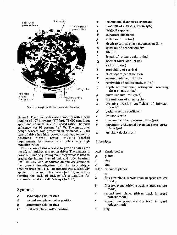
Recently a multiroller planetary traction drive was tested at the Lewis Research Center. It is shown in
figure 1 . The drive performed smoothly with a peak loading of 127 kilowatts (170 hp), 73 OOO rpm input speed and nominal 14.7 to 1 speed ratio. The peak efficiency was 95 percent (ref. 8). The multiroller design concept was presented in reference 9. This type of drive has high power capability, inherently balanced internal forces, making bearing requirements less severe, and offers very high reduction ratios.
The purpose of this report is to give an analysis for the life of multiroller traction drives.The analysis is based on Lundberg-Palmgren theory which is used to predict the fatigue lives of ball and roller bearings (ref. 10). Coy, et a1 conducted an analysis similar to the present investigation for the toroidal-type traction drive (ref. 11). The method was successfully applied to spur and helical gears (ref. 12) as well as forming the basis of fatigue life estimations for remanufactured aircraft bearings (ref. 13).
Symbols (I semimajor axis, m (in.) B second row planet roller position b semiminor axis, m (in.) C first row planet roller position
C
E e F f h K L I Q r S U
V W
Z
P
tl P
P* Y
(T
7
W
orthogonal shear stress exponent modulus of elasticity, N/m2 (psi) Weibull exponent curvature difference roller width, m (in.) depth-tocritical stress exponent, m (in.) constant of proportionality life, hr length of rolling track, m (in.) normal roller load, N Ob) radius, m (in.) probability of survival stress cycles per revolution stressed volume, m3 (in.3) semiwidth of rolling track, m (in.) depth to maximum orthogonal reversing
shear stress, m (in.) curvature sum, m-I (in.-1) life (millions of stress cycles) available traction coefficient of lubricant
design traction coefficient Poisson's ratio maximum contact pressure, GPa (psi) maximum orthogonal reversing shear stress,
angular velocity, rpm
contact
GPa (psi)
Subscripts:
A,B elastic bodies p planet r ring S sun x,y,z reference planes 1 sun 2 first row planet (driven track in speed reducer
3 first row planet (driving track in speed reducer
4 second row planet (driven track in speed
5 second row planet (driving track in speed
6 ring
mode)
mode)
reducer mode)
reducer mode)
2
Analysis Fatigue Life Model
In reference 10, Lundberg and Palmgren presented their hypothesis for the statistical relation of rolling- element bearing life to load and bearing size.The mode of failure was assumed to be subsurface originated fatigue spalling. The theory has been widely used for bearing life calculations and also provides a basis for gear life calculation which has agreed very well with the data from gear life endurance tests (ref. 14). The important parameters are number of stress cycles 9 , magnitude of critical stress T , amount of stressed volume V, and depth below the surface at which the critical stress occurs z. The stressed volume is taken as
V a wzl (1)
where I is the length of the rolling track which is traversed during one revolution of the rolling body and the semiwidth of the rolling track is designated
From reference 10, the probability of survival S, for a bearing contact is given by the following expression:
W.
This relation is consistent with experimental observations in the case of fatigue. The formula reflects the known fact that the more localized the stress is in the material (less stressed volume), the greater is the endurance. This is because on a statistical basis, there is less likelihood of a fatigue nucleation site being coincident with a condition of high stress. Conversely, there is a greater probability of a crack forming in the zone of maximum critical stress, because the material is more rapidly cycled toward failure in that region. Hence the depth to the critical stress, as well as the magnitude of the stress is important, and with each stress cycle the probability of failure increases.
From reference 1 1 , the number of stress cycles endured with 90 percent reliability is given by the following equation:
1 /e
9 = ($) Based on life testing of air-melted steel rolling- element bearings, the following values are valid for equation (3): K = 1.43 X 1095 ( S I . units), 3.58 X 1056
(english units); h = 7/3; c = 3113; and e = 10/9 (point contact), 3/2 (line contact).
Analysis of Single Contact
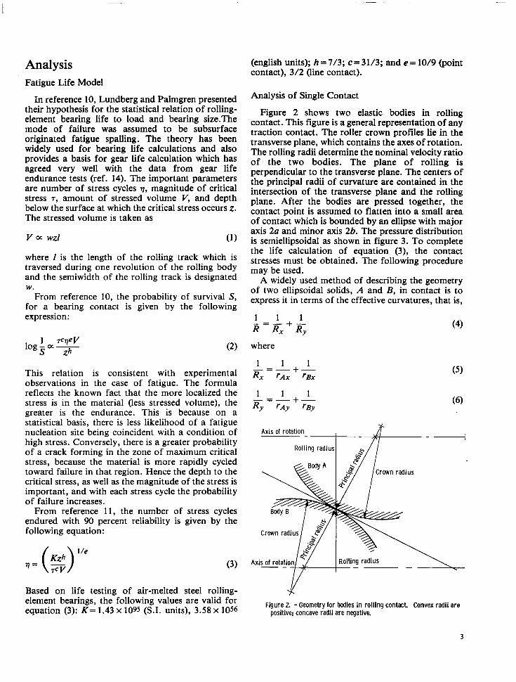
Figure 2 shows two elastic bodies in rolling contact. This figure is a general representation of any traction contact. The roller crown profiles lie in the transverse plane, which contains the axes of rotation. The rolling radii determine the nominal velocity ratio of the two bodies. The plane of rolling is perpendicular to the transverse plane. The centers of the principal radii of curvature are contained in the intersection of the transverse plane and the rolling plane. After the bodies are pressed together, the contact point is assumed to flatten into a small area of contact which is bounded by an ellipse with major axis 2a and minor axis 2b. The pressure distribution is semiellipsoidal as shown in figure 3. To complete the life calculation of equation (3), the contact stresses must be obtained. The following procedure may be used.
A widely used method of describing the geometry of two ellipsoidal solids, A and B, in contact is to express it in terms of the effective curvatures, that is,
where
1 1 1 - +- R x ~ A X rBx "-
1 1 1 R y r A y 'By
+- -" -
Axis of rotation "
Rolling radius
Axis of rotation y Rolling radius \
Figure 2. - Geometry for bodies in rolling contact. Convex radii are positive; concave radii are negative.
3
L I
Figure 3. - Contact pressure distribution. Two general curved surfaces in point contact.
The variables Rx and Ry represent the effective radius of curvature in the principal x and y planes, respectively. It is assumed that convex surfaces exhibit positive curvatures and concave surfaces, negative curvatures. Planes x and y are the respective planes of maximum and minimum relative curvature for the bodies. These planes, called the principal planes, are mutually perpendicular. Planes x and y must be chosen so that the relative curvature in plane x is greater than in plane y ; that is,
1 1 1 1 - 'Ax rBx rAy rBy
+->-+-
The radii of curvature may be positive or negative depending on whether the surfaces are convex or concave, respectively.
After the bodies are pressed together, the contact point is assumed to flatten into a small area of contact which is bounded by an ellipse with major axis 2a and minor axis 2b as shown in figure 3. Plane y contains the major axis of the contact ellipse and plane x contains the minor axis. The ratio k = a / b is called the ellipticity ratio of the contact. The values of k range from 1 to 00 for various curvature combinations of contracting surfaces. For cylinders in contact, the ellipticity ratio is 00, and the flattened area of contact is a rectangular strip. For spheres in contact, the ellipticity ratio is 1 . The first type is called line contact and all other types are called point contact.
The curvature difference is defined as
Brewe and Hamrock (ref. 15) provide simple formulas for determining the elliptic integral of the first 5 and second & kind as well as the ellipticity parameter k
5=1.528+0.602 I n 2 R RX
0.597 &=l.OOO+- (RY/RX)
0.636 k= 1.034 (I) These simple equations eliminate the need for numerical evaluation on a digital computer. These simple equations are then directly used to evaluate the semimajor a and semiminor b axis of the contact ellipse and the deformation at the center of the contact 6. Thus,
The maximum reversing orthogonal shear stress T~ occurs at a depth zo underneath the surface of contact. Expressions for these parameters can be obtained from Lundberg and Palmgren (ref. 10) as
m 2t(t + 1) T o = ~
In these equations t is an auxiliary parameter and is related to k as follows (given by private communication with Brewe and Hamrock):
t = 1 + 0.304 k-1.856 (17)
In general, the width of the rolling track is identical to the width of the contact ellipse. However, when the width of the contact pressure ellipse is exactly equal to the width of the roller, point contact is, in a practical sense, transformed into line contact. With that loading where point contact changes into line
4
t
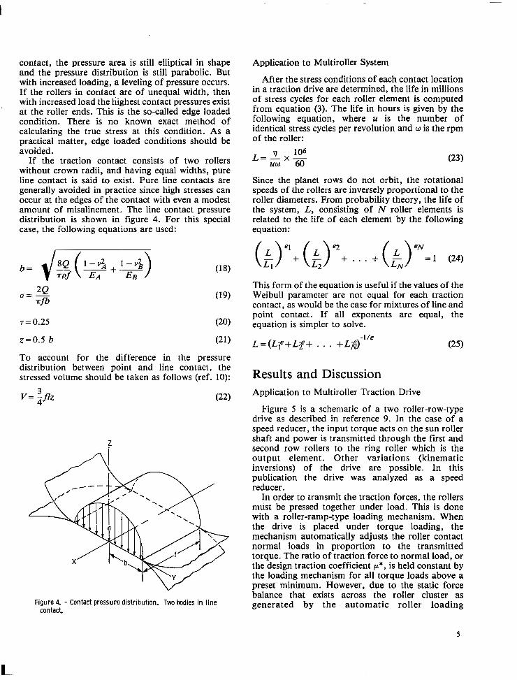
contact, the pressure area is still elliptical in shape and the pressure distribution is still parabolic. But with increased loading, a leveling of pressure occurs. If the rollers in contact are of unequal width, then with increased load the highest contact pressures exist at the roller ends. This is the so-called edge loaded condition. There is no known exact method of calculating the true stress at this condition. As a practical matter, edge loaded conditions should be avoided.
If the traction contact consists of two rollers without crown radii, and having equal widths, pure line contact is said to exist. Pure line contacts are generally avoided in practice since high stresses can occur at the edges of the contact with even a modest amount of misalinement. The line contact pressure distribution is shown in figure 4. For this special case, the following equations are used:
r = 0.25 (20)
z=0.5 b (21)
To account for the difference in the pressure distribution between point and line contact, the stressed volume should be taken as follows (ref. 10):
3 v = -flz 4 (22)
z
Figure 4. - Contact pressure distribution. Two bodies in l ine contact.
Application to Multiroller System
After the stress conditions of each contact location in a traction drive are determined, the life in millions of stress cycles for each roller element is computed from equation (3). The life in hours is given by the following equation, where u is the number of identical stress cycles per revolution and w is the rpm of the roller:
Since the planet rows do not orbit, the rotational speeds of the rollers are inversely proportional to the roller diameters. From probability theory, the life of the system, L, consisting of N roller elements is related to the life of each element by the following equation:
L1 (.>"+ L2 . . . + (.>"=1 L N (24)
This form of the equation is useful if the values of the Weibull parameter are not equal for each traction contact, as would be the case for mixtures of line and point contact. If all exponents are equal, the equation is simpler to solve.
Results and Discussion Application to Multiroller Traction Drive
Figure 5 is a schematic of a two roller-row-type drive as described in reference 9. In the case of a speed reducer, the input torque acts on the sun roller shaft and power is transmitted through the first and second row rollers to the ring roller which is the output element. Other variations (kinematic inversions) of the drive are possible. In this publication the drive was analyzed as a speed reducer.
In order to transmit the traction forces, the rollers must be pressed together under load. This is done with a roller-ramp-type loading mechanism. When the drive is placed under torque loading, the mechanism automatically adjusts the roller contact normal loads in proportion to the transmitted torque. The ratio of traction force to normal load, or the design traction coefficient p * , is held constant by the loading mechanism for all torque loads above a preset minimum. However, due to the static force balance that exists across the roller cluster as generated by the automatic roller loading
5
L
Rollerlramp n preload mechanism \'\ I '. ,+
Ring rollers
Planet reaction bearing
,-Second row planet roller
-First row planet roller
. - shaft Low speed shaft'
load occurred at the contact between the first and second row rollers. At a sun roller torque of 19.0 N-m (168 in.-lbf) this maximum Hertz stress was 1.70 GPa (246 OOO psi). The maximum Hertz stress for each contact over the range of operating sun roller . torques is shown in figure 6.
Life Analysis Without Life Adjustment Factors
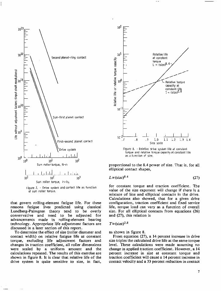
The Lundberg-Palmgren life analysis presented previously was used to determine the 10-percent (90 percent survival) fatigue life of each traction contact of the drive tested in reference 8 as a function of sun roller torque. Equation (16) was used to statistically sum up the individual contact lives, in order that an overall drive system life could be computed. Values of E appropriate for line and point contact were used as required. The results of this analysis are shown in figure 7. It is instructive to note that the life of the
Figure 5. - Cross section of Nasvytis multiroller traction drive. total drive system can never be greater than the life of the shortest lived contact. It is also clear from the slope of the straight line relation shown on the log-
I
differ on each roller contact. In order to prevent slip, La(n -3 the design traction coefficient p' at each contact is selected to be less than the available traction coefficient of the lubricated contact p. This is accomplished by choosing the proper cone angle in the roller loading mechanism. The available lubricant traction coefficient depends on many factors, such as speed, load, temperature as well as contact geometry and surface finish. For the purpose of this analysis it was assumed that the lubricant's available traction coefficient significantly exceeded the design traction coefficient of 0.05 under all operating conditions. Parametric tests (ref. 8) performed on a Nasvytis multiroller drive over the operating conditions considered here with a traction fluid established that this is a correct assumption.
The Nasvytis multiroller drive which was analyzed for life and contact stress had five rollers in each of two rows. The test drive roller cluster was approximately 0.21 meter in overall diameter and 0.06 meter in width, weighing 9 kilograms. It had a geometrical speed ratio of 14.7 to 1 . Calculations were made to a maximum power level of 149 kilowatts (200 hp) at a maximum sun roller speed of 75 000 rpm. Rolling diameter contact ratios of the drive tested in reference 8 for the sun roller - first row roller (driven track) contact, first row roller (driving tract) - second row roller (driven track) contact, and second row roller (driving track) -ring roller contact were 1.28, 3.87, and 2.97, respectively.
Stress analysis showed that the maximum contact pressure or Hertz stress for the drive at any torque
The life given in figure 7 is based on the original Lundberg-Palmgren analysis, developed about 30 years ago. The constants and exponents of variables used in their analysis were empirically determined from life tests of bearings of that time period. Since that period there has been significant progress in bearing material development and processing as well as a better understanding of the operating variables
Drive contact Sun-first planet "- First-second pla;let "- Second planet-ring
1.8c
1. 2
1. 0
" "-. "
Sun roller torque. N-m
L" 20 40 60 80 100 120 140 160 180
Sun Faller torque, in-lb.
Figure 6. - Maximum hertz stress at drive contacts a s a function of sun roller torque.
6
1 ° 1 3 F \ l o l z ~ \ \ Second planet-ring contact
L
\ Sun-first planet contact
First-second planet contact
Drive system
105 100 101 102
Sun rol ler torque. N-rn
u 101 102 103
Sun rol ler torque, in- lbf
Figure 7. - Drive system and contact l i fe as funct ion of sun rol ler torque.
that govern rolling-element fatigue life. For these reasons fatigue lives predicted using classical Lundberg-Palmgren theory tend to be overly conservative and need to be adjusted for advancements made in rolling-element bearing technology. Appropriate life adjustment factors are discussed in a later section of this report.
To determine the effect of size (roller diameter and contact width) on relative fatigue life at constant torque, excluding life adjustment factors and changes in traction coefficient, all roller dimensions were scaled by a uniform amount and the calculations repeated. The results of this exercise are shown in figure 8. It is clear that relative life of the drive system is quite sensitive to size, in fact,
t
y - k Relative torqus capacity at
t r 10-2 I J . . L - l . 8 . 9 1.0 1.1 1.2 1.3 1.4
Size scale
Figure 8. - Relative drive system life at constant torque and relative torque capacity at constant l i fe as a funct ion 0' size.
proportional to the 8.4 power of size. That is, for all elliptical contact shapes,
~a(size)8.4 (27)
for constant torque and traction coefficient. The value of the size exponent will change if there is a mixture of line and elliptical contacts in the drive. Calculations also showed, that for a given drive configuration, traction coefficient and fixed service life, torque load can vary as a function of overall size. For all elliptical contacts from equations (26) and (27), this relation is
To: (sizej2.8
as shown in figure 8. From equation (27), a 14 percent increase in drive
size triples the calculated drive life at the same torque level. These calculations were made assuming no change in applied traction coefficient. However, a 14 percent increase in size at constant torque and traction coefficient will cause a 14 percent increase in contact velocity and a 33 percent reduction in contact
7
pressure for an elliptically shaped contact. This will undoubtedly lead to a reduction in the available lubricant traction coefficient. In turn, a compensating increase in the applied traction coefficient will be required. Hence, an increase in the contact's normal load will occur. The net result will in fact reduce the size exponent in the aforementioned equation by some amount depending
. on the sensitivity of the lubricant's traction coefficient to the changes in operating conditions cited. For example, if a 14 percent increase in size for a given lubricant at a particular operating speed and torque causes a 10 percent loss in the available traction coefficient, drive life will be 2.3 times longer instead of three times longer when changes in traction coefficient are ignored.
Life Adjustment Factors
Advancements in rolling-element bearing technology have produced bearing designs which, for a given application, have increased fatigue lives. A better understanding of the variables that affect fatigue life and the use of improved materials and manufacturing techniques have resulted in rolling- element bearing lives that are often many times those which Lundberg-Palmgren theory predicts. In recognition of these improvements life adjustment factors have been developed in reference 5 for providing a more accurate prediction of rolling- element bearing life. In view of the similarity in contact geometry, materials, lubricating factors, operating conditions and failure modes, several of these factors developed for rolling-element bearings are considered to be equally applicable to the multiroller traction drive. The life adjustment factors to be considered here are the materials factor, material processing factor and lubrication factor.
All of the rolling traction elements in the Nasvytis multiroller traction drive are made from consumable electrode vacuum melted (CVM) materials (ref. 8). The sun roller is made from through-hardened CVM AISI-52100 bearing steel with a Rockwell-C hardness of 61 to 63. According to reference 5 , in a bearing application, the use of CVM AISI-52100 steel would result in a combined material and processing life multiplication factor of 6 . The other traction components are manufactured from CVM SAE-9310 steel that is case carburized to a Rockwell-C hardness of 60 to 63. Reference 5 suggests that the use of this material will give a life multiplication equivalent to through-hardened CVM AISI-52100.
It is well known that the thickness of lubricant film which separates contacting machine elements can have a strong influence on the contacts' fatigue life. In reference 5 , the effectiveness of a lubricant film in terms of the ratio of film thickness to composite!
surface roughness h/u is related to fatigue life. The composite surface roughness is defined by
where UA and u~ are the surface finishes of the mating bodies. The lubricant-fatigue factor has been assigned a value of 1.0 when h/u has a value of approximately 1.3. Details of the film thickness calculation using the Archard and Cowking formula recommended in reference 5 are given in reference 11. The lubricant used in the Nasvytis multiroller traction drive in reference 8 was a synthetic cycloaliphatic traction lubricant, and the roller surface roughnesses were less than 0.2 pm (8 pin.) rms. A contact inlet temperature of 344 K (160" F) was assumed. Due to inlet shear heating and starvation effects, it is unlikely that the minimum EHD film thickness would exceed the composite surface roughness by more than a factor of 4 (ref. 16). Accordingly, the h/u ratio in this investigation will be limited to a value of four.
One additional factor not treated in reference 5 but important to traction drive contacts is the potentially deleterious effect which traction itself has on the rolling-element fatigue life of the contacting elements. Some investigations (ref. 17) have found a decrease in life in rolling-element fatigue tests in which some sliding or traction is introduced. Fatigue tests (ref. 18) with increased spin (i.e., rotational sliding within the contact area) also showed a reduction in fatigue 1ife.The analysis of reference 20 has shown that tangential or traction contact forces reduce the depth at which the maximum shearing stress occurs. Since, in the Lundberg-Palmgren theory (ref. lo), life theoretically decreases with a decrease in the depth to the maximum orthogonal reversing shear stress (see eq. (3)), traction forces may act to reduce contact fatigue life. To account for this reduction an additional life adjustment factor, the traction factor, will be introduced. Given the fact that little conclusive traction contact fatigue life data is available, this factor for the purposes of this analysis will be arbitrarily given a value for all contacts of 0.5. This factor can be treated as an arbitrary bit of conservatism until more definitive values can be determined.
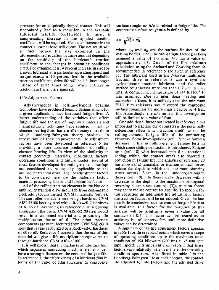
A summary of the life adjustment factors appears in table I for three typical points which cover a range of operating conditions up to the maximum rated condition of 194 kilowatts (200 hp) at 75 000 rpm input speed. It is apparent from table 1 that these factors vary relatively little over the entire operating condition spectrum. Also listed in table I is the Lundberg-Palmgren life at each contact, the contact life adjusted for life factors and the adjusted drive
8
TABLE 1. -SUMMARY OF CONTACT CONDITIONS, LIFE ADJUSTMENT FACTORS AND DRIVE LIFE FOR THREE DRIVE OPERATING CONDITIONS
Second First- planet- second first planet- second Second First- Sun- Second
planet ring planet planet ring
16.6 kW (22.2 hp) 74.6 kW (100 hp) 149 kW (200 hp) 75 000-rpm sun speed 75 000-rpm sun s p e d
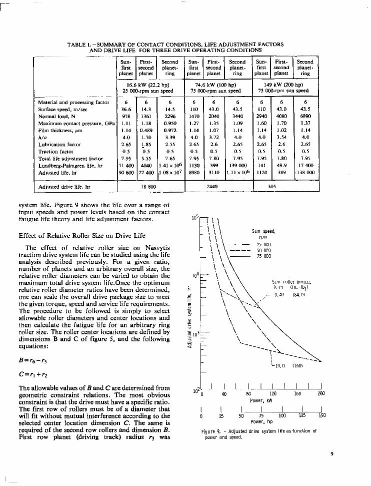
system life. Figure 9 shows the life over a range of input speeds and power levels based on the contact fatigue life theory and life adjustment factors.
Effect of Relative Roller Size on Drive Life
The effect of relative roller size on Nasvytis traction drive system life can be studied using the life analysis described previously. For a given ratio, number of planets and an arbitrary overall size, the relative roller diameters can be varied to obtain the maximum total drive system 1ife.Once the optimum relative roller diameter ratios have been determined, one can scale the overall drive package size to meet the given torque, speed and service life requirements. The procedure to be followed is simply to select allowable roller diameters and center locations and then calculate the fatigue life for an arbitrary ring roller size. The roller center locations are defined by dimensions B and C of figure 5 , and the following equations:
B z r 6 - r ~
C=rl + r 2
The allowable values of E and Care determined from geometric constraint relations. The most obvious constraint is that the drive must have a specific ratio. The first row of rollers must be of a diameter that will fit without mutual interference according to the selected center location dimension C. The same is required of the second row rollers and dimension E . First row planet (driving track) radius r 3 was
Sun speed,
Sun rol ler torqua, N-m (in. -Ibf)
,- 9.<9 (84.0)
102 1, I 0
I- 19.0 168)
I I . I "' 40 80 120 160 2M1
Power, kW
1 1. .A 25 50 75 100 125 150
Power, h p
Figure 9. - Adjusted drive system l i fe as function of power and speed.
9
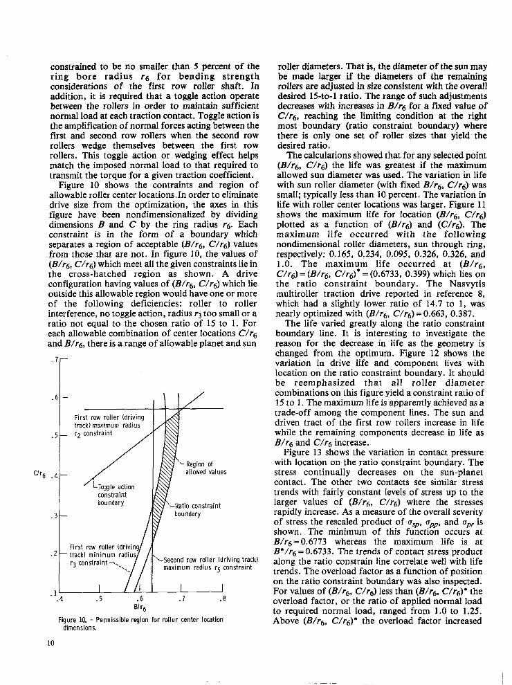
constrained to be no smaller than 5 percent of the ring bore radius r6 for bending strength considerations of the first row roller shaft. In addition, it is required that a toggle action operate between the rollers in order to maintain sufficient normal load at each traction contact. Toggle action is the amplification of normal forces acting between the first and second row rollers when the second row rollers wedge themselves between the first row rollers. This toggle action or wedging effect helps match the imposed normal load to that required to transmit the torque for a given traction coefficient.
Figure 10 shows the contraints and region of allowable roller center 1ocations.h order to eliminate drive size from the optimization, the axes in this figure have been nondimensionalized by dividing dimensions B and C by the ring radius f 6 . Each constraint is in the form of a boundary which separates a region of acceptable (B/fg, c/fg) values from those that are not. In figure 10, the values of (B/rg, c/fg) which meet all the given constraints lie in the cross-hatched region as shown. A drive configuration having values of (B/fg, c/fg) which lie outside this allowable region would have one or more of the following deficiencies: roller to roller interference, no toggle action, radius r3 too small or a ratio not equal to the chosen ratio of 15 to 1. For each allowable combination of center locations c/fg and B/fg , there is a range of allowable planet and sun
‘Ir6 .
. 7 -
6 -
5 -
4 -
3 -
2 -
1- . 4
First row roller (driving track) maximum radius
boundary
r3 constraint -,..
.5 .6 BI ‘6
allowed values
LRat io constraint
‘“Second row roller (driving track) maximum radius r5 constraint
a . 7 .a
Figure 10. - Permissible region for roller center location dimensions.
roller diameters. That is, the diameter of the sun may be made larger if the diameters of the remaining rollers are adjusted in size consistent with the overall desired 15-to-1 ratio. The range of such adjustments decreases with increases in B/r6 for a fixed value of c/fg, reaching the limiting condition at the right most boundary (ratio constraint boundary) where there is only one set of roller sizes that yield the desired ratio.
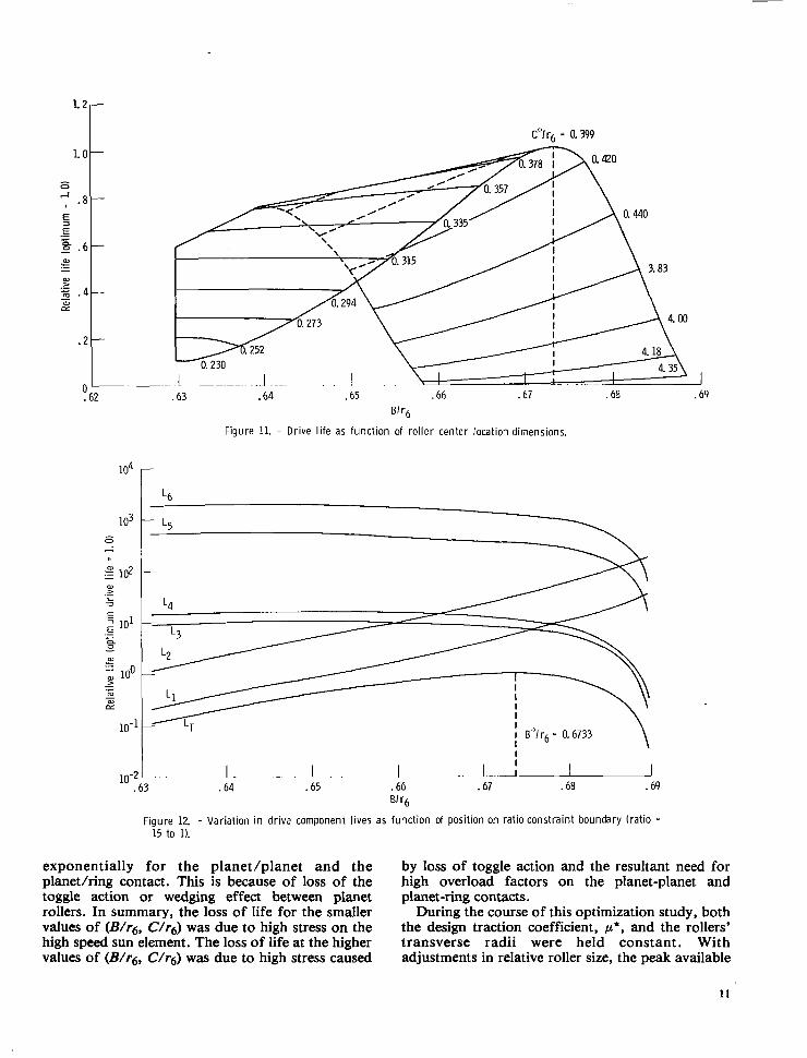
The calculations showed that for any selected point (B/fg, c/fg) the life was greatest if the maximum allowed sun diameter was used. The variation in life with sun roller diameter (with fixed B/fg , c/fg) was small; typically less than 10 percent. The variation in life with roller center locations was larger. Figure 11 shows the maximum life for location (B/rg, c/fg) plotted as a function of (B/rg) and (c/fg). The maximum life occurred with the following nondimensional roller diameters, sun through ring, respectively: 0.165, 0.234, 0.095, 0.326, 0.326, and 1.0. The maximum life occurred at (B/fg, c/fg) = (B/fg, c/fg)* = (0.6733, 0.399) which lies On the ratio constraint boundary. The Nasvytis multiroller traction drive reported in reference 8 , which had a slightly lower ratio of 14.7 to 1, was nearly optimized with (B/fg, c/fg) =0.663, 0.387.
The life varied greatly along the ratio constraint boundary line. It is interesting to investigate the reason for the decrease in life as the geometry is changed from the optimum. Figure 12 shows the variation in drive life and component lives with location on the ratio constraint boundary. It should be reemphasized that all roller diameter combinations on this figure yield a constraint ratio of 15 to 1 . The maximum life is apparently achieved as a trade-off among the component lines. The sun and driven tract of the first row rollers increase in life while the remaining components decrease in life as B/rg and c/fg increase.
Figure 13 shows the variation in contact pressure with location on the ratio constraint boundary. The stress continually decreases on the sun-planet contact. The other two contacts see similar stress trends with fairly constant levels of stress up to the larger values of (B/fg, c/fg) where the stresses rapidly increase. As a measure of the overall severity of stress the rescaled product of asp, upp, and upr is shown. The minimum of this function occurs at B/f,j=0.6773 whereas the maximum life is at B*/f6=0.6733. The trends of contact stress product along the ratio constrain line correlate well with life trends. The overload factor as a function of position on the ratio constraint boundary was also inspected. For values of (B/fg, c/fg) less than (B/fg, C/fg)* the overload factor, or the ratio of applied normal load to required normal load, ranged from 1 .O to 1.25. Above (B/fg, c/fg)* the overload factor increased
10
Bf '6
Figure 11. - Drive l i fe as function of roller center locatio? dimensions.
I
i lo-263 - I . ~ I . . I .. l . . L L I
.64 .65 .66 .67 .68 .69 51 '6
Figure 12. - Variat ion in driva component l ives as function of posi t ion on rat io constraint boundary ( rat io =
15 to 1).
exponentially for the planet/planet and the by loss of toggle action and the resultant need for planetlring contact. This is because of loss of the high overload factors on the planet-planet and toggle action or wedging effect between planet planet-ring contacts. rollers. In summary, the loss of life for the smaller During the course of this optimization study, both values of (B/& c/4) was due to high stress on the the design traction coefficient, p * , and the rollers' high speed sun element. The loss of life at the higher transverse radii were held constant. With values of (B/f6, c/&) was due to high stress caused adjustments in relative roller size, the peak available
11
I I
K'lrh = 0.6733
3 .64 .65 .66 .67 .68 .69 BI '6
Figure 13. - Variat ion in contact pressure as func t i on of posit ion on rat io constraint boundary.
traction coefficient of the lubricant will vary somewhat and may necessitate a small change in p * . However, variations in p* would be expected to have a relatively minor effect on the results of this study. With regard to the roller's transverse radii, it is clear that changes in the transverse geometry, such as roller width for line contact or crown radius for elliptical contact, can cause significant variations in contact stresses and contact life. In selecting the proper transverse roller radii, other considerations such as the effect on the available traction coefficient, spin velocities, and efficiency should be addressed.
Another constraint on this analysis is that the basic drive configuration of two rows of five planet rollers each was not varied. However, depending on the requirements of size and ratio, a drive with some other number of planet rollers may exhibit a higher drive system life. For a truly optimized drive design method, the traction coefficienct and transverse contact geometry would be varied, and the entire procedure repeated for different numbers of rollers and planet rows until a maximum life was found.
Concluding Remarks The analysis presented deals with only one of the
factors that should be considered when designing a traction drive. Although fatigue life is important, the questions of drive-roller stability and efficiency should also be addressed. Since traction drives, unlike gearing, rely heavily on the amount of traction that can be generated within the contact, the lubricant, operating conditions, contact geometry, and surface finish must be carefully selected on the basis of both performance and life. Although traction drives relative to other drive mechanisms are remarkably simple in principle, the technology involved in arriving at the best design is rather sophisticated.
Summary of Results A contact fatigue life analysis for a Multiroller
Planetary Traction Drive was performed. The life analysis takes account of stress, stressed volume, and
12
depth of occurrence of the critical stress. The methodology is based on a modification of the well- known Lundberg-Palmgren theory. A design traction coefficient of 0.05 was maintained. Life adjustment factors were included in the analysis based on advancements in rolling-element bearing technology in the area of materials, processing, lubrication and design. Elastohydrodynamic film thickness calculations were made for representative operating conditions, and the possible adverse effects of traction on rolling contact life were considered.
The following results were obtained from a study of a 14.7 to 1 ratio, Nasvytis Multiroller Traction Drive with two rows of five-stepped planet rollers each in a 9-kilogram cluster of approximately 0.21 meter diameter and 0.06 meter width having sun roller-first row roller (driven track) contact, first row roller (driving track)-second row roller (driven track) contact and second row (driving track)-ring roller contact ratios of 1.28, 3.87, and 2.97, respectively:
1. The total drive system Lundberg-Palmgren 10-percent fatigue life with life adjustment factors ranged from 18 800 hours at 16.6 kilowatts (22.2 hp) and 25 OOO rpm sun roller speed to 305 hours at 149 kilowatts (200 hp) and 75 OOO rpm, with a life rating of 2440 hours at a nominal operating condition of 74.6 kilowatts (100 hp) and 75 OOO rpm.
2. For a given ratio and number of planets an optimum combination of roller diameters and center locations exists for maximum drive system life.
3. The shortest lived contact was the first planet- second planet contact since the highest maximum Hertz stress occurred there.
4. For a given fatigue life, traction coefficient and drive configuration, torque capacity is proportional to the 2.8 power of overall drive size. For elliptical contact shapes and constant torque drive, life is proportional to the 8.4 power of size.
Lewis Research Center, National Aeronautics and Space Administration, Cleveland, Ohio, August 29, 1980.
References 1. Carson, Robert W.: Traction Drives Update. Power Trans-
mission Design, vol. 19, no. 11. Nov. 1977, pp. 37-42.
2. Dvorak, D. Z.: Your Guide to Variable-Speed Mechanical Drives. Product Engineering, vol. 34, Dec. 23, 1963, pp.
3. YeaDle. F.: Metal-to-Metal Traction Drives Now Have a New 63-74.
4.
5 .
6.
7.
8.
9.
10.
11.
12.
13.
14.
15.
16.
17.
18.
19.
Lease on Life. Product Engineering, vol. 42, no. 15, Oct.
Carson, Robert W.: New and Better Traction Drives are Here. Mach. Des., vol. 46, no. 10, Apr. 18, 1974, pp. 148-155.
Bamberger, E. N., et al.: Life Adjustment Factors for Ball and Roller Bearings -An Engineering Design Guide. American Society of Mechanical Engineers, 1971.
Hewko, L. 0.: Roller Traction Drive Unit for Extremely Quiet Power Transmission. J . Hydronautics, vol. 2, no. 3,
Savage, M.; and Loewenthal, S. H.: Kinematic Stability of Roller Pairs in Free-Rolling Contact. NASA TN D-8146, 1976.
Loewenthal, S. H.; Anderson, N. E.; and Nasvytis, A. L.: Performance of a Nasvytis Multiroller Traction Drive.
Nasvytis, A. L.: Multiroller Planetary Friction Drives. SAE Paper 660763, Oct. 1966.
Lundberg, G.; and Palmgren, A.: Dynamic Capacity of Roll- ing Bearings. Ingenioervetenskapskad. - Handl., no. 196, 1947.
Coy, J. J.; Loewenthal, S. H.; and Zaretsky, E. V.: Fatigue Life Analysis for Traction Drives with Application to a Toroidal Type Geometry. NASA TN D-8362, 1976.
Coy, J . J . ; Townsend, D. P.; and Zaretsky, E. V.: Dynamic Capacity and Surface Fatigue Life for Spur and Helical Gears. J . Lubr. Technol., vol. 98, no. 2, Apr. 1976, pp.
Coy, J. J.; Zaretsky. E. V.; and Cowgill, G . R.: Life Analysis of Restored and Refurbished Bearings. NASA TN D-8486, 1977.
Townsend, D. P.; Coy, J . J.; and Zaretsky, E. V.: Experimen- tal and Analytical Load-Life Relation for AIS1 9310 Steel Spur Gears. J . Mech. Des., vol. 100, no. 1, Jan. 1978, pp. 54-60.
Brewe, D. E. and Hamrock, B. J.: Simplified Solution for Elliptical Contact Deformation Between Two Elastic Solids. J. Lubr. Technol., vol. 99, no. 4, Oct. 1977, pp. 485-487.
Coy, J. J.; Gorla, R. S. R.; and Zaretsky. E. V.: Comparison of Predicted and Measured Elastohydrodynamic Film Thickness in a 20-Millimeter-Bore Ball Bearing.
Diaconescu, E. N.; Kerrison, G. D.; and MacPherson, P. B.: A New Machine for Studying the Effects of Sliding and Traction on the Fatigue Life of Point Contacts, with Initial Test Results. ASLE Trans., vol. 18, no. 4, Oct. 1975, pp.
Zaretsky, E. V.; Anderson, W. J.; and Parker, R. J.: The Effect of Contact Angle on Rolling-Contact Fatigue and Bearing Load Capacity. ASLE Trans., vol. 5, 1962, pp.
Smith, J . 0.; and Liu, C. K.: Stresses Due to Tangential and Normal Loads on an Elastic Solid with Application to Some Contact Stress Problems. J. Appl. Mech., vol. 20, no. 2, June 1953, pp. 157-166.
~.
1971, pp. 33-37.
July 1968, pp. 160-167.
AVRADCOM-TR-78-36, NASA TP-1378, 1978.
267-276.
AVRADCOM-TR-79-20, NASA TP-1542, 1919.
239-248.
210-219.
13
1. Report No. NASA TP-1710 3. Recipient's Catalog No. 2. Government Accession No.
AVRADCOM TR 80-C-16 1 4. Title and Subtitle
LIFE ANALYSIS OF MULTIROLLER PLANETARY TRACTION DRIVE 6. Performing Organization Code
John J. Coy, Douglas A. Rohn, and Stuart H. Loewenthal E-484 10. Work Unit No.
9. Performing Organization Name and Address NASA Lewis Research Center AVRADCOM Research and Technology Laboratories Cleveland, Ohio 44135
National Aeronautics and Space Administration Technical Paper Washington, D. C. 20546 and U. S. Army Aviation Research and 14. Sponsoring Agency Code
Development Command, St. Louis, Mo 63166
John J. Coy, Propulsion Laboratory, AVRADCOM Research and Technology Laboratories, Lewis Research Center, Cleveland, Ohio; Douglas A. Rohn and Stuart H. Loewenthal, Lewis Research Center.
11. Contract or Grant No,
2. Sponsoring Agency Name and Address 13. Type of Report and Period Covered
5. Supplementary Notes
6. Abstract
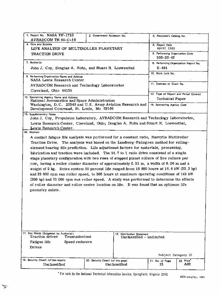
A contact fatigue life analysis was performed for a constant ratio, Nasvytis Multiroller Traction Drive. The analysis was based on the Lundberg-Palmgren method for rolling- element bearing life prediction. Life adjustment factors for materials, processing, lubrication and traction were included. The 14.7 to 1 ratio drive consisted of a single stage planetary configuration with two rows of stepped planet rollers of five rollers per row, having a roller cluster diameter of approximately 0.21 m, a width of 0.06 m and a weight of 9 kg. Drive system 10 percent life ranged from 18 800 hours at 16.6 kW (22.2 hp) and 25 000 rpm sun roller speed, to 305 hours at maximum operating conditions of 149 kW (200 hp) and 75 000 rpm sun roller speed. A study was performed to determine the effects of roller diameter and roller center location on life. It was found that an optimum life geometry exists.
I. Key Words (Suggested by Author(s)) Traction drives Transmissions
18. Distribution Statement Unclassified - unlimited
Fatigue life Speed reducers Drives
I Subject Category 37
21. No. of Pages 22. Price' . Security Classif. (of this report) 20. Security Classif. (of this page)
Unclassified A02 15 Unclassified
* For Sale by the National Technical Information Service, Springfield, Virginia 22161 NASA-Langl ey , 1981
National Aeronautics and Space Administration
Washington, D.C. 20546
S P E C I A L -FOURTH C L A S S M A I L BOOK
-
. ,
Postage and Fees Paid National Aeronautics and Space Administration N A S A 4 5 1
' Official Business .' - Penalty for Private Use, $300 . I