ARIZONA STATE UNIVERSITY SCHOOL OF SUSTAINABLE ENGINEERING AND THE BUILT ENVIRONMENT Life Cycle Assessment of Residential Solid Oxide Fuel Cells Seth Herron SSEBE-CESEM-2012-CPR-001 Course Project Report Series May 2012
Transcript
ARIZONA STATE UNIVERSITY
SCHOOL OF SUSTAINABLE ENGINEERING AND THE BUILT ENVIRONMENT
Life Cycle Assessment of Residential Solid Oxide Fuel Cells
Life Cycle Assessment of Residential Solid Oxide Fuel Cells
Seth Herron
Arizona State University
CEE 598: Life Cycle Assessment for Civil Systems Dr. Mikhail Chester
May 1st, 2012
Executive Summary
Because of the relatively large amount of water needed to generate electricity at traditional power plants,
the electricity sector’s ability to meet demand can become compromised when local water resources become scarce.
The goal for energy/water managers moving forward is to develop coupled water/energy systems that are more
resilient to climate induced shocks, such as drought and heat waves. One of the options suggested to increase the
resilience of water/energy systems is the introduction of decentralized elements, such as solar panels, fuel cells, and
water reuse. Solid oxide fuel cells (SOFC) are particularly suited for this application. However, if SOFCs were to be
widely adopted for residential and commercial applications, their emissions would be released into a largely urban
environment. Despite the benefit they would provide in relaxing the water demand of electricity production, they
may have a negative impact on urban air quality.
This study seeks to examine how the introduction of residential SOFCs will affect urban air quality. Both
the life-cycle and operations emissions profiles of an SOFC are compared with the baseload electricity generating
technologies that widespread adoption of SOFCs would replace – coal fired, natural gas combined cycle, and
nuclear. The monetary impacts from use phase emissions are then assessed in five water-vulnerable cities in which
SOFCs would likely be adopted in order to increase local resilience to electricity failures as a result of water
shortages.
The SOFC system under study is a 1 kWe system of planar design intended for residential CHP. The excess
heat from the SOFC is used to heat domestic hot water. Analysis of the SOFC system life-cycle includes raw
materials extraction and processing, component manufacturing, SOFC manufacturing, natural gas fuel processing
and distribution, SOFC use, as well as energy used in these processes. Life-cycle analysis of the baseload power
systems is bounded similarly. Emissions tracked for this study include SOx, NOx, VOCs, PM10, and PM2.5.
LCA data for SOFC manufacturing is taken from Karakoussis et al 2000. SOFC use-phase data is taken
from manufacturer catalogues. Data for manufacturing, operation, and maintenance of coal-fired, NGCC, and
nuclear power plants are taken from GREET1 and GREET2. LCA data for fuel feedstocks is taken from GREET2.
End of life scenarios are not included in this study. For use-phase impact assessment, the APEEP model is used to
calculate monetary impacts of emissions. The counties to which use-phase SOFC emissions are attributed are those
that have been identified as being vulnerable to electricity outages due to water shortages. Use-phase electric power
plant impacts are attributed to the counties in which local production is dominant.
LCA results show that, for most emission categories, the SOFC system has better performance than the
larger power plants. Life cycle emissions for most emission types are negative in the case of SOFCs. This is the
result of the emission offsets from water heaters. States that have electricity generation mixes dominated by coal
(Georgia, for example) have higher offsets than states whose electricity generation is dominated by natural gas
(California). In this way, using the more efficient system of a SOFC for CHP actually produces a negative effect on
total emissions by obviating the need for emission-producing water heating. The impact assessment for the use
phase of SOFCs and traditional power plants show similar results, with SOFC systems offsetting impacts from water
heaters (thus, having ‘negative’ impacts).
These results show that SOFCs are most likely safe to use in urban areas. The emissions that would be
directly released into urban areas (during the use phase) are lower than those of other electricity generating
technologies. When water heater offsets (both natural gas and electric) from using the SOFCs for CHP are factored
in, SOFCs actually reduce emissions impacts.
This study has shown that, aside from the benefit they provide for reducing water used in electricity
generation, fuel cells also provide the benefit of reducing pollutants through CHP offsets. By computing the total
monetary impact reduction that results from using SOFCs, cities and counties may find that there are additional
benefits to providing subsidies to homeowners for this new technology.
Background
Energy and water are interrelated. Power generation requires water for cooling and steam generation
(approximately 25 gallons per kWh produced), and water delivery requires power for treatment and pumping
(NETL, 2006). Additionally, utilities must provide both reliable power and water to users. Because of the critical
linkages between water and energy systems, they are vulnerable to disruptions when one system becomes stressed.
During the past decade, countries such as France, Germany, Spain, and India, were forced to shut down power plants
due to water shortages, leaving users with spotty electrical service (Jowit & Espinoza, 2006; Hardikar & Mehta,
2008). In 2008, in the Southeastern United States, a severe drought nearly caused regional energy managers to
deactivate 24 nuclear power plants (representing 23% of U.S. nuclear power) for lack of cooling water (NETL,
2009). Additionally, at least 22 metropolitan areas in the United States alone (including Atlanta, Chicago, Houston,
New York, and San Francisco) are projected to see water shortages as a result of electricity generation (or vice
versa) by 2025 (Sovacool & Sovacool, 2009).
The goal for energy/water managers moving forward is to develop coupled water/energy systems that are
more resilient to climate induced shocks, such as drought and heat waves. One of the options suggested to increase
the resilience of water/energy systems is the introduction of decentralized elements, such as solar panels, fuel cells,
and water reuse (Pandit et al, under review). Technologies that can be used for combined heating and power (CHP)
are especially promising because they are able to channel what would normally be wasted heat in electricity
generation to a useful purpose such as space or water heating, thus greatly increasing efficiency in resource use.
Solid oxide fuel cells (SOFC) are particularly suited for this application. SOFCs, like other fuel cells,
convert chemical energy stored in gaseous fuels into usable electrical energy. Fuel cells bypass direct combustion of
the fuel using a carefully controlled environment where electrons are split from the fuel, then forced through a
circuit to create an electrical current. Unlike other fuel cells, however, SOFCs utilize either a solid ceramic or a solid
metal oxide as their membrane. By using ceramics or metal oxides, SOFCs can operate at very high temperatures
ranging from 600-1000°C (Stambouli, 2002). When this excess heat is utilized for CHP, SOFCs can achieve total
efficiencies (electric plus thermal) of up to 90%. Unlike some other types of fuel cells which require pure hydrogen
gas to operate, SOFCs, because their high operating temperatures allows for internal fuel reformation, are frequently
powered using natural gas and therefore have a relatively low emissions profile – producing mostly CO2. However,
if SOFCs were to be widely adopted for residential and commercial applications, their emissions would be released
into a largely urban environment. Despite the benefit they would provide in relaxing the water demand of electricity
production, they may have a negative impact on urban air quality.
Research Statement
This study seeks to examine how the introduction of residential SOFCs will affect urban air quality. Both
the life-cycle and operations emissions profiles of an SOFC are compared with the baseload electricity generating
technologies that widespread adoption of SOFCs would replace. The monetary impacts from use phase emissions
are then assessed in five water-vulnerable cities in which SOFCs would likely be adopted in order to increase local
resilience to electricity failures as a result of water shortages.
Scope and System Boundary
The purpose of this study is to examine both life-cycle emissions and direct use-phase impacts of an SOFC
used for CHP. These results are then compared to life-cycle emissions and use-phase impacts from three sources of
baseload electric power: a coal plant, a nuclear plant, and a natural gas combined cycle (NGCC) power plant.
Impacts are calculated for five urban areas: Phoenix, San Francisco, Atlanta, Chicago, and Houston.
The SOFC system under study is a 1 kWe system of planar design intended for residential CHP. The
system diagram is shown in Figure 1. The SOFC has an electrical efficiency of 45% and a thermal efficiency of 45%
- for every 1 kWh of electricity produced by the cell, another 1 kWh of heat usable heat is produced. The excess heat
from the SOFC is used to heat domestic hot water. The SOFC uses natural gas as a fuel, and operates continuously
throughout its 20-year lifetime. The fuel cell stack has a lifetime of 5 years and must be replaced accordingly
(Stambouli, 2002). In this system, the SOFC supplements, but does not replace, a traditional water heater.
Analysis of the SOFC system life-cycle includes raw materials extraction and processing, component
manufacturing, SOFC manufacturing, natural gas fuel processing and distribution, SOFC use, as well as energy used
in these processes. Not included in the analysis are the energy and materials inputs of the equipment and buildings
used to manufacture the SOFCs. Also not included are impacts from end of life scenarios for the SOFC system.
Life-cycle analysis of the baseload power systems is bounded similarly. Included in the system boundaries
are materials extraction and processing for the power plants, fuel extraction and processing, and emissions from the
operation and maintenance of the plants. End of life scenarios are not included in the analysis.
All systems are compared based on the emissions required to deliver 1 kWh of electricity to a user. Impacts
from manufacturing are divided over the lifetime of the technology. Emissions tracked for this study include SOx,
NOx, VOCs, PM10, and PM2.5.
Figure 1: A system diagram of the SOFC (from Karakoussis et al 2000).
Methods
There have not been many comprehensive life-cycle assessments of SOFCs. One conducted by Karakoussis
et al 2000, however, is consistently cited in the literature, and is used as a data source for this study. Karakoussis et
al 2000 seeks to compare the life-cycle impacts from two different designs of solid oxide fuel cells – a planar design
to be used in small cells, and a tubular design to be used in large cells. Because of its application for small,
residential units used for CHP, the results of the LCA of the planar SOFC design were used for this analysis.
Karakoussis et al 2000 used primary data from the projected manufacturing processes of a Sulzer Hexis 1 kWe
SOFC. Figure 2 shows the respective system boundaries of the study by Karakoussis et al 2000 and this one.
Figure 2: System boundaries for the analysis and the one conducted by Karakoussis et al 2000 (diagram initially from Karakoussis et al 2000 and modified to show the difference in system boundaries).
Karakoussis et al 2000 separates impacts from the materials and manufacturing of the SOFC into two main
components – the stack and the balance of plant. For this analysis, stack emissions are accounted for four times to
simulate stack replacement over the 20-year lifetime of the SOFC.
In Karakoussis et al 2000, SOFC manufacturing is assumed to be powered by a natural gas combined cycle
electricity plant. For this study, direct manufacturing process data was taken from industry sources, while impacts
related to material extraction and processing were sourced from literature, LCA databases, and contacts with
manufacturing companies.
For this study, emissions data for operation of the SOFC are sourced from industry catalogues for larger
SOFC systems (assumed to scale down linearly) that use natural gas as a fuel source currently on the market (UTC
Power, 2008; Fuel Cell Energy, 2010). Linear scaling for the larger systems is reasonable because the larger systems
extract fuel from natural gas using the exact same process. Emissions should be the same as long as the content of
the natural gas is the same. Upstream impacts from natural gas processing are taken from the Argonne National Lab
LCA tool, GREET1.
SOFC particulate emissions are only given as ‘particulates’ in the literature. PM10 and PM2.5 values are
derived using assumptions from GREET. According to GREET, for the manufacturing of all electricity plants, the
ratio of PM10 to PM2.5 emissions are roughly 3:1. So, particulates from mechanical processes in SOFC
manufacturing are allocated accordingly. This assumption is consistent with the heuristic that the majority of PM
emissions from mechanical processes are PM10 rather than PM2.5. Also, according to GREET, particulate
emissions from natural gas combustion are split evenly between PM10 and PM2.5. SOFC particulate emissions for
the use-phase are also allocated in this way. PM emissions from energy used in SOFC manufacturing is divided
evenly – reflecting the fact that Karakoussis et al 2000 assumes energy from manufacturing to come from a NGCC
power plant.
Because, ultimately, we are interested in the impacts of widespread SOFC adoption rather than the impacts
from a single user, the water heater emission offsets must be representative of the population. From the 2009 EIA
Residential Energy Consumption Survey, we estimate that half the SOFC adopters use a natural gas water heater,
and half use an electric heater. So, in calculating water heater offsets, an average is taken between the emissions of a
natural gas water heater and an electric water heater.
Natural gas water heater offsets are derived by averaging emissions values from three sources, GREET
(natural gas boiler), Ossman 2006 (ultimately taken from a 1995 EPA study), and natural gas emission factors taken
from the EPA (EPA, 1998). The natural gas water heater is assumed to be 60% efficient (ACEEE, 2011).
Electric water heater offsets are derived from the electricity LCA data provided by GREET. Regional
electricity mixes are constructed using data taken from the EIA (EIA, 2012). The electric water heater is assumed to
be 90% efficient (ACEEE, 2011).
Additionally, from a previous experience modeling SOFCs for CHP in residential applications, we know
that some of the usable heat from SOFCs is wasted to prevent domestic hot water from boiling (Herron and
Williams, under review). The amount of heat that gets wasted depends on the local climate and the hot water use
profile of the residence. Each location has a different hot water use factor that alters the emissions offset by the
SOFC. The Table 1 presents the hot water use factors for the five cities under analysis.
Table 1: Hot Water Use Factors
State Phoenix, AZ San Francisco, CA Atlanta, GA Chicago, IL Houston, TX Hot Water Use Factor 0.662 0.745 0.812 0.898 0.76
The LCA of the electricity plants is conducted using data from GREET. GREET contains data for direct
plant emissions, upstream emissions from primary fuel extraction and processing, and emissions from plant
construction, operation, and maintenance (emissions from plant construction, operation, and maintenance is derived
using GREET2) (Sullivan et al, 2010). Analysis was conducted on three traditional power plant types: Coal-fired,
Natural Gas Combined Cycle, and Nuclear (LWR) for electrolysis to G.H2 at refueling station.
Impact assessment for the use phase of SOFCs and traditional power plants is conducted using The Air
Pollution Emission Experiments and Policy analysis model (APEEP) developed by Muller and Mendelsohn 2009.
APEEP puts a monetary value on national emissions impacts, broken down to the county level. For each of the
urban areas under study, we identify counties where impacts are likely to occur. Then, the emissions released in
those counties are converted to dollars worth of impact using data from APEEP. The impacts evaluated by APEEP
are SOx, NOx, VOCs, PM10, PM2.5, and ammonia. However, no data could be gathered on ammonia emissions, so
it was excluded from the LCIA.
Counties slated for SOFCs (where the emissions impacts are located) are those that have been identified as
being vulnerable to water shortages due to electricity production (Sovacool and Sovacool, 2009). Direct emissions
impacts are attributed to these locations. When calculating these use-phase impacts, SOFC emissions and natural gas
heater offsets are attributed to the county in which the SOFCs are ‘placed’. Emission offsets from the electric water
heater are attributed proportionally according to the location of the electricity mix. For example, the proportion of
the state electricity mix devoted to coal is attributed to the county in which much of state coal production takes
place.
Use-phase electric power plant impacts are attributed to the counties in which local production is dominant.
For example, in the San Francisco area, most natural gas power plants are located in Contra Costa County. So,
Contra Costa is the county to which the total emissions impacts are attributed. (Also, the San Francisco area is the
only locality that does not contain a coal or nuclear plant, so the local impacts of these types of electricity production
were not calculated.) Table 2 below shows the counties chosen for each of the emission sources.
Table 2: Relevant Locations for Emission Sources
State Emission Source County SOFC Maricopa County Coal Coconino County NG Maricopa County
AZ
Nuclear Maricopa County SOFC Contra Costa County Coal - NG Contra Costa County
CA
Nuclear - SOFC Cobb County Coal Cobb County NG Walton County
GA
Nuclear Toombs County SOFC Will County Coal Cook County NG Cook County
IL
Nuclear Will County SOFC Harris County Coal Fort Bend County NG Harris County
TX
Nuclear Matagorda County
Results
Life cycle emissions results are shown below in Table 3. For most emission categories, the SOFC system
has better performance than the larger power plants. Note that the life cycle emissions for most emission types are
negative in the case of SOFCs. This is the result of the emission offsets from water heaters. While gas water heaters
produce emissions roughly comparable to the SOFC itself, electric water heaters, on the other hand, have a much
larger emission profile – as determined by the electricity mix in the state in question. States that have electricity
generation mixes dominated by coal (Georgia, for example) have higher offsets than states whose electricity
generation is dominated by natural gas (California). In this way, using the more efficient system of a SOFC for CHP
actually produces a negative effect on total emissions by obviating the need for emission-producing water heating.
Table 3: Life Cycle Emissions for the Electricity Generation Technologies (g/kWh)
Figure 3 shows the emissions breakdown, by source, for the life-cycle of the SOFC – not including water
heater offsets. The life-cycle is clearly dominated by emissions for natural gas extraction and distribution. Figure 4
shows the same data as Figure 3, but with the inclusion of offsets from natural gas and electric water heaters (with
the electricity mix from the state of Arizona). When water heater offsets are factored in, life-cycle emissions are
dominated by the negative value from electric water heater offsets.
Figure 3: Life-cycle SOFC emissions by source – without water heater offsets. Upstream processes for natural gas dominate the life-cycle emissions.
Figure 4: Life-cycle emissions for the SOFC including offsets for 50% natural gas water heaters and 50% electric water heaters. The offsets for the electric water heaters is high enough to drive the total results negative for all pollutants except VOCs.
For comparison, Figures 5-7, respectively, show the life-cycle emissions breakdowns for the three
traditional electricity generating plants: coal-fired, NGCC, and Nuclear. Note the change in scale of the y-axes. For
coal, the use-phase produces the most SOx and NOx emissions, while upstream processes to extract and process coal
contribute the most particulate matter. For natural gas, these relationships are nearly reversed, with SOx, NOx, and
VOCs being emitted during upstream processes, and particulate matter, NOx, and some VOCs emitted during
combustion. Emissions from nuclear plants would be near zero if not for the inclusion of upstream processes. Yet,
despite upstream processes contributing roughly equal amounts of emissions as use-phase (more, in some cases),
coal still produces much higher emissions than all other electricity generation methods. In all three cases, emissions
from power plant infrastructure are nearly negligible.
Figure 5: Coal-fired power plant emissions by source.
Figure 6: Natural Gas Combined Cycled power plant emissions by source.
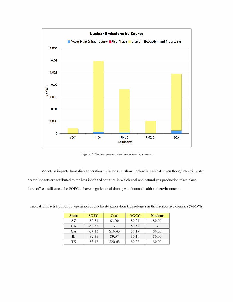
Figure 7: Nuclear power plant emissions by source.
Monetary impacts from direct operation emissions are shown below in Table 4. Even though electric water
heater impacts are attributed to the less inhabited counties in which coal and natural gas production takes place,
these offsets still cause the SOFC to have negative total damages to human health and environment.
Table 4: Impacts from direct operation of electricity generation technologies in their respective counties ($/MWh)
State SOFC Coal NGCC Nuclear AZ -$0.51 $3.00 $0.24 $0.00 CA -$0.32 - $0.59 - GA -$4.12 $16.43 $0.17 $0.00 IL -$2.56 $9.97 $0.19 $0.00 TX -$3.46 $20.63 $0.22 $0.00
Implications
These results show that SOFCs are most likely safe to use in urban areas. The emissions that would be
directly released into urban areas (during the use phase) are lower than those of other electricity generating
technologies. When water heater offsets (both natural gas and electric) from using the SOFCs for CHP are factored
in, SOFCs actually reduce emissions impacts.
In this way, computing the total life-cycle emissions for these technologies, rather than simply the use-
phase emissions, is revealing. While the SOFC has a lower use-phase emissions profile than coal-fired and NGCC
power plants, it looks less favorable than the zero-use-emissions nuclear plant. However, when the entire life-cycle
is considered (especially water heater offsets from using the SOFC for CHP), the SOFC has the lowest total
emission profile.
Breaking down the life-cycle emissions by source, as is done in Figures 3-7, shows the location of emission
hotspots. We see that electric water heater offsets (even when only 50% of SOFC adopters use electric water
heaters) have the largest contribution to life-cycle SOFC emissions. Consequently, these results are sensitive to
changes in regional electricity grid mixes. SOFCs produce greater emissions offsets in regions with coal-heavy
electric grids (such as Atlanta) and produce fewer offsets in regions with a greater percentage of electricity derived
from natural gas and/or nuclear power (such as San Francisco). In the future, if electricity production shifts to
‘cleaner’ fuels such as natural gas, nuclear, solar, or wind, SOFCs will look less favorable than they do with current
grid mixes.
There are relatively low emissions related to SOFC manufacturing and use. When water heater offsets are
not factored in, we can see from Figure 3 that life-cycle SOFC emissions are dominated by upstream processes
related to natural gas extraction, processing, and distribution. Because of recent increases in natural gas extraction
from shale rock, these emissions are likely to increase in the near future – during the same time frame in which we
may see residential SOFCs become commercially viable.
This study has shown that, aside from the benefit they provide for reducing water used in electricity
generation, fuel cells also provide the benefit of reducing pollutants through CHP offsets. By computing the total
monetary impact reduction that results from using SOFCs, cities and counties may find that there are additional
benefits to providing subsidies to homeowners for this new technology.
Uncertainty
There is uncertainty in the inventory results for the SOFC system LCA. First, 1 kWe SOFCs are not
currently manufactured at scale. The only systems currently in operation are test systems. If such SOFC systems
were to be mass-produced, there is no guarantee that they would be manufactured according to the method described
in Karakoussis et al 2000. Furthermore, the data from this study is 10 years old, and may no longer accurately reflect
up-to-date advances in SOFC technology. Additionally, Karakoussis et al 2000 assumes that all manufacturing uses
electricity generated from a natural gas combined cycle power plant. The study acknowledges that if actual grid
mixes were factored in (they use the example of the UK grid mix), the emissions profile for SOFC manufacturing
would be approximately 10% higher. Yet, judging from Figures 3 and 4, this increase would not significantly affect
overall results.
There is also uncertainty in the emissions profile of the SOFC system. For this study, average values are
taken from the literature. Yet, the source data is from much larger, commercial SOFC systems. It is possible that
large and small SOFC systems have different emissions outputs that are not linearly related. Also, the natural gas
water heater offsets are taken from average literature values. One of these values is from 1996, and may not reflect
current natural gas water heater technology.
For this study, inventory data for the centralized power plants is taken from GREET2, which derives its
results using averages from contemporary literature sources. Yet, for this study, we are ultimately interested in the
impacts of the next marginal power plant likely to be built. GREET2’s inventory data may not accurately represent
electricity-generating technologies likely to be deployed in the next few years. If electricity generating plants were
to reduce their emissions, SOFCs would not only look less favorable by comparison, but the offsets achieved by
decreasing the use of electric water heaters would also be reduced, thus causing life-cycle emissions for SOFCs to
increase.
Finally, the APEEP model calculates impacts from point and non-point sources separately. But, because of
the previously mentioned aggregation, all SOFC emissions are treated as coming from a non-point source, while all
emissions from the baseload power plants are treated as point sources. This aggregation ignores the fact that a SOFC
manufacturing plant, for example, would in actuality, be a point source when calculating impacts.
Future Work
This study is a small part of a larger work that explores factors that will increase the resilience of the
electricity supply to water shortages. Future work in this area will explore how varying levels of residential SOFC
adoption can reduce the need for water in regional electricity generation. However, it would be beneficial to have a
more comprehensive understanding of the total life-cycle impacts that result from SOFC use.
For proper impact assessment, the location of life-cycle processes is important. For this study, we were
only able to compute an impact assessment on the elements of the life-cycle with known locations (the use-phases of
the SOFCs and traditional electricity generating plants). However, for a more comprehensive assessment, the
locations of manufacturing as well as upstream processes for fuel feedstocks would need to be known. As the largest
(positive) contributor of life-cycle SOFC emissions is in upstream natural gas processing, locating the counties in
which these high-impact processes take place will be important in a more comprehensive assessment. Likewise,
discerning potential areas in which SOFC manufacturing would take place would also be important, especially
considering the amounts of SOx, NOx, and PM10 emitted during this process.
For the larger study of which this LCA is a part, we are interested in SOFC adoption offsetting the need for
new water-intensive traditional electricity generation plants to be built. Because SOFCs are a prospective
technology, it would be best to compare their emissions to those of electricity generation plants that are likely to be
installed within the same timeframe. Thus, a comparative LCA of SOFCs and these prospective power plants would
be appropriate for future work.
References
American Council for an Energy-Efficient Economy (ACEEE) (2011) Water Heating. from http://www.aceee.org/consumer/water-heating
DOE/NETL (2006) Emerging Issues for Fossil Energy and Water. EIA (2009) Residential Energy Consumption Survey. from http://www.eia.gov/consumption/residential/data/2009/ EIA (2012) State Electricity Profiles. from http://www.eia.gov/electricity/state/ EPA (1998) AP-42, Compilation of Air Pollutant Emission Factors. Chapter 1, Section 1.4. from
http://www.epa.gov/ttn/chief/ap42/ch01/final/c01s04.pdf FuelCell Energy (2010) DFC300 Model Catalogue. Hardikar, J., Mehta, R. Maharashtra’s largest thermal power plant to close all units by May 15. Daily News &
Analysis April 7, 2010. Retrieved from http://www.dnaindia.com/mumbai/report_maharashtras-largest-thermal-power-plant-to-close-all-units-by-may-15_1368282
Herron, S. and Williams, E. (under review) Geographic Cascading Experience Curves: Case Study of Residential
Fuel Cells in the U.S. Jowit, J., Espinoza, J. Heatwave shuts down nuclear power plants. The Observer July 29, 2006. Retrieved from
http://www.guardian.co.uk/environment/2006/jul/30/energy.weather Karakoussis, V. et al. (2000). Environmental Emission of SOFC and SPEC System Manufacture and Disposal.
Prepared for the ETSU. Muller, N. Z., R.O. Mendelsohn. (2009) "Efficient Pollution Regulation: Getting the Prices Right." American
Economic Review. 99 (5): 1714 - 1739. National Energy Technology Lab (2009) Impact of Drought on U.S. Steam Electric Power Plant Cooling Water
Intakes and Related Water Resource Management Issues. Osman, A.E. (2006). Life Cycle Optimization Model for Integrated Cogeneration and Energy System Applications
in Buildings. Prepared in partial fulfillment of the requirements for the degree of Doctor of Philosophy - University of Pittsburgh.
Pandit, A., Hyunju, J., Crittenden, J. C., French, S. P., Xu, M., Li. K. (under review) Sustainable Infrastructure and
Alternatives for urban Growth. Sovacool, B. K., Sovacool, K. E. (2009) Identifying future electricity-water tradeoffs in the United States. Energy
Policy 37, 2763-2773. Stambouli, A. and Traversa, E. (2002). SOFCs: a review of an environmentally clean and efficient source of energy.
Renewable and Sustainable Energy Reviews. 6(2002): 433-455. Sullivan, J. L.; Clark, C. E.; Han, J.; Wang, M. (2010) Life-Cycle Analysis Results of Geothermal Systems in
Comparison to Other Power Systems. Energy Systems Division, Argonne National Laboratory, Center for Transportation Research.
UTC Power (2008) The PureCell Model 400 Catalogue. Wang, M. (1999) The Greenhouse Gases, Regulated Emissions, and Energy Use in Transportation (GREET) Model:
Version 1.5. Argaonne National Laboratory, Center for Transportation Research