Page 1
MEF 55 © The MEF Forum 2016. Any reproduction of this document, or any portion thereof, shall contain the following statement: "Reproduced with permission of the MEF Forum." No user of this document is authorized to modify
any of the information contained herein.
Service Operations
Specification
MEF 55
Lifecycle Service Orchestration (LSO):
Reference Architecture and Framework
March 2016
Page 2
MEF 55 © The MEF Forum 2016. Any reproduction of this document, or any portion thereof, shall contain the following statement: "Reproduced with permission of the MEF Forum." No user of this document is authorized to modify
any of the information contained herein.
Disclaimer
The information in this publication is freely available for reproduction and use by any
recipient and is believed to be accurate as of its publication date. Such information is
subject to change without notice and the MEF Forum is not responsible for any errors.
The MEF does not assume responsibility to update or correct any information in this
publication. No representation or warranty, expressed or implied, is made by the MEF
concerning the completeness, accuracy, or applicability of any information contained
herein and no liability of any kind shall be assumed by the MEF as a result of reliance
upon such information.
The information contained herein is intended to be used without modification by the
recipient or user of this document. The MEF is not responsible or liable for any
modifications to this document made by any other party.
The receipt or any use of this document or its contents does not in any way create, by
implication or otherwise:
a) any express or implied license or right to or under any patent, copyright,
trademark or trade secret rights held or claimed by any MEF member company
which are or may be associated with the ideas, techniques, concepts or
expressions contained herein; nor
b) any warranty or representation that any MEF member companies will announce
any product(s) and/or service(s) related thereto, or if such announcements are
made, that such announced product(s) and/or service(s) embody any or all of the
ideas, technologies, or concepts contained herein; nor
c) any form of relationship between any MEF member companies and the recipient
or user of this document.
Implementation or use of specific Metro Ethernet standards or recommendations and
MEF specifications and guidelines will be voluntary, and no company shall be obliged to
implement them by virtue of participation in the MEF Forum. The MEF is a non-profit
international organization accelerating industry cooperation on Metro Ethernet
technology. The MEF does not, expressly or otherwise, endorse or promote any specific
products or services.
© The MEF Forum 2016. All Rights Reserved.
Page 3
LSO Reference Architecture and Framework
MEF 55
© The MEF Forum 2016. Any reproduction of this document, or any portion thereof, shall contain the
following statement: "Reproduced with permission of the MEF Forum." No user of this document is
authorized to modify any of the information contained herein.
Page ii
LSO Reference Architecture and Framework
Table of Contents
List of Figures ................................................................................................................................. v
List of Tables ................................................................................................................................. vi
1 List of Contributing Members .............................................................................................. vii
2 Abstract ................................................................................................................................... 1
3 Terminology and Acronyms ................................................................................................... 1
4 Scope ....................................................................................................................................... 6
5 Compliance Levels.................................................................................................................. 7
6 Introduction ............................................................................................................................. 8
6.1 Third Network Vision ...................................................................................................... 8
6.2 Lifecycle Service Orchestration ....................................................................................... 9
7 LSO Engineering Methodology ............................................................................................ 10
7.1 LSO Reference Architecture and Framework ................................................................ 11
7.2 Information Models ........................................................................................................ 11
7.3 Business Process Flows .................................................................................................. 12
7.4 Interface Profiles ............................................................................................................ 12
7.5 API Specifications and Data Models ............................................................................. 12
7.6 API Reference Implementations .................................................................................... 13
7.7 API Implementation Certification .................................................................................. 13
Page 4
LSO Reference Architecture and Framework
MEF 55
© The MEF Forum 2016. Any reproduction of this document, or any portion thereof, shall contain the
following statement: "Reproduced with permission of the MEF Forum." No user of this document is
authorized to modify any of the information contained herein.
Page iii
8 High Level Management Requirements ............................................................................... 14
8.1 Agile Product / Service Design ...................................................................................... 14
8.2 Order Fulfillment and Service Control........................................................................... 14
8.2.1 Order Fulfillment Orchestration ............................................................................. 15
8.2.2 Service Configuration and Activation Orchestration .............................................. 16
8.2.3 Service Control Orchestration................................................................................. 18
8.2.4 Service Delivery Orchestration ............................................................................... 19
8.3 Service Testing Orchestration ........................................................................................ 20
8.4 Service Problem Management for LSO ......................................................................... 21
8.5 Service Quality Management for LSO ........................................................................... 22
8.6 Billing and Usage Measurements for LSO .................................................................... 23
8.7 Security Management for LSO ...................................................................................... 23
8.8 Analytics for LSO .......................................................................................................... 24
8.9 Policy-based Management for LSO ............................................................................... 25
8.10 Customer Management for LSO ................................................................................. 25
8.11 Partner Management for LSO ..................................................................................... 26
9 LSO Reference Architecture ................................................................................................. 27
9.1 Definition of LSO Functional Management Entities ..................................................... 27
9.1.1 Examples of SDO Architectural Elements within Infrastructure Control and
Management .......................................................................................................................... 28
9.2 Definition of Management Interface Reference Points .................................................. 29
10 Operational Threads for LSO................................................................................................ 31
10.1 Designing and Launching a New Product Offering ................................................... 31
10.2 Partners On-boarding .................................................................................................. 31
Page 5
LSO Reference Architecture and Framework
MEF 55
© The MEF Forum 2016. Any reproduction of this document, or any portion thereof, shall contain the
following statement: "Reproduced with permission of the MEF Forum." No user of this document is
authorized to modify any of the information contained herein.
Page iv
10.3 Product Ordering and Service Activation Orchestration ............................................ 32
10.4 Controlling a Service .................................................................................................. 32
10.5 Customer Viewing of Performance and Fault Reports and Metrics ........................... 32
10.6 Placing and Tracking Trouble Reports ....................................................................... 32
10.7 Assessing Service Quality Based on SLS................................................................... 33
10.8 Collection and Reporting of Billing and Usage .......................................................... 33
10.9 Securing Management and Control Mechanisms ....................................................... 33
10.10 Providing Connectivity Services for Cloud ................................................................ 33
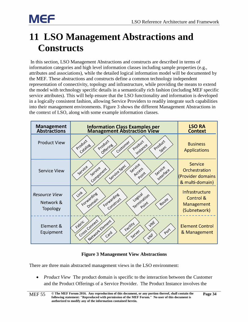
11 LSO Management Abstractions and Constructs ................................................................... 34
11.1 Product View Abstractions ......................................................................................... 36
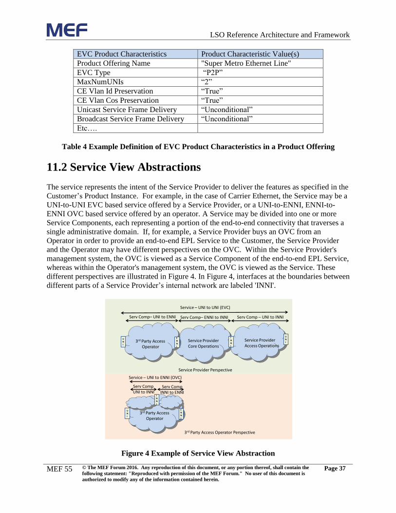
11.2 Service View Abstractions ......................................................................................... 37
11.3 Resource View Abstractions ...................................................................................... 38
11.3.1 Network and Topology View Abstractions ............................................................ 38
11.3.2 Element and Equipment View Abstractions ........................................................... 38
12 References ............................................................................................................................. 40
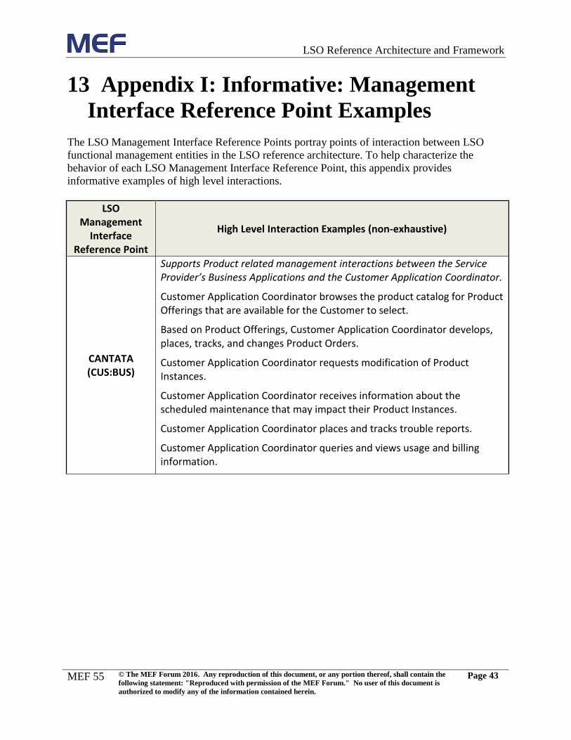
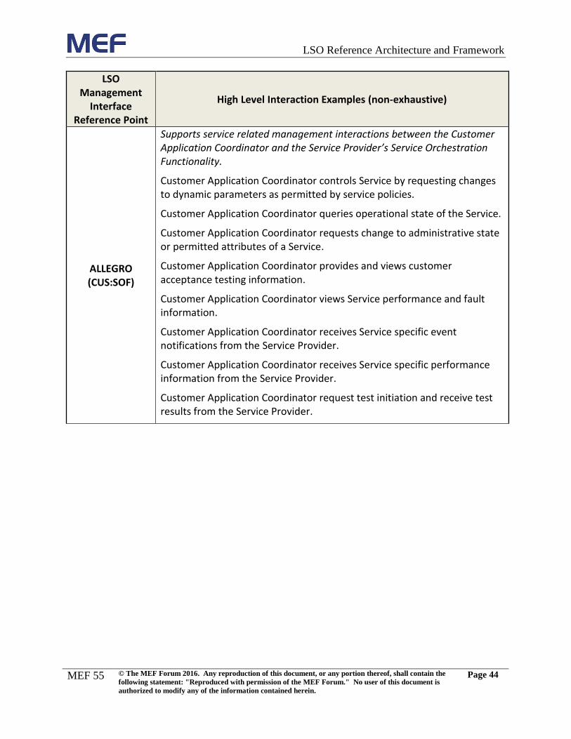
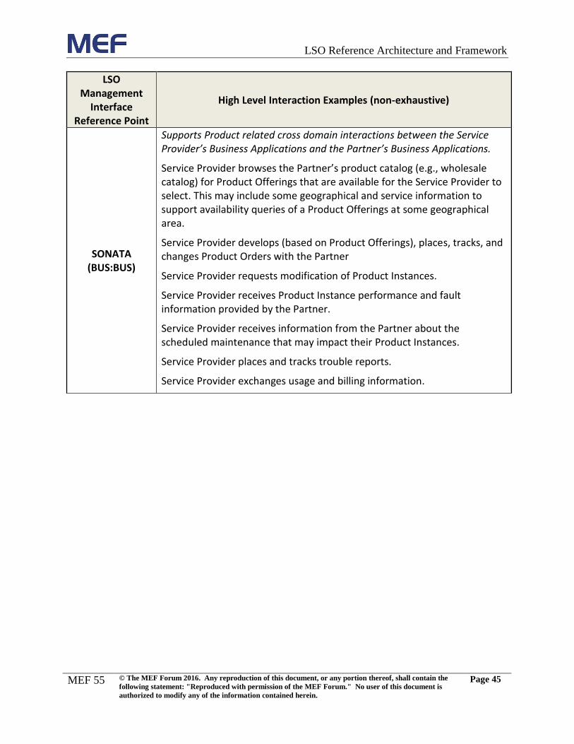
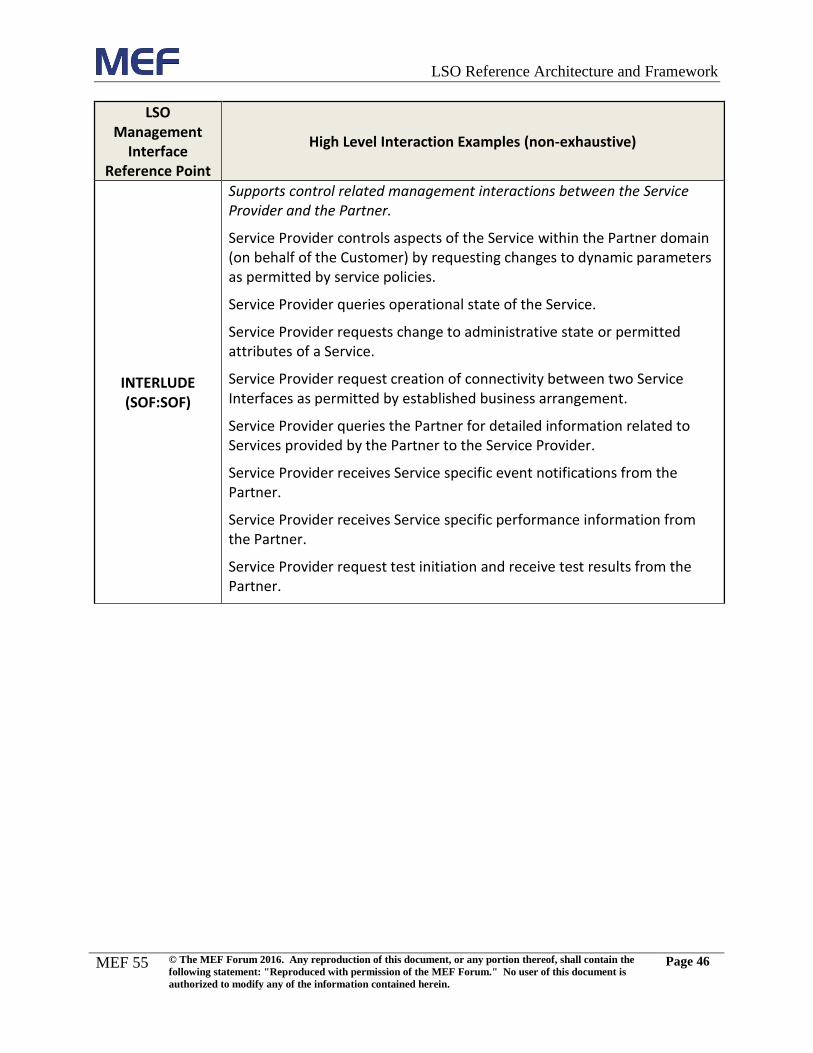
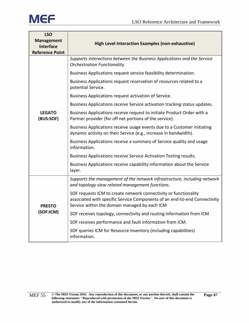
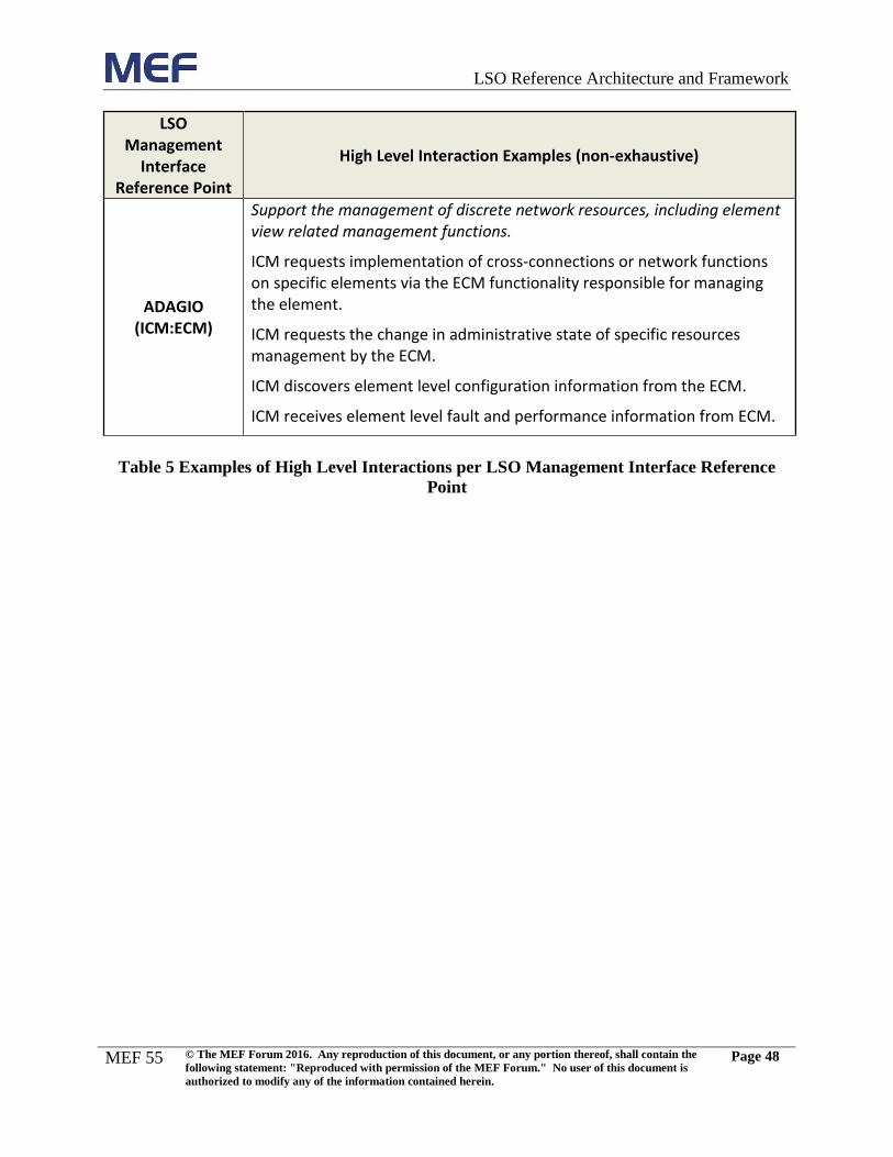
13 Appendix I: Informative: Management Interface Reference Point Examples ...................... 43
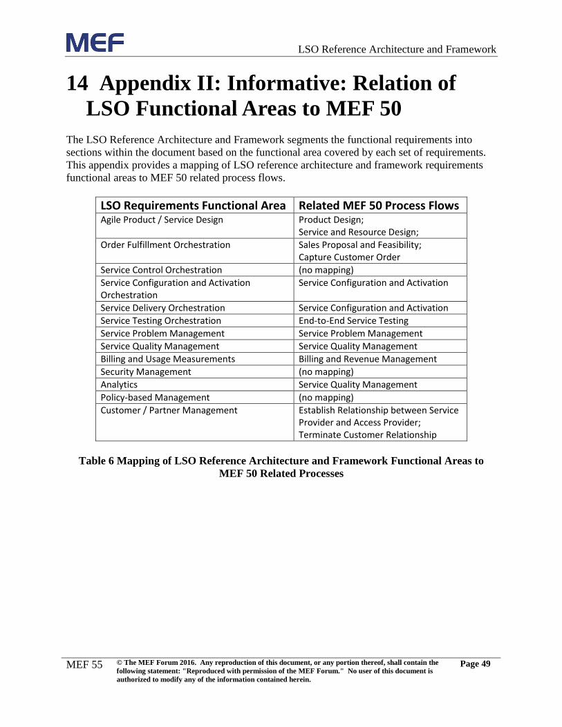
14 Appendix II: Informative: Relation of LSO Functional Areas to MEF 50 ........................... 49
Page 6
LSO Reference Architecture and Framework
MEF 55
© The MEF Forum 2016. Any reproduction of this document, or any portion thereof, shall contain the
following statement: "Reproduced with permission of the MEF Forum." No user of this document is
authorized to modify any of the information contained herein.
Page v
List of Figures
Figure 1 LSO Engineering Methodology ..................................................................................... 10
Figure 2 LSO Reference Architecture .......................................................................................... 27
Figure 3 Management View Abstractions .................................................................................... 34
Figure 4 Example of Service View Abstraction ........................................................................... 37
Page 7
LSO Reference Architecture and Framework
MEF 55
© The MEF Forum 2016. Any reproduction of this document, or any portion thereof, shall contain the
following statement: "Reproduced with permission of the MEF Forum." No user of this document is
authorized to modify any of the information contained herein.
Page vi
List of Tables
Table 1 Contributing Member ...................................................................................................... vii
Table 2 Terminology and Acronyms .............................................................................................. 6
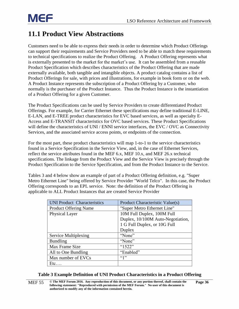
Table 3 Example Definition of UNI Product Characteristics in a Product Offering .................... 36
Table 4 Example Definition of EVC Product Characteristics in a Product Offering ................... 37
Table 5 Examples of High Level Interactions per LSO Management Interface Reference Point 48
Table 6 Mapping of LSO Reference Architecture and Framework Functional Areas to MEF 50
Related Processes .......................................................................................................................... 49
Page 8
LSO Reference Architecture and Framework
MEF 55
© The MEF Forum 2016. Any reproduction of this document, or any portion thereof, shall contain the
following statement: "Reproduced with permission of the MEF Forum." No user of this document is
authorized to modify any of the information contained herein.
Page vii
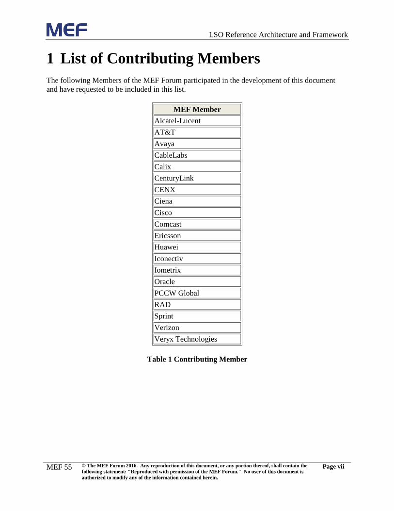
1 List of Contributing Members
The following Members of the MEF Forum participated in the development of this document
and have requested to be included in this list.
MEF Member
Alcatel-Lucent
AT&T
Avaya
CableLabs
Calix
CenturyLink
CENX
Ciena
Cisco
Comcast
Ericsson
Huawei
Iconectiv
Iometrix
Oracle
PCCW Global
RAD
Sprint
Verizon
Veryx Technologies
Table 1 Contributing Member
Page 9
LSO Reference Architecture and Framework
MEF 55
© The MEF Forum 2016. Any reproduction of this document, or any portion thereof, shall contain the
following statement: "Reproduced with permission of the MEF Forum." No user of this document is
authorized to modify any of the information contained herein.
Page 1
2 Abstract
LSO is an agile approach to streamlining and automating the service lifecycle in a sustainable
fashion for coordinated management and control across all network domains responsible for
delivering an end-to-end Connectivity Service (e.g., Carrier Ethernet, IP VPN, MPLS, etc.). This
document describes a Reference Architecture and Framework for orchestrating the service
lifecycle. It includes a set of functional management entities that enable cooperative service
lifecycle orchestration for Third Network Connectivity Services. The framework also provides
high level functional requirements and outlines high level operational threads describing
orchestrated Connectivity Service behavior as well as interactions among management and
control entities. The Management Interface Reference Points that characterize interactions
between LSO functional management entities are identified in the reference architecture. These
Management Interface Reference Points are described such that they can be realized by Interface
Profiles and further by APIs, which can be used to enable automated and orchestrated
Connectivity Services.
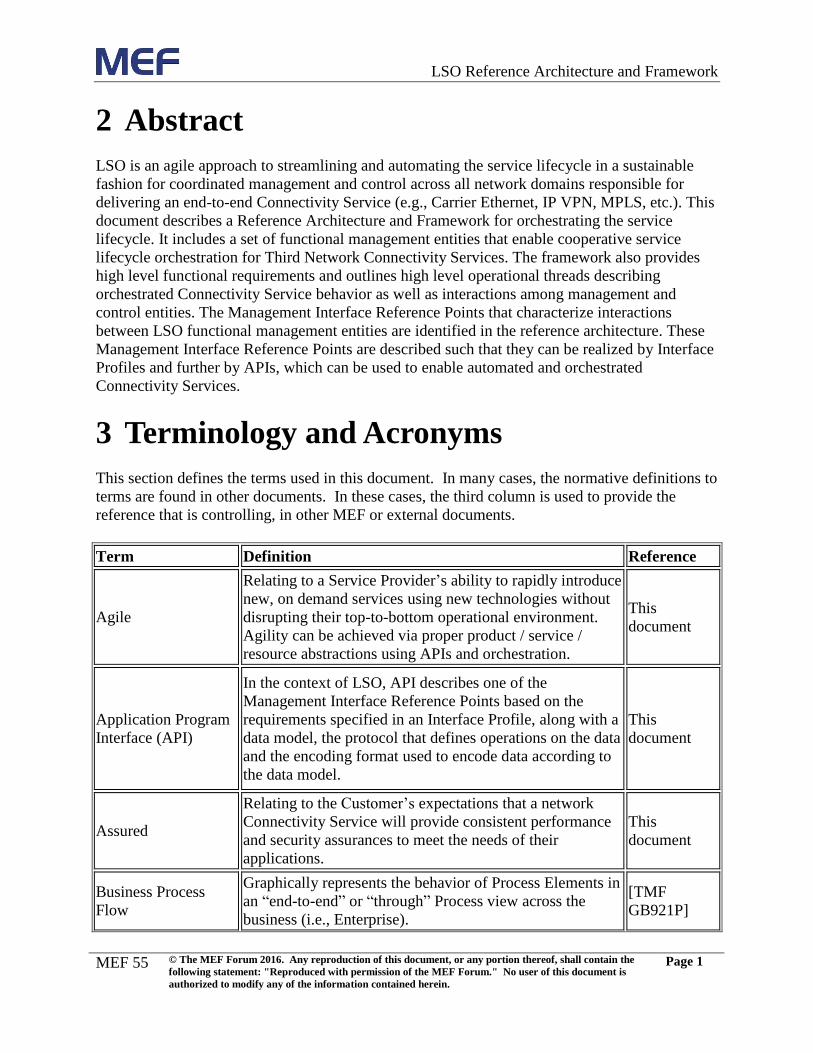
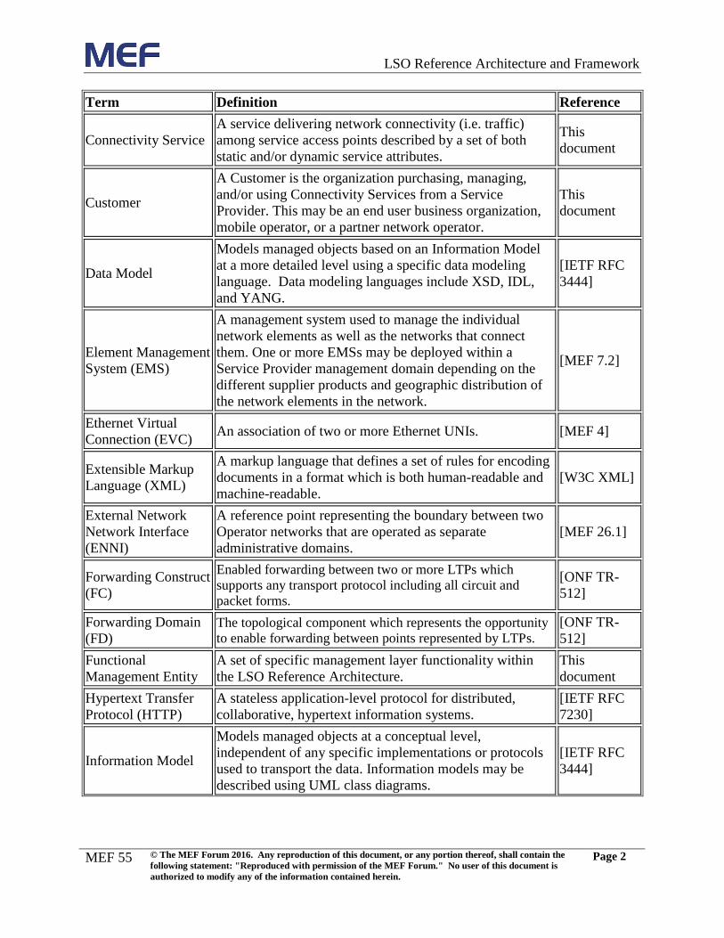
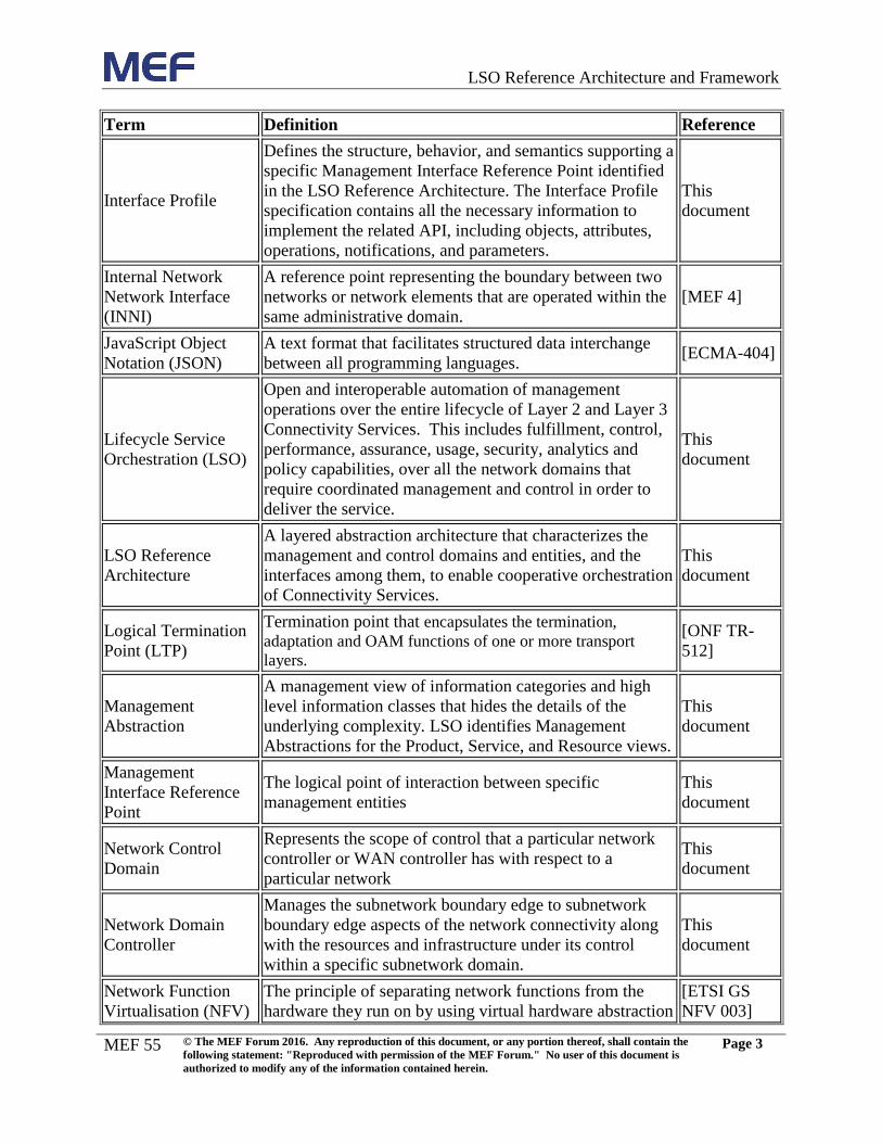
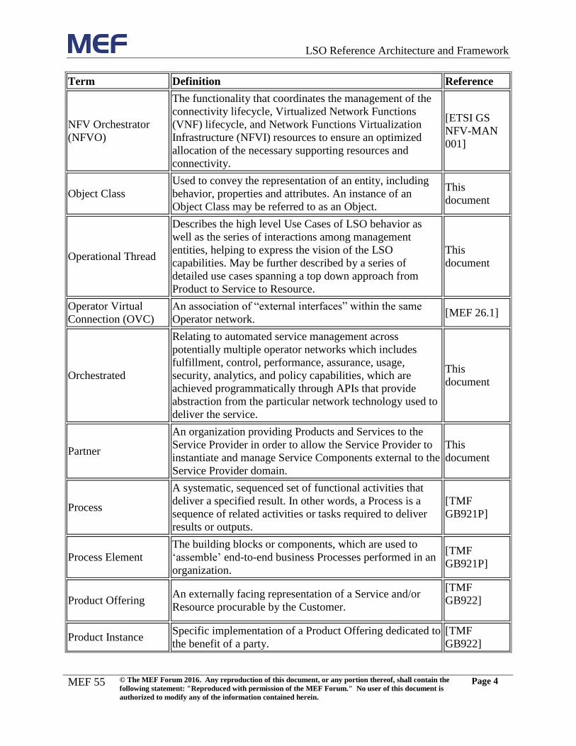
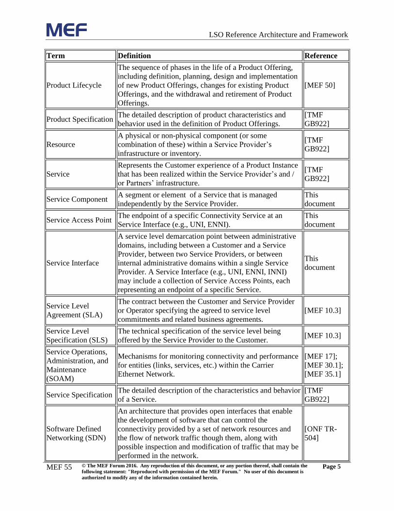
3 Terminology and Acronyms
This section defines the terms used in this document. In many cases, the normative definitions to
terms are found in other documents. In these cases, the third column is used to provide the
reference that is controlling, in other MEF or external documents.
Term Definition Reference
Agile
Relating to a Service Provider’s ability to rapidly introduce
new, on demand services using new technologies without
disrupting their top-to-bottom operational environment.
Agility can be achieved via proper product / service /
resource abstractions using APIs and orchestration.
This
document
Application Program
Interface (API)
In the context of LSO, API describes one of the
Management Interface Reference Points based on the
requirements specified in an Interface Profile, along with a
data model, the protocol that defines operations on the data
and the encoding format used to encode data according to
the data model.
This
document
Assured
Relating to the Customer’s expectations that a network
Connectivity Service will provide consistent performance
and security assurances to meet the needs of their
applications.
This
document
Business Process
Flow
Graphically represents the behavior of Process Elements in
an “end-to-end” or “through” Process view across the
business (i.e., Enterprise).
[TMF
GB921P]
Page 10
LSO Reference Architecture and Framework
MEF 55
© The MEF Forum 2016. Any reproduction of this document, or any portion thereof, shall contain the
following statement: "Reproduced with permission of the MEF Forum." No user of this document is
authorized to modify any of the information contained herein.
Page 2
Term Definition Reference
Connectivity Service
A service delivering network connectivity (i.e. traffic)
among service access points described by a set of both
static and/or dynamic service attributes.
This
document
Customer
A Customer is the organization purchasing, managing,
and/or using Connectivity Services from a Service
Provider. This may be an end user business organization,
mobile operator, or a partner network operator.
This
document
Data Model
Models managed objects based on an Information Model
at a more detailed level using a specific data modeling
language. Data modeling languages include XSD, IDL,
and YANG.
[IETF RFC
3444]
Element Management
System (EMS)
A management system used to manage the individual
network elements as well as the networks that connect
them. One or more EMSs may be deployed within a
Service Provider management domain depending on the
different supplier products and geographic distribution of
the network elements in the network.
[MEF 7.2]
Ethernet Virtual
Connection (EVC) An association of two or more Ethernet UNIs. [MEF 4]
Extensible Markup
Language (XML)
A markup language that defines a set of rules for encoding
documents in a format which is both human-readable and
machine-readable.
[W3C XML]
External Network
Network Interface
(ENNI)
A reference point representing the boundary between two
Operator networks that are operated as separate
administrative domains.
[MEF 26.1]
Forwarding Construct
(FC)
Enabled forwarding between two or more LTPs which
supports any transport protocol including all circuit and
packet forms.
[ONF TR-
512]
Forwarding Domain
(FD) The topological component which represents the opportunity
to enable forwarding between points represented by LTPs. [ONF TR-
512]
Functional
Management Entity
A set of specific management layer functionality within
the LSO Reference Architecture.
This
document
Hypertext Transfer
Protocol (HTTP)
A stateless application-level protocol for distributed,
collaborative, hypertext information systems.
[IETF RFC
7230]
Information Model
Models managed objects at a conceptual level,
independent of any specific implementations or protocols
used to transport the data. Information models may be
described using UML class diagrams.
[IETF RFC
3444]
Page 11
LSO Reference Architecture and Framework
MEF 55
© The MEF Forum 2016. Any reproduction of this document, or any portion thereof, shall contain the
following statement: "Reproduced with permission of the MEF Forum." No user of this document is
authorized to modify any of the information contained herein.
Page 3
Term Definition Reference
Interface Profile
Defines the structure, behavior, and semantics supporting a
specific Management Interface Reference Point identified
in the LSO Reference Architecture. The Interface Profile
specification contains all the necessary information to
implement the related API, including objects, attributes,
operations, notifications, and parameters.
This
document
Internal Network
Network Interface
(INNI)
A reference point representing the boundary between two
networks or network elements that are operated within the
same administrative domain.
[MEF 4]
JavaScript Object
Notation (JSON)
A text format that facilitates structured data interchange
between all programming languages. [ECMA-404]
Lifecycle Service
Orchestration (LSO)
Open and interoperable automation of management
operations over the entire lifecycle of Layer 2 and Layer 3
Connectivity Services. This includes fulfillment, control,
performance, assurance, usage, security, analytics and
policy capabilities, over all the network domains that
require coordinated management and control in order to
deliver the service.
This
document
LSO Reference
Architecture
A layered abstraction architecture that characterizes the
management and control domains and entities, and the
interfaces among them, to enable cooperative orchestration
of Connectivity Services.
This
document
Logical Termination
Point (LTP)
Termination point that encapsulates the termination,
adaptation and OAM functions of one or more transport
layers.
[ONF TR-
512]
Management
Abstraction
A management view of information categories and high
level information classes that hides the details of the
underlying complexity. LSO identifies Management
Abstractions for the Product, Service, and Resource views.
This
document
Management
Interface Reference
Point
The logical point of interaction between specific
management entities
This
document
Network Control
Domain
Represents the scope of control that a particular network
controller or WAN controller has with respect to a
particular network
This
document
Network Domain
Controller
Manages the subnetwork boundary edge to subnetwork
boundary edge aspects of the network connectivity along
with the resources and infrastructure under its control
within a specific subnetwork domain.
This
document
Network Function
Virtualisation (NFV)
The principle of separating network functions from the
hardware they run on by using virtual hardware abstraction
[ETSI GS
NFV 003]
Page 12
LSO Reference Architecture and Framework
MEF 55
© The MEF Forum 2016. Any reproduction of this document, or any portion thereof, shall contain the
following statement: "Reproduced with permission of the MEF Forum." No user of this document is
authorized to modify any of the information contained herein.
Page 4
Term Definition Reference
NFV Orchestrator
(NFVO)
The functionality that coordinates the management of the
connectivity lifecycle, Virtualized Network Functions
(VNF) lifecycle, and Network Functions Virtualization
Infrastructure (NFVI) resources to ensure an optimized
allocation of the necessary supporting resources and
connectivity.
[ETSI GS
NFV-MAN
001]
Object Class
Used to convey the representation of an entity, including
behavior, properties and attributes. An instance of an
Object Class may be referred to as an Object.
This
document
Operational Thread
Describes the high level Use Cases of LSO behavior as
well as the series of interactions among management
entities, helping to express the vision of the LSO
capabilities. May be further described by a series of
detailed use cases spanning a top down approach from
Product to Service to Resource.
This
document
Operator Virtual
Connection (OVC)
An association of “external interfaces” within the same
Operator network. [MEF 26.1]
Orchestrated
Relating to automated service management across
potentially multiple operator networks which includes
fulfillment, control, performance, assurance, usage,
security, analytics, and policy capabilities, which are
achieved programmatically through APIs that provide
abstraction from the particular network technology used to
deliver the service.
This
document
Partner
An organization providing Products and Services to the
Service Provider in order to allow the Service Provider to
instantiate and manage Service Components external to the
Service Provider domain.
This
document
Process
A systematic, sequenced set of functional activities that
deliver a specified result. In other words, a Process is a
sequence of related activities or tasks required to deliver
results or outputs.
[TMF
GB921P]
Process Element
The building blocks or components, which are used to
‘assemble’ end-to-end business Processes performed in an
organization.
[TMF
GB921P]
Product Offering An externally facing representation of a Service and/or
Resource procurable by the Customer.
[TMF
GB922]
Product Instance Specific implementation of a Product Offering dedicated to
the benefit of a party.
[TMF
GB922]
Page 13
LSO Reference Architecture and Framework
MEF 55
© The MEF Forum 2016. Any reproduction of this document, or any portion thereof, shall contain the
following statement: "Reproduced with permission of the MEF Forum." No user of this document is
authorized to modify any of the information contained herein.
Page 5
Term Definition Reference
Product Lifecycle
The sequence of phases in the life of a Product Offering,
including definition, planning, design and implementation
of new Product Offerings, changes for existing Product
Offerings, and the withdrawal and retirement of Product
Offerings.
[MEF 50]
Product Specification The detailed description of product characteristics and
behavior used in the definition of Product Offerings.
[TMF
GB922]
Resource
A physical or non-physical component (or some
combination of these) within a Service Provider’s
infrastructure or inventory.
[TMF
GB922]
Service
Represents the Customer experience of a Product Instance
that has been realized within the Service Provider’s and /
or Partners’ infrastructure.
[TMF
GB922]
Service Component A segment or element of a Service that is managed
independently by the Service Provider.
This
document
Service Access Point The endpoint of a specific Connectivity Service at an
Service Interface (e.g., UNI, ENNI).
This
document
Service Interface
A service level demarcation point between administrative
domains, including between a Customer and a Service
Provider, between two Service Providers, or between
internal administrative domains within a single Service
Provider. A Service Interface (e.g., UNI, ENNI, INNI)
may include a collection of Service Access Points, each
representing an endpoint of a specific Service.
This
document
Service Level
Agreement (SLA)
The contract between the Customer and Service Provider
or Operator specifying the agreed to service level
commitments and related business agreements.
[MEF 10.3]
Service Level
Specification (SLS)
The technical specification of the service level being
offered by the Service Provider to the Customer. [MEF 10.3]
Service Operations,
Administration, and
Maintenance
(SOAM)
Mechanisms for monitoring connectivity and performance
for entities (links, services, etc.) within the Carrier
Ethernet Network.
[MEF 17];
[MEF 30.1];
[MEF 35.1]
Service Specification The detailed description of the characteristics and behavior
of a Service.
[TMF
GB922]
Software Defined
Networking (SDN)
An architecture that provides open interfaces that enable
the development of software that can control the
connectivity provided by a set of network resources and
the flow of network traffic though them, along with
possible inspection and modification of traffic that may be
performed in the network.
[ONF TR-
504]
Page 14
LSO Reference Architecture and Framework
MEF 55
© The MEF Forum 2016. Any reproduction of this document, or any portion thereof, shall contain the
following statement: "Reproduced with permission of the MEF Forum." No user of this document is
authorized to modify any of the information contained herein.
Page 6
Term Definition Reference
SDN Controller
Translates SDN applications’ requirements and exerts
more granular control over network elements, while
providing relevant information up to SDN applications.
[ONF TR-
504]
Unified Modeling
Language (UML)
A general-purpose, developmental, modeling language in
the field of software engineering that is intended to provide
a standard way to visualize the design of a system.
[OMG UML]
Use Case
In UML, a Use Case represents one particular type of a
system’s behavior based on stimuli from an external
source (i.e., an actor). A system may have several Use
Cases that define all its behavior.
[OMG UML]
User Network
Interface (UNI)
The physical demarcation point between the responsibility
of the Service Provider and the responsibility of the
Customer.
[MEF 11]
Virtual Network
Element (VNE)
An abstraction representing a set of network functions
providing network element capabilities implemented in a
virtualized environment.
This
document
Table 2 Terminology and Acronyms
4 Scope
The purpose of this document is to define a reference architecture that describes the functional
management entities needed to support LSO, and the Management Interface Reference Points
between them. LSO provides open and interoperable automation of management operations over
the entire lifecycle of Layer 2 and Layer 3 Connectivity Services. This includes design,
fulfillment, control, testing, problem management, quality management, billing & usage,
security, analytics and policy capabilities, over all the network domains that require coordinated
management and control in order to deliver the service. The reference architecture characterizes
the management and control domains and entities that enable cooperative LSO capabilities for
Connectivity Services. The LSO architecture and framework enables automated management
and control of end-to-end Connectivity Services that span multiple provider domains. For
example, a Service Provider may extend its footprint by using LSO to interact with potentially
several Operators to manage and control the access portions of end-to-end services.
The framework also outlines high level operational threads providing business rationale and
describing orchestrated Connectivity Service behavior as well as interactions among
management and control entities. This document describes the essential LSO capabilities for
Connectivity Services that need to be supported by the common product, service, and resource
abstractions and constructs. Such constructs will drive the information and data models that
enable the definition of open and interoperable APIs supporting LSO functionality (including
virtualized functions, e.g., SDN and NFV). From a services perspective, this framework is
intended to support current MEF services; however the framework is also extensible, providing
Page 15
LSO Reference Architecture and Framework
MEF 55
© The MEF Forum 2016. Any reproduction of this document, or any portion thereof, shall contain the
following statement: "Reproduced with permission of the MEF Forum." No user of this document is
authorized to modify any of the information contained herein.
Page 7
the flexibility to handle generic Connectivity Services as well by defining Connectivity Services
management constructs. The reference architecture work will also be cross referenced with the
efforts of other Standards Development Organizations (SDOs) and open-source projects (e.g.,
ONF, ETSI NFV, IEEE, ITU-T, IETF, TMF, OPNFV, ODL, OpenStack, etc.).
This framework also describes the engineering approach being followed to generate re-usable
engineering specifications and artifacts capturing the LSO requirements, capabilities,
functionality, behavior, processes, information, interfaces and APIs supporting management and
control of Connectivity Services.
5 Compliance Levels
The requirements in this document that apply to the high level functionality are specified in
Section 8. Items that are REQUIRED (contain the words MUST or MUST NOT) will be labeled
as [Rx]. Items that are RECOMMENDED (contain the words SHOULD or SHOULD NOT)
will be labeled as [Dx]. Items that are OPTIONAL (contain the words MAY or OPTIONAL)
will be labeled as [Ox].
The key words “MUST”, “MUST NOT”, “REQUIRED”, “SHALL”, “SHALL NOT”,
“SHOULD”, “SHOULD NOT”, “RECOMMENDED”, “MAY”, and “OPTIONAL” in this
document are to be interpreted as described in RFC 2119. All key words use upper case, bold
text to distinguish them from other uses of the words. Any use of these key words (e.g., may and
optional) without [Rx], [Dx] or [Ox] is not normative.
Page 16
LSO Reference Architecture and Framework
MEF 55
© The MEF Forum 2016. Any reproduction of this document, or any portion thereof, shall contain the
following statement: "Reproduced with permission of the MEF Forum." No user of this document is
authorized to modify any of the information contained herein.
Page 8
6 Introduction
LSO provides orchestration capabilities for the open and interoperable management and control
of Third Network Connectivity Services [MEF ThirdNetwork]. The LSO Reference Architecture
characterizes the management and control domains and entities that enable cooperative LSO
capabilities. This architecture also outlines high level operational threads describing orchestrated
Connectivity Service behavior as well as interactions among management entities. LSO
overcomes existing complexity by defining product, service, and resource abstractions that hide
the complexity of underlying technologies and network layers from the applications and users of
the services.
In this document, Section 7 discusses the LSO engineering methodology. The high level
functional requirements for LSO functional management entities are provided in Section 8.
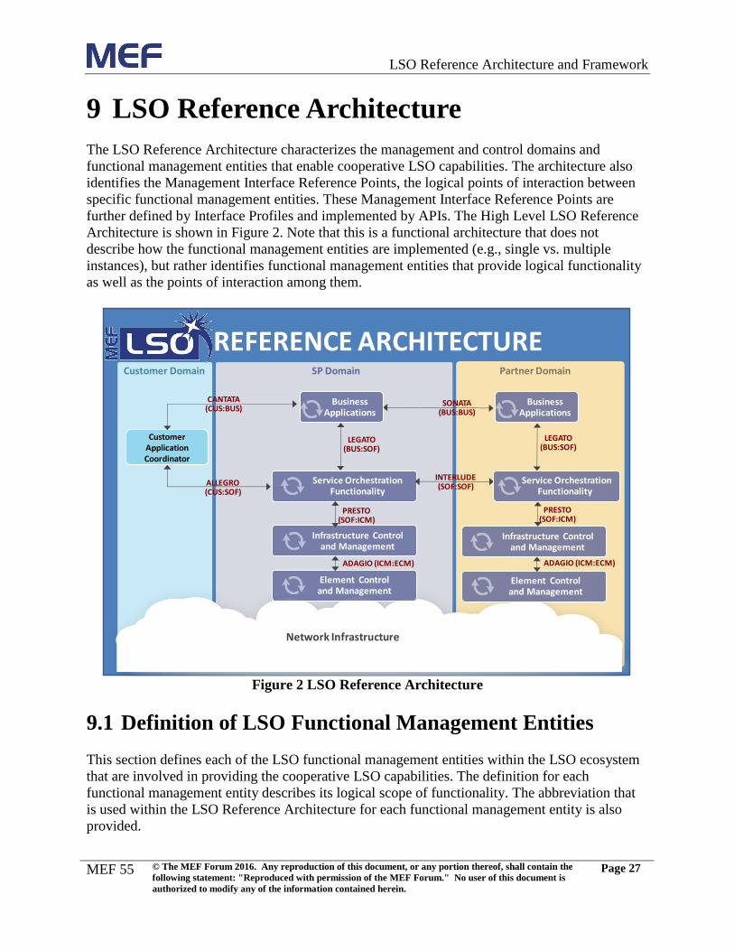
Section 9 provides the LSO Reference Architecture that characterizes the management and
control domains and functional management entities that enable cooperative LSO capabilities.
High level Operational Threads describing the use cases for LSO behavior are identified in
Section 10. LSO Management Abstractions and constructs are described in Section 11.
References may be found in Section 12. Section 13 provides an informative appendix with
examples of high level interactions per LSO management interface reference point. Lastly,
Section 14 is an appendix providing a mapping of LSO reference architecture and framework
functional areas to MEF 50 related processes.
6.1 Third Network Vision
The MEF Forum vision for the evolution and transformation of network Connectivity Services
and the networks used to deliver them is referred to as the “Third Network” [MEF
ThirdNetwork]. The Third Network combines the on-demand agility and ubiquity of the Internet
with the performance and security assurances like that of Carrier Ethernet 2.0 (CE 2.0). The
Third Network will enable services between not only service access points residing on physical
ports, such as Ethernet ports, but also service access points residing on interfaces running on a
blade server in the cloud to connect to Virtual Machines (VMs) or Virtual Network Functions
(VNFs).
The Third Network vision is based on Network as a Service (NaaS) principles which make the
network appear as a user’s own virtual network, and enables the user to dynamically and on-
demand, create, modify and delete services via Customer web portals or software applications.
This is analogous to cloud-based services, such as infrastructure as a service (IaaS), where users
can dynamically create, modify or delete compute and storage resources.
The MEF Forum will achieve this vision by building upon its successful CE 2.0 foundation by
defining requirements for LSO [MEF LSO] and APIs in support of service ordering, fulfillment,
performance, usage, analytics and security across multi-operator networks. This approach
overcomes existing constraints by defining service abstractions that hide the complexity of
Page 17
LSO Reference Architecture and Framework
MEF 55
© The MEF Forum 2016. Any reproduction of this document, or any portion thereof, shall contain the
following statement: "Reproduced with permission of the MEF Forum." No user of this document is
authorized to modify any of the information contained herein.
Page 9
underlying technologies and network layers from the applications and users of the services, while
providing sufficient management and control capabilities.
In summary, the goal of the Third Network, based on NaaS principles, is to enable agile
networks that deliver assured Connectivity Services orchestrated across network domains.
6.2 Lifecycle Service Orchestration
Since Connectivity Services in the Third Network are agile, assured, and orchestrated, they rely
on coordinated orchestration of distributed capabilities across potentially many internal networks
and many network operators to enable end-to-end management. Such orchestration is executed
for the entire Connectivity Service lifecycle where each functional area of the lifecycle is further
streamlined and automated, from Product Offering definition through service fulfillment, control,
assurance, and billing [MEF 50]. For example, the fulfillment phases of the service lifecycle are
focused on automating the inter-provider business interactions and interfaces for the buyer-seller
process, including the product catalog, order, service location, and service qualification. Each of
these phases is based on the Product Offering defined by the selling carrier. Since the Product
Offering is fully defined in the product catalog, a model-driven approach is used to execute the
subsequent stages of the service lifecycle, including pre-order, order, and service orchestration.
By using a model-driven approach along with abstractions representing products, services, and
resources, LSO ensures an agile approach to streamlining and automating the entire service
lifecycle in a sustainable fashion.
In LSO, Connectivity Services are orchestrated by Service Providers across all internal and
external network domains from one or more network operators. These network domains may be
operated by communications Service Providers, data center operators, enterprises, wireless
network operators, virtual network operators, or content providers. LSO encompasses all
network domains that require coordinated end-to-end management and control to deliver
Connectivity Services. Within each provider domain, the network infrastructure may be
implemented with traditional WAN technologies, as well as NFV and/or SDN. LSO capabilities
not only dramatically decrease the time to establish and modify the characteristics of the
Connectivity Service, but also assure the overall service quality and security for these services.
Page 18
LSO Reference Architecture and Framework
MEF 55
© The MEF Forum 2016. Any reproduction of this document, or any portion thereof, shall contain the
following statement: "Reproduced with permission of the MEF Forum." No user of this document is
authorized to modify any of the information contained herein.
Page 10
7 LSO Engineering Methodology
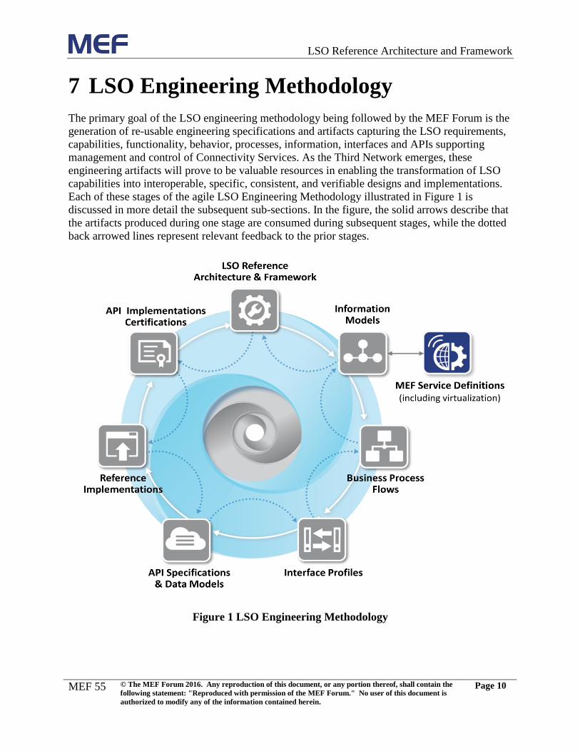
The primary goal of the LSO engineering methodology being followed by the MEF Forum is the
generation of re-usable engineering specifications and artifacts capturing the LSO requirements,
capabilities, functionality, behavior, processes, information, interfaces and APIs supporting
management and control of Connectivity Services. As the Third Network emerges, these
engineering artifacts will prove to be valuable resources in enabling the transformation of LSO
capabilities into interoperable, specific, consistent, and verifiable designs and implementations.
Each of these stages of the agile LSO Engineering Methodology illustrated in Figure 1 is
discussed in more detail the subsequent sub-sections. In the figure, the solid arrows describe that
the artifacts produced during one stage are consumed during subsequent stages, while the dotted
back arrowed lines represent relevant feedback to the prior stages.
Figure 1 LSO Engineering Methodology
Page 19
LSO Reference Architecture and Framework
MEF 55
© The MEF Forum 2016. Any reproduction of this document, or any portion thereof, shall contain the
following statement: "Reproduced with permission of the MEF Forum." No user of this document is
authorized to modify any of the information contained herein.
Page 11
7.1 LSO Reference Architecture and Framework
The LSO Reference Architecture and Framework, specified in this document, provides a layered
architecture that characterizes the management and control domains and entities that enable
cooperative LSO capabilities for Connectivity Services. The framework also describes the high
level management requirements and outlines high level operational threads. Operational threads
describe orchestrated Connectivity Service behavior as well as interactions among management
entities spanning the Customer, Service Provider, and partner provider management domains,
expressing the vision of the MEF LSO capabilities. Within the LSO Reference Architecture, a
Management Interface Reference Point is the logical point of interaction between specific
management entities. The Management Interface Reference Points that characterize interactions
between LSO functional management entities are identified in the reference architecture. These
Management Interface Reference Points are further defined by Interface Profiles and
implemented by APIs and Reference Implementations that realize automated and orchestrated
Connectivity Services. An Interface Reference Point may be described by a number of Interface
Profiles, each addressing a specific functional scope. Artifacts from the LSO Reference
Architecture and Framework are used by the subsequent stages in the methodology. Lessons
learned from API certification may be used to update the LSO Reference Architecture.
As a specification the LSO Reference Architecture and Framework:
Describes the LSO engineering methodology (Section 7);
Provides high level requirements associated with LSO functional areas (Section 8);
Defines the LSO reference architecture (Section 9);
Outlines operational threads for LSO (Section 10); and
Identifies the LSO Management Abstractions and constructs (Section 11).
7.2 Information Models
Information Models define managed objects at a conceptual level, independent of any specific
implementations or protocols used to transport the data. The shared common Information Models
for LSO supporting Connectivity Services include the service attributes defined in MEF
Specifications defining a common set of consistent managed object definitions for managing the
service lifecycle. These common management and control information models support
management of Products, Services, and Resources. This helps ensure that management and
control functionality and information shared among Customer relationship management, service
management, resource management, and supplier / partner management functions, as well as
orchestrators, infrastructure managers, controllers (e.g., Network Domain Controllers, SDN
controllers, etc.), and Network Elements (NEs) are provided in a logically consistent fashion
allowing network operators to readily integrate such capabilities into their Connectivity Service
management and control environment. The MEF Forum defines management information
models supporting LSO, that describe the information associated with the generalized
management interactions using protocol neutral Unified Modeling Language (UML). Artifacts
from the information models are used by the subsequent stages in the methodology, including the
Page 20
LSO Reference Architecture and Framework
MEF 55
© The MEF Forum 2016. Any reproduction of this document, or any portion thereof, shall contain the
following statement: "Reproduced with permission of the MEF Forum." No user of this document is
authorized to modify any of the information contained herein.
Page 12
definition of Interface Profiles. Lessons learned from information models may be used to update
the Management Abstractions in LSO Reference Architecture.
7.3 Business Process Flows
The details of the high level Operational Threads outlined in the LSO Reference Architecture
and Framework are further expanded into more detailed Business Process Flows. Business
Process Flows describe the functional activity flows among and within organizations along with
information exchanges between management and control entities based on the information
models. A process describes a systematic, sequenced set of functional activities that deliver a
specified result. MEF LSO enables automation of the related Business Processes that
operationalize Connectivity Services in the Third Network. In this model driven approach, the
business models (including process models and associated information exchanges with external
entities) help drive the Interface Profile design. Artifacts from the Business Process Flows are
used by the subsequent stages in the methodology, including the definition of Interface Profiles
to support process interactions. Lessons learned from Business Process Flows may be used to
update the Information Models.
7.4 Interface Profiles
An Interface Profile is the protocol neutral functional description that defines the structure,
behavior, and semantics supporting a specific Management Interface Reference Point identified
in the LSO Reference Architecture. A single Interface Reference Point may be described by a
number of Interface Profiles, each addressing a specific functional scope. An Interface Profile
describes information views and interactions by identifying a subset of object classes, properties,
and capabilities (e.g., write, read, etc.) necessary to support each interface view, or information
model fragment, relevant to a Management Interface Reference Point based on the Information
Models as well as other relevant standards. The Interface Profiles provide a step in the MEF LSO
engineering methodology that will supply the logical requirements for language specific (e.g.,
YANG, XSD, etc.) management data models and APIs. The selection of specific data modeling
languages and encodings may be restricted by the Interface Profile. Also, an Interface Profile
may identify and constrain the application of specific API definitions developed by other SDOs.
Artifacts from the Interface Profiles are used by the subsequent stages in the methodology,
including the definition of API Specifications. Lessons learned from Interface Profiles may be
used to update the Information Models and Process Flows. Bottom up feedback to realign
Information Model and Interface Profiles provides alignment and consistency.
7.5 API Specifications and Data Models
This section describes the LSO engineering phase where API specifications and their associated
data models are defined based on the requirements in the Interface Profiles. Interface Profiles
provide requirements for the API which may be implemented using a variety of data models and
encodings while retaining semantic consistency. More than one API may be defined to
instantiate a management interface described in an Interface Profile. Knowledge garnered from
Page 21
LSO Reference Architecture and Framework
MEF 55
© The MEF Forum 2016. Any reproduction of this document, or any portion thereof, shall contain the
following statement: "Reproduced with permission of the MEF Forum." No user of this document is
authorized to modify any of the information contained herein.
Page 13
this phase will feed back into the Interface Profiles as well as the reference architecture and
framework.
An API specification defines how software components should interact with each other. In the
context of LSO, an API is the realization of an Interface Profile for a specific Management
Interface Reference Point. The information exchanged across an API is described within a data
model that is specified in a data modeling language, for example YANG or XSD. Such a data
model defines the structure of data that is conveyed between the two management entities that
bound the Management Interface Reference Point.
An API also defines the encoding format (e.g. JSON or XML) that is used to encode data into a
representation and format that can be exchanged across the interface according to the structure
described by the data model, and the protocol that is used to carry the encoded interface data
(e.g. NETCONF, RESTCONF or REST/HTTP). The protocol, along with the data model, also
defines the operations that are supported - for example, creating and deleting persistent managed
objects, reading and writing attributes of those objects, etc.
Note that in the context of LSO, an API does not constrain the implementation of either
management entity to a particular programming language; it simply describes the format and
semantics of messages passed between them.
7.6 API Reference Implementations
This section discusses the development of reference implementations based on the API
specifications. API Reference Implementations are MEF Forum developed management protocol
specific implementations of interfaces providing the functions and information exchanges that
implement Management Interface Reference Points in the LSO reference model. Such Reference
Implementations help to accelerate the development of open and interoperable APIs that will
bring about the realization of LSO. API Reference Implementations are based on the functional
requirements described in an Interface Profile and defined in the associated API Specification.
MEF API Reference Implementations may apply MEF specifications as well as specifications of
partnering SDOs. To help accelerate the development of LSO API Reference Implementations,
the MEF Forum sponsors events such as LSO Hackathons.
7.7 API Implementation Certification
The MEF Forum has unique positioning in the industry with MEF service-oriented certification,
and will continue to do so to support the LSO Vision of MEF’s Third Network. API
Implementations are essential for the realization of LSO APIs and may be incorporated in future
MEF certification programs that will verify the LSO related API Implementations including data
exchange formats and behavior. Also, experience gained during certification may be used to
improve or extend the LSO Reference Architecture.
Page 22
LSO Reference Architecture and Framework
MEF 55
© The MEF Forum 2016. Any reproduction of this document, or any portion thereof, shall contain the
following statement: "Reproduced with permission of the MEF Forum." No user of this document is
authorized to modify any of the information contained herein.
Page 14
8 High Level Management Requirements
This section describes the high level functional requirements for LSO functional management
entities (see Section 9.1), including the Service Orchestration Functionality (SOF). Interface
reference point specific application of the functionality described in this section will be
addressed in subsequent documents. The service lifecycle addresses each functional area from
Product Offering definition through service fulfillment, control, assurance, and billing [MEF 50].
8.1 Agile Product / Service Design
Product and Service development lifecycle management agility is supported by LSO with its
abilities to rapidly model or import modular model specifications from different layers of
abstractions such as Product Offering, Product, Service, Service Component, and Resource. The
static and dynamic relationships among layers of model abstractions need to be represented,
along with their behaviors (such as design and assign policies) and actions (such as create,
modify, test, etc.).
Requirements:
[R-LSO-RA-1]: LSO SHALL support the product lifecycle management process (i.e. as
defined in [MEF 50])
[R-LSO-RA-2]: LSO SHALL maintain catalog capabilities in support of:
- Product Specifications (from which Product Offering will be defined and exposed in a
product catalog)
- Service Specifications (for the Service and each Service Component)
- Product Instance to Service mapping rules for each Product Offering
- Service design and policy assignment
8.2 Order Fulfillment and Service Control
Order Fulfillment and Service Control support the orchestration of provisioning related activities
involved in the fulfillment of a Customer order or a service control request, including the
tracking and reporting of the provisioning progress. This breaks down into multiple functional
orchestration areas:
- Order Fulfillment Orchestration: deals with decomposing a customer order into one or
multiple service provisioning activities and orchestrating of all customer order-related
fulfillment activities;
- Service Configuration and Activation Orchestration: responsible for the design,
assignment, and activation activities for the end-to-end service and/or some or all Service
Components;
- Service Control Orchestration: permits the service to be dynamically changed within
specific bounds described in policies that are established at the time of provisioning;
Page 23
LSO Reference Architecture and Framework
MEF 55
© The MEF Forum 2016. Any reproduction of this document, or any portion thereof, shall contain the
following statement: "Reproduced with permission of the MEF Forum." No user of this document is
authorized to modify any of the information contained herein.
Page 15
- Service Delivery Orchestration: responsible for the service delivery via network
implementation delegation of each Service Component to their respective delivery system
or mechanism; and
- Service Activation Testing Orchestration (see Section 8.3): coordinates all service
activation testing activities, for parts and/or the complete end-to-end service.
8.2.1 Order Fulfillment Orchestration
Order Fulfillment Orchestration is triggered from a Customer order, generally originating from a
business application such as a Customer relationship management system or order entry system.
This set of functionality will deliver an order initiated rapid on-demand customer experience
provided all activities are automated. Its responsibilities include, but are not limited to:
- Scheduling, assigning and coordinating Customer provisioning related activities;
- Generating the respective service creation / modification / move / deletion request(s)
based on specific Customer orders;
- Undertaking necessary tracking of the execution process;
- Adding additional information to an existing Customer order under execution;
- Modifying information in an existing Customer order under execution;
- Canceling a Customer order when the initiating sales request is cancelled;
- Monitoring the jeopardy status of Customer orders, and escalating Customer order status
as necessary in accordance with local policy;
- Instantiating, when appropriate, an event for the billing system; and
- Indicating completion of a Customer order by modifying the Customer order status.
Requirements:
[R-LSO-RA-3]: LSO SHALL be able to decompose a Customer order into one or multiple
service provisioning activities (such as multiple service requests), and orchestrate these
provisioning activities.
[R-LSO-RA-4]: LSO SHALL ensure Customer order related provisioning activities are
assigned, managed and tracked efficiently to meet the agreed or estimated committed
availability time or date.
Note that LSO should enable staggered billing per site, for example, in cases where one
or more sites, in a multi-site Customer order, were to get into exception/fall-out stages for
a long duration or require longer duration manual activities.
[R-LSO-RA-5]: LSO SHALL be able to receive a completed Customer order, with content
based on a Product Offering and definition within a product catalog.
[D-LSO-RA-1]: LSO SHOULD be able to orchestrate diverse product-related activities,
based on an incoming Customer order (which may comprise many dependent and
independent order lines), such as initiating the billing process, coordinating supply chain
management for delivery of a purchased CPE, coordinating with other service fulfillment
systems within the Service Provider’s domain, etc.
Page 24
LSO Reference Architecture and Framework
MEF 55
© The MEF Forum 2016. Any reproduction of this document, or any portion thereof, shall contain the
following statement: "Reproduced with permission of the MEF Forum." No user of this document is
authorized to modify any of the information contained herein.
Page 16
[D-LSO-RA-2]: LSO SHOULD support customer order revisions (add or modify order
elements, such as adding a new site to the Customer order, or modifying a site
bandwidth) in case they are submitted against an order which is still in progress.
[D-LSO-RA-3]: LSO SHOULD support customer order cancellation, including rollback,
intercepting the order fulfillment execution.
[R-LSO-RA-6]: LSO SHALL be capable of orchestrating business and operations support
systems (e.g., billing and revenue management, customer relationship management, fault
management, and performance / SLA management).
[R-LSO-RA-7]: LSO SHALL undertake necessary tracking of the execution process,
dynamically modify and report the Customer order status, and monitor the jeopardy
status of Customer orders, escalating Customer orders as necessary.
8.2.2 Service Configuration and Activation Orchestration
At a high level, the Service Configuration and Activation Orchestration is responsible for the
design of the end-to-end service, including the selection and routing of the Service over the
involved domains (e.g., Forwarding Domains) and the Service Component parameters, as well as
the calculation of the list of technical actions (“delivery orchestration plan” or plan of tasks
necessary to instantiate the Service) that must get executed for the implementation of the service.
Specifically, Service Configuration and Activation Orchestration encompasses allocation,
design, and configuration of specific Services or Service Components in support of Product
Instances to meet Customer requirements, or in response to requests from other processes to
alleviate specific service capacity shortfalls, availability concerns or failure conditions. In
support of Service Configuration and Activation Orchestration, LSO applies details from the
Product Offering and the Customer order to design the end-to-end Service, and identifies the
edge-to-edge Service Components that comprise the Service. Network Domain Controllers will
design and configure each Service Component within their domain.
Responsibilities of the Service Configuration and Activation Orchestration include, but are not
limited to:
- Verifying whether specific Service Request sought by Customers are feasible;
- Decomposition of the Service into Service Components;
- Allocating the appropriate specific service parameters within each Service Component to
support service requests, control requests, or requests from other processes;
- Reserving specific service related resources (if needed) for a given period of time until
the initiating Customer order is confirmed, or until the reservation period expires (if
applicable);
- Configuring specific services, as appropriate;
- Recovery of specific services;
- Updating of the Service state information to reflect that the specific service has been
allocated, modified or recovered;
- Assigning and tracking Service Component provisioning activities;
Page 25
LSO Reference Architecture and Framework
MEF 55
© The MEF Forum 2016. Any reproduction of this document, or any portion thereof, shall contain the
following statement: "Reproduced with permission of the MEF Forum." No user of this document is
authorized to modify any of the information contained herein.
Page 17
- Managing service provisioning jeopardy conditions (e.g., Conditions that add to the risk
of missing a confirmed due date or activity required to continue processing the Service
Request, such as: capacity is not available, capability is not supported, etc.); and
- Tracking progress on service configurations and activations.
Requirements:
[R-LSO-RA-8]: LSO SHALL be able to determine the necessary Service Components and
configurations needed to support a Service.
[R-LSO-RA-9]: LSO SHALL be able to dynamically design and assign connectivity
resources to Services based on its understanding of the underlying network topology
(across one or multiple internal and/or external networks) in order to manage the
fulfillment and assurance of Connectivity Services.
[D-LSO-RA-4]: LSO SHOULD be able to retrieve topology information from Network
Domain Controllers.
[R-LSO-RA-10]: LSO SHALL own and manage a stateful inventory of services, network
topologies (forwarding domains bounded by external and internal interfaces on edge
network elements or network functions) and, optionally, resources, or have direct access
to such external sources (e.g., domain managers), used as metadata for the dynamic
computation of add / modify / delete orders or service control requests for Connectivity
Services.
[D-LSO-RA-5]: LSO SHOULD support the service view, network view, and topology
view abstractions (as described in Section 11 of this document).
[R-LSO-RA-11]: LSO SHALL be able to dynamically compute the list of technical actions
to be supplied to the Service Delivery Orchestration process (described in Section 8.2.3)
as an orchestration delivery plan (including the designed service layout, infrastructure
resource requirements, and associated schedule) resulting from service topology and/or
configuration changes to the stateful inventory in relation to part or all of one or more
Customer orders or Service Control requests.
- This includes any Customer or system requests such as create, modify, move, delete,
rollback, change administration status, etc. against any or all parts of the End-to-End
Connectivity Service and/or its constructs. (Note that technical actions may be related
to one or multiple internal networks managed by the Service Provider, but also
targeted to external networks managed by Wholesale Providers)
[D-LSO-RA-6]: Technical Actions in LSO SHOULD include validation, feasibility
checks, provisioning of network connectivity (e.g., Forwarding Constructs, and logical
termination points as described in Section 11), requests to spin up new network functions
(e.g., firewall function, monitoring function, etc.), requests to deliver a physical network
function, and requests to order relevant Access Provider(s) Product Offerings (e.g., an E-
Access type product, etc.).
Page 26
LSO Reference Architecture and Framework
MEF 55
© The MEF Forum 2016. Any reproduction of this document, or any portion thereof, shall contain the
following statement: "Reproduced with permission of the MEF Forum." No user of this document is
authorized to modify any of the information contained herein.
Page 18
[R-LSO-RA-12]: LSO SHALL identify manual service configuration and activation
activities which were not or could not be automated and orchestrate tracking of them, for
delivery of the End-to-End Connectivity Service.
8.2.3 Service Control Orchestration
While Order Fulfillment Orchestration deals with establishing or modifying a service through the
ordering process, Service Control permits the service to be dynamically changed within specific
bounds described in policies that are established at the time of ordering. After a service is
provisioned and established, LSO may enable Service Control to Customers / parties, such as the
ability to modify attributes subject to schedule policies and service constraint policies with for
example specified ranges of valid values. Such dynamic behavior and associated constraints are
defined based on the Product Offering and Product implemented by the Service. Service Control
relates to capabilities such as turning on or off connections, throttling bandwidth or other QoS
characteristics, etc.
Service Control Orchestration is triggered from a service configuration change request, for
service aspects defined as “dynamic” (e.g., as defined in MEF 47), or from a Customer initiated
service control request, a scheduled service change event, or any other automated control means.
This function allows Customers and/or systems to actively control the dynamic behavior of the
Services (including both connections and interfaces), constrained by Customer and service
policies in terms of service status or service configuration change actions allowed or not, and
with approved characteristics value ranges or sets. As examples, LSO may support the throttling
up or down the bandwidth associated with specific connections (including on a per CoS basis)
within defined constraints (e.g., bounds or ranges), and turning on and off specific service access
points within established service interfaces in accordance with their specified service policies .
Service Control Orchestration responsibilities include, but are not limited to:
- Scheduling, assigning and coordinating service control related activities;
- Undertaking necessary tracking of the execution process of service control requests;
- Adding additional information to an existing service control request under execution;
- Modifying information in an existing service control request under execution;
- Modifying the service control request status, and indicating completion of a service
control request;
- Canceling a service control request;
- Monitoring the jeopardy status of service control requests, and escalating service control
requests as necessary; and
- Instantiating, when appropriate, an event for the billing system to capture the policy-
constrained change.
Requirements:
[R-LSO-RA-13]: LSO SHALL be able to receive a service control request, with policy-
constrained content based on subsets of service specifications, defined within a technical
catalog, or based on service administration status change.
Page 27
LSO Reference Architecture and Framework
MEF 55
© The MEF Forum 2016. Any reproduction of this document, or any portion thereof, shall contain the
following statement: "Reproduced with permission of the MEF Forum." No user of this document is
authorized to modify any of the information contained herein.
Page 19
[R-LSO-RA-14]: LSO SHALL be able to decompose a service control request into one or
multiple Service configuration and activation activities, and orchestrate these
configuration and activation activities.
[R-LSO-RA-15]: LSO SHALL be able to determine the necessary Service Components and
configurations needed to support a Service instance
[R-LSO-RA-16]: LSO service control orchestration SHALL ensure Customer Service
configuration and activation activities are assigned, managed and tracked efficiently to
meet the agreed or estimated committed availability time or date.
[R-LSO-RA-17]: LSO SHALL support changing the administrative state (e.g., enabled or
disabled) of a Service and each of its Service Components.
[D-LSO-RA-7]: LSO SHOULD support service control request revisions (add or modify
request elements, such as modifying a site bandwidth) in case they are submitted against
a request which is still in progress.
[D-LSO-RA-8]: LSO SHOULD support service control request cancellation, including
rollback, intercepting the service control request execution.
[R-LSO-RA-18]: LSO SHALL be capable of orchestrating service control requests with
operations support systems that need to be aware of changes to Service attributes, such as
Fault Management and Performance / SLA Management.
[R-LSO-RA-19]: LSO SHALL undertake necessary tracking of the execution process,
dynamically modify and report the Customer service control request status, and monitor
the jeopardy status of service control requests, escalating service control requests as
necessary.
[R-LSO-RA-20]: Upon completion of any billing-impacting changes due to Service Control
Orchestration, LSO SHALL, where applicable, generate a service control change event
targeted at the billing system.
8.2.4 Service Delivery Orchestration
Service Delivery Orchestration is responsible for coordinated execution of the service delivery
orchestration plan, considering dependencies and such, generated by Service Configuration and
Activation Orchestration, delegating and tracking the actual Service Components implementation
to various delivery or implementation systems or methods, such as:
- One or multiple Network Domain Controllers (e.g., subnetwork connectivity);
- An NFV Orchestrator (e.g., virtual CPE delivery);
- A request for an Access Provider product order for off-net Service Components (e.g., E-
Access);
- Any other system, such as a workforce management system (e.g., last mile fiber
installation with human resources) or Supply Chain Management (e.g., delivery of a
physical CPE).
Page 28
LSO Reference Architecture and Framework
MEF 55
© The MEF Forum 2016. Any reproduction of this document, or any portion thereof, shall contain the
following statement: "Reproduced with permission of the MEF Forum." No user of this document is
authorized to modify any of the information contained herein.
Page 20
Requirements:
[R-LSO-RA-21]: LSO SHALL support service delivery orchestration, based on a
dynamically generated delivery plan (including the designed service layout, infrastructure
resource requirements, and associated schedule), against one or multiple delivery
systems, methods, or partners, to fulfill a portion or the entirety of a Customer order or
service control request.
- Delivery systems may include: WAN Controllers, SDN Controllers, service-capable
EMSs, NFV Orchestrators, SDN Orchestrators, etc.
- Delivery methods may include orchestration of automated and manual methods, the
latter being either explicitly managed by LSO or delegated to an external system (ex:
a manual provisioning system, a workforce management system, a supply chain
management system, a project management system, and so forth).
- Delivery via partners may include orchestration of requests to partners (via direct
order or via internal request for order) to create, modify, move, delete, or rollback
Service Components provided by partners.
[R-LSO-RA-22]: LSO Delivery Orchestration SHALL undertake necessary tracking of the
execution process of technical actions, dynamically report the delivery status, and
monitor the jeopardy status of technical actions, initiating fall-out management as
necessary.
8.3 Service Testing Orchestration
Service Testing Orchestration plays a critical role within LSO by automating the test (including
Service Activation Testing and In-Service Testing) and verification of Connectivity Services,
seamlessly, across multiple operator networks. For Carrier Ethernet, Service Activation Testing
is currently described in [MEF 48].
LSO may be used to orchestrate and control the different systems capable of conducting tests and
reporting on Connectivity Services. These systems may be implemented within the network
infrastructure, the element control managers or can be deployed on demand, in the form of
virtual machines.
As the different locations and network elements involved in the fulfillment of end-to-end
Connectivity Services may not all be available at the same time, the Service Testing
Orchestration flexibility allows for real-time staggered testing, from simple unit level
connectivity tests, to end-to-end comprehensive Service Activation Testing.
Customer acceptance is received from the Customer. The Customer may view their particular
services test results, or under special agreement with their Service Provider, be able to perform a
set of predefined service acceptance tests.
Page 29
LSO Reference Architecture and Framework
MEF 55
© The MEF Forum 2016. Any reproduction of this document, or any portion thereof, shall contain the
following statement: "Reproduced with permission of the MEF Forum." No user of this document is
authorized to modify any of the information contained herein.
Page 21
Requirements:
[R-LSO-RA-23]: LSO SHALL orchestrate end-to-end network connectivity testing,
including flexibility for staggered testing. (e.g., testing two different OVCs in the
operator networks before testing the EVC)
[D-LSO-RA-9]: LSO SHOULD orchestrate the performing of Service Component level
testing at the Resource Management level with systems capable of conducting and
reporting on Service Component tests.
[R-LSO-RA-24]: LSO SHALL facilitate and coordinate end-to-end service tests, and issue
testing requests, via APIs, to systems capable of conducting and reporting on Service
Component tests.
[D-LSO-RA-10]: LSO SHOULD orchestrate Customer acceptance testing.
8.4 Service Problem Management for LSO
Service Problem Management capabilities for LSO support alarm surveillance, including the
detection of errors and faults. LSO may receive trouble-related information about the Service,
either end-to-end or per each Service Component. This information is organized to facilitate the
evaluation of the overall performance and status associated with the Customer’s Services.
Customers may be provided with trouble-related information by LSO so that they may track the
service impact and status of trouble resolution. Reports related with the Connectivity Services
may be provided to the Customer, including: correlated alarms, performance events, trouble
reports, the potential root cause, and the identified impact on the Connectivity Services. The
Customer may also control the filtering of reports and notifications and may provide reports of
problems and related information back to the Service Provider in order to aid resolution. Service
Problem Management capabilities in LSO also allow the Customer to provide feedback on the
proposed resolution. The Customer may also request that service-related tests be performed by
the Service Provider on their behalf.
Requirements:
[R-LSO-RA-25]: LSO SHALL support alarm surveillance: detection of errors and faults
and correlation to services.
[R-LSO-RA-26]: LSO SHALL orchestrate service level fault verification, isolation, and
testing.
[R-LSO-RA-27]: LSO SHALL evaluate and present the service impact of specific failure
conditions (e.g., specifying which services are negatively impacted by a specific fault on
a network resource)
[R-LSO-RA-28]: LSO SHALL report correlated alarms, performance degradations, trouble
reports, etc. to the Customer, including the potential root cause and identified impact on
services.
Page 30
LSO Reference Architecture and Framework
MEF 55
© The MEF Forum 2016. Any reproduction of this document, or any portion thereof, shall contain the
following statement: "Reproduced with permission of the MEF Forum." No user of this document is
authorized to modify any of the information contained herein.
Page 22
[R-LSO-RA-29]: LSO SHALL control filtering of problem related notifications.
[R-LSO-RA-30]: LSO SHALL provide problem related information allowing the status of
problem resolution to be tracked.
[R-LSO-RA-31]: LSO SHALL orchestrate Connectivity Service fault recovery.
8.5 Service Quality Management for LSO
Service Quality Management capabilities in LSO include the collection of service performance
information (e.g., delay, loss, etc.) in support of key quality indicators across all network
operators who participate in delivering the connectivity service. This also includes gathering of
feedback from the Customer, including Customer-provided performance measurements. Service
quality is analyzed by comparing the service performance metrics with the service quality
objectives described in the SLS. The results of the service quality analysis are provided to the
Customer as well as information about known events that may impact the overall service quality
(e.g., maintenance events, congestion, relevant known problems, demand peaks, etc.). LSO
Service Quality Management capabilities also include capacity analysis in support of traffic
engineering, traffic management, and service quality improvement. Holistic and responsive
traffic engineering capabilities manage aggregate traffic flows though the network based on
measured and predicted demands in order to effectively meet the demand while maintaining
service quality objectives.
Requirements:
[R-LSO-RA-32]: LSO SHALL collect service performance related information across
involved domains.
[D-LSO-RA-11]: LSO SHOULD gather Customer perceived quality feedback.
[R-LSO-RA-33]: LSO SHALL analyze service quality by comparing the service
performance metrics with the service quality objectives described in the SLS.
[R-LSO-RA-34]: LSO SHALL allow the definition of thresholds on service performance
metrics based on service quality objectives.
[R-LSO-RA-35]: LSO SHALL provide performance information relevant to the Service.
[R-LSO-RA-36]: LSO SHALL provide the results of the service quality analysis to the
Customer, including information about known events that may impact the overall service
quality (e.g., maintenance events, congestion, relevant known troubles, demand peaks,
etc.).
[R-LSO-RA-37]: LSO SHALL perform traffic and capacity analysis in support of traffic
engineering.
[R-LSO-RA-38]: LSO SHALL perform service quality improvement to address detected
degradations.
Page 31
LSO Reference Architecture and Framework
MEF 55
© The MEF Forum 2016. Any reproduction of this document, or any portion thereof, shall contain the
following statement: "Reproduced with permission of the MEF Forum." No user of this document is
authorized to modify any of the information contained herein.
Page 23
[R-LSO-RA-39]: LSO SHALL coordinate the management of aggregate traffic flows
though the network based on capacity analysis and projected demands.
[R-LSO-RA-40]: LSO SHALL allow the definition of end-to-end SLA enforcement /
assurance / resolution policies associated with the Product Offering.
8.6 Billing and Usage Measurements for LSO
Billing and Usage Measurements capabilities in LSO enable operators to gather and provide
usage measurements, traffic measurements, and service-related usage events (e.g., changes in
service bandwidth, etc.) describing the usage of Service Components and associated resources.
LSO billing and usage measurement capabilities are responsible for the collection and correlation
of such information relative to specific Connectivity Services. Exception reports may be
generated to describe where Service Components and resources have been used beyond the
usage commitments as described in the SLS.
Requirements:
[R-LSO-RA-41]: LSO SHALL support the reporting of the usage of service capabilities and
associated resources.
[R-LSO-RA-42]: LSO SHALL assemble Service Component usage data to compose an
end-to-end view of service usage.
[R-LSO-RA-43]: LSO SHALL capture control based service events (change in bandwidth,
etc.).
[D-LSO-RA-12]: LSO SHOULD generate exception reports to describe where service
resources have been used beyond the commitments as described in the SLS.
[D-LSO-RA-13]: LSO SHOULD include billing management capabilities as described in
MEF 50.
8.7 Security Management for LSO
Security Management in LSO provides for the protection of management and control
mechanisms, controlled access to the network, and controlled access to service-related traffic that
flows across the network. Such security management capabilities support the authentication of
users and applications and provide access control to the variety of capabilities on the APIs
supporting management and control based on the roles assigned to each authorized user. The
security management capabilities of LSO include encryption and key management to ensure that
only authenticated users are allowed to successfully access the management and control entities
and functions. LSO security thwarts network attacks by taking responsive steps, such as applying
filtering controls on specified traffic flows, when a specific threat is identified. A LSO specific
threat model may be developed as an additional LSO related document.
Page 32
LSO Reference Architecture and Framework
MEF 55
© The MEF Forum 2016. Any reproduction of this document, or any portion thereof, shall contain the
following statement: "Reproduced with permission of the MEF Forum." No user of this document is
authorized to modify any of the information contained herein.
Page 24
Requirements:
In order to ensure the integrity and security of the management and control mechanisms
supported within LSO:
[R-LSO-RA-44]: LSO SHALL provide authentication for all management interactions
across LSO Interface Reference Points.
[D-LSO-RA-14]: LSO SHOULD provide role based access control for users.
[R-LSO-RA-45]: LSO SHALL support encryption across cross-administrative domain
interfaces (e.g., Service Provider to Partner interfaces, and Service Provider to Customer
interfaces) and the associated key management capabilities.
[R-LSO-RA-46]: LSO SHALL orchestrate the management of rule based traffic filtering
controls for Connectivity Services.
[R-LSO-RA-47]: LSO SHALL maintain information related to trust relationships with the
domains and entities with which the components in LSO interact.
8.8 Analytics for LSO
Analytics capabilities in LSO support the fusion and analysis of information among management
and control functionality across management domains in order to assemble a relevant and
complete operational picture of the end-to-end Connectivity Services, Service Components, and
the supporting network infrastructure – both physical and virtual. Analytics ensures that
information is visible, accessible, and understandable when needed and where needed to
accelerate decision-making. For example, LSO analytics may utilize service fulfillment, control,
and usage information to predict and trend service growth for the network operator.
Requirements:
[R-LSO-RA-48]: LSO SHALL support the fusion and analysis of information among
management and control functionality across management domains.
[R-LSO-RA-49]: In support of analytics, LSO SHALL assemble a relevant and complete
operational picture of the Services, Service Components, and the associated supporting
network infrastructure, both physical and virtual.
[R-LSO-RA-50]: LSO SHALL ensure that information is visible and accessible when
needed and where needed to accelerate decision-making.
[R-LSO-RA-51]: LSO SHALL support prediction and trending of service growth and
resource demand as compared to available resource capacity.
Page 33
LSO Reference Architecture and Framework
MEF 55
© The MEF Forum 2016. Any reproduction of this document, or any portion thereof, shall contain the
following statement: "Reproduced with permission of the MEF Forum." No user of this document is
authorized to modify any of the information contained herein.
Page 25
8.9 Policy-based Management for LSO
The behavior of LSO may be prescribed by the set of rules under which the LSO orchestration,
management and control logic must operate. Service policies may be encoded in such rules in
order to describe and design the dynamic behavior of Services. Coordinated Connectivity
Service relies on the orchestration of distributed capabilities across potentially many internal
networks and many network operators to enable end-to-end management. LSO policy-based
management capabilities provide rules-based coordination and automation of management
processes across administrative domains supporting effective configuration, assurance, and
control of services and their supporting resources.
In LSO, service design policies may enable the design and creation of end-to-end network
services, and are aimed at being automated to adhere to the NaaS paradigm as described in the
Third Network Vision. Furthermore, service objectives may be implemented as sets of policies
with event-triggered conditions and associated actions, as well as intent-based policies. Such
policies would adjust the behavior of services and service resources – including bandwidth,
traffic priority, and traffic admission controls – allowing Connectivity Services to adapt rapidly
to dynamic conditions in order to satisfy critical, ever-changing needs and priorities.
Requirements:
[D-LSO-RA-15]: LSO SHOULD provide rules based coordination and automation of
management processes across administrative domains supporting effective configuration,
assurance and control of services and their supporting Service Components.
[D-LSO-RA-16]: LSO SHOULD support service related policies that encode rules that
describe the design and dynamic behavior of the services.
[D-LSO-RA-17]: LSO SHOULD support service objective based policies that implement
sets of rules with event triggered conditions and associated actions.
[D-LSO-RA-18]: LSO SHOULD adjust the behavior of services and service resources,
including bandwidth, traffic priority, and traffic admission controls through policies,
allowing Connectivity Services to adapt rapidly to dynamic conditions.
[D-LSO-RA-19]: Within LSO, user / party and service policies SHOULD be used to control
and bound the objects, parameters, value ranges and states that are allowed to be created,
modified, or deleted.
8.10 Customer Management for LSO
There are many types of interactions between Customers and Service Providers that are relevant
to LSO. For example, a Service Provider may interact with potential Customers to determine
serviceability of a Product Offering, helping to ensure that the underlying infrastructure is both
capable and available to support the desired Product Offering or Service for the Customer.
Page 34
LSO Reference Architecture and Framework
MEF 55
© The MEF Forum 2016. Any reproduction of this document, or any portion thereof, shall contain the
following statement: "Reproduced with permission of the MEF Forum." No user of this document is
authorized to modify any of the information contained herein.
Page 26
Requirements:
The following requirements support the Customer interactions with LSO:
[R-LSO-RA-52]: LSO SHALL provide capabilities for the Customer to browse the product
catalog for Product Offerings.
[R-LSO-RA-53]: LSO SHALL provide capabilities for the Customer to develop, place and
track orders.
[R-LSO-RA-54]: LSO SHALL provide capabilities for the Customer to request
modification of their Service, including rules guiding the dynamic service characteristics.
[R-LSO-RA-55]: LSO SHALL provide capabilities for the Customer to provide Customer
acceptance feedback and view Customer acceptance testing information.
[R-LSO-RA-56]: LSO SHALL provide capabilities for the Customer to view service
performance and fault information.
[R-LSO-RA-57]: LSO SHALL provide capabilities for the Customer to place and track
trouble reports.
[R-LSO-RA-58]: LSO SHALL provide capabilities for the Customer to view usage and
billing information.
8.11 Partner Management for LSO
In support of LSO, the Service Provider will interact with Partners. For example, a Partner may
interact with the Service Provider to help the Service Provider to determine Service feasibility.
The following requirements support the Partner interactions with LSO:
[R-LSO-RA-59]: LSO SHALL provide capabilities for the Partner to provide product
catalog information for Product Offerings.
[R-LSO-RA-60]: LSO SHALL provide capabilities for the Service Provider to develop,
place and track orders with the Partner.
[R-LSO-RA-61]: LSO SHALL provide capabilities for the Service Provider to modify their
Service, including rules guiding the dynamic service characteristics with the Partner.
[R-LSO-RA-62]: LSO SHALL provide capabilities for the Service Provider to request test
initiation and view test result information from the partner.
[R-LSO-RA-63]: LSO SHALL provide capabilities for the Partner to provide service
performance and fault information.
[R-LSO-RA-64]: LSO SHALL provide capabilities for the Partner to receive trouble reports
and provide trouble status updates.
[R-LSO-RA-65]: LSO SHALL provide capabilities for the Partner to provide usage and
billing information.
Page 35
LSO Reference Architecture and Framework
MEF 55
© The MEF Forum 2016. Any reproduction of this document, or any portion thereof, shall contain the
following statement: "Reproduced with permission of the MEF Forum." No user of this document is
authorized to modify any of the information contained herein.
Page 27
9 LSO Reference Architecture
The LSO Reference Architecture characterizes the management and control domains and
functional management entities that enable cooperative LSO capabilities. The architecture also
identifies the Management Interface Reference Points, the logical points of interaction between
specific functional management entities. These Management Interface Reference Points are
further defined by Interface Profiles and implemented by APIs. The High Level LSO Reference
Architecture is shown in Figure 2. Note that this is a functional architecture that does not
describe how the functional management entities are implemented (e.g., single vs. multiple
instances), but rather identifies functional management entities that provide logical functionality
as well as the points of interaction among them.
Figure 2 LSO Reference Architecture
9.1 Definition of LSO Functional Management Entities
This section defines each of the LSO functional management entities within the LSO ecosystem
that are involved in providing the cooperative LSO capabilities. The definition for each
functional management entity describes its logical scope of functionality. The abbreviation that
is used within the LSO Reference Architecture for each functional management entity is also
provided.
E
Network Infrastructure
CustomerApplication Coordinator
Element Control and Management
Infrastructure Control and Management
Service Orchestration Functionality
PRESTO(SOF:ICM)
ALLEGRO(CUS:SOF)
LEGATO(BUS:SOF)
CANTATA(CUS:BUS)
Element Control and Management
Infrastructure Control and Management
ADAGIO (ICM:ECM)
LEGATO(BUS:SOF)
PRESTO(SOF:ICM)
ADAGIO (ICM:ECM)
INTERLUDE (SOF:SOF)
SONATA(BUS:BUS)
Business Applications
Business Applications
Service Orchestration Functionality
REFERENCE ARCHITECTURE
Page 36
LSO Reference Architecture and Framework
MEF 55
© The MEF Forum 2016. Any reproduction of this document, or any portion thereof, shall contain the
following statement: "Reproduced with permission of the MEF Forum." No user of this document is
authorized to modify any of the information contained herein.
Page 28
Business Applications (BUS): The Service Provider functionality supporting Business
Management Layer functionality (e.g., product catalog, ordering, billing, relationship
management, etc.).
Service Orchestration Functionality (SOF): The set of service management layer
functionality supporting an agile framework to streamline and automate the service
lifecycle in a sustainable fashion for coordinated management supporting design,
fulfillment, control, testing, problem management, quality management, usage
measurements, security management, analytics, and policy-based management
capabilities providing coordinated end-to-end management and control of Layer 2 and
Layer 3 Connectivity Services.
Infrastructure Control and Management (ICM): The set of functionality providing domain
specific network and topology view resource management capabilities including
configuration, control and supervision of the network infrastructure. ICM is responsible
for providing coordinated management across the network resources within a specific
management and control domain. For example, a system supporting ICM capabilities
provides connection management across a specific subnetwork domain. Such capabilities
may be provided within systems such as subnetwork managers, SDN controllers, etc.
Section 9.1.1 provides some ICM implementation examples.
Element Control and Management (ECM): The set of functionality supporting element
management layer capabilities for individual network elements. While a system
supporting ECM capabilities provides for the abstraction of individual infrastructure
elements, it may reflect the element view for multiple elements, but not provide
coordinated management across the set of elements.
Customer Application Coordinator (CUS): A functional management entity in the
Customer domain that is responsible for coordinating the management of the various
service needs (e.g., compute, storage, network, etc.) of specific applications. The AC may
be responsible for the harmonization of cloud services on behalf of multiple applications.
The AC supports Customer interactions with the Service Provider to request, modify,
manage, control, and terminate Products or Services.
9.1.1 Examples of SDO Architectural Elements within Infrastructure Control
and Management
This section gives some examples of SDO defined architectural elements that provide
functionality within the scope of the LSO ICM functional management entity, namely the ONF
SDN Controller, the ETSI NFV Management and Orchestration Network Functions
Virtualization Orchestrator, and MEF EMS (or Subnetwork Manager). MEF’s UNITE effort
provides coordination between the MEF Forum and other SDOs (e.g., ONF, ETSI, etc.).
ONF SDN Controller [ONF TR-504]: The functionality in charge of translating the
network requirements from the SDN Application layer down to the SDN Datapaths and
providing the SDN Applications with an abstract view of the network including statistics
and events.
ETSI NFV Management and Orchestration - NFV Orchestrator [ETSI GS NFV-MAN
001]: The functionality that manages the Network Service (NS) lifecycle and coordinates
Page 37
LSO Reference Architecture and Framework
MEF 55
© The MEF Forum 2016. Any reproduction of this document, or any portion thereof, shall contain the
following statement: "Reproduced with permission of the MEF Forum." No user of this document is
authorized to modify any of the information contained herein.
Page 29
the management of NS lifecycle, VNF lifecycle (supported by the VNF Manager) and
Network Functions Virtualization Infrastructure (NFVI) resources (supported by the
Virtualized Infrastructure Manager) to ensure an optimized allocation of the necessary
resources and connectivity.
EMS or Subnetwork Manager: The ICM may also be implemented by traditional
subnetwork managers (aka WAN Managers) and EMSs that manage the connectivity
across specific network domains or subnetworks [MEF 15].
9.2 Definition of Management Interface Reference Points
Definitions for each Management Interface Reference Point within the LSO Reference
Architecture are provided in this section. Each Management Interface Reference Point is
identified with a name (e.g., CANTATA), as well as a context identifying the interacting LSO
functional management entities (e.g., CUS:BUS).
CANTATA (CUS:BUS): The Management Interface Reference Point that provides a
Customer Application Coordinator (including enterprise Customers) with capabilities to
support the operations interactions (e.g., ordering, billing, trouble management, etc.) with
the Service Provider’s Business Applications for a portion of the Service Provider service
capabilities related to the Customer’s Products and Services (e.g., Customer Service
Management interface). Since cross domain interactions are supported, additional
security considerations need to be addressed on this Management Interface Reference
Point.
ALLEGRO (CUS:SOF): The Management Interface Reference Point that allows
Customer Application Coordinator supervision and control of dynamic service behavior
(see Section 8.2.3) of the LSO service capabilities under its purview through interactions
with the Service Orchestration Functionality. When a Customer exercises dynamic
service behavior via Allegro, the Service Orchestration Functionality must validate each
request using the Service specific policies that govern such dynamic behavior. Such
dynamic behavior and associated constraints are defined based on the Product
Specification implemented by the Service. For example, a Service specific dynamic
service policy may describe the range of bandwidth in which the Customer is permitted to
throttle. Allegro may also be used to share service level fault information with the
Customer. Since cross domain interactions are supported, additional security
considerations need to be addressed on this Management Interface Reference Point.
LEGATO (BUS:SOF): The Management Interface Reference Point between the Business
Applications and the Service Orchestration Functionality needed to allow management
and operations interactions supporting LSO connectivity services. For example, the
Business Applications may, based on a Customer order, use Legato to request the
instantiation of a Connectivity Service. Legato may also allow the SOF to describe
Services and capabilities it is able to instantiate. Also, the Service Orchestration Function
may use Legato to ask the Business Applications to place an order to a Partner provider
for the access service needed as a Service Component of an end-to-end Connectivity
Service.
Page 38
LSO Reference Architecture and Framework
MEF 55
© The MEF Forum 2016. Any reproduction of this document, or any portion thereof, shall contain the
following statement: "Reproduced with permission of the MEF Forum." No user of this document is
authorized to modify any of the information contained herein.
Page 30
SONATA (BUS:BUS): The Management Interface Reference Point supporting the
management and operations interactions (e.g., ordering, billing, trouble management,
etc.) between two network providers (e.g., Service Provider Domain and Partner
Domain). For example, the Service Provider Business Applications may use Sonata to
place an order to a Partner provider for an access service that is needed as a part of an
end-to-end Connectivity Service. Since cross domain interactions are supported,
additional security considerations need to be addressed on this Management Interface
Reference Point.
INTERLUDE (SOF:SOF): The Management Interface Reference Point that provides for
the coordination of a portion of LSO services within the partner domain that are managed
by a Service Provider’s Service Orchestration Functionality within the bounds and
policies defined for the service. Through Interlude, the Service Orchestration
Functionality may request initiation of technical operations or dynamic control behavior
associated with a Service with a partner network domain (see Section 8.2.3). Such
requests must be within the constraints set forth in the policies associated with
established Services and performed without impacting business applications. For
example, to satisfy a Customer request, the Service Orchestration Functionality may
request changes to a CE-VLAN ID mapping at a UNI that resides in a partner domain.
Interlude may also be used to share service level fault information with the partner
domain. Since cross domain interactions are supported, additional security considerations
need to be addressed on this Management Interface Reference Point.
PRESTO (SOF:ICM): The resource Management Interface Reference Point needed to
manage the network infrastructure, including network and topology view related
management functions. For example, the Service Orchestration Function will use Presto
to request ICM to create connectivity or functionality associated with specific Service
Components of an end-to-end Connectivity Service within the domain managed by each
ICM. Presto may also allow the ICM to describe Resources and capabilities it is able to
instantiate.
ADAGIO (ICM:ECM): The element Management Interface Reference Point needed to
manage the network resources, including element view related management functions.
For example, ICM will use Adagio to implement cross-connections or network functions
on specific elements via the ECM functionality responsible for managing the element.
NOTE: For more details about the types of interactions envisioned for each Management
Interface Reference Point, Table 5, entitled, Examples of High Level Interactions per LSO
Management Interface Reference Point, may be found in Appendix I (Section 13).
Page 39
LSO Reference Architecture and Framework
MEF 55
© The MEF Forum 2016. Any reproduction of this document, or any portion thereof, shall contain the
following statement: "Reproduced with permission of the MEF Forum." No user of this document is
authorized to modify any of the information contained herein.
Page 31
10 Operational Threads for LSO
Operational Threads describe the high level Use Cases of LSO behavior as well as the series of
interactions among LSO management entities, helping to express the vision of the LSO
capabilities. The interactions described within each Operational Thread will address the detailed
involvement of the Interface Reference Points in the LSO Reference Architecture. Each
subsection identifies and outlines some of the operational threads that will be developed in
subsequent LSO related documents. When fully defined in a future document, each Operational
Thread will describe the orchestration within the LSO Reference Architecture highlighting the
coordination within a Service Provider domain and also addressing the interactions with both the
Customer domain and Partner domain. In addition, when fully defined, Operational Threads will
be mapped to the requirements they support in the LSO Reference Architecture and Framework.
Operational Threads identified for LSO include:
Designing and Launching a New Product Offering
Partners on-boarding
Product Ordering and Service Activation Orchestration
Controlling a Service
Customer Viewing Service Performance and Fault Reports and Metrics
Placing and Tracking Trouble Reports
Assessing Service Quality Based on SLS
Collection and Reporting of Billing and Usage
Securing Management and Control Mechanisms
Providing Connectivity Services for Cloud
10.1 Designing and Launching a New Product Offering
The Service Provider identifies the need to introduce a new Product Offering. The requirements
of the new Product Offering are determined and associated definition of the product details is
created. A specification of the Services needed to support Product Instances corresponding to the
Product Offering is created. The Product Offering is added to the product catalog and made
available for potential Customers.
10.2 Partners On-boarding
The Service Provider begins a business relationship with Partner providers. The Product Offering
capabilities of each Partner are shared with the Service Provider, along with any associated
billing information and quality objectives. Rules guiding the business arrangement with the
Partner may be codified within Policies. The Service Provider may use the details of the Partner's
Product Offerings to identify the potential capabilities of Service Components that could be
implemented using the Partner's products.
Page 40
LSO Reference Architecture and Framework
MEF 55
© The MEF Forum 2016. Any reproduction of this document, or any portion thereof, shall contain the
following statement: "Reproduced with permission of the MEF Forum." No user of this document is
authorized to modify any of the information contained herein.
Page 32
10.3 Product Ordering and Service Activation Orchestration
This Operational Thread addresses the orchestration of activities associated with product
ordering and service activation within LSO for a Connectivity Service within the Provider
domain and also addressing any Partner domain provided portion of the Product Instance. The
Customer browses the Service Provider's product catalog and selects a Product Offering to order.
LSO fulfills the order by selecting, assigning, configuring and activating the appropriate Services
and associated resources that support the ordered Product Instance. Service activation testing
may be performed to verify proper configuration.
10.4 Controlling a Service
The Customer initiates a request to dynamically control a permitted aspect of its Service (e.g.,
bandwidth change or implementing traffic filtering controls, etc.). In the Service Provider
domain, LSO uses the defined service constraints and policies to determine if the dynamic
control request is permitted. If the dynamic control request needs to be supported by a Service
Component within a Partner domain, LSO coordinates the changes needed to support the request
with the Partner. In addition, LSO effects the necessary changes within its own domain to service
the request. The Customer is also informed about the status of the request.
10.5 Customer Viewing of Performance and Fault Reports
and Metrics
The Customer wishes to view performance and fault information related to its Product Instances
and associated Services. In the Service Provider domain, LSO may receive fault and
performance related information about the Service, either end-to-end or per each Service
Component. This information is organized to facilitate the evaluation of the overall performance
and status associated with the Customer’s Services and Product Instances. LSO gathers the
information requested by the Customer and assembles it into a report. The Customer may also
request that reports be generated on a scheduled or exception basis.
10.6 Placing and Tracking Trouble Reports
Trouble Reports related with the Customer’s Product Instances and Services may be placed by
the Customer. In the Service Provider, LSO gathers and fuses trouble and fault information
related to the Customer’s Product Instances and Services and associates it to the Trouble Report.
LSO would also attempt to remedy the reported trouble by reconfiguring, reassigning, and / or
rerouting aspects of the Service. LSO also indicates if manual intervention is required to resolve
the trouble, and tracks the status of any associated repair activities to help determine trouble
resolution status. The status of trouble resolution is reported back to the Customer.
Page 41
LSO Reference Architecture and Framework
MEF 55
© The MEF Forum 2016. Any reproduction of this document, or any portion thereof, shall contain the
following statement: "Reproduced with permission of the MEF Forum." No user of this document is
authorized to modify any of the information contained herein.
Page 33
10.7 Assessing Service Quality Based on SLS
The Service Provider needs to determine if the SLS for a Service is being met. Service quality is
analyzed by gathering the necessary service performance related measurement and comparing
these service performance metrics with the service quality objectives described in the SLS.
10.8 Collection and Reporting of Billing and Usage
The Service Provider gathers relevant usage measurements and usage events in order to generate
and provide a bill to the Customer. LSO collects usage measurements, traffic measurements, and
service-related usage events (e.g., Customer initiated changes in service bandwidth, etc.)
describing the usage of Service Components and associated resources. This information is
correlated to specific Services and Product Instances. The appropriate business applications
perform rating and billing based on the usage information and business rules. Where Service
Components have been used beyond their SLS commitments, exception reports may be
generated. Note: Partner domains may also be involved in reporting usage and generation of
billing information.
10.9 Securing Management and Control Mechanisms
The Service Provider needs to provide security for its management and control mechanisms. In
this Operational Thread, LSO manages controlled access to management and control functions,
including authentication, authorization, and auditing within LSO and with Partner and Customer
domains.
10.10 Providing Connectivity Services for Cloud
The Customer Application Coordinator in the Customer domain manages the various service
needs of the cloud based applications it is supporting. It may determine that additional capacity is
needed between two data centers in order to provide for the demands of the applications. The
Customer Application Coordinator interacts with the Service Provider to control the bandwidth
of the Connectivity Services between these two data centers.
Page 42
LSO Reference Architecture and Framework
MEF 55
© The MEF Forum 2016. Any reproduction of this document, or any portion thereof, shall contain the
following statement: "Reproduced with permission of the MEF Forum." No user of this document is
authorized to modify any of the information contained herein.
Page 34
11 LSO Management Abstractions and
Constructs
In this section, LSO Management Abstractions and constructs are described in terms of
information categories and high level information classes including sample properties (e.g.,
attributes and associations), while the detailed logical information model will be documented by
the MEF. These abstractions and constructs define a common technology independent
representation of connectivity, topology and infrastructure, while providing the means to extend
the model with technology specific details in a semantically rich fashion (including MEF specific
service attributes). This will help ensure that the LSO functionality and information is developed
in a logically consistent fashion, allowing Service Providers to readily integrate such capabilities
into their management environments. Figure 3 shows the different Management Abstractions in
the context of LSO, along with some example information classes.
Figure 3 Management View Abstractions
There are three main abstracted management views in the LSO environment:
Product View The product domain is specific to the interaction between the Customer
and the Product Offerings of a Service Provider. The Product Instance involves the
Page 43
LSO Reference Architecture and Framework
MEF 55
© The MEF Forum 2016. Any reproduction of this document, or any portion thereof, shall contain the
following statement: "Reproduced with permission of the MEF Forum." No user of this document is
authorized to modify any of the information contained herein.
Page 35
purchasing, or procurement, of specific Product Offerings from a product catalog by a
Customer, and all other commercial aspects related to the Customer’s Product Instance,
such as billing. Product Specifications define the individual product characteristics that
are used to create differentiated Product Offerings. Software systems implementing
Product Offering and Product Instance related functionality have traditionally been
business support systems in the business management domain.
Service View A Product Instance is realized as one or more Services and associated
resources; thus Services are tightly bound to Product Instances and may be viewed to
represent the Customer experience of the Product Instance that has been realized within
the Service Provider’s infrastructure. A Service is visible and directly usable by the
Customer, but may be divided within the Service Provider's infrastructure into one or
more Service Components, for instance corresponding to forwarding domains at the
resource layer or to underlying access services that the Service Provider has purchased
from a Partner domain. Service Components are not visible to the Customer. Software
systems implementing service related functionality have traditionally been operational
support systems in the service management domain or service management systems.
Note: in the TM Forum SID [TMF GB922], a Service is refered to as a Customer Facing
Service (CFS) and a Service Component is referred to as a Resource Facing Service
(RFS).
Resource View Services are delivered via resources in the network, whether physical or
logical. Physical resources are actual hardware, and logical resources can be viewed as
functionality provided by specific pieces of hardware. The resource view can be further
sub-divided into the Network and Topology View and the Element and Equipment View.
The Network and Topology View encompasses all the functions across network
elements, on the basis of administrative network domains. The Element and Equipment
View pertains to the management of a specific set of devices. Software systems
implementing Network and Topology View functionality have traditionally been
operational support systems in the network management domain or network management
systems. The Element and Equipment View focuses on the physical and logical
resources within a single network element, or group of similar network elements.
Software systems implementing Element and Equipment View functionality have
traditionally been operational support systems in the element management domain or
element management systems.
Each of these management views is further described in the following subsections.
Page 44
LSO Reference Architecture and Framework
MEF 55
© The MEF Forum 2016. Any reproduction of this document, or any portion thereof, shall contain the
following statement: "Reproduced with permission of the MEF Forum." No user of this document is
authorized to modify any of the information contained herein.
Page 36
11.1 Product View Abstractions
Customers need to be able to express their needs in order to determine which Product Offerings
can support their requirements and Service Providers need to be able to match these requirements
to technical specifications to realize the Product Offering. A Product Offering represents what
is externally presented to the market for the market’s use. It can be assembled from a reusable
Product Specification which describes characteristics of the Product Offering that are made
externally available, both tangible and intangible objects. A product catalog contains a list of
Product Offerings for sale, with prices and illustrations, for example in book form or on the web.
A Product Instance represents the subscription of a Product Offering by a Customer, who
normally is the purchaser of the Product Instance. Thus the Product Instance is the instantiation
of a Product Offering for a given Customer.
The Product Specifications can be used by Service Providers to create differentiated Product
Offerings. For example, for Carrier Ethernet these specifications may define traditional E-LINE,
E-LAN, and E-TREE product characteristics for EVC based services, as well as specialty E-
Access and E-TRANSIT characteristics for OVC based services. These Product Specifications
will define the characteristics of UNI / ENNI service interfaces, the EVC / OVC as Connectivity
Services, and the associated service access points, or endpoints of the connection.
For the most part, these product characteristics will map 1-to-1 to the service characteristics
found in a Service Specification in the Service View, and, in the case of Ethernet Services,
reflect the service attributes found in the MEF 6.x, MEF 10.x, and MEF 26.x technical
specifications. The linkage from the Product View and the Service View is precisely through the
Product Specification to the Service Specification, and from the Product Instance to the Service.
Tables 3 and 4 below show an example of part of a Product Offering definition, e.g. "Super
Metro Ethernet Line" being offered by Service Provider "World Telco". In this case, the Product
Offering corresponds to an EPL service. Note: the definition of the Product Offering is
applicable to ALL Product Instances that are created Service Provider
UNI Product Characteristics Product Characteristic Value(s)
Product Offering Name "Super Metro Ethernet Line"
Physical Layer 10M Full Duplex, 100M Full
Duplex, 10/100M Auto-Negotiation,
1 G Full Duplex, or 10G Full
Duplex
Service Multiplexing “None”
Bundling “None”
Max Frame Size “1522”
All to One Bundling “Enabled”
Max number of EVCs “1”
Etc….
Table 3 Example Definition of UNI Product Characteristics in a Product Offering
Page 45
LSO Reference Architecture and Framework
MEF 55
© The MEF Forum 2016. Any reproduction of this document, or any portion thereof, shall contain the
following statement: "Reproduced with permission of the MEF Forum." No user of this document is
authorized to modify any of the information contained herein.
Page 37
EVC Product Characteristics Product Characteristic Value(s)
Product Offering Name "Super Metro Ethernet Line"
EVC Type “P2P”
MaxNumUNIs “2”
CE Vlan Id Preservation “True”
CE Vlan Cos Preservation “True”
Unicast Service Frame Delivery “Unconditional”
Broadcast Service Frame Delivery “Unconditional”
Etc….
Table 4 Example Definition of EVC Product Characteristics in a Product Offering
11.2 Service View Abstractions
The service represents the intent of the Service Provider to deliver the features as specified in the
Customer’s Product Instance. For example, in the case of Carrier Ethernet, the Service may be a
UNI-to-UNI EVC based service offered by a Service Provider, or a UNI-to-ENNI, ENNI-to-
ENNI OVC based service offered by an operator. A Service may be divided into one or more
Service Components, each representing a portion of the end-to-end connectivity that traverses a
single administrative domain. If, for example, a Service Provider buys an OVC from an
Operator in order to provide an end-to-end EPL Service to the Customer, the Service Provider
and the Operator may have different perspectives on the OVC. Within the Service Provider's
management system, the OVC is viewed as a Service Component of the end-to-end EPL Service,
whereas within the Operator's management system, the OVC is viewed as the Service. These
different perspectives are illustrated in Figure 4. In Figure 4, interfaces at the boundaries between
different parts of a Service Provider’s internal network are labeled 'INNI'.
Figure 4 Example of Service View Abstraction
UNI
INNI
Service – UNI to UNI (EVC)
Service Provider Perspective
UNI
ENNI
3rd Party AccessOperator
Service ProviderCore Operations
Service ProviderAccess Operations
Serv Comp – UNI to INNIServ Comp– ENNI to INNIServ Comp– UNI to ENNI
UNI
ENNI
3rd Party AccessOperator
3rd Party Access Operator Perspective
Service – UNI to ENNI (OVC)
Serv Comp UNI to INNI
Serv CompINNI to ENNI
INNI
Page 46
LSO Reference Architecture and Framework
MEF 55
© The MEF Forum 2016. Any reproduction of this document, or any portion thereof, shall contain the
following statement: "Reproduced with permission of the MEF Forum." No user of this document is
authorized to modify any of the information contained herein.
Page 38
11.3 Resource View Abstractions
The Resource View is comprised of the Network and Topology View and Element and
Equipment View abstractions. The next two subsections use the ONF Core Model [ONF TR-
512] to describe an example of Network and Topology View and Element and Equipment View
abstractions.
11.3.1 Network and Topology View Abstractions
The Network Control Domain represents the scope of control that a particular Network Domain
Controller or WAN controller has with respect to a particular network, i.e., encompassing a
designated set of interconnected (virtual) network elements. The topology of the network may be
defined based on Forwarding Domains (FDs) and Links, which represent adjacency between
FDs. The FD is the topological component which represents the opportunity to enable
forwarding between points represented by Logical Termination Points (LTPs). The LTP
encapsulates the termination, adaptation and OAM functions of one or more transport layers.
The FD contains instances of Forwarding Constructs (FCs) of one or more layer networks (e.g.,
OCh, ODU, ETH, and MPLS), thus defining the transport for any given Service. The FD
provides the context for instructing the formation, adjustment and removal of FCs. The FD
supports recursive aggregation such that the internal construction of an FD can be exposed as
multiple lower level FDs and associated Links (partitioning).
The FC effects forwarding of transport characteristic (layer protocol) information between two or
more LTPs. The association of the FC to LTPs is made via Endpoints (essentially the ports of the
FC).
An FC supports recursive aggregation such that the internal construction of an FC can be
exposed as multiple lower level FC objects (partitioning). An FC can have zero or more Routes,
each of which is defined as a list of lower level FCs.
The FC can represent many different structures including point-to-point (P2P), point-to-
multipoint (P2MP), rooted-multipoint (RMP) and multipoint-to-multipoint (MP2MP) bridge and
selector structure for linear, ring or mesh protection schemes.
11.3.2 Element and Equipment View Abstractions
The Network Element represents a network device in the data plane or a virtual network element
visible in the interface where virtualization is needed. In the direct interface from an SDN
controller to a network device in the data plane, the Network Element defines the scope of
control for the resources within the network element, e.g., internal transfer of user information
between the external terminations (ports), encapsulation, multiplexing / demultiplexing, and
OAM functions, etc. The Network Element provides the scope of the naming space for
identifying objects representing the resources within the Network Element.
Page 47
LSO Reference Architecture and Framework
MEF 55
© The MEF Forum 2016. Any reproduction of this document, or any portion thereof, shall contain the
following statement: "Reproduced with permission of the MEF Forum." No user of this document is
authorized to modify any of the information contained herein.
Page 39
Where virtualization is employed, the Network Element represents a Virtual Network Element
(VNE). The mapping of the VNE to the Network Elements is the internal matter of the Network
Domain Controller that offers the view of the VNE. Network Element instances can be created
(or deleted) for providing (or removing) virtual views of the combination of slices of network
elements in the data plane.
Page 48
LSO Reference Architecture and Framework
MEF 55
© The MEF Forum 2016. Any reproduction of this document, or any portion thereof, shall contain the
following statement: "Reproduced with permission of the MEF Forum." No user of this document is
authorized to modify any of the information contained herein.
Page 40
12 References
ECMA
[ECMA-404] ETSI, The JSON Data Interchange Format, ECMA-404, October 2013.
ETSI
[ETSI GS NFV 003] ETSI, Network Functions Virtualisation (NFV); Terminology for Main
Concepts in NFV, ETSI GS NFV 003, V1.2.1, December 2014.
[ETSI GS NFV-MAN 001] ETSI, Network Functions Virtualisation (NFV); Management and
Orchestration, ETSI GS NFV-MAN 001, V1.1.1, December 2014.
IETF
[IETF RFC 3444] IETF, On the Difference between Information Models and Data Models, RFC
3444, January 2003.
[IETF RFC 7159] IETF, The JavaScript Object Notation (JSON) Data Interchange Format, RFC
7159, March 2014.
[IETF RFC 7230] IETF, Hypertext Transfer Protocol (HTTP/1.1): Message Syntax and Routing,
RFC 7230, June 2014.
MEF Forum
[MEF 4] MEF Forum, Metro Ethernet Network Architecture Framework - Part 1: Generic
Framework, MEF 4, April 2004.
[MEF 7.2] MEF Forum, Carrier Ethernet Management Information Model, MEF 7.2, April 2013.
[MEF 10.3] MEF Forum, Ethernet Service Attributes Phase 3, MEF 10.3, October 2013.
[MEF 11] MEF Forum, User Network Interface (UNI) Requirements and Framework, MEF 11,
November 2004.
[MEF 15] MEF Forum, Requirements for Management of Metro Ethernet Phase 1 Network
Elements, MEF 15, November 2005.
[MEF 17] MEF Forum, Service OAM Framework and Requirements – Phase 1, MEF 17, April
2007.
[MEF 26.1] MEF Forum, External Network Network Interface (ENNI) – Phase 2, MEF 26.1,
January 2012.
Page 49
LSO Reference Architecture and Framework
MEF 55
© The MEF Forum 2016. Any reproduction of this document, or any portion thereof, shall contain the
following statement: "Reproduced with permission of the MEF Forum." No user of this document is
authorized to modify any of the information contained herein.
Page 41
[MEF 28] MEF Forum, External Network Network Interface (ENNI) Support for UNI Tunnel
Access and Virtual UNI, MEF 28, October 2010.
[MEF 30.1] MEF Forum, Service OAM Fault Management Implementation Agreement Phase 2,
MEF 30.1, April 2013.
[MEF 35.1] MEF Forum, Service OAM Performance Monitoring Implementation Agreement,
MEF 35.1, May 2015.
[MEF 48] MEF Forum, Carrier Ethernet Service Activation Testing (SAT), MEF 48, October
2014.
[MEF 50] MEF Forum, Carrier Ethernet Service Lifecycle Process Model, MEF 50, December
2014.
[MEF ThirdNetwork] MEF Forum, The Third Network Vision and Strategy Based on Network
as a Service Principles, Whitepaper, November 2014.
[MEF LSO] MEF Forum, The Third Network: Lifecycle Service Orchestration Vision,
Whitepaper, February 2015.
Object Management Group (OMG)
[OMG UML] Object Management Group, OMG Unified Modeling Language TM (OMG UML),
Version 2.5, March 2015.
Open Networking Forum (ONF)
[ONF TR-504] Open Networking Forum, SDN Architecture Overview, TR-504, Version 1.1,
November 2014.
[ONF TR-512] Open Networking Forum, Core Information Model (CoreModel), TR-512,
Version 1.0, March 2015.
TM Forum
[TMF GB921D] TM Forum, Business Process Framework (eTOM), Process Decompositions
and Descriptions, GB921 Addendum D, Release 15.0.0, October 2015.
[TMF GB921P] TM Forum, Business Process Framework (eTOM), Business Process
Framework Primer, GB921 Addendum P, Release 14.5.0, November 2014.
[TMF GB922] TM Forum, Information Framework (SID), GB922, Release 15.0.0, September
2015.
Page 50
LSO Reference Architecture and Framework
MEF 55
© The MEF Forum 2016. Any reproduction of this document, or any portion thereof, shall contain the
following statement: "Reproduced with permission of the MEF Forum." No user of this document is
authorized to modify any of the information contained herein.
Page 42
[TMF GB929D] TM Forum, Frameworx Standard, Application Framework, The Digital Services
Systems Landscape, Addendum D, Release 14.5.1, March 2015.
W3C
[W3C XML] W3C, Extensible Markup Language (XML) 1.0 (Fifth Edition), November 2008.
Page 51
LSO Reference Architecture and Framework
MEF 55
© The MEF Forum 2016. Any reproduction of this document, or any portion thereof, shall contain the
following statement: "Reproduced with permission of the MEF Forum." No user of this document is
authorized to modify any of the information contained herein.
Page 43
13 Appendix I: Informative: Management
Interface Reference Point Examples
The LSO Management Interface Reference Points portray points of interaction between LSO
functional management entities in the LSO reference architecture. To help characterize the
behavior of each LSO Management Interface Reference Point, this appendix provides
informative examples of high level interactions.
LSO Management
Interface Reference Point
High Level Interaction Examples (non-exhaustive)
CANTATA (CUS:BUS)
Supports Product related management interactions between the Service Provider’s Business Applications and the Customer Application Coordinator.
Customer Application Coordinator browses the product catalog for Product Offerings that are available for the Customer to select.
Based on Product Offerings, Customer Application Coordinator develops, places, tracks, and changes Product Orders.
Customer Application Coordinator requests modification of Product Instances.
Customer Application Coordinator receives information about the scheduled maintenance that may impact their Product Instances.
Customer Application Coordinator places and tracks trouble reports.
Customer Application Coordinator queries and views usage and billing information.
Page 52
LSO Reference Architecture and Framework
MEF 55
© The MEF Forum 2016. Any reproduction of this document, or any portion thereof, shall contain the
following statement: "Reproduced with permission of the MEF Forum." No user of this document is
authorized to modify any of the information contained herein.
Page 44
LSO Management
Interface Reference Point
High Level Interaction Examples (non-exhaustive)
ALLEGRO (CUS:SOF)
Supports service related management interactions between the Customer Application Coordinator and the Service Provider’s Service Orchestration Functionality.
Customer Application Coordinator controls Service by requesting changes to dynamic parameters as permitted by service policies.
Customer Application Coordinator queries operational state of the Service.
Customer Application Coordinator requests change to administrative state or permitted attributes of a Service.
Customer Application Coordinator provides and views customer acceptance testing information.
Customer Application Coordinator views Service performance and fault information.
Customer Application Coordinator receives Service specific event notifications from the Service Provider.
Customer Application Coordinator receives Service specific performance information from the Service Provider.
Customer Application Coordinator request test initiation and receive test results from the Service Provider.
Page 53
LSO Reference Architecture and Framework
MEF 55
© The MEF Forum 2016. Any reproduction of this document, or any portion thereof, shall contain the
following statement: "Reproduced with permission of the MEF Forum." No user of this document is
authorized to modify any of the information contained herein.
Page 45
LSO Management
Interface Reference Point
High Level Interaction Examples (non-exhaustive)
SONATA (BUS:BUS)
Supports Product related cross domain interactions between the Service Provider’s Business Applications and the Partner’s Business Applications.
Service Provider browses the Partner’s product catalog (e.g., wholesale catalog) for Product Offerings that are available for the Service Provider to select. This may include some geographical and service information to support availability queries of a Product Offerings at some geographical area.
Service Provider develops (based on Product Offerings), places, tracks, and changes Product Orders with the Partner
Service Provider requests modification of Product Instances.
Service Provider receives Product Instance performance and fault information provided by the Partner.
Service Provider receives information from the Partner about the scheduled maintenance that may impact their Product Instances.
Service Provider places and tracks trouble reports.
Service Provider exchanges usage and billing information.
Page 54
LSO Reference Architecture and Framework
MEF 55
© The MEF Forum 2016. Any reproduction of this document, or any portion thereof, shall contain the
following statement: "Reproduced with permission of the MEF Forum." No user of this document is
authorized to modify any of the information contained herein.
Page 46
LSO Management
Interface Reference Point
High Level Interaction Examples (non-exhaustive)
INTERLUDE (SOF:SOF)
Supports control related management interactions between the Service Provider and the Partner.
Service Provider controls aspects of the Service within the Partner domain (on behalf of the Customer) by requesting changes to dynamic parameters as permitted by service policies.
Service Provider queries operational state of the Service.
Service Provider requests change to administrative state or permitted attributes of a Service.
Service Provider request creation of connectivity between two Service Interfaces as permitted by established business arrangement.
Service Provider queries the Partner for detailed information related to Services provided by the Partner to the Service Provider.
Service Provider receives Service specific event notifications from the Partner.
Service Provider receives Service specific performance information from the Partner.
Service Provider request test initiation and receive test results from the Partner.
Page 55
LSO Reference Architecture and Framework
MEF 55
© The MEF Forum 2016. Any reproduction of this document, or any portion thereof, shall contain the
following statement: "Reproduced with permission of the MEF Forum." No user of this document is
authorized to modify any of the information contained herein.
Page 47
LSO Management
Interface Reference Point
High Level Interaction Examples (non-exhaustive)
LEGATO (BUS:SOF)
Supports interactions between the Business Applications and the Service Orchestration Functionality.
Business Applications request service feasibility determination.
Business Applications request reservation of resources related to a potential Service.
Business Applications request activation of Service.
Business Applications receive Service activation tracking status updates.
Business Applications receive request to initiate Product Order with a Partner provider (for off net portions of the service).
Business Applications receive usage events due to a Customer initiating dynamic activity on their Service (e.g., increase in bandwidth).
Business Applications receive a summary of Service quality and usage information.
Business Applications receive Service Activation Testing results.
Business Applications receive capability information about the Service layer.
PRESTO (SOF:ICM)
Supports the management of the network infrastructure, including network and topology view related management functions.
SOF requests ICM to create network connectivity or functionality associated with specific Service Components of an end-to-end Connectivity Service within the domain managed by each ICM
SOF receives topology, connectivity and routing information from ICM
SOF receives performance and fault information from ICM.
SOF queries ICM for Resource Inventory (including capabilities) information.
Page 56
LSO Reference Architecture and Framework
MEF 55
© The MEF Forum 2016. Any reproduction of this document, or any portion thereof, shall contain the
following statement: "Reproduced with permission of the MEF Forum." No user of this document is
authorized to modify any of the information contained herein.
Page 48
LSO Management
Interface Reference Point
High Level Interaction Examples (non-exhaustive)
ADAGIO (ICM:ECM)
Support the management of discrete network resources, including element view related management functions.
ICM requests implementation of cross-connections or network functions on specific elements via the ECM functionality responsible for managing the element.
ICM requests the change in administrative state of specific resources management by the ECM.
ICM discovers element level configuration information from the ECM.
ICM receives element level fault and performance information from ECM.
Table 5 Examples of High Level Interactions per LSO Management Interface Reference
Point
Page 57
LSO Reference Architecture and Framework
MEF 55
© The MEF Forum 2016. Any reproduction of this document, or any portion thereof, shall contain the
following statement: "Reproduced with permission of the MEF Forum." No user of this document is
authorized to modify any of the information contained herein.
Page 49
14 Appendix II: Informative: Relation of
LSO Functional Areas to MEF 50
The LSO Reference Architecture and Framework segments the functional requirements into
sections within the document based on the functional area covered by each set of requirements.
This appendix provides a mapping of LSO reference architecture and framework requirements
functional areas to MEF 50 related process flows.
LSO Requirements Functional Area Related MEF 50 Process Flows Agile Product / Service Design Product Design;
Service and Resource Design;
Order Fulfillment Orchestration Sales Proposal and Feasibility; Capture Customer Order
Service Control Orchestration (no mapping)
Service Configuration and Activation Orchestration
Service Configuration and Activation
Service Delivery Orchestration Service Configuration and Activation
Service Testing Orchestration End-to-End Service Testing
Service Problem Management Service Problem Management
Service Quality Management Service Quality Management
Billing and Usage Measurements Billing and Revenue Management
Security Management (no mapping)
Analytics Service Quality Management
Policy-based Management (no mapping)
Customer / Partner Management Establish Relationship between Service Provider and Access Provider; Terminate Customer Relationship
Table 6 Mapping of LSO Reference Architecture and Framework Functional Areas to
MEF 50 Related Processes