Copyright © 2013 Boeing. All rights reserved.
Lift Enhancement for Upper Surface Blowing (USB)
Airplanes
Yoram Yadlin and Arvin Shmilovich Huntington Beach, CA
12th Symposium on Overset Composite Grids and Solution Technology
Atlanta, Georgia
October 6-9, 2014
Engineering, Operations & Technology | Boeing Research & Technology
Copyright © 2013 Boeing. All rights reserved.
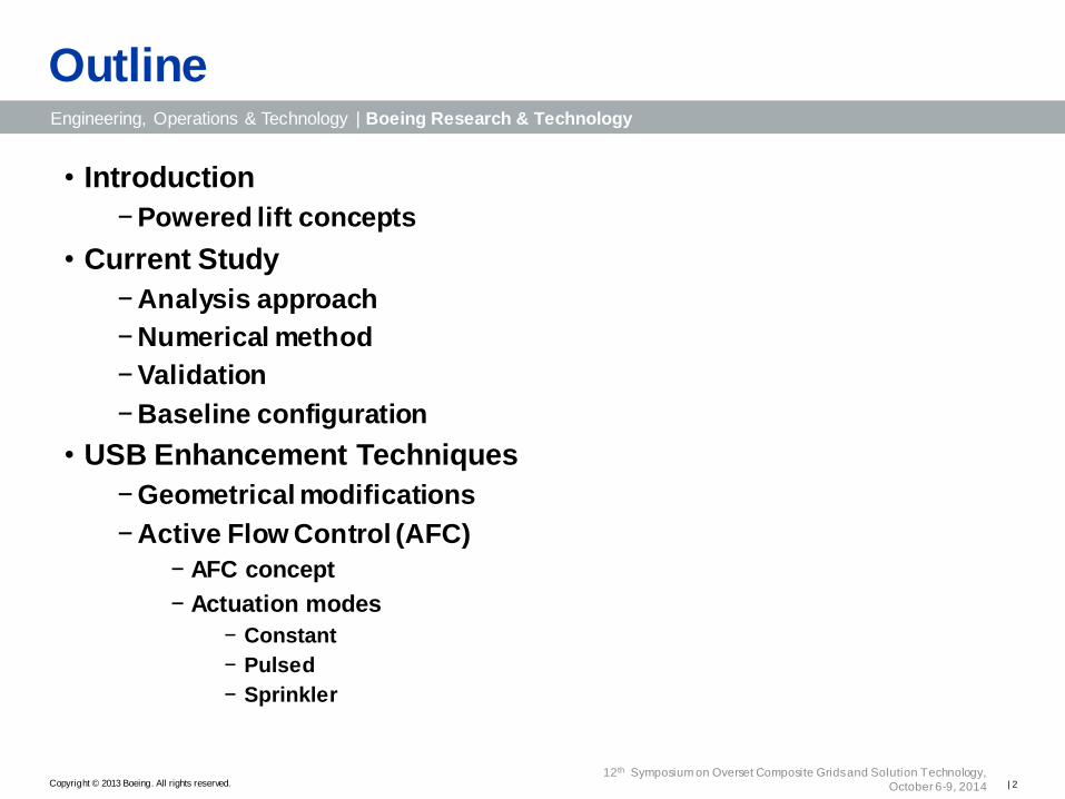
• Introduction
− Powered lift concepts
• Current Study
− Analysis approach
− Numerical method
− Validation
− Baseline configuration
• USB Enhancement Techniques
− Geometrical modifications
− Active Flow Control (AFC)
− AFC concept
− Actuation modes
− Constant
− Pulsed
− Sprinkler
Outline
| 2 12th Symposium on Overset Composite Grids and Solution Technology,
October 6-9, 2014
Engineering, Operations & Technology | Boeing Research & Technology
Copyright © 2013 Boeing. All rights reserved.
• Coanda Effect “Deviation of a plain jet of a fluid
that penetrates another fluid in the
vicinity of a convex wall”
Powered lift concepts
• Increase lift production by exploiting engine exhaust jet • Externally Blown Flaps (EBF)
• Internally Blown Flaps (IBF)
• Upper Surface Blowing (USB)
EBF
USB
Avrocar circa 1958
| 3 12th Symposium on Overset Composite Grids and Solution Technology,
October 6-9, 2014
Engineering, Operations & Technology | Boeing Research & Technology
Copyright © 2013 Boeing. All rights reserved.
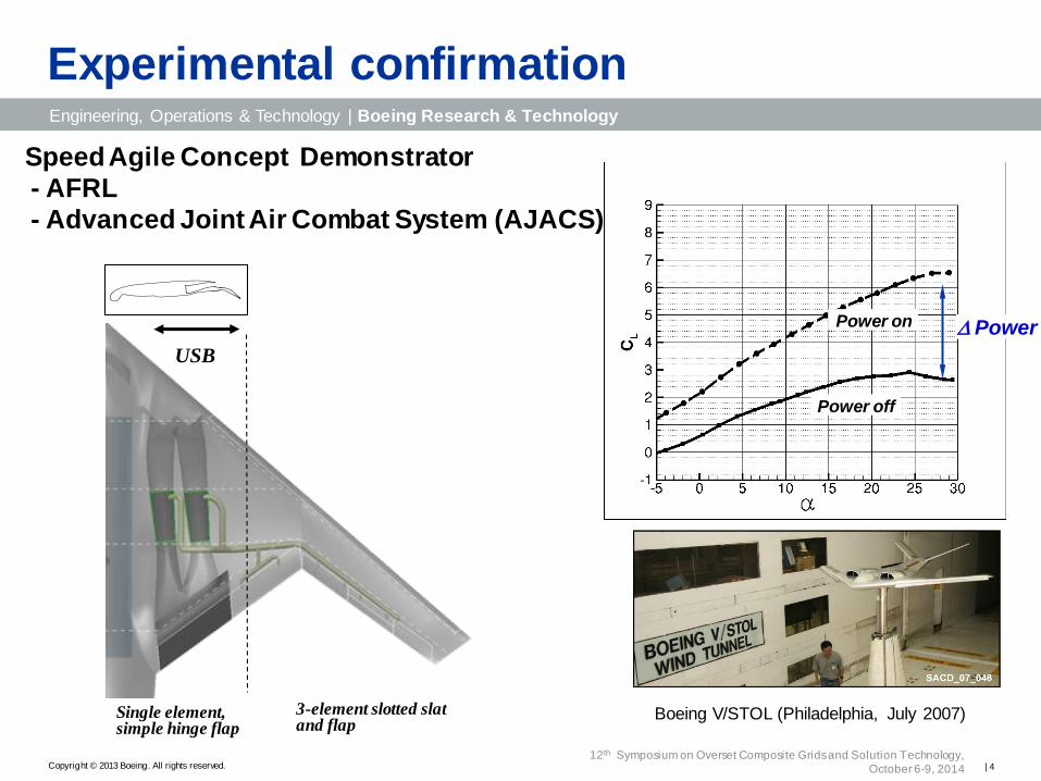
Experimental confirmation
Boeing V/STOL (Philadelphia, July 2007)
Power off
Power on Power
USB
Single element, simple hinge flap
3-element slotted slat and flap
Speed Agile Concept Demonstrator
- AFRL
- Advanced Joint Air Combat System (AJACS)
| 4 12th Symposium on Overset Composite Grids and Solution Technology,
October 6-9, 2014
Engineering, Operations & Technology | Boeing Research & Technology
Copyright © 2013 Boeing. All rights reserved.
Current study
• Problem
− Premature jet peeling-off degrades lifting capability
• Ratio of Jet thickness to surface radius of curvature:
− Thin jet
− Large radius of curvature
• Edge effects
− Spanwise extent of nozzle
− Edge vortex formation
• Objective
−Develop technologies for enhanced USB systems
• Approach −Geometrical modifications
−Active Flow Control
| 5 12th Symposium on Overset Composite Grids and Solution Technology,
October 6-9, 2014
Engineering, Operations & Technology | Boeing Research & Technology
Copyright © 2013 Boeing. All rights reserved.
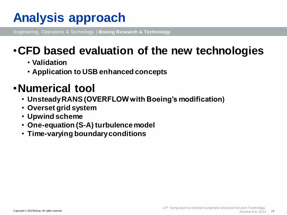
Analysis approach
•CFD based evaluation of the new technologies • Validation
• Application to USB enhanced concepts
•Numerical tool • Unsteady RANS (OVERFLOW with Boeing’s modification)
• Overset grid system
• Upwind scheme
• One-equation (S-A) turbulence model
• Time-varying boundary conditions
| 6 12th Symposium on Overset Composite Grids and Solution Technology,
October 6-9, 2014
Engineering, Operations & Technology | Boeing Research & Technology
Copyright © 2013 Boeing. All rights reserved.
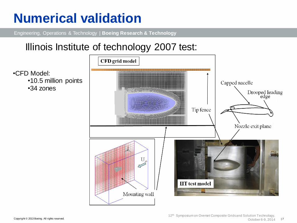
Numerical validation
Illinois Institute of technology 2007 test:
•CFD Model: •10.5 million points •34 zones
| 7 12th Symposium on Overset Composite Grids and Solution Technology,
October 6-9, 2014
Engineering, Operations & Technology | Boeing Research & Technology
Copyright © 2013 Boeing. All rights reserved.
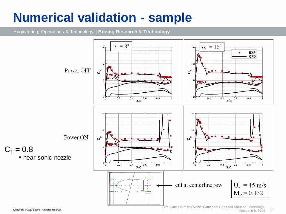
CT = 0.8 near sonic nozzle
Numerical validation - sample
| 8 12th Symposium on Overset Composite Grids and Solution Technology,
October 6-9, 2014
Engineering, Operations & Technology | Boeing Research & Technology
Copyright © 2013 Boeing. All rights reserved.
USB baseline configuration
Computational test bed is based on the IIT model
•Wing of constant chord between 2 vertical walls
•Full span flap
•Nozzle aspect ratio of 6
•AFC slots embedded in flap upper surface
•Height of slot is 0.2% chord
| 9 12th Symposium on Overset Composite Grids and Solution Technology,
October 6-9, 2014
Engineering, Operations & Technology | Boeing Research & Technology
Copyright © 2013 Boeing. All rights reserved.
USB flow features
Separation bubble
Engine plume (M=0.7)
Cross sectional vorticity
Power off Power on (takeoff)
Analysis tools •Extent of separation
•Shape of engine plume
•Vorticity field
Flow Features •Lift increment of 16%
•Flow reattachment behind engine
•Roll-up of engine plume at edge of nozzle
| 10 12th Symposium on Overset Composite Grids and Solution Technology,
October 6-9, 2014
Engineering, Operations & Technology | Boeing Research & Technology
Copyright © 2013 Boeing. All rights reserved.
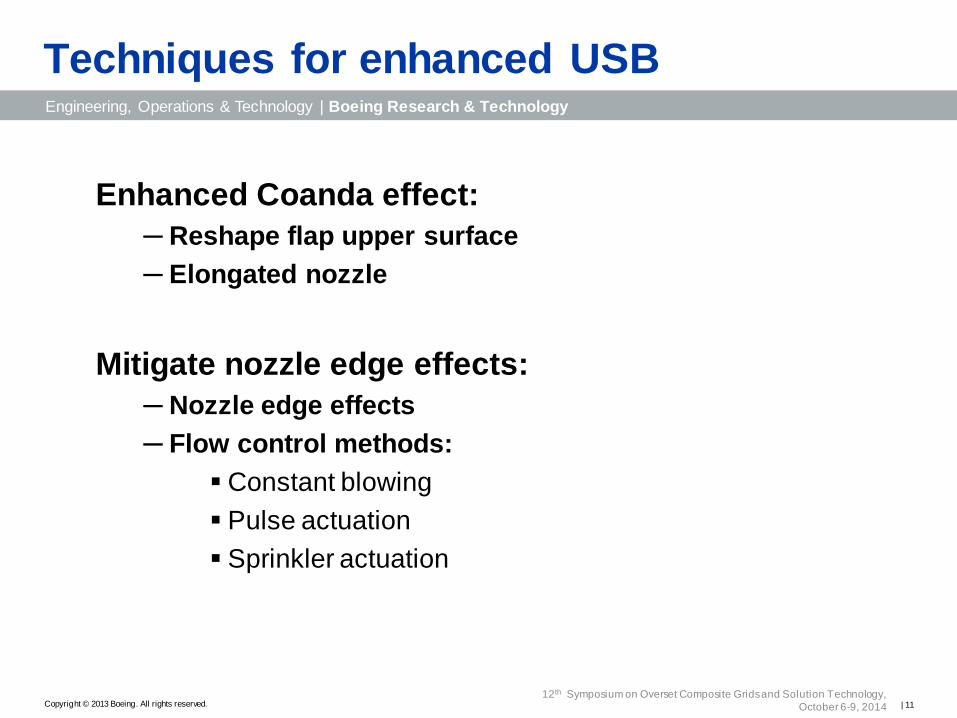
Techniques for enhanced USB
Enhanced Coanda effect:
─ Reshape flap upper surface
─ Elongated nozzle
Mitigate nozzle edge effects:
─ Nozzle edge effects
─ Flow control methods:
Constant blowing
Pulse actuation
Sprinkler actuation
| 11 12th Symposium on Overset Composite Grids and Solution Technology,
October 6-9, 2014
Engineering, Operations & Technology | Boeing Research & Technology
Copyright © 2013 Boeing. All rights reserved.
High curvature flap
• 4.7% increase in wing chord
• Lift increase of 12%
•Augmented Coanda effect over only 28% of wing
R = r
R = 2r
| 12 12th Symposium on Overset Composite Grids and Solution Technology,
October 6-9, 2014
Engineering, Operations & Technology | Boeing Research & Technology
Copyright © 2013 Boeing. All rights reserved.
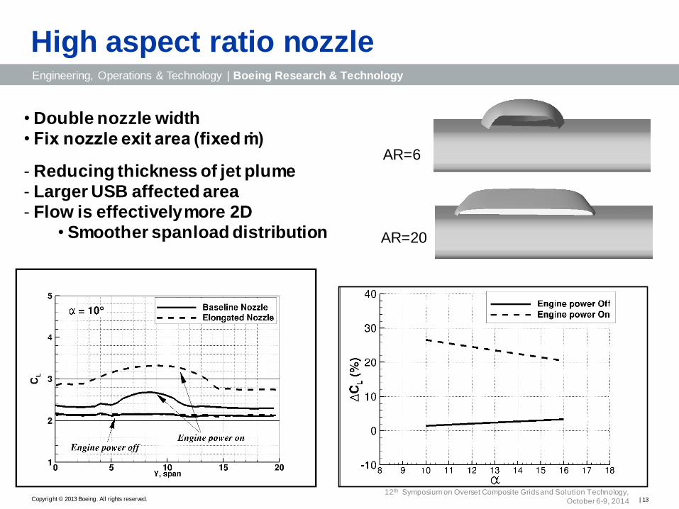
High aspect ratio nozzle
• Double nozzle width
• Fix nozzle exit area (fixed ṁ)
Reducing thickness of jet plume
Larger USB affected area
Flow is effectively more 2D
• Smoother spanload distribution AR=20
AR=6
| 13 12th Symposium on Overset Composite Grids and Solution Technology,
October 6-9, 2014
Engineering, Operations & Technology | Boeing Research & Technology
Copyright © 2013 Boeing. All rights reserved.
fence
Flap fences
• Control edge effects
• Prevent vortex roll-up
• Reduce three-dimensionality of flow
• Variable height
• Fixed or automatically deployed
Y
Z
X
| 14 12th Symposium on Overset Composite Grids and Solution Technology,
October 6-9, 2014
Engineering, Operations & Technology | Boeing Research & Technology
Copyright © 2013 Boeing. All rights reserved.
Power Off
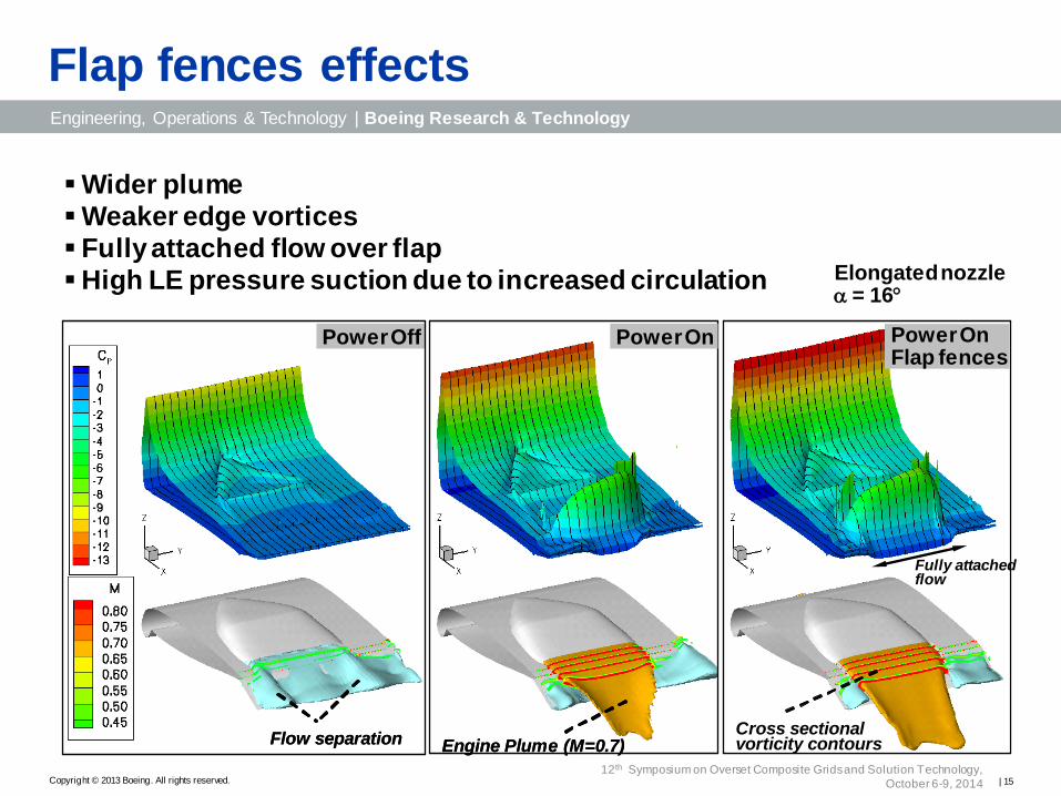
Flap fences effects
Flow separation
Power On Flap fences
Engine Plume (M=0.7) Cross sectional vorticity contours Flow separation
Power On Power On Flap fences
Engine Plume (M=0.7) Cross sectional vorticity contours
Fully attached flow
Elongated nozzle = 16
Wider plume
Weaker edge vortices
Fully attached flow over flap
High LE pressure suction due to increased circulation
| 15 12th Symposium on Overset Composite Grids and Solution Technology,
October 6-9, 2014
Engineering, Operations & Technology | Boeing Research & Technology
Copyright © 2013 Boeing. All rights reserved.
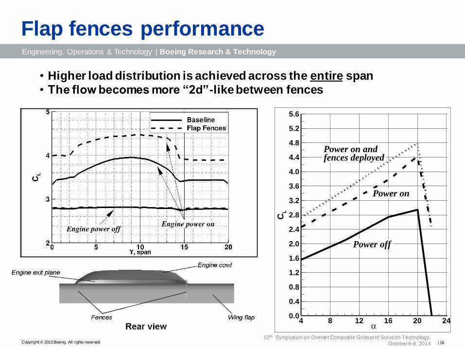
Flap fences performance
CL
4 8 12 16 20 240.0
0.4
0.8
1.2
1.6
2.0
2.4
2.8
3.2
3.6
4.0
4.4
4.8
5.2
5.6
Power on andfences deployed
Power off
Power on
• Higher load distribution is achieved across the entire span
• The flow becomes more “2d”-like between fences
| 16 12th Symposium on Overset Composite Grids and Solution Technology,
October 6-9, 2014
Engineering, Operations & Technology | Boeing Research & Technology
Copyright © 2013 Boeing. All rights reserved.
Active Flow Control
• Lift enhancement through delayed flow separation at
high angles of attack − Zero mass flow devices
− Fluidic device
o Source of air
− Engine bleed
− Dedicated compressor
o Actuation type
− Constant blowing from a fixed orifice
− Variable blowing
Pulse actuation ---periodic variation of jet velocity
Sprinkler actuation ---continuous swiveling of blowing jet
| 17 12th Symposium on Overset Composite Grids and Solution Technology,
October 6-9, 2014
Engineering, Operations & Technology | Boeing Research & Technology
Copyright © 2013 Boeing. All rights reserved.
Active Flow Control setup
Engine cowl Nozzle exit plane
Controller
Distribution valve
Extraction tube
Deflected wing flap
Engine exhaust
Ejection slots
Cut through the engine
Bleed off engine exhaust for
actuation at plume’s edges
| 18 12th Symposium on Overset Composite Grids and Solution Technology,
October 6-9, 2014
Engineering, Operations & Technology | Boeing Research & Technology
Copyright © 2013 Boeing. All rights reserved.
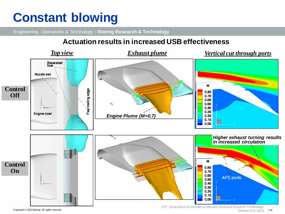
Constant blowing
AFC Off
AFC On
Control Off
Control On
Top view Exhaust plume Vertical cut through ports
Engine Plume (M=0.7)
Higher exhaust turning results in increased circulation
Actuation results in increased USB effectiveness
| 19 12th Symposium on Overset Composite Grids and Solution Technology,
October 6-9, 2014
Engineering, Operations & Technology | Boeing Research & Technology
Copyright © 2013 Boeing. All rights reserved.
Constant blowing (cont.)
Baseline Pattern 1 Pattern 2 Pattern 3
Alternative actuation patterns:
• multiple flight conditions
• uncertainties in plume location
no actuation
| 20 12th Symposium on Overset Composite Grids and Solution Technology,
October 6-9, 2014
Engineering, Operations & Technology | Boeing Research & Technology
Copyright © 2013 Boeing. All rights reserved.
•Reduce bleed air requirement
−Reduce engine size/weight
•Wide range of actuations modes
− Physical distribution
− Frequency
− Phase
Pulsed actuation
| 21 12th Symposium on Overset Composite Grids and Solution Technology,
October 6-9, 2014
Engineering, Operations & Technology | Boeing Research & Technology
Copyright © 2013 Boeing. All rights reserved.
Engine exhaust
Baseline
Separated flow
Intermittent (instantaneous)
Pulsed actuation cleans up flow separation
Pulsed actuation flow field
| 22 12th Symposium on Overset Composite Grids and Solution Technology,
October 6-9, 2014
Engineering, Operations & Technology | Boeing Research & Technology
Copyright © 2013 Boeing. All rights reserved.
Alternate between left and right blowing
Constant actuation
Intermittent actuation
RHS stroke
LHS stroke
Pulsed actuation effectiveness
1
2
mBl
- Bleed for actuation
mEng
- Nozzle mass flow rate
3 pairs
2
1
3 pairs
mBl
/ mEng
C
L
0.00 0.05 0.10 0.150.0
0.2
0.4
0.6
0.8
1.0
1.2
1.4
Constant
Intermittent
Original nozzle = 10
| 23 12th Symposium on Overset Composite Grids and Solution Technology,
October 6-9, 2014
Engineering, Operations & Technology | Boeing Research & Technology
Copyright © 2013 Boeing. All rights reserved.
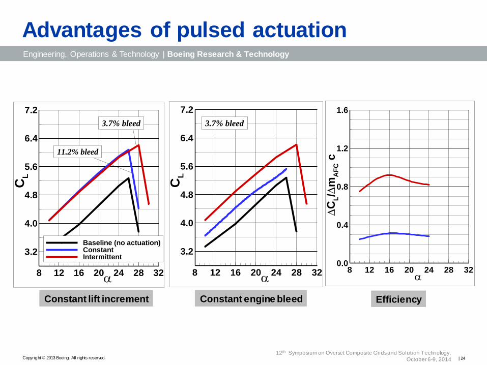
Constant engine bleed Constant lift increment
C
L/
mA
FC
c
8 12 16 20 24 28 320.0
0.4
0.8
1.2
1.6
Efficiency
Advantages of pulsed actuation
Constant engine bleed Constant lift increment
11.2% bleed
Power off
3.7% bleed
CL
8 12 16 20 24 28 32
3.2
4.0
4.8
5.6
6.4
7.2
Baseline (no actuation)ConstantIntermittent
Power off
3.7% bleed
CL
8 12 16 20 24 28 32
3.2
4.0
4.8
5.6
6.4
7.2
| 24 12th Symposium on Overset Composite Grids and Solution Technology,
October 6-9, 2014
Engineering, Operations & Technology | Boeing Research & Technology
Copyright © 2013 Boeing. All rights reserved.
Pulsed actuation animation
Elongated nozzle
| 25 12th Symposium on Overset Composite Grids and Solution Technology,
October 6-9, 2014
Engineering, Operations & Technology | Boeing Research & Technology
Copyright © 2013 Boeing. All rights reserved.
Sprinkler Actuation
•Multiple flight conditions requires flexibility:
• Edge of jet plume might vary
• A-priori placement of ports may not be practical
• Need a “wide area coverage” device
Sprinkler actuator :
• Continuous/swiveling blowing
• Swiveling nozzle
• Louver/vanes system
Vane
| 26 12th Symposium on Overset Composite Grids and Solution Technology,
October 6-9, 2014
Engineering, Operations & Technology | Boeing Research & Technology
Copyright © 2013 Boeing. All rights reserved.
Sprinkler actuation - results
Baseline
Instantaneous flow structure (limit cycle)
• Pair of jets
• Oscillating ±30º from side to side
• Frequency of 10Hz
| 27 12th Symposium on Overset Composite Grids and Solution Technology,
October 6-9, 2014
Engineering, Operations & Technology | Boeing Research & Technology
Copyright © 2013 Boeing. All rights reserved.
Summary
• Upper surface blowing is an effective tool in lift enhancement
• Degradation in USB effectiveness due to − Premature separation
− Nozzle edge effects
• Techniques for lift enhancement: − Geometrical modifications:
Flap upper surface
Larger aspect-ratio nozzle
Flap fences
− Active Flow Control
Constant actuation
Pulsed actuation for increase efficiency
Sprinkler actuation for increased flexibility
| 28 12th Symposium on Overset Composite Grids and Solution Technology,
October 6-9, 2014