25
Prepared by Md. Shaha Jalal Mechanical Maintenance Technician
| Date post: | 18-Jul-2015 |
| Category: |
Engineering |
| Upload: | shah-jalal |
| View: | 309 times |
| Download: | 23 times |

Prepared by
Md. Shaha Jalal Mechanical Maintenance Technician
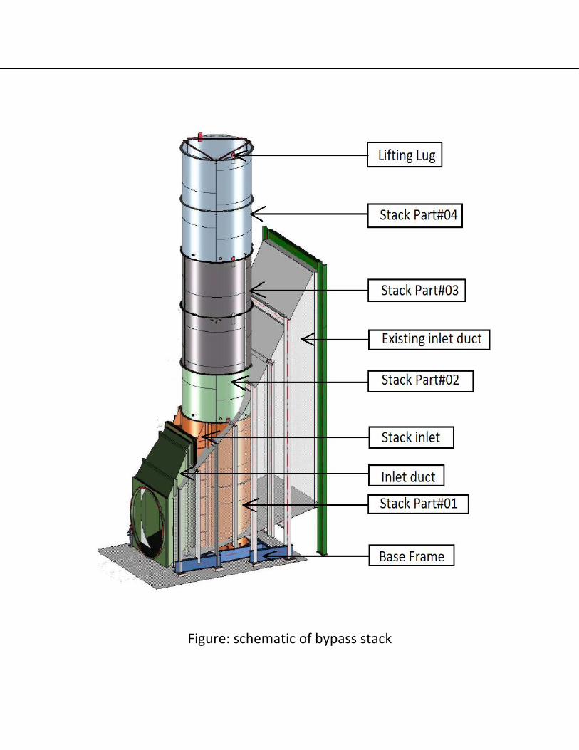
Figure: schematic of bypass stack
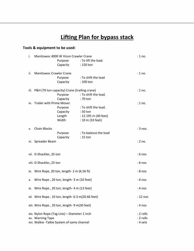
Lifting Plan for bypass stack
Tools & equipment to be used:
i. Manitowoc 4000 W Vicon Crawler Crane : 1 no. Purpose : To lift the load. Capacity : 150 ton
ii. Manitowoc Crawler Crane : 1 no. Purpose : To shift the load Capacity : 100 ton
iii. P&H (70 ton capacity) Crane (trailing crane) : 1 no. Purpose : To shift the load. Capacity : 70 ton
iv. Trailer with Prime Mover. : 1 no. Purpose : To shift the load. Capacity : 50 ton Length : 12.195 m (40 feet) Width : 10 m (33 feet)
v. Chain Blocks : 3 nos. Purpose : To balance the load Capacity : 15 ton
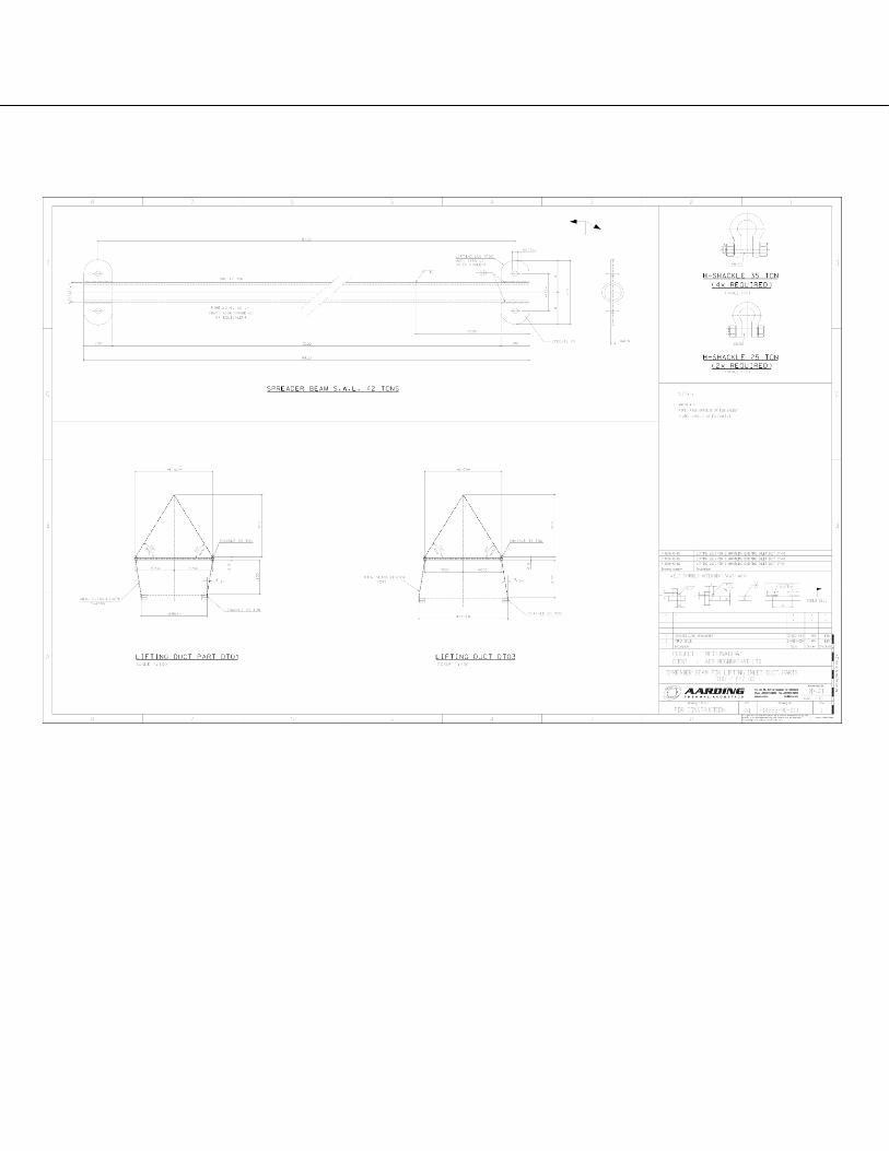
vi. Spreader Beam : 2 no.
vii. D-Shackles ,35 ton : 6 nos
viii. D-Shackles ,25 ton : 6 nos
ix. Wire Rope, 20 ton, length- 2 m (6.56 ft) : 8 nos
x. Wire Rope , 20 ton, length- 3 m (10 feet) : 4 nos
xi. Wire Rope , 20 ton, length- 4 m (13 feet) : 4 nos
xii. Wire Rope , 10 ton, length- 6.3 m(20.66 feet) : 12 nos
xiii. Wire Rope , 20 ton, length- 9 m(30 feet) : 4 nos
xiv. Nylon Rope (Tag Line) – Diameter 1 inch : 2 rolls xv. Warning Tape : 2 rolls xvi. Walkie -Talkie System of same channel : 4 sets
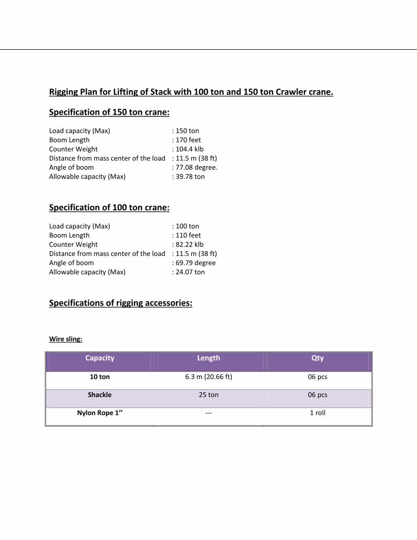
Rigging Plan for Lifting of Stack with 100 ton and 150 ton Crawler crane.
Specification of 150 ton crane:
Load capacity (Max) : 150 ton Boom Length : 170 feet Counter Weight : 104.4 klb Distance from mass center of the load : 11.5 m (38 ft) Angle of boom : 77.08 degree. Allowable capacity (Max) : 39.78 ton
Specification of 100 ton crane:
Load capacity (Max) : 100 ton Boom Length : 110 feet Counter Weight : 82.22 klb Distance from mass center of the load : 11.5 m (38 ft) Angle of boom : 69.79 degree Allowable capacity (Max) : 24.07 ton
Specifications of rigging accessories:
Wire sling:
Capacity Length Qty
10 ton 6.3 m (20.66 ft) 06 pcs
Shackle 25 ton 06 pcs
Nylon Rope 1’’ --- 1 roll
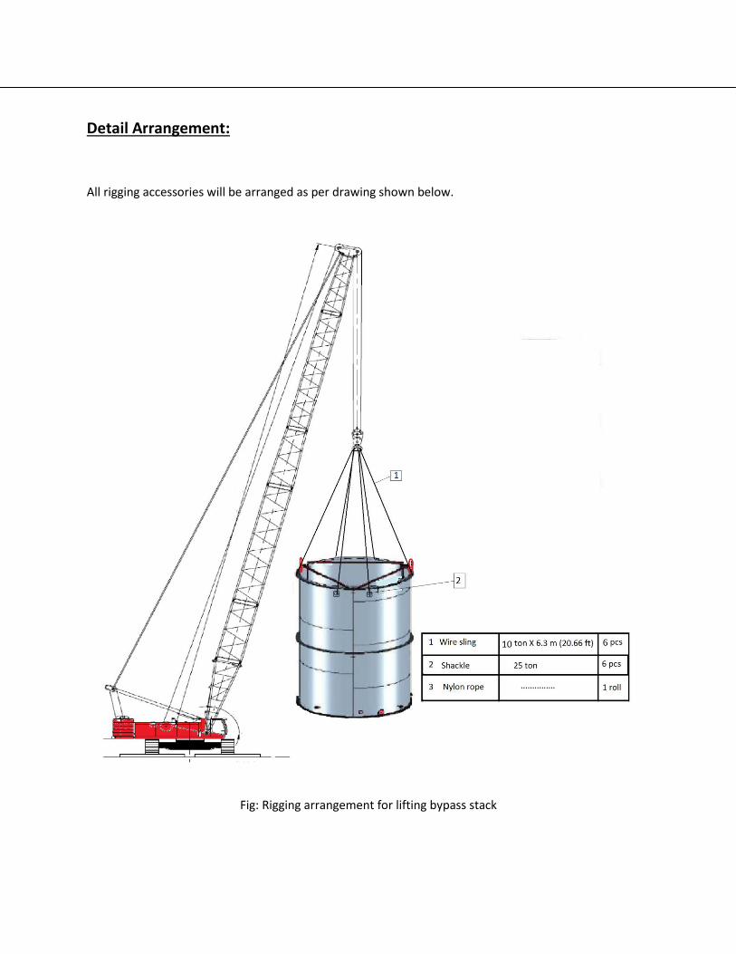
Detail Arrangement:
All rigging accessories will be arranged as per drawing shown below.
Fig: Rigging arrangement for lifting bypass stack
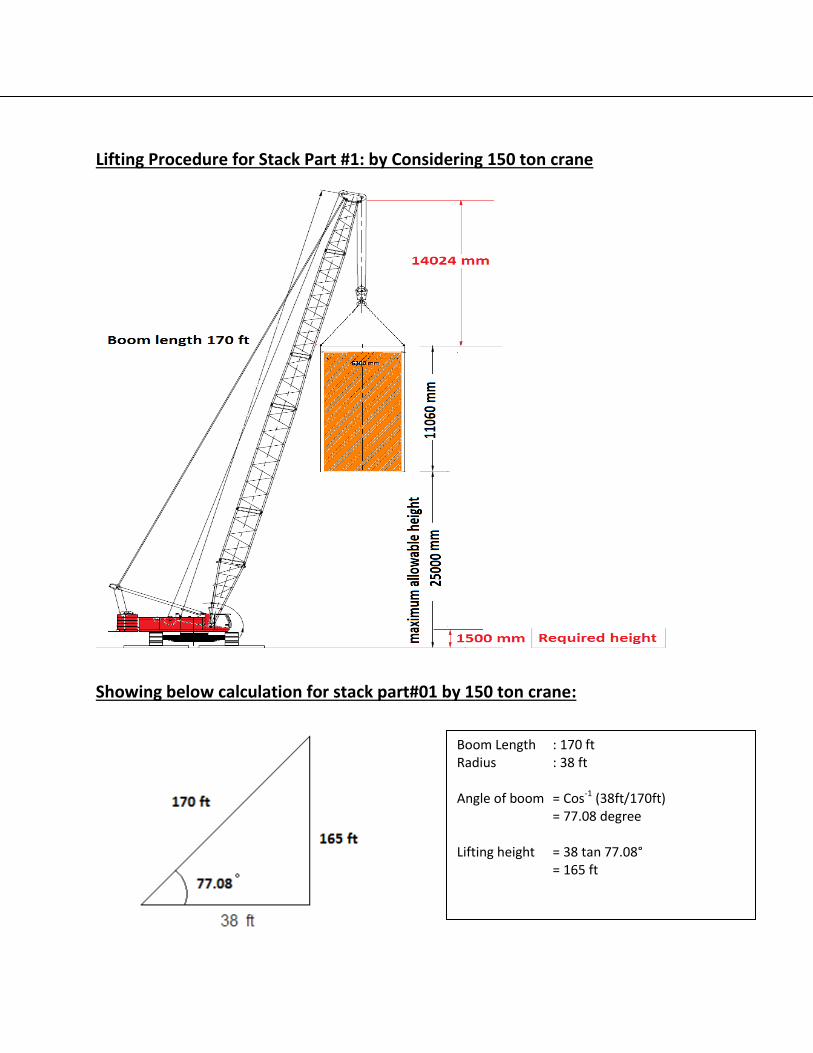
Lifting Procedure for Stack Part #1: by Considering 150 ton crane
Showing below calculation for stack part#01 by 150 ton crane:
Boom Length : 170 ft Radius : 38 ft Angle of boom = Cos-1 (38ft/170ft) = 77.08 degree Lifting height = 38 tan 77.08° = 165 ft

Fig: Lifting of Stack part#01 by 150 ton crane
Lifting Procedure for Stack Part #1: by Considering 100 ton crane
Available lifting height: = 165 – Load height – boom top to load touching point distance = 165– 37 – 45.5 = 82.5 ft
Lifting accessories length =20.66 ft Load Capacity : 39.78 ton (from load chart: annex 02) Load weight : 15 ton Accessories : 2 ton Total load weight : 17 ton
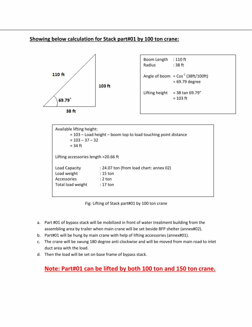
Showing below calculation for Stack part#01 by 100 ton crane:
Fig: Lifting of Stack part#01 by 100 ton crane
a. Part #01 of bypass stack will be mobilized in front of water treatment building from the
assembling area by trailer when main crane will be set beside BFP shelter (annex#02).
b. Part#01 will be hung by main crane with help of lifting accessories (annex#01).
c. The crane will be swung 180 degree anti clockwise and will be moved from main road to inlet
duct area with the load.
d. Then the load will be set on base frame of bypass stack.
Note: Part#01 can be lifted by both 100 ton and 150 ton crane.
Boom Length : 110 ft Radius : 38 ft Angle of boom = Cos-1 (38ft/100ft) = 69.79 degree Lifting height = 38 tan 69.79° = 103 ft
Available lifting height: = 103 – Load height – boom top to load touching point distance = 103 – 37 – 32 = 34 ft
Lifting accessories length =20.66 ft
Load Capacity : 24.07 ton (from load chart: annex 02) Load weight : 15 ton Accessories : 2 ton Total load weight : 17 ton
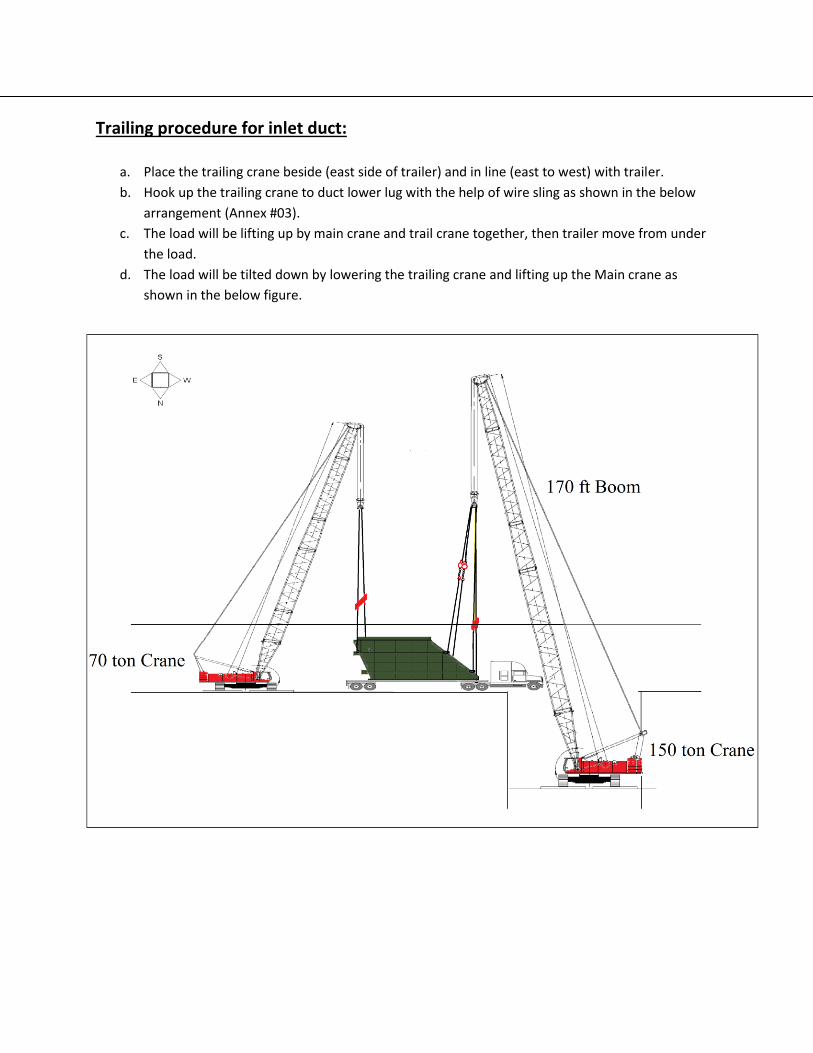
Trailing procedure for inlet duct:
a. Place the trailing crane beside (east side of trailer) and in line (east to west) with trailer.
b. Hook up the trailing crane to duct lower lug with the help of wire sling as shown in the below
arrangement (Annex #03).
c. The load will be lifting up by main crane and trail crane together, then trailer move from under
the load.
d. The load will be tilted down by lowering the trailing crane and lifting up the Main crane as
shown in the below figure.
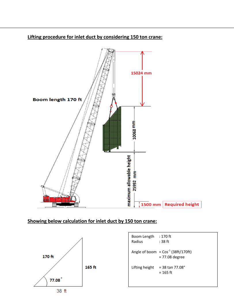
Lifting procedure for inlet duct by considering 150 ton crane:
Showing below calculation for inlet duct by 150 ton crane:
Boom Length : 170 ft Radius : 38 ft Angle of boom = Cos-1 (38ft/170ft) = 77.08 degree Lifting height = 38 tan 77.08° = 165 ft
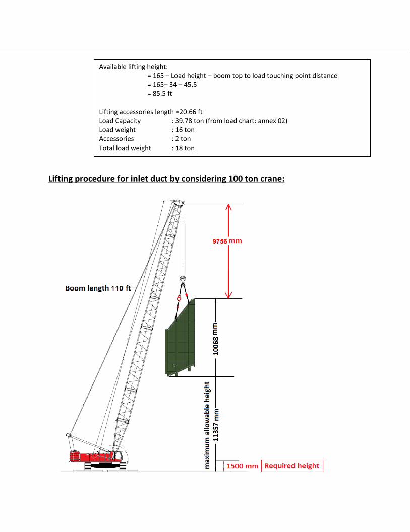
Lifting procedure for inlet duct by considering 100 ton crane:
Available lifting height: = 165 – Load height – boom top to load touching point distance = 165– 34 – 45.5 = 85.5 ft
Lifting accessories length =20.66 ft Load Capacity : 39.78 ton (from load chart: annex 02) Load weight : 16 ton Accessories : 2 ton Total load weight : 18 ton

a. Inlet duct part of bypass stack will be mobilized in front of water treatment building from the
assembling area by trailer when main crane will be set beside BFP shelter (annex#02).
b. Duct part will be hung by main crane with help of lifting accessories (annex#03).
c. The crane will be swung 180 degree anti clockwise and will be moved from main road to inlet
duct area with the load.
d. Then the load will be set on base frame of bypass stack.
Inlet duct can be lifted by both 100 ton and 150 ton crane.
Boom Length : 110 ft Radius : 38 ft Angle of boom = Cos-1 (38ft/100ft) = 69.79 degree Lifting height = 38 tan 69.79° = 103 ft
Available lifting height: = 103 – Load height – boom top to load touching point distance = 103 – 34 – 32 = 37 ft
Lifting accessories length =20.66 ft
Load Capacity : 24.07 ton (from load chart: annex 02) Load weight : 16 ton Accessories : 2 ton Total load weight : 18 ton
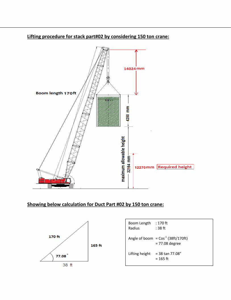
Lifting procedure for stack part#02 by considering 150 ton crane:
Showing below calculation for Duct Part #02 by 150 ton crane:
Boom Length : 170 ft Radius : 38 ft Angle of boom = Cos-1 (38ft/170ft) = 77.08 degree Lifting height = 38 tan 77.08° = 165 ft

Fig: Lifting of stack part#02 by 150 ton crane
Lifting procedure for stack part #02 by considering 100 ton crane:
Available lifting height: = 165 – Load height – boom top to load touching point distance = 165– 14 – 45.5 = 105.5 ft
Lifting accessories length =20.66 ft
Load Capacity : 39.78 ton (from load chart: annex 02) Load weight : 10 ton Accessories : 2 ton Total load weight : 12 ton
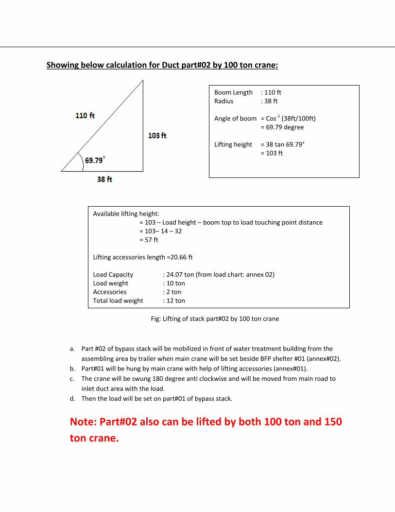
Showing below calculation for Duct part#02 by 100 ton crane:
Fig: Lifting of stack part#02 by 100 ton crane
a. Part #02 of bypass stack will be mobilized in front of water treatment building from the
assembling area by trailer when main crane will be set beside BFP shelter #01 (annex#02).
b. Part#01 will be hung by main crane with help of lifting accessories (annex#01).
c. The crane will be swung 180 degree anti clockwise and will be moved from main road to
inlet duct area with the load.
d. Then the load will be set on part#01 of bypass stack.
Note: Part#02 also can be lifted by both 100 ton and 150
ton crane.
Boom Length : 110 ft Radius : 38 ft Angle of boom = Cos-1 (38ft/100ft) = 69.79 degree Lifting height = 38 tan 69.79° = 103 ft
Available lifting height: = 103 – Load height – boom top to load touching point distance = 103– 14 – 32 = 57 ft
Lifting accessories length =20.66 ft
Load Capacity : 24.07 ton (from load chart: annex 02) Load weight : 10 ton Accessories : 2 ton Total load weight : 12 ton
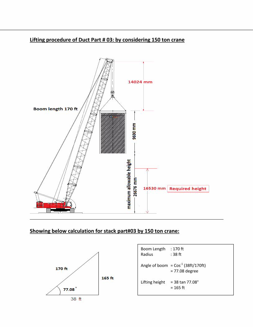
Lifting procedure of Duct Part # 03: by considering 150 ton crane
Showing below calculation for stack part#03 by 150 ton crane:
Boom Length : 170 ft Radius : 38 ft Angle of boom = Cos-1 (38ft/170ft) = 77.08 degree Lifting height = 38 tan 77.08° = 165 ft

Fig: Lifting of stack part#03 150 ton crane
Lifting procedure for stack part#03 considering by 100 ton crane:
Available lifting height: = 165 – Load height – boom top to load touching point distance = 165– 32 – 45.5 = 87.5 ft
Lifting accessories length =20.66 ft
Load Capacity : 39.78 ton (from load chart: annex 02) Load weight : 23 ton Accessories : 2 ton Total load weight : 25 ton
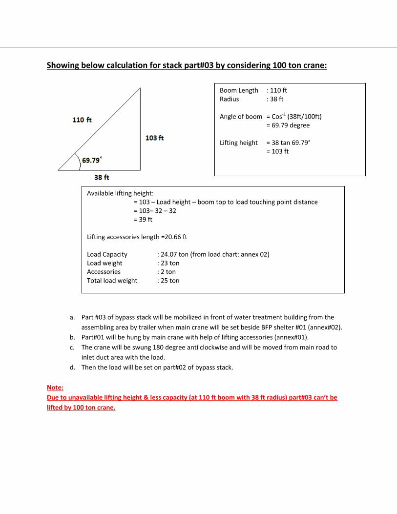
Showing below calculation for stack part#03 by considering 100 ton crane:
a. Part #03 of bypass stack will be mobilized in front of water treatment building from the
assembling area by trailer when main crane will be set beside BFP shelter #01 (annex#02).
b. Part#01 will be hung by main crane with help of lifting accessories (annex#01).
c. The crane will be swung 180 degree anti clockwise and will be moved from main road to
inlet duct area with the load.
d. Then the load will be set on part#02 of bypass stack.
Note:
Due to unavailable lifting height & less capacity (at 110 ft boom with 38 ft radius) part#03 can’t be
lifted by 100 ton crane.
Boom Length : 110 ft Radius : 38 ft Angle of boom = Cos-1 (38ft/100ft) = 69.79 degree Lifting height = 38 tan 69.79° = 103 ft
Available lifting height: = 103 – Load height – boom top to load touching point distance = 103– 32 – 32 = 39 ft
Lifting accessories length =20.66 ft
Load Capacity : 24.07 ton (from load chart: annex 02) Load weight : 23 ton Accessories : 2 ton Total load weight : 25 ton

Lifting procedure of Duct Part # 04: by considering 150 ton crane
Showing below calculation for Stack Part # 04: by considering 150 ton crane
Boom Length : 170 ft Radius : 38 ft Angle of boom = Cos-1 (38ft/170ft) = 77.08 degree Lifting height = 38 tan 77.08° = 165 ft
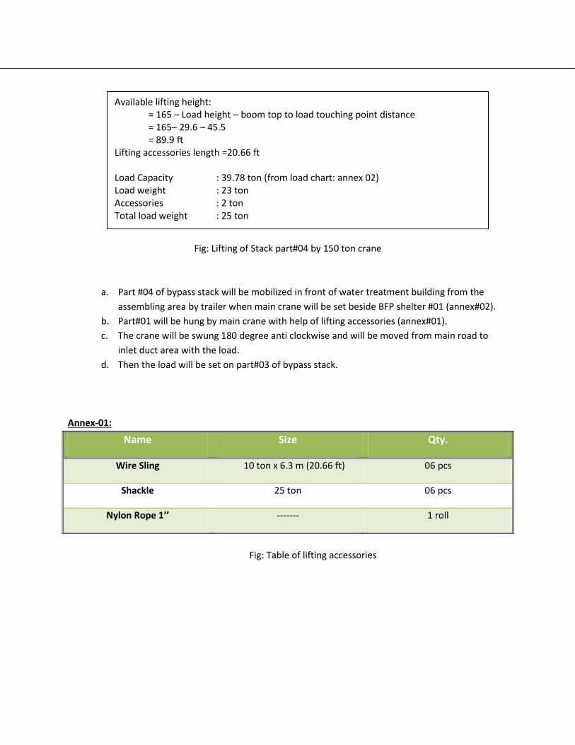
Fig: Lifting of Stack part#04 by 150 ton crane
a. Part #04 of bypass stack will be mobilized in front of water treatment building from the
assembling area by trailer when main crane will be set beside BFP shelter #01 (annex#02).
b. Part#01 will be hung by main crane with help of lifting accessories (annex#01).
c. The crane will be swung 180 degree anti clockwise and will be moved from main road to
inlet duct area with the load.
d. Then the load will be set on part#03 of bypass stack.
Annex-01:
Name Size Qty.
Wire Sling 10 ton x 6.3 m (20.66 ft) 06 pcs
Shackle 25 ton 06 pcs
Nylon Rope 1’’ ------- 1 roll
Fig: Table of lifting accessories
Available lifting height: = 165 – Load height – boom top to load touching point distance = 165– 29.6 – 45.5 = 89.9 ft
Lifting accessories length =20.66 ft
Load Capacity : 39.78 ton (from load chart: annex 02) Load weight : 23 ton Accessories : 2 ton Total load weight : 25 ton

Fig: Drawing of load width and height

Annex-02:
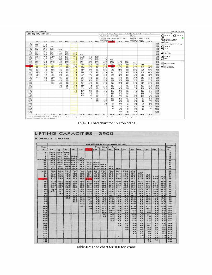
Table-01: Load chart for 150 ton crane.
Table-02: Load chart for 100 ton crane

Annex: 03
Name Size Qty.
Wire Sling 20 ton x 2 m (6.56 ft) 4pcs
Wire Sling 20 ton x 3 m (9.84 ft) 8pcs
Shackle 25 ton 14pcs
Chain block 10 ton 2pcs
Spreader beam 42 ton, 8400X219mm 2pcs
Nylon Rope 1’’ ------- 1 roll