LIFTING TRANSFORMS ON GRAPHS FOR VIDEO CODING Eduardo Mart´ ınez-Enr´ ıquez a and Antonio Ortega b a Department of Signal Theory and Communications, Universidad Carlos III; b Department of Electrical Engineering, University of Southern California ABSTRACT We present a new graph-based transform for video signals using wavelet lifting. Graphs are created to capture spatial and temporal correlations in video sequences. Our new transforms allow spatial and temporal correlation to be jointly exploited, in contrast to existing techniques, such as motion compensated temporal filtering, which can be seen as “separable” transforms, since spatial and temporal filtering are performed separately. We design efficient ways to form the graphs and to design the prediction and update filters for different levels of the lifting transform as a function of expected degree of correlation between pixels. Our initial results are promising, with improvements in performance as compared to existing methods in terms of PSNR as a function of the percentage of retained coefficients of the transform. Index Terms— Wavelet transforms, Video coding, MCTF, Lifting, Graphs 1. INTRODUCTION The lifting scheme is an intuitive and structurally invertible approach to construct multiresolution signal representations [1]. Lifting based wavelet transforms have been widely used for image and video processing, mainly in the last ten years, and there are many works about these topics in the literature. In the field of image coding, lifting-based wavelets have been used to capture directional information, avoiding filtering across the object edges, giving rise to very efficient representations of the image. Examples can be found in [2], [3] or [4]. For video coding, lifting is usually applied in the temporal domain. The main multiresolution decomposition structures in wavelet-based video coding are t +2D and 2D + t. In the former, the video sequence is first filtered in the temporal direction along the motion trajectories (motion-compensated temporal filtering-MCTF) and then a 2D wavelet transform is carried out in the spatial domain [5]. In the latter, each frame is firstly wavelet transformed in the spatial domain, followed by MCTF. Focusing in the temporal domain, representative examples of MCTF implementations are [6] and [7], which use motion-compensated lifting steps to implement the temporal wavelet transform, filtering along a set of motion trajectories described by a specific motion model. These approaches can be described as “separable” in that spatial and temporal filtering are applied in separate steps. In all of these works, in order to perform the prediction and update steps of the lifting scheme, the input sequence is split into update (even frames) and prediction (odd frames) subsequences, and for each level of the transform, the prediction subsequence is predicted from the update subsequence giving rise to the high-pass subband sequence, and the update subsequence is updated by using a filtered version of the prediction one, thus obtaining the low-pass subband sequence. In cases in which the motion model cannot accurately capture the real motion of the scene, this kind of splitting into even and odd frames will lead to the linking of update and prediction pixels with very different luminance values. In this way, prediction frames will be poorly predicted from update
Transcript
LIFTING TRANSFORMS ON GRAPHS FOR VIDEO CODING
Eduardo Martınez-Enrıqueza and Antonio Ortegab
a Department of Signal Theory and Communications, Universidad Carlos III;b Department of Electrical Engineering, University of Southern California
ABSTRACT
We present a new graph-based transform for video signals using wavelet lifting. Graphs are createdto capture spatial and temporal correlations in video sequences. Our new transforms allow spatialand temporal correlation to be jointly exploited, in contrast to existing techniques, such as motioncompensated temporal filtering, which can be seen as “separable” transforms, since spatial andtemporal filtering are performed separately. We design efficient ways to form the graphs and todesign the prediction and update filters for different levels of the lifting transform as a function ofexpected degree of correlation between pixels. Our initialresults are promising, with improvementsin performance as compared to existing methods in terms of PSNR as a function of the percentageof retained coefficients of the transform.
Index Terms— Wavelet transforms, Video coding, MCTF, Lifting, Graphs
1. INTRODUCTION
The lifting scheme is an intuitive and structurally invertible approach to construct multiresolutionsignal representations [1]. Lifting based wavelet transforms have been widely used for image andvideo processing, mainly in the last ten years, and there aremany works about these topics in theliterature. In the field of image coding, lifting-based wavelets have been used to capture directionalinformation, avoiding filtering across the object edges, giving rise to very efficient representationsof the image. Examples can be found in [2], [3] or [4]. For video coding, lifting is usually appliedin the temporal domain. The main multiresolution decomposition structures in wavelet-based videocoding aret + 2D and2D + t. In the former, the video sequence is first filtered in the temporaldirection along the motion trajectories (motion-compensated temporal filtering-MCTF) and then a2D wavelet transform is carried out in the spatial domain [5]. In the latter, each frame is firstlywavelet transformed in the spatial domain, followed by MCTF. Focusing in the temporal domain,representative examples of MCTF implementations are [6] and [7], which use motion-compensatedlifting steps to implement the temporal wavelet transform,filtering along a set of motion trajectoriesdescribed by a specific motion model. These approaches can bedescribed as “separable” in thatspatial and temporal filtering are applied in separate steps.
In all of these works, in order to perform the prediction and update steps of the lifting scheme,the input sequence is split into update (even frames) and prediction (odd frames) subsequences, andfor each level of the transform, the prediction subsequenceis predicted from the update subsequencegiving rise to the high-pass subband sequence, and the update subsequence is updated by usinga filtered version of the prediction one, thus obtaining the low-pass subband sequence. In casesin which the motion model cannot accurately capture the realmotion of the scene, this kind ofsplitting into even and odd frames will lead to the linking ofupdate and prediction pixels with verydifferent luminance values. In this way, prediction frameswill be poorly predicted from update
frames, leading to significant energy in the high pass subband sequence, and thus relatively lowenergy compaction. Moreover, when using MCTF, problems arise due to occlusions and uncoveredareas (pixels that are filtered several times or are not filtered at all). Some authors handle thisproblem by identifying unconnected and multiple connectedpixels and adapting the predict andupdate operators accordingly (e.g., [8]).
The key novelty in our work is describing the video sequence as a graph of connected pixels andapplying the lifting transform on this graph. Given that pixels (the nodes of the graph) are linked tospatial or temporal neighbors (or both) it is easy to make useof spatio-temporal filtering operations,selected to follow spatio-temporal directions of maximum correlation between pixels. Similar to[2], [3], bandelets [9] or directionlets [10], examples of directional wavelet transforms whose ba-sis functions are adapted to any 2-dimensional direction inthe spatial domain for efficient imagerepresentation, our approach can filter following any 3-dimensional direction of the spatio-temporaldomain. Moreover, our proposed scheme can avoid problems due to occlusions and uncoveredareas, leading to simple critically sampled invertible transform.
Our starting point is the lifting-based wavelet transform for graph data presented in [11]. Weextend the transform toN -levels of decomposition and apply it to video coding. The connectionsin the graph are constructed in such a way that pixels expected to have similar luminance will tendto be connected. Therefore, the prediction of a pixel from its graph neighbors can be more accurate,leading to reduced energy in the high-pass subband at any decomposition level of the transform. Toget a more accurate prediction, the connection between any pair of pixels is weighted as a functionof estimates of correlation between the pixels, i.e., higher expected correlation tends to lead to betterprediction and larger prediction weights. This weighting will be used in the design of the predictionand update filters and in the construction of the graph in successive levels of decomposition, thushelping improve prediction at all levels.
The links between pixels can be temporal (pixels connected by means of a motion model) orspatial (one-hop neighbor pixels that do not cross edges), and the number of neighbors that one pixelcan have in the graph can vary locally so that we can have flexibility in designing the correspondingfiltering operations. Our work could be considered as a generalization of wavelet-based video cod-ing that gives rise to a more versatile solution where spatial and temporal operations are no longerseparable. The transform requires that some side information be sent to the decoder, so that the samegraph can be constructed at both encoder and decoder. Specifically, temporal information (motionvectors) and spatial information (edges) have to be sent. Interms of non-linear approximation weachieve average gains of 2.3 dB and 1.3 dB as compared to a DCT based encoder and the LIMATmethod [6], respectively.
The rest of this paper is organized as follows. In Section 2 wedescribe in detail our novel videocoding scheme based on lifting transforms on graphs. In Section 3 we provide experimental results.Finally, conclusions and future work are given in Section 4.
2. PROPOSED SCHEME
2.1. Lifting Transforms on Graphs
The lifting approach for wavelet construction and its relation with the multiresolution analysis arepresented in [1]. To perform the transform and ensure its invertibility, the input data at each specificlevel of decompositionj should be split into prediction (Pj) and update (Uj) disjoint sets, and thepredict (pm,j(m ∈ Pj)) and update (un,j(n ∈ Uj)) filters should be specified. Then, following thenotation employed in [12], them-th detaildm andn-th smoothsn coefficients can be computed as:
Split j =1 p m, j =1 u n, j =1
x
U j =1 s
n , j =1
d m, j =1 P
j =1 +
+
...
Split j =2 p m, j =2 u n, j =2
+
+
d m, j =2
s n , j =2
P j =2
U j =2
Fig. 1. Lifting scheme. Two levels of decomposition.
dm,j = sm,j−1 +∑
k∈Uj
pm,j(k)sk,j−1
sn,j = sn,j−1 +∑
k∈Pj
un,j(k)dk,j. (1)
The smooth coefficients at(j−1)-th decomposition level (sn,j−1) are projected onto the approx-imation and detail subspaces, yielding, respectively, thesmooth (sn,j) and detail (dm,j) coefficientsat thej-th decomposition level. Applying this process iteratively gives rise to a multiresolutiondecomposition. In Figure 1 the lifting structure for two levels of decomposition is shown. Note thatthe data at levelj = 0 will be the original raw data (the luminance of the pixels in our case), andwill be denoted asxg, soxg = sn,j=0, whereg is the pixel index. Forj > 0, sn,j will be the lowpass version (smooth projection) of the(j − 1)-th level.
Lifting-based wavelet transforms on trees are applied to image coding in [2] and to sensornetworks applications in [12]. In these works, the authors split the data into prediction and updatesets at each level of decomposition according to their depthwith respect to the root of the tree, sothat no pair of directly connected nodes belongs to the same set (i.e., prediction pixels only connectto update pixels). [11] extends this idea to arbitrary graphs (which are in general cyclic and non-planar). Nevertheless, in this case, for an arbitrary prediction-update assignment, nodes that areneighbors in the graph are not guaranteed to have opposite parity, so that prediction pixels that areconnected to other prediction pixels cannot be used to obtain the detail in (1). As a solution to thisproblem, the authors seek techniques that minimize the number of conflicts (i.e., the percentage ofdirect neighbors in the graph that have the same parity). Then, they perform the transform using theedges of the graph that do not present any conflict. In the nextsections we describe how to representvideo content as a graph, defining the prediction-update assignment at each transformation level andthe construction of the filter operators.
2.2. Graph Construction
In this section we propose a graph representation for video content. The goal in the construction ofthe graph at thej-th level of decomposition will be to link pixels with similar luminance values, insuch a way that detail coefficientsdm,j in (1) will be very close to zero. In this manner, the highpass subband energy at this levelj will be low, achieving an efficient representation of the data.Here we explain how to form the graph at thej = 0 level of decomposition from the original videosequence. In successive levelsj > 0, we will construct the graph at levelj from the graph at levelj − 1 as explained in Section 2.4.
Consider a video sequence ofV frames of sizeM×N and a subsequence ofF frames (F ≤ V ).We will employ a new graph for every subset ofF frames, until all theV frames in the sequence arecoded. Letxg be the luminance value of pixelg ∈ G = {1, 2, ...,M ×N × F}. Any pixel g ∈ Gcan be linked to any subset of pixelsH ⊂ G, with h ∈ H, g 6= h, following criteria to be describednext. Since we exploit the spatial and temporal correlationjointly, a pixelg can be linked to spatialand temporal neighbors at the same time.
With respect to the spatial correlation, the criterion for graph construction will be very similarto that employed in [2] for image compression. Pixels that are close to each other, and in generalpixels that belong to the same object, will tend to have correlated luminance values. In contrast,when filtering across edges, there can be a significant amountof energy in the high pass subbands,because the value of neighboring pixels will be very different. Thus, if we avoid filtering acrossthe edges, we will obtain a more compact representation of the data. Following this reasoning, wewill link those pixels that are one-hop neighbors in any direction and do not cross any edge. To dothat, we will need to estimate the edges and send this information to the decoder. To reduce theresulting overhead, we note that if there are no occlusions and the motion model captures objectmotion accurately, it will be possible to obtain edge information in the current frame using edgedata obtained from the reference frame, along with motion information. Thus, in practice we onlyneed to explicitly send edge information to the decoder onceeveryF frames.
Regarding the temporal correlation, we will link those pixels that are related by means of amotion model. In our example, block motion search is used, and every pixel belonging to a block islinked to the corresponding pixel belonging to the best block match in the reference frame. Motionvectors (MV) need to be sent to the decoder in order to describe this movement. Finally, notethat motion mappings are made using the original video frames, that is, the reference frame isnot a reconstruction from a previously encoded frame. An example of graph construction andedge information transmission is shown in Figure 2 for two frames, where it can be seen that linksbetween pixels follow the motion direction and avoid crossing edges within a frame.
Temporal links are identified using an explicit search that minimizes a distortion measure be-tween pixels (i.e., the standard motion estimation). Therefore, in general, temporal links in thegraph will be more reliable than spatial links, that is, the expected correlation between temporallinked pixels will be higher than the one between spatial linked pixels. In order to take these fea-tures into account, we will weight the edges of the graph as a function of the reliability of eachconnection. This will influence the update-predict assignment and the filter design, to be discussedin Section 2.3. As a starting point, temporal connections will be weighted with a value oft andspatial connections withs. Nevertheless, more specific metrics that depend on the features of thesequence can be investigated.
2.3. Update-Predict Assignment and Filter Design
Once a graph is constructed, the next step is to split the nodes into prediction (Pj) and update (Uj)disjoint sets in order to perform the transform. The criterion to assign a label to each pixel willbe to maximize the reliability with which update nodes can predict prediction neighbors, which isequivalent to maximizing the total weight of the edges between thePj and theUj sets. This problemis generally known as theweighted maximum cut problem. In this paper we use the approach of [13]for simplicity, leaving for future work a study of alternative methods (e.g., the one proposed in [14]).The greedy solution in [13] is described in Algorithm 1, where Uj andPj form a bipartition of thenode setUj−1, and we considergain of a node to be the sum of weights of all its incident edges.
An example of the update-predict assignment is shown in Figure 3. Note that the update nodesare usually connected by means of reliable links to prediction nodes, so we can obtain an accurateprediction of these prediction nodes from the update nodes.Conflicts are indicated as broken links.As in [11], we will only use no-conflict links to perform the transform. In order to obtain the detail
1
2
t
s
Reference frame Current frame
MxN +1 MxN +2
Fig. 2. Spatio-temporal graph construction. The grey level represents the luminance value of eachpixel; the red-thick dashed lines are the object edges; the green-fine dashed lines represent temporalconnections, and the blue solid lines spatial connections.Finally, the black dashed lines representthe block size.
coefficient (1) in a prediction pixelm, we define robust predict filters that weight the neighborupdate pixels taking into account the reliability of each oftheir connections tom. Thus, we definethe following vector of prediction weights:
pm,j = −[w1u,j w2u,j . . . , wVu,j]
∑Vu
iu=1wiu,j
(2)
where[w1u,j , w2u,j, . . . , wVu,j] is the vector of weights in the graph between the update neighbors{1u, 2u, ...Vu}∈ Uj and the prediction pixelm ∈ Pj .
Algorithm 1 Weighted Maximum Cut AlgorithmRequire: Uj = {∅}, Pj = {Uj−1}1: Calculate theGain of theUj−1 node set2: Select the nodea with largestGain, a = max(Gain)3: while Gain > 0 do4: Let Uj ← Uj ∪ {a}5: Let Pj ← Pj\ {a}6: Change the sign of the incident edge weights7: UpdateGains of adjacent nodes8: Select the nodea with largestGain, a = max(Gain)9: end while
10: return Uj andPj
b
b
b b
b b
b b
a
a
a
a
a a
a c
c
b c
c
c
1 2
15 14
13 12 11
10 9 8 7
6 5 4
3
15
12
5 4
3
10
11
b
c
2a/2
(b+c)/2
(a+b)/2
(a+b)/2
(a+b)/2
(a+b)/2
(b+c)/2
(a+c)/2
(j-1) level j level
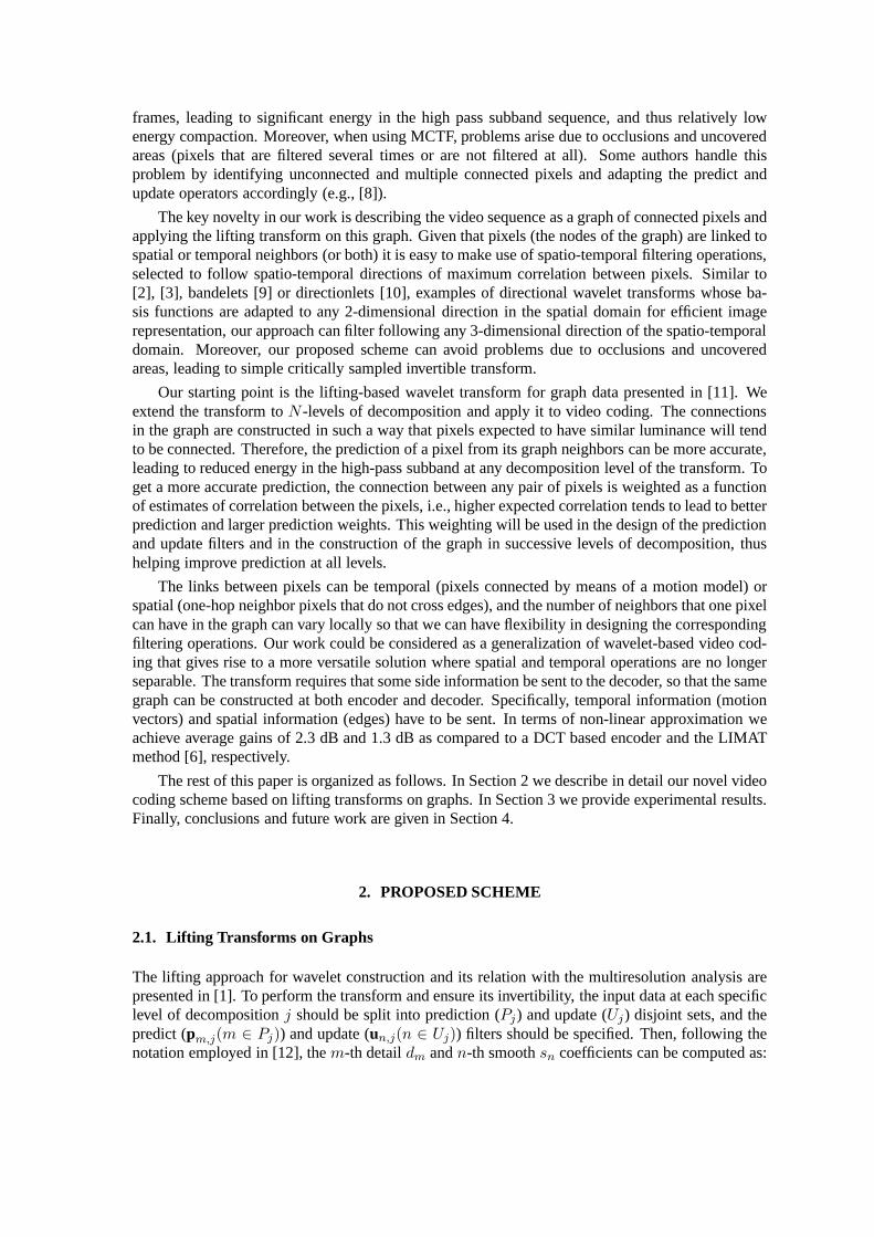
Fig. 3. Graph construction for consecutive levels of decomposition. a = 10, b = 5 andc = 3 arethe different weight values. Grey nodes are update nodes, and white ones are prediction nodes.
The update filter is designed to smooth the next level approximation coefficients as:
un,j =
[
w1p,j w2p,j . . . , wWp,j
]
2(∑Wp
ip=1wip,j)
(3)
where[
w1p,j , w2p,j, . . . , wWp,j
]
are the weights to be applied to the neighbors{1p, 2p, ...Wp} ∈ Pj
of an update pixeln ∈ Uj .
2.4. The transform in higher levels of decomposition
In order to carry out a multiresolution analysis, the low pass coefficients are successively projectedin different transformation levels onto smooth and detail subspaces. To obtain the graph at trans-formation levelj from the graph at levelj − 1, we connect those update nodes that are directlyconnected or at one-hop of distance in the graph at levelj − 1, so that the simplified graph con-tinues to capture the correlation between pixels. In the newgraph inj, the weight between nodeswill be the average of the weights in the path between connected nodes at levelj − 1, so that high-correlation paths at levelj − 1 imply high weight links at levelj. Once we construct the graph atlevel j, we should split the nodes again into prediction (Pj ) and update (Uj) disjoint sets in order toperform the transform. Figure 3 shows an example of a graph construction at levelj from a graphat levelj − 1, and the update-predict assignment at both transformationlevels.
3. EXPERIMENTAL RESULTS
In order to evaluate the performance of our approach, we willemploy theK term non-linear ap-proximation (outlined in [10]). It consists of keeping theK largest coefficients of the transform andsetting the rest to zero. This is a good indicator of energy compaction and thus of coding perfor-mance. We compute the average PSNR of each sequence ofV = 100 frames as a function of thepercentage of retained coefficients.
In our experiments, five levels of decomposition of the proposed transform are performed on theconstructed graphs. Our method is compared to the Haar version of the MCTF approach described in[6] (the LIMAT method), and to a motion-compensated discrete cosine transform (DCT) video coder
10 20 30 40 25
30
35
40
45
50
55N−Term Approximation
Percentage of Coefficients Retained
PS
NR
10 20 30 40 36
38
40
42
44
46
48
50
52N−Term Approximation
Percentage of Coefficients Retained
PS
NR
proposedDCTLIMAT
ProposedDCTLIMAT
Carphone
Mobile
Foreman
Fig. 4. PSNR versus percentage of retained coefficients.
in which a residual image, obtained after block motion estimation and compensation processes,is transformed by a8 × 8 DCT; this scheme is the basis of the latest video coding standards asH.264/AV C.
Side information is not taken into account in the results. Inthe proposed method, we will havean overhead associated with the temporal and spatial information needed to construct the graph atthe decoder. Regarding the temporal overhead, the same motion model is employed inall comparedmethods, i.e., a standard motion vector on8×8 pixel blocks is assumed (only one reference frame),and thus this overhead does not need to be considered in the comparison. As for the spatial informa-tion overhead, we chooseF = 20 and assume a binary edge map (obtained using Roberts’ gradientoperators) is sent to the decoder once everyF frames, so that the spatial side information will bevery low 1. Since this overhead is very small it is not considered in ourcurrent version of the work.Note that there exists a trade-off between graph accuracy and the side information needed constructthe graph. Higher rate to describe the spatial and temporal information (e.g., very small block sizesfor motion), means that the correlation between linked pixels is also better captured by the graph,leading to potential compression gains. The weights used inthe experiments aret = 10 ands = 2,following the reasoning that temporal prediction is more accurate (and costly in bits) than the spatialone. Finally, note that, for simplicity, in the current version only the two more reliables neighbors ofeach pixel are used for filtering and to construct the graphs at the different levels of decomposition.We plan to further investigate alternative filter and graph design approaches in follow up work.
Figure 4 shows the PSNR versus percentage of retained coefficients of three differentQCIFsequences,Mobile, Carphone andForeman. Our proposed method outperforms the DCT basedand the LIMAT transforms in terms of PSNR. In theMobile sequence, when 40 percent of coeffi-cients are retained, our method is 7 dB and 4 dB better than theDCT and the LIMAT respectively.However, the LIMAT method is better than the proposed when a very small percentage of coeffi-cients are retained inMobile. One posible reason could be to have chosen spatio-temporalfilteringdirections worse than the temporal ones chosen by the LIMAT.This problem could be fixed by usingmore accurate metrics to weight the graph.
For subjective evaluation, Figure 5 shows the original of the frame number 12 of the sequenceMobile (upper-left part) and the reconstruction from the DCT transform on the residual (upper-right part), the LIMAT approach (lower-left part) and the proposed method (lower-right part). The
1For example, with JBIG compression of edge maps as used in [2]rates of the order of 0.02 bits per pixelare required every20 frames, so that the overall overhead is negligible,0.001 bits per pixel overall
reconstruction is carried out from the 20 % of retained coefficients. It can be shown that our trans-form achieves significant better perceptual quality than the DCT, and slight improvements over theLIMAT method (see for example the three animals of the upper-left part of the frames).
Fig. 5. Original (upper-left) and reconstruction with 20 % of the transform coefficients from theDCT on the residual image (upper-right), LIMAT (lower-left) and our proposed method (lower-right).
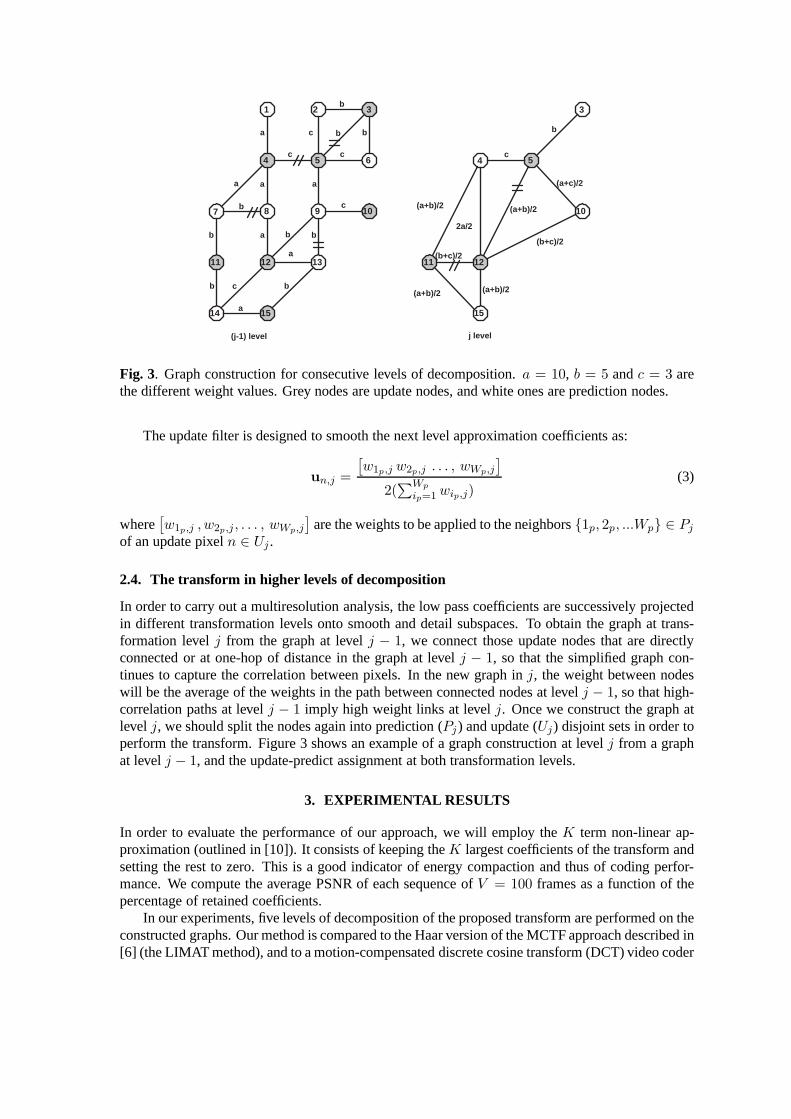
3.1. Performance in uncovered areas
To further explain the advantages of our proposed scheme we now consider in more detail situationsinvolving uncovered areas. Refer to Figure 6, where we show the motion mappings used by theHaar version of the LIMAT approach with two levels of decomposition. Prediction frames (P) willbe filtering following the directions indicated by the MV, and update frames (U) will be updatedusing inverse mappings MV−1. Grey pixels represent non-updated pixels in thej − 1 level ofdecomposition, that is, pixels that have not been low-pass filtered and thus contain high frequencyenergy. This high frequency will not be removed using the smooth coefficients atj level, givingrise to inefficiency. The black pixel represents a pixel thathas not been decorrelated at any level, sothat the coefficient after both levels of decomposition willbe the raw pixel. The proposed methodcan solve this problem by representing video information asa graph (Figure 2) leading to a versatileprediction-update assignment, in which prediction and update nodes can belong to the same frame.To show this statement we have encoded two different32×32 pixel areas of the sequence Foreman.Area 1 starts at pixel (1,1), so that could be considered a fairly static area. Area 2 starts at pixel(80,80), corresponding to a very dynamic area (the face of the man). The results in terms of PSNRwhen saving the 20 % of the coefficients are preserved are given in Table 1. Our proposed method
P U P U
U P
MV
MV
MV
MV -1 MV
-1
MV -1
(J-1) level
J level
Fig. 6. Uncovered areas in LIMAT.
Table 1. Comparison of LIMAT and the proposed transform coding different areasPSNR(dB) in Area 1 PSNR(dB) in Area 2
Proposed 43.1 36LIMAT 42.4 33.3
∆ 0.7 2.7
obtains slightly better results than the LIMAT in Area 1, while significantly outperforming LIMATin Area 2, where there is a lot of motion and the uncovered background problem manifests itself.
4. CONCLUSIONS AND FUTURE WORK
We have proposed a directional lifting wavelet transform that is able to filter along 3 dimensionalspatio-temporal directions of high correlation between pixels, leading to a compact representationof the data with low energy in the high frequencies. The results in terms ofK-term non linearapproximations are very promising. However, quantized transform coefficients should be encodedas compactly as possible to obtain an efficient real encoder.We are currently investigating how touse the graph information in the decoder to group together nonzero coefficients. Another interestingfuture line of research would be to design a low-complexity version of the transform that works withsub-graphs formed from the original graph without loss of performance.
Acknowledgments
The authors thank Sunil K Narang and Godwin Shen for the code to implement the prediction-update assignment and the lifting in graphs.
5. REFERENCES
[1] Wim Sweldens, “The lifting scheme: A construction of second generation wavelets,” Tech.report 1995:6, Industrial Math. Initiative, Dept. of Math., University of South Carolina, 1995.
[2] G. Shen and A. Ortega, “Compact image representation using wavelet lifting along arbitrarytrees,” inImage Processing, 2008. ICIP 2008. 15th IEEE InternationalConference on, Octo-ber 2008, pp. 2808 –2811.
[3] G. Shen and A. Ortega, “Tree-based wavelets for image coding: Orthogonalization and treeselection,” inPicture Coding Symposium, 2009. PCS 2009, May 2009, pp. 1 –4.
[4] Raanan Fattal, “Edge-avoiding wavelets and their applications,” inSIGGRAPH ’09: ACMSIGGRAPH 2009 papers, New York, NY, USA, 2009, pp. 1–10, ACM.
[5] N. Adami, A. Signoroni, and R. Leonardi, “State-of-the-art and trends in scalable video com-pression with wavelet-based approaches,”Circuits and Systems for Video Technology, IEEETransactions on, vol. 17, no. 9, pp. 1238 –1255, September 2007.
[6] A. Secker and D. Taubman, “Lifting-based invertible motion adaptive transform (limat) frame-work for highly scalable video compression,”Image Processing, IEEE Transactions on, vol.12, no. 12, pp. 1530 – 1542, December 2003.
[7] Gregoire Pau, Christophe Tillier, Batrice Pesquet-Popescu, and Henk Heijmans, “Motioncompensation and scalability in lifting-based video coding,” Signal Processing: Image Com-munication, vol. 19, no. 7, pp. 577 – 600, 2004, Special Issue on Subband/Wavelet InterframeVideo Coding.
[8] B. Pesquet-Popescu and V. Bottreau, “Three-dimensional lifting schemes for motion com-pensated video compression,” inICASSP ’01: Proceedings of the Acoustics, Speech, andSignal Processing, 2001. on IEEE International Conference, Washington, DC, USA, 2001,pp. 1793–1796.
[9] E. Le Pennec and S. Mallat, “Sparse geometric image representations with bandelets,”ImageProcessing, IEEE Transactions on, vol. 14, no. 4, pp. 423 –438, April 2005.
[10] V. Velisavljevic, B. Beferull-Lozano, M. Vetterli, and P.L. Dragotti, “Directionlets: anisotropicmultidirectional representation with separable filtering,” Image Processing, IEEE Transac-tions on, vol. 15, no. 7, pp. 1916 –1933, July 2006.
[11] Sunil K. Narang and A. Ortega, “Lifting based wavelet transforms on graphs,” inAPSIPAASC 2009: Asia-Pacific Signal and Information Processing Association, 2009 Annual Summitand Conference, October 2009.
[12] Godwin Shen and A. Ortega, “Optimized distributed 2d transforms for irregularly sampledsensor network grids using wavelet lifting,” inAcoustics, Speech and Signal Processing, 2008.ICASSP 2008. IEEE International Conference on, March 2008, pp. 2513 –2516.
[13] Chi-Ping Hsu, “Minimum-via topological routing,”Computer-Aided Design of IntegratedCircuits and Systems, IEEE Transactions on, vol. 2, no. 4, pp. 235 – 246, 1983.
[14] S.K. Narang, G. Shen, and A. Ortega, “Unidirectional graph-based wavelet transforms for effi-cient data gathering in sensor networks,” inAcoustics Speech and Signal Processing (ICASSP),2010 IEEE International Conference on, 2010, pp. 2902 –2905.


![FACTORING WAVELET TRANSFORMS INTO LIFTING STEPSjskang/files/factor.pdf · represent general functions [13, 18, 22, 34, 21]. In the mid eighties the introduction of multiresolution](https://static.documents.pub/doc/80x56/5f7eb90eaaaa8966a861c7b5/factoring-wavelet-transforms-into-lifting-steps-jskangfiles-represent-general.jpg)


