998 JOURNAL OF THE OPTICAL SOCIETY OF AMERICA VOLUME 62, NUMBER 8 Light Absorption in the Bee Photoreceptor ALLAN W. SNYDER AND COLIN PASX* Department of Applied Mathematics, Research School of Physical Sciences, Institute of Advanced Studies, Australian National University, P. 0. Box 4, Canberra 2600, A ustralia (Received 8 February 1972) Photodetection by the individual rhabdomeres of the worker-bee photoreceptor (rhabdom) is analyzed by use of electromagnetic theory. The analysis takes full account of the rhabdom's anisotropic absorption properties. We find, by coupled-mode theory, that only certain modes of a lossless symmetric rhabdom are stable on the lossy rhabdom. Furthermore, the fine structure of the rhabdom (a) enhances the detection of certain modes, whereas it discriminates against others, (b) acts as a polarization detection mechanism, and (c) provides information about the direction of incoming light. INDEX HEADINGS: Vision; Fibers; Optics; Detectors; Resonant modes. In order to understand completely the process of vision, it is necessary to have a detailed description of light absorption in the visual photoreceptor. Light propaga- tion in a large class of these photoreceptors is known both theoretically' and experimentally 2 ' 3 to be in the form of electromagnetic modes due to the small receptor cross section. One consequence of this small cross sec- tion is that it can alter the receptor absorption spectrum from that of its photopigment.A Other effects are dis- cussed elsewhere. 2 5' 6 In general, the presence of an absorbing pigment within a narrow cylindrical dielectric rod complicates the mathematical description of light propagation. 7 The situation is further complicated in photoreceptors like that of the bee, which are not only lossy but also grossly anisotropic.A The intent of this paper is to develop the mathe- matical techniques for determining light absorption in the worker-bee photoreceptor (rhabdom) from elec- tronhagnetic theory. We begin by finding the modes of the rhabdom and then we use these modes for the analysis of absorption. Because the worker-bee photoreceptor is anisotropic, the mathematical analysis is necessarily involved. We have therefore presented all the results of interest to the biologist in the sections entitled bee rhabdom, dis- cussion, and conclusion, which can be read as a co- herent whole without reference to the mathematical derivations. BEE RHABDOM Photodetection within the bee takes place in long narrow cylinders known as rhabdoms. 3 ' 5 Figure 1 is a schematic cross section of the worker-bee rhabdom. The rhabdom is approximately 4 Arm in diameter, 350 ,um in length, and has an index of refraction (nls1.347) slightly greater than that of its surround (n 2 -1.339). The photopigment is localized in tightly packed tubules known as microvilli, represented by the parallel dark lines of Fig. 1. Each quadrant is made up of two rhabdomeres, numbered 1 to 8. A rhabdomere is an outgrowth of the retinular cell that senses the absorbed light. Owing to the microvilli arrangement, light ab- sorption is polarization sensitive, i.e., more light is absorbed if the electric-field vector is parallel to the microvilli than if it is perpendicular.' 9 The maximum absorption coefficient' 0 is approximately 1.8%/4im. Vol. 62 AUGUST 1972
Transcript
998
JOURNAL OF THE OPTICAL SOCIETY OF AMERICA VOLUME 62, NUMBER 8
Light Absorption in the Bee Photoreceptor
ALLAN W. SNYDER AND COLIN PASX*Department of Applied Mathematics, Research School of Physical Sciences, Institute of Advanced Studies,
Australian National University, P. 0. Box 4, Canberra 2600, A ustralia(Received 8 February 1972)
Photodetection by the individual rhabdomeres of the worker-bee photoreceptor (rhabdom) is analyzedby use of electromagnetic theory. The analysis takes full account of the rhabdom's anisotropic absorptionproperties. We find, by coupled-mode theory, that only certain modes of a lossless symmetric rhabdom arestable on the lossy rhabdom. Furthermore, the fine structure of the rhabdom (a) enhances the detection ofcertain modes, whereas it discriminates against others, (b) acts as a polarization detection mechanism, and(c) provides information about the direction of incoming light.
INDEX HEADINGS: Vision; Fibers; Optics; Detectors; Resonant modes.
In order to understand completely the process of vision,it is necessary to have a detailed description of lightabsorption in the visual photoreceptor. Light propaga-tion in a large class of these photoreceptors is knownboth theoretically' and experimentally2' 3 to be in theform of electromagnetic modes due to the small receptorcross section. One consequence of this small cross sec-tion is that it can alter the receptor absorption spectrumfrom that of its photopigment.A Other effects are dis-cussed elsewhere. 2 5'6
In general, the presence of an absorbing pigmentwithin a narrow cylindrical dielectric rod complicatesthe mathematical description of light propagation.7 Thesituation is further complicated in photoreceptors likethat of the bee, which are not only lossy but alsogrossly anisotropic.A
The intent of this paper is to develop the mathe-matical techniques for determining light absorption inthe worker-bee photoreceptor (rhabdom) from elec-tronhagnetic theory. We begin by finding the modes ofthe rhabdom and then we use these modes for theanalysis of absorption.
Because the worker-bee photoreceptor is anisotropic,the mathematical analysis is necessarily involved. We
have therefore presented all the results of interest tothe biologist in the sections entitled bee rhabdom, dis-cussion, and conclusion, which can be read as a co-herent whole without reference to the mathematicalderivations.
BEE RHABDOM
Photodetection within the bee takes place in longnarrow cylinders known as rhabdoms. 3'5 Figure 1 is aschematic cross section of the worker-bee rhabdom.The rhabdom is approximately 4 Arm in diameter, 350,um in length, and has an index of refraction (nls1.347)slightly greater than that of its surround (n2 -1.339).The photopigment is localized in tightly packed tubulesknown as microvilli, represented by the parallel darklines of Fig. 1. Each quadrant is made up of tworhabdomeres, numbered 1 to 8. A rhabdomere is anoutgrowth of the retinular cell that senses the absorbedlight. Owing to the microvilli arrangement, light ab-sorption is polarization sensitive, i.e., more light isabsorbed if the electric-field vector is parallel to themicrovilli than if it is perpendicular.' 9 The maximumabsorption coefficient'0 is approximately 1.8%/4im.
Vol. 62
AUGUST 1972
LIGHT ABSORPTION IN BEE PHOTORECEPTOR
MATHEMATICAL FORMULATION
We wish to calculate the light absorbed by eachretinular cell of Fig. 1. To do this requires knowing themodes on a lossy anisotropic cylinder, i.e., a cylinderthat has a tensoral index of refraction. These modes arein general very complicated. Instead, we prefer to con-sider the simpler modes of the lossless isotropic struc-ture. However, they do not individually satisfy Max-well's equations for the rhabdom and hence couple orexchange energy as they propagate. The situation isanalogous to expanding a function in terms of a com-plete set of eigenfunctions that individually do notsatisfy the boundary conditions.
A very general method of formulating electromag-netic-wave propagation in a cylindrical medium by aset of linear first-order coupled differential equationsis presented elsewhere.7 Here we make use of the resultsof this coupled-mode formulation for the situation ofsmall index-of-refraction difference between the rhab-dom and its surround, known to exist for the beerhabdom.3 The transverse electric field Et on the rhab-dom is constructed from a superposition of the trans-verse electric modal fields e , of a lossless rhabdom,
E,(x,yz) =F a1, (z)e ,(x,y), (1)
where the summation is over all modes p. Positive(negative) p represents forward (backward) z-propagat-ing modes, respectively. The summation is understoodto extend to an integral for the continuous modes."ep is a normalized electric modal vector, satisfying
where A represents the infinite (x,y) cross-section area,6p. is the Kronecker a function, Ei is the dielectricconstant of the lossless rhabdom, and , is the perme-ability of vacuum. Owing to the orthonormality of themodal fields, the total modal power, P, on the rhabdomat position z is
(3)
so that the total power, P(L), absorbed by the entirerhabdom of length L is
P(L) =P(O) -P(L). (4)
The modal coefficients a, are found from the solu-tion of the coupled mode equations7
da,+iqpap=-E 49Cp9Y
diz q
where 3, is the pth modal propagationcoupling coefficients are
(5)
constant. The
cp==- Vi ",e -e, dA,2 J
(6)
where X is the angular frequency and V' is the imaginarypart of the dielectric constant of the photoreceptormedium. To account for the anisotropic nature of theabsorption, V' is a tensor
if/ = (-I" (X) [ en'" (0) ii + !im (q0) ii, (7)
( ) IX e q e dA= 6pq
y
3 - 2
4 1
6
5w
6
-8
Fio. 1. Schematic representation of the cross section of aworker-bee rhabdom, based on electron microscopy of Varela andPorter (Ref. 8). Each quadrant is made up of two rhabdomeres,which are numbered I to 8. The photopigment is held within theparallel dark lines known as the microvilli. Each rhabdomere is anoutgrowth of a retinular cell, which senses the absorbed light.
where e" (X) is related to the wavelength dependence of(2) the absorbing material within the photoreceptor, i and
i are unit vectors in the x and y directions, respectively.e"(0) and e,"(0) take account of the microvildi ar-rangement and q5 is the azimuthal angle.
For the rhabdom oriented as in Fig. 1, e.," and E1,/' are
ei"n(/) =31, e(,) (</ = ad
in -7r/4 < (0-n1r)<wr/4, and
evil(10) = 1, 'E."(0) = Ed
(8)
(9)
in r/4< (X-ngr)<37r/4, where n is either zero or unityand Ed is a constant that depends on the dicroic (polari-zation) sensitivity of the medium. We have assumed forsimplicity that each rhabdomere has identical absorp-tion properties, because there is no evidence to thecontrary for the worker bee. The rhabdomeres of thedrone rhabdom do not have identical absorptionproperties. 12 a If this is true of the worker, our analysisis only strictly valid for wavelengths at which thespectral sensitivities are similar.
Modes of Lossless Bee Rhabdom
The modes that can propagate along the lossless(fully bleached) bee rhabdom are illustrated in Fig. 2.3
l A- - i t
August 1972 999
PW = T I ap(Z) � 1,
A. W. SNYDER AND C. PASK
EVEN SYMMETRY
/1fl3)
1,2
V3.F5520
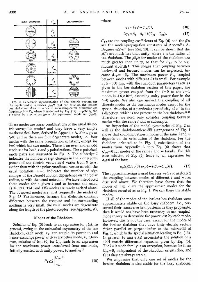
FIG. 2. Schematic representation of the electric vectors forthe x-polarized 1, mn modes (el,.,) that can exist on the losslessbee rhabdom taken in order of increasing-cutoff dimensionlessfrequency V= V4, where V is defined by Eq. (17). Replacing thex vector by a y vector gives the y-polarized mode set (ez,,").
These modes are linear combinations of the usual dielec-tric-waveguide modes' and they have a very simplemathematical form, derived in Appendix A. For a given
#0O and m there are four degenerate modes, i.e., fourmodes with the same propagation constant, except for1=0 which has two modes. There is an even and an oddmode set for both x and y polarizations. The x-polarizedmode pairs are illustrated in Fig. 2. The subscript Iindicates the number of sign changes in the x or y com-ponent of the electric vector as 4) varies from 0 to 7r,rather than with the polar coordinate vector as with theusual notation. m-1 indicates the number of signchanges of the Bessel-function dependence on the polarradius, as with the usual notation.' We have introducedthese modes for a given I and m because the usual(HE, EH, TM, and TE) modes are rarely excited alone.The observed modes are most frequently the modes ofFig. 2.3 Furthermore, because the dielectric-constantdifference between the receptor and its surroundingmedium is very small, the usual modes are degeneratealong the length of the photoreceptor (see Appendix A).
Modes of the Rhabdom
Solution of Eq. (5) leads to an expression for a(z). Ingeneral, owing to the azimuthal asymmetry of the beerhabdom, each mode, ep, can couple its power to andhence exchange power with every other mode, eq. How-ever, solution of Eq. (6) for Cpq leads to an expressionfor the maximum power transferred from one mode,initially excited with unity power, to another13
PPq , (10)
-
where
'Y b = (7j_-C.2)1 (10)
27d flp-I,+i(Cqq-Cpp) . (12)
Cpq are the coupling coefficients of Eq. (6) and the O3'sare the modal-propagation constants of Appendix A.Because eO>XI" (see Ref. 10), it can be shown that thepC's are much less than unity, where p is the radius ofthe rhabdom. The pp's for modes of the rhabdom aremuch greater than unity, so that for P,, to be sig-nificant jp/s3_-1. This means that coupling betweenbackward and forward modes can be neglected, be-cause 8-l= -f,. The maximum power P1, coupledbetween modes with different l's is small. For exampleat X =300 nm, with the rhabdom parameters taken asgiven in the bee-rhabdom section of this paper, themaximum power coupled from the 1=0 to the 1=1modes is 3.6X10⁻³, assuming unity power flow in the1=0 raode. We also can neglect the coupling of alldiscrete modes to the continuous modes except for thespecial situation of a particular periodicity of E
1 in thez direction, which is not present on the bee rhabdom.1 4"5
Therefore, we need only consider coupling betweenmodes with the same I and in subscripts.
An inspection of the modal symmetries of Fig. 2 aswell as the rhabdom-microvilli arrangement of Fig. 1shows that coupling between modes of the same I and mdepends on the orientation of the rhabdom. For therhabdom oriented as in Fig. 1, substitution of themodes from Appendix A into Eq. (6) shows thatC,,Q=0 for modes of the same I and m family. For thiscase solution of Eq. (5) leads to an expression fora1, (z) of the form
a,(z)_pa,(O) exp(- (ij3 , +C, 1, )z)- (13)
The approximate sign is used because we have neglectedthe coupling between modes of different I and m, asdiscussed above. We therefore have shown that themodes of Fig. 2 are the approximate modes for therhabdom oriented as in Fig. 1. We call these the stablemodes.
If all of the modes of the lossless bee rhabdom wereapproximately stable on the lossy rhabdom, i.e., pre-served their transverse field patterns as they propagate,then it would not have been necessary to use coupled-mode theory to determine the power lost by each mode.However, this is not the case, except for the modes ofthe lossless rhabdom that have their electric vectorseither parallel or perpendicular to the microvilli ofFig. 1, which is the special situation leading to Eq. (13).In general, to find a,(z) necessitates the solution of a4X4 matrix differential equation given by Eq. (5).The 1=0 mode family is an exception, because for themCpq=O, independent of the rhabdom orientation, andthus they are always stable.
We emphasize that only one set of modes for thelossless rhabdom is also stable for the lossy rhabdom.
.
- -
I I
1000 Vol. 62
LIGHT ABSORPTION IN BEE PHOTORECEPTOR
These modes will be called stable modes and, unlessstated otherwise, they are the modes used for the re-mainder of the paper.
The self-coupling coefficient, C,,, is found by sub-stituting the modes of Appendix A into Eq. (16),leading to
FIG. 3. The fraction of modal light within the rhabdom vsdimensionless frequency V defined by Eq. (17). If nI= 1.347 andLn2= 1.339, there are no other modes on the bee rhabdom.
Power Absorbed by the Entire Rhabdom
Knowing C,, allows us to determine the power ab-sorbed by the entire rhabdom, i.e., the sum of allretinular cells. The power lost to a rhabdom of lengthL by the pth stable mode is found from Eq. (4),
2 17r\
C11(X) =U)uIm(1aX) +Ed-z-((1 -Ed) sin-)
1> 1 (14b)
where the upper (lower) sign is for the even x or y odd(odd x or even y) polarized modes. a(X) is the absorptioncoefficient for the photopigment in solution, i.e., theabsorption when the photopigment is not confined tothe narrow cylindrical photoreceptor. a(X) is
a(X)==CO -) el (X)W (15)
The fraction of modal light within the photoreceptoris
(l)lf dA. (16)
Analytic expressions for fljm are derived in Ref. 12.Figure 3 illustrates qlm(V) for the modes of the beerhabdom. V is a dimensionless frequency,
/ 2 irp\
V=t (ni 2- n22)1, (17)
where n, and n2 are the index of refraction for thephotoreceptor and its surrounding medium, respec-tively, and A is the free-space wavelength. From thebee's photoreceptor parameters, 3 p= 2 ,um, nl=1.347and n22= 1.339, X =300-600 nm corresponds to V=6.16to 3.08. We have graphed rj vs V because, for nln 2 ,77m(V) depends on the difference of index of refractionthrough V only.
TABLE I. Absorbed power for individual modes of the beerhabdom assuming a=1.8 X10⁻² /um, L=350 jum, and V=6.16.Each mode is excited with unit power.
Mode type P, (Ed = O) P, (Ed=0.2) P, (Ed = 0.4)1 in Even Odd Even Odd Even Odd
R im
1=0 (14a)
We have assumed that the modal power at z=0 is unity.Specification of the rhabdom parameters and wave-length defines C1, through Eq. (14). We consider theultraviolet region of the spectrum (X-300 nm orV=6.16) where the bees are known to have a high de-gree of polarization sensitivity,'6 so that Ed of Eqs. (8)and (9) is small. Table I presents the absorbed powerfor the modes of the bee rhabdom with an assumedmaximum value of a(X) = 1.8X10- 2/1 1um and L=350um. 310m is found from Fig. 3 for V=6.16. Each mode
has a characteristic absorption. We find that therhabdom structure enhances the absorption of evenx-polarized modes, whereas it discriminates against theodd x-polarized modes. For example, the even 1=1modes absorb 93% while the odd modes absorb 66%of the modal power when Ed=0.2 . Furthermore, theeven 1= 1 mode is best detected by the rhabdom struc-ture in comparison to all other modes. Qualitatively,this is easy to see by superimposing upon Fig. 1 themodal pattern of Fig. 2. The even eiix and odd elly haveelectric fields aligned for maximum absorption whilethe odd euix and even elly modes have their electricfields aligned for poor absorption.
The rhabdom responds to the light absorbed by eachof its eight rhabdomeres. It is not yet known how theoutput of the retinular cells of which the rhabdomeresare a part are summed to give a visual sensation, so thatthe result obtained above is difficult to interpret. How-ever, it is possible to sense experimentally the outputof an individual retinular cell, 9"7 so we next investigatelight absorption by each of the eight rhabdomeres ofFig. 1.
0.8520.436 0.9320.775 0.833
0.8210.808 0.7540.333 0.851
0.6630.833
0.8450.537
0.8920.9400.8760.8640.8230.863
0.7990.876
0.8750.679
CIPW) = (4DOmaO!)(l +Ed),
Pp (L) = 1-exp(-2CppL). (18)
012031
111212
0.9760.9240.7750.7600.6580.839
August 1972 1001
A. W. SNYDER AND C. PAS V
Power Absorbed in an Individual Rhabdomere
We have found the coefficients a(z) for the modal ex-pansion of the electric vector given by Eq. (1) in termsof the stable modes. These coefficients are related to themodal power lost to the entire receptor, as given byEqs. (3) and (4). To find the power lost, p(i), in the ithrhabdomere requires use of the alternative expressionfor power,
rLp(i) ( fL dz f £"Et E,*dA, (19)
o i
where Ai is the ith rhabdomere cross section and L isthe receptor length. Substitution of Et from Eq. (1)into Eq. (19) leads to
P(i) = 2(, ) [1-exp(-2C,,L)]P
+4 Re E Pp,(i), (20)P.qP<q
where bp[bp=ap(O)] is the z-independent modal ampli-tude coefficient found from the excitation conditions,Cp, is defined by Eq. (14), Re is the real part, andPpq(i) is
p (i) bb*C((i) --Pq - e (CP P+C"') 2+ (,3P_, )2
X { 1-exp(-Ei(1p-13q)+Cpp+Cq]L)), (21)
where Cpq(i) is
roCpq i)=- J " tep -edA. (22)
2 4
When modes p and q are of unlike 1,
p-fq I»>> (Cpp+Cqq)
and, unless CppL<<K, the cross-mode coupling betweenthese modes can be neglected, because Cpq«(i)<< I3 p,-q I .Therefore, the major contribution of Eq. (21) is frommodes of like 1, leading to
Ppq(i) bpbq*( ()
X[1-exp(-(Cpp+Cqq)L)]. (23)
Equations (20) and (23) provide the general ex-pressions for the light absorbed by a retinular cell ofFig. 1.
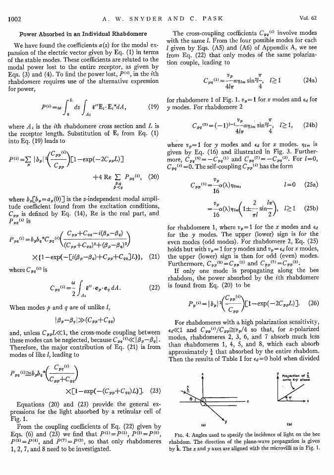
From the coupling coefficients of Eq. (22) given byEqs. (6) and (23) we find that p(1)=p(5), p(2)=p(6),
p(8)=P(4), and p( 7 )=p(3 ), so that only rhabdomeres1, 2, 7, and 8 need to be investigated.
The cross-coupling coefficients Cpq(i) involve modeswith the same 1. From the four possible modes for eachI given by Eqs. (A5) and (A6) of Appendix A, we seefrom Eq. (22) that only modes of the same polariza-tion couple, leading to
VP 4Cp()=-a-q.lmi 2-
41wr 41>1 (24a)
for rhabdomere 1 of Fig. 1. vp= 1 for x modes and Ed fory modes. For rhabdomere 2
VPCpq(2)=(-l)1-1-aqim sin21-, 1>1, (24b)
41r 4
where vp=1 for y modes and ed for x modes. 77im isgiven by Eq. (16) and illustrated in Fig. 3. Further-more, Cp,(8) = -Cp q(l) and Cpq(7) = Cpq(2). For 1=0,Cpq(i) =0. The self-coupling CppMi) has the form
VP
16
VP / 2 Ir\=-at(X)7im(1h sin- ,
16 wir 2/
1=0 (25a)
1>1 (25b)
for rhabdomere 1, where vp = 1 for the x modes and edfor the y modes. The upper (lower) sign is for theeven modes (odd modes). For rhabdomere 2, Eq. (25)holds but with vp = 1 for y modes and Vp= Ed for x modes,the upper (lower) sign is then for odd (even) modes.Furthermore, Cpp(8) =Cpp(l) and CPP(7)=Cpp(2).
If only one mode is propagating along the beerhabdom, the power absorbed by the ith rhabdomereis found from Eq. (20) to be
PP(i) =I bPi 2( )[1-exp(-2CppL)]. (26)
For rhabdomeres with a high polarization sensitivity,ed<<l and Cpp(i)/cpp-vp/4 so that, for x-polarizedmodes, rhabdomeres 2, 3, 6, and 7 absorb much lessthan rhabdomeres 1, 4, 5, and 8, which each absorbapproximately ' that absorbed by the entire rhabdom.Then the results of Table I for Ed=0 hold when divided
XA Projection of kj i jonto X-y plane
e 1'z Ht ,x
Ca) tb)
FIG. 4. Angles used to specify the incidence of light on the beerhabdom. The direction of the plane-wave propagation is givenby k. The x and y axes are aligned with the microvilli as in Fig. 1.
Vol. 621002
LIGHT ABSORPTION IN BEE PHOTORECEPTOR
by 4. For y-polarized modes, the roles of the two groupsof rhabdoms are interchanged. Thus, we find that theindividual rhabdomeres, like the entire rhabdom, detectcertain modes better than others.
When more than one mode propagates, the expressionfor power involves the cross terms, P,,(i). To study thepower absorbed when more than one mode is presentrequires knowing the br's and hence solving the ex-citation problems.
For an arbitrary illumination by an incident electricfield, Ejnc the modal coefficients b,, arel8
bp= E ine'e, dA. (27)A
We can therefore find the power absorbed in the in-dividual rhabdomeres for an arbitrary excitation givenby Ein,.
EXCITATION OF MODES ON BEE RHABDOM
We now consider the illumination of the photo-receptor by a beam of coherent light centered on theend of the rhabdom and at an arbitrary angle of in-cidence. The beam has an approximate radius equal tothe bee-rhabdom radius p. This illumination approxi-mates the dioptric apparatus of the bee for very smallangles of incidence.6
The incident-beam direction, i.e., the wave vectorlk, is specified by two angles, 0 and VI (see Fig. 4). Weare interested in nearly normal incidence, so 0 is small,but the azimuthal angle 4' may vary from 0 to 2r.The polarization vector ELn, of the beam is perpen-dicular to k and so for small 0, EL,, may lie anywherein the xy plane. We let Ei,,, have azimuthal angle Oo, so
Ei,,,= costot+sin95oo (28)and
Ejnc= E1nce-0 'r (29)
In order to carry out a modal analysis for this input,we need to find the excitation coefficients b, defined byEq. (27). A similar problem has already been solved'8
by consideration of the lossless modes excited for thet=0 case. Our general case is related to that specialone and analysis gives for 1=0
b,=cos5,Bo,,4, i mode
=sinq0oBom, 9 mode (30a)
and for 1> 1
bP=cos0o cos(l4)Bzm, x even mode= cos§5, sin (41)Bim, X odd mode
=sink, cos(Af)Bim, 9 even mode
=sin¢i, sin(*)Bzm, 9 odd mode (30b)
where B,,,, is the modal excitation coefficient for the
lossless modes of the bee rhabdom found in Ref. 18-Reference 18 gives numerical values not for Bim, butfor modal power, i.e., BlmBim*. However, in the lastsection we showed that when the power absorbed is ob-tained by use of Eq. (20), it is only necessary to knowBpBQ* when p and q are modes with the same 1. Thus,we require BI.nBzmt*. In most cases, we only needBB,* when p and q are modes with the same I and m;then RimEB ,, is a common factor and the results' 8 canbe incorporated directly into the present case.
Depending on wavelength and angle of incidence, theincident plane wave Eq. (29) excites an arbitrary num-ber of modes. At any given frequency and angle ofincidence 0<<1, Fig. 3 in Ref. 18 shows that the domin-ant modes are 1=0 and 1=1 modes with m=1. Theexperimental results of Varela and and Wiitanen' forthe honeybee also indicate that these are the dominantmodes; so, for the examples of this paper, we retainonly the 1=0, m=1 and 1=1, n=1 modes. Underthese circumstances, the power absorbed in rhabdomerei can be obtained from Eq. (20) as
(31)
Note that Bim depends on 0, whereas Qim(i) contains the4', 0o dependence and the effects of loss and mode mix-ing. Qusi)m is the modal power absorbed when the 1,m set of stable modes is excited with unit power. Qtm_('can also be thought of as the modal power absorbed bya single unstable mode excited with unit power.
For I=0, use of Eq. (20) gives
1 (cos200+qEd sin09o)Q01" =) -Qol i (0) =---
4 I+Ed
Xwher i= I lr (32)where i = 1 or 8. Also
Q91(o (7g) =Qo(2) (0c) =Qoi') (0oir/2). (33)
D[e recall here that after Eq. (23) we deduced thatp()=p5) P (2 )=p(), p(8) =P(4
), and P(Y)=P0). TheQ's are similarly related, so again only rhabdomeres 1,2, 7, and 8 need be investigated.]
From Fig. 3 of Ref. 18, we see that only the 1=0,m=1 mode is efficiently excited for light very nearnormal incidence on the rhabdom (0=0) and that itspower is nearly unity. Thus the above equations pro-vide an expression for the power absorbed in eachrhabdomere for that illumination condition.
For I=m= 1 modes, the situation is more complex,with Qi(i) being a function of 90 and A'. The completeanalytical expressions are given in Appendix B. Somesample results are presented in Figs. 5 and 6. Theseresults compare the power absorbed in rhabdomeres 1and 2 as the polarization vector rotates through 90°(i.e., q0 varies from 0 to ir/2), for a comprehensive setof values for the excitation azimuthal angle 4' withed=0.2. The curves show clearly that the rhabdomeres
August 1972 10)03
Pw= I Bo, �'Qoll"+ I Bill IQ1110.
A. W. SNYDER AND C. PASK
01)Q-
.3-
.2 -
0 -l0
m = 1
: =P.1
'0
.3 -
,2 -
.1 -
(i)
.3
.2
.3-
.2-
,1
I = 1m=1 .3-
.2 -
.1 -
D11A_lo
- -- - - a
o 'c/4 k/2
.3- -
.2-
or . /4 */ * no
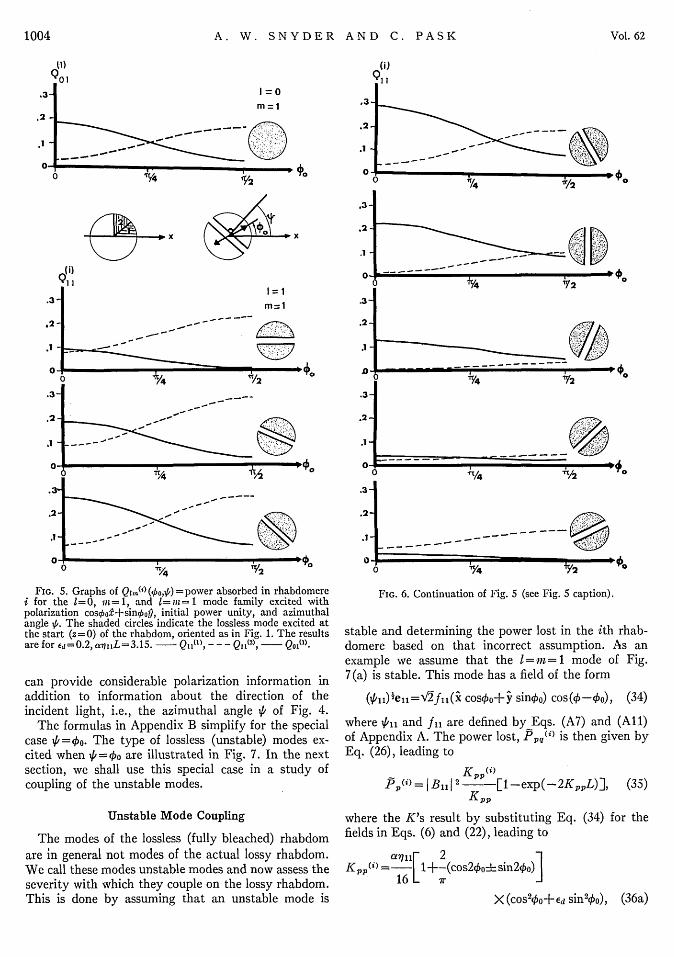
0NFIG. 5. Graphs of Qim(i) ('o,ip) =power absorbed in rhabdomere
i for the 1=0, iin=1, and 1=I-i=1 mode family excited withpolarization cos4oo+sinkop, initial power unity, and azimuthalangle 5,. The shaded circles indicate the lossless mode excited atthe start (z=O) of the rhabdom, oriented as in Fig. 1. The resultsare for Ed=0.2, aq i L=3.15. - Q1I('), - - - Q11(2), Q 0 (l).
can provide considerable polarization information inaddition to information about the direction of theincident light, i.e., the azimuthal angle \6 of Fig. 4.
The formulas in Appendix B simplify for the specialcase VI=Oo. The type of lossless (unstable) modes ex-cited when 'k=Oo are illustrated in Fig. 7. In the nextsection, we shall use this special case in a study ofcoupling of the unstable modes.
Unstable Mode Coupling
The modes of the lossless (fully bleached) rhabdomare in general not modes of the actual lossy rhabdom.We call these modes unstable modes and now assess theseverity with which they couple on the lossy rhabdom.This is done by assuming that an unstable mode is
.3 -
.2-
.12
I 'Y4 '2
-------- - - - -½
6 1/4 A/2 c
.3
0 *e
T0
FIG. 6. Continuation of Fig. 5 (see Fig. 5 caption).
stable and determining the power lost in the ith rhab-
domere based on that incorrect assumption. As anexample we assume that the I= m = 1 mode of Fig.
where Xi,6 and fil are defined by Eqs. (A7) and (All)of Appendix A. The power lost, Ppq(i) is then given by
Eq. (26), leading to
PP(i)= jB11J 2 [1-exp(-2KppL)], (35)Kpp
where the K's result by substituting Eq. (34) for the
fields in Eqs. (6) and (22), leading to
a7lly 2 1Kpp(i) = 1 +-(cos2poo sin2ko)I
16 L (36a
X(COS'co+'Ed sin2 oo), (36a)
- He
-^
1004 Vol. 62
1/4
I-- - __ - - - - - - - - - Z
Io
rh --0. X�1_j
LIGHT ABSORPTION IN BEE PHOTORECEPTOR
where1.6
and
7T
Kpp (2) (,o) =Kpp(1) -- 0 )2
Kpp(7) (0o) =Kpp(0) 0o--)X2
Kpp 0) (-o) = Kpp I) (-,Oo),
Kpp = -1 + Ed+-( 1-'Ed) COS22002
(36b)
(36c)
(36d)
(36e)
1.0
0.8
2 4
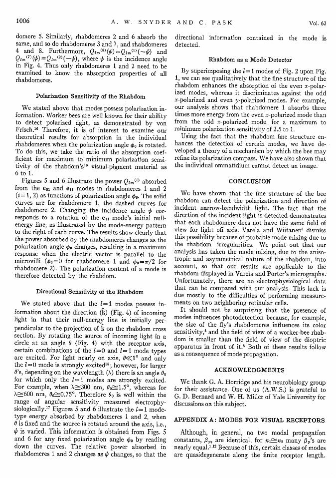
The correct modal power loss, P('), for this unstablemode is the sum of the losses of each of the four modesof Fig. 7(b) and is found from Eq. (31) with Boi=0.Figure 8 shows, for rhabdomere 1, the ratio P(')/P(l)(ratio of modal loss, assuming that the unstable modeis stable to the correct answer for loss), as a function ofthe polarization angle 40. When the electric vector isparallel or perpendicular to the microvilli, 4o=0,47r/2 and the unstable mode is stable. We see fromFig. 8 that the ratio at these values of Oo is unity.However, it is clear from the figure that, in general,considerable error results (60% for Ed=0 and 30% forEd=0.2) from not using the stable mode, so that modecoupling is significant between the lossless modes ofthose like I and m on the bee rhabdom.
LOSSLESS MODES
POWER t Z-
( f I
(a)
STABLE LoSSY MODES
POWER
a oi~ I oIl
(9 I 24|o
£-12 4 sWn24* 1|
24,, 2 t ln B 2
(b)
FIG. 7. 1=0, mn=1 and 1=1, in=1 modes excited by the planewave of Eq. (29) with p=oo. (a) illustrates the lossless mode ex-cited, whereas (b) illustrates the combination of stable modesexcited. As stated in earlier sections, the 1=0 lossless modes arestable, so they need not be split into x- and y-polarized modes.
FIG. 8. The ratio of the modal power loss of an unstable mode,assumed stable, to the correct answer for the l= in = 1 modes withP,= o. The solid curve is for Ed=0.
2 , the broken curve for Ed=0.4 .Both curves have a(X)wsi(X)L=3.l5. This figure provides dataon the severity of unstable mode coupling.
DISCUSSION
Light travels along the anisotropic bee rhabdom asmodes. In this paper, these rhabdom modes are calledstable modes to distinguish them from the modes on alossless (fully bleached) rod of the same dimensions andrefractive index as the rhabdom (modes which ingeneral are not rhabdom modes). We find that particularmodes of the lossless rod are also rhabdom (or stable)modes; they are shown in Fig. 2, where the coordinatesystem is that of Fig. 1. The arrows represent directionof polarization of the electric field, and in Fig. 2 weshow the x-polarized modes. There are also y-polarizedrhabdom modes, obtained by rotating all the arrows by900. The shaded areas represent regions of high energydensity. For example, the energy of the I=0 mode typehas circular symmetry and is maximum near the centerof the rhabdom, gradually decreasing radially. Theenergy density of the I= 1 mode type has a sinusoidalazimuthal symmetry and radially reaches a maximumat about half the radius of the rhabdom. Appendix Aprovides simple analytic expressions for the modalfields. We restrict our discussion to the e0o and ell modetypes, since they are most frequently observed on thebee rhabdom.
An incident plane wave excites a combination ofI = 0 modes and l= 1 modes. The initial l= 1 mode-typepattern depends on the direction of incidence, becausethe null (or low-energy) line is always perpendicularto the projection of incident light on the rhabdom crosssection-see Fig. 4 and the drawings of Figs. 5 and 6.
Therefore, light propagates along the rhabdom asmodes that contain both polarization and directionalinformation about the incident light. The degree towhich the rhabdomeres can detect this information isfound by determining the power absorbed in each in-dividual rhabdomere.
For the 1, m modes, the power Qrn~') absorbed inrhabdomere 1 is identical to that absorbed in rhab-
August 1972 1005
;D) 1.2
B.,.I'
.i_4+. J.J,|
flD ... 4j. J."12
A. W. SNYDER AND C. PAS V
domere 5. Similarly, rhabdomeres 2 and 6 absorb thesame, and so do rhabdomeres 3 and 7, and rhabdomeres4 and 8. Furthermore, Qzm( 8 (4) =Qlrn(')(-A) andQI m (7)() =Qlm(2)(-O) where V' is the incidence anglein Fig. 4. Thus only rhabdomeres 1 and 2 need to beexamined to know the absorption properties of allrhabdomeres.
Polarization Sensitivity of the Rhabdom
We stated above that modes possess polarization in-formation. Worker bees are well known for their abilityto detect polarized light, as demonstrated by vonFrisch."8 Therefore, it is of interest to examine ourtheoretical results for absorption in the individualrhabdomeres when the polarization angle 0o is rotated.To do this, we take the ratio of the absorption coef-ficient for maximum to minimum polarization sensi-tivity of the rhabdom's'l visual-pigment material as6 to 1.
Figures 5 and 6 illustrate the power Q1m.") absorbedfrom the eo0 and ei1 modes in rhabdomeres I and 2(i= 1, 2) as functions of polarization angle Eo. The solidcurves are for rhabdomere 1, the dashed curves forrhabdomere 2. Changing the incidence angle ,6 cor-responds to a rotation of the ell mode's initial null-energy line, as illustrated by the mode-energy patternto the right of each curve. The results show clearly thatthe power absorbed by the rhabdomeres changes as thepolarization angle 4'o changes, resulting in a maximumresponse when the electric vector is parallel to themicrovilli (0o=0 for rhabdomere 1 and 4o=ir/2 forrhabdomere 2). The polarization content of a mode istherefore detected by the rhabdom.
Directional Sensitivity of the Rhabdom
We stated above that the 1=1 modes possess in-formation about the direction (1) (Fig. 4) of incominglight in that their null-energy line is initially per-pendicular to the projection of k on the rhabdom crosssection. By rotating the source of incoming light in acircle at an angle 0 (Fig. 4) with the receptor axis,certain combinations of the 1=0 and 1=1 mode typesare excited. For light nearly on axis, «<<jO and onlythe 1=0 mode is strongly excited1 8 ; however, for larger0's, depending on the wavelength (X) there is an angle 0ofor which only the 1=1 modes are strongly excited.For example, when X-Ž300 nm, Oo-1.5 0 , whereas forX\-600 nm, a-0.7 50 . Therefore O0 is well within therange of angular sensitivity measured electrophy-siologically.i7 Figures 5 and 6 illustrate the I= 1 mode-type energy absorbed by rhabdomeres 1 and 2, when0 is fixed and the source is rotated around the axis, i.e.,y1 is varied. This information is obtained from Figs. Sand 6 for any fixed polarization angle 4'o by readingdown the curves. The relative power absorbed inrhabdomeres 1 and 2 changes as ,6 changes, so that the
directional information contained in the mode isdetected.
Rhabdom as a Mode Detector
By superimposing the 1= 1 modes of Fig. 2 upon Fig.1, we can see qualitatively that the fine structure of therhabdom enhances the absorption of the even x-polar-ized modes, whereas it discriminates against the oddx-polarized and even y-polarized modes. For example,our analysis shows that rhabdomere 1 absorbs threetimes more energy from the even x-polarized mode thanfrom the odd x-polarized mode, for a maximum tominimum polarization sensitivity of 2.5 to 1.
Using the fact that the rhabdom fine structure en-hances the detection of certain modes, we have de-veloped a theory of a mechanism by which the bee mayrefine its polarization compass. We have also shown thatthe individual ommatidium cannot detect an image.
CONCLUSION
We have shown that the fine structure of the beerhabdom can detect the polarization and direction ofincident narrow-bandwidth light. The fact that thedirection of the incident light is detected demonstratesthat each rhabdomere does not have the same field ofview for light off axis. Varela and Wiitanen3 dismissthis possibility because of probable mode mixing due tothe rhabdom irregularities. We point out that ouranalysis has taken the mode mixing, due to the aniso-tropic and asymmetrical nature of the rhabdom, intoaccount, so that our results are applicable to therhabdom displayed in Varela and Porter's micrographs.Unfortunately, there are no electrophysiological datathat can be compared with our analysis. This lack isdue mostly to the difficulties of performing measure-ments on two neighboring retinular cells.
It should not be surprising that the presence ofmodes influences photodetection because, for example,the size of the fly's rhabdomeres influences its colorsensitivity,4 and the field of view of a worker-bee rhab-dom is smaller than the field of view of the dioptricapparatus in front of it.' Both of these results followas a consequence of mode propagation.
ACKNOWLEDGMENTS
We thank G. A. Horridge and his neurobiology groupfor their assistance. One of us (A.W.S.) is grateful toG. D. Bernard and W. H. Miller of Yale University fordiscussions on this subject.
APPENDIX A: MODES FOR VISUAL RECEPTORS
Although, in general, no two modal propagationconstants, f,,, are identical, for nl-fn2 many fp's arenearly equal.' 12 Because of this, certain classes of modesare quasidegenerate along the finite receptor length.
1006 Vol. 62
LIGHT ABSORPTION IN BEE PHOTORECEPTOR
Here, we consider the simplest linear combinations ofthese quasidegenerate modes.
A simplified set of modes and eigenvalues for thecase of small dielectric difference between a cylinderand its surrounding medium has been derived.' 2 Weuse these modes to construct general solutions toMaxwell's equations for a cylindrical dielectric structure
(Al)
where E is the transverse electric field vector, e, is thetransverse orthonormal field of the pth mode, and f,is the pth modal propagation constant. The modalfields are normalized as in Eq. (2).
The simplified modal fields for the even and oddazimuthal HEm and EHtm modes are given by Eq.(77a) of Ref. 12. For each set of I and m there are fourmodes. The TMom modes are the EHom even modes andthe TEom modes are the EHom odd modes. We now con-sider the linear combination (sum and difference) ofthe even HEim and even EHl-2 ,m modes, multiplied bytheir appropriate eilpz factors as in Eq. (Al). Becausethe fl3's for HEm and EHI-2 ,m are different, there is ingeneral a beating between the resulting x- and y-polar-ized modes. However, when
[0B(HEjm)-#BEH1-2,_)]L<<7r, 1> 2 (A2)
where L is the length of the photoreceptor, the modesare effectively degenerate. This same condition arisesfor the degeneracy of linear combinations of the oddHEim and odd EHI- 2 ,m modes. By using the asymptoticform for the /,'s presented in Ref. 19, we can relate thedegeneracy condition to ni and n2,
p[#(HEis)t-ec (EHn -2de)ra<du.he E (2) (A3)
where p is the cylinder radus. Then Eq. (A2) becomes
where 'y=l for 1=0 and A2 for 1>1, and ftm(R) isdefined as
fjm(R) =- JKUR)
KI(WimR)
Ki(Wim)
R<1
R> 1;
(A7a)
(A7b)
R is defined as r/p, W.m and Ulm are related to V,defined by Eq. (17) as
(A8)VI= UIm2+Wim2,
and related to each other by"2
UlmJi+i(Ulm) WimKi+l(Wim)= * (A9)
J1(Uim) Ki(Wlm)
An approximate solution can be found for Up by form-ing a differential equation for Up, leading to"2
Ulm (V) -Ulm ( -) exp (-l/ V), (A10)
where Jl[U1m( 0)] =0. Improvements on this approxi-mation have been found; however, they are analyticallymore complicated.
V,/im is defined as
'at lmr' )Y~ u)2Kil(Wim)Ki+i(Wlm)
K12(Wim)
the x-polarized mode set is illustrated in Fig. 2. 1=0,1, . . . is now used to represent the number of azimuthalvariations for the x- or y-polarized mode vectors ratherthan the polar mode vectors in the usual notation.This has led to substitution of 1+1 for the l's in Ref. 12.The modal propagation constant is
(A4)
This is a very crude bound but it suffices to show thatEq. (A2) is satisfied for the bee, since
[1- )j ]10- and - 102.
Having established that Eq. (A2) holds, we findthat the linear combinations become x-polarized evenand odd modes
(him) 1ex (RO) = XAyfl.g (R) costed,
(6Ikm)2ex (R,4) = kyifim(R) sinlk,
and y-polarized even and odd modes
(,_m)ieY(Rq0) = jylfim(R) coslo,
(1im)1eY(R,0) = jylflm(R) sinlk,
(A5a)
(A5b)
(A6a)
(A6b)
(A12)
where 5 = 1- (n2/nl)2.The z fields are in general complicated; however,
they are much smaller than the transverse fields andcan be neglected.
We also note that for large L all power is absorbed and
REFERENCES
* Queen Elizabeth II Fellow.1 E. Snitzer, J. Opt. Soc. Am. 51, 1122 (1961).2 J. Enoch, J. Opt. Soc. Am. 53, 71 (1963).
F. G. Varela and W. Wiitanen, J. Gen. Physiol. 55, 336 (1970).4A. W. Snyder and W. H. Miller, Vision Res. 12, 1389 (1972).
A. W. Snyder and P. A. V. Hall, Nature 223, 526 (1969).6 A. W. Snyder, Z. Vergl. Physiol. 76, 438 (1972).
A. W. Snyder, University of London, Ph.D. thesis, 1966.8 F. G. Varela and K. R. Porter, J. Ultrastruct. Res. 29, 236
(1969).I S. R. Shaw, Vision Res. 9, 999 (1969).10 S. R. Shaw, Vision Res. 9, 1031 (1969).11 A. W. Snyder, IEEE Trans. MTT-19, 720 (1971).12 A. W. Snyder, IEEE Trans. MTT-17, 1130 (1969).12a F. G. Gribakin, Nature 223, 634 (1969).13 W. H. Louisell, Coupled Mode and Parametric Electronics
(Wiley, New York, 1960).14 A. W. Snyder, IEEE Trans. MTT-9, 608 (1970).'5 D. Marcuse and R. M. Derosier, Bell. System Tech. J. 48,
3217 (1969).IG K. V. Frisch, Thle Dance Language and Orientation of Bees
(Harvard U. P., Cambridge, Mass., 1967).17 S. B. Laughlin and G. A. Horridge, Z. Vergl. Physiol. 74,
329 (1971).18 A. W. Snyder, IEEE Trans. MTT-17, 1138 (1969).19 A. W. Snyder, Electron. Letters (London) 7, 105 (1971).
(B6)
(B7)
Integrated Optics-Guided Waves,Materials, and Devices
Authors' summaries of the papers presented at the topical meeting held inLas Vegas 7-10 February 1972 are now available. The fifty-one papers covermaterials, passive and active integrated elements, fabrication techniques,nonlinear interactions, fibers, and integrated sources and amplifiers. The textis offset from authors' copy, 170 pages, 22X28 cm. Price $10. Send paymentwith order to Integrated Optics Digest, Optical Society of America, 2100Pennsylvania Avenue N.W., Washington, D. C. 20037.