To appear in the ACM SIGGRAPH conference proceedings Light Reallocation for High Contrast Projection Using an Analog Micromirror Array Reynald Hoskinson * Boris Stoeber Wolfgang Heidrich Sidney Fels The University of British Columbia Figure 1: Left: our prototype projector that uses an analog micromirror array to re-allocate light from dark to bright image regions, thus achieving higher contrast and peak brightness than normal projector designs. Center and Right: two photographs of the same projected image taken at different exposures. Details in one image that are not visible in the other reveal the added contrast due to our projector design. Abstract We demonstrate for the first time a proof of concept projector with a secondary array of individually controllable, analog micromirrors added to improve the contrast and peak brightness of conventional projectors. The micromirrors reallocate the light of the projector lamp from the dark parts towards the light parts of the image, before it reaches the primary image modulator. Each element of the analog micromirror array can be tipped/tilted to divert portions of the light from the lamp in two dimensions. By directing these mirrors on an image-dependent basis, we can increase both the peak intensity of the projected image as well as its contrast. In this paper, we describe and analyze the optical design for projec- tors using this light reallocation approach. We also discuss software algorithms to compute the best light reallocation pattern for a given input image, using the constraints of real hardware. We perform extensive simulations of this process to evaluate image quality and performance characteristics of this process. Finally, we present a first proof-of-concept implementation of this approach using a pro- totype analog micromirror device. CR Categories: B.4.2 [INPUT/OUTPUT AND DATA COMMUNICATIONS]: In- put/Output Devices—Image display; I.3.3 [COMPUTER GRAPH- ICS]: Picture/Image generation—Display algorithms I.4.0 [IM- AGE PROCESSING AND COMPUTER VISION]: General— Image displays Keywords: high dynamic range, projection, contrast * e-mail: [email protected], [email protected], [email protected], [email protected]1 Introduction Video projectors are carefully engineered to maximize the percent- age of the light from the lamp that reaches the spatial light modu- lator (SLM), and to relay the formed image through the projection optics onto the screen with the lowest loss of light possible. The SLM is evaluated by how well it passes light, and also how well it blocks it, because it is its ability to block light that ultimately creates the image seen on the screen. The SLM in a projector is usually a liquid crystal display (LCD) or a digital micromirror device (DMD) that selectively reduces the illumination of pixels on the screen in order to form the dark parts of the image. For instance, a DMD is an array of micromirrors, one for each pixel, each one of which can be tilted in one direction so that incident light reflects towards the projection lens and then out onto the screen, or another direction so the light is reflected to a heat sink and that spot on the screen remains dark. How efficient the projector is at doing this has major repercussions. Brightness is the primary characteristic determining projector price and quality, and projector efficiency is one key in determining the final brightness of the projected image. Moreover, currently available SLMs “leak”, that is, they do not block all the light for black image areas, thus limiting contrast [Dewald et al. 2004]. To increase the brightness of the projected image, simply increasing the brightness of the lamp is not always a realistic option. The lamp is typically the most expensive piece of the projector, even more so than the SLM. Since the light that is not directed to the screen ends up as heat, a brighter lamp carries with it the need for bulkier and noisier fans and lamp electronics. No matter how carefully the lamp reflector and relay optics are engineered, a fundamental limitation on efficiency is encountered: the image is formed by letting light through to the screen for the bright parts of the image, and blocking the light for the dark regions. The light source in a projector sup- plies a uniform brightness distribution on the primary spatial light modulator, limiting the maximum brightness for a displayed image. For most images, however, only a fraction of the total area is illu- minated at peak brightness, so much of the light is lost no matter how efficient the modulator. To address the contrast shortcomings of currently available pro- jectors, we have built a proof-of-concept projector with a low- 1
Transcript
To appear in the ACM SIGGRAPH conference proceedings
Light Reallocation for High Contrast ProjectionUsing an Analog Micromirror Array
Reynald Hoskinson∗ Boris Stoeber Wolfgang Heidrich Sidney FelsThe University of British Columbia
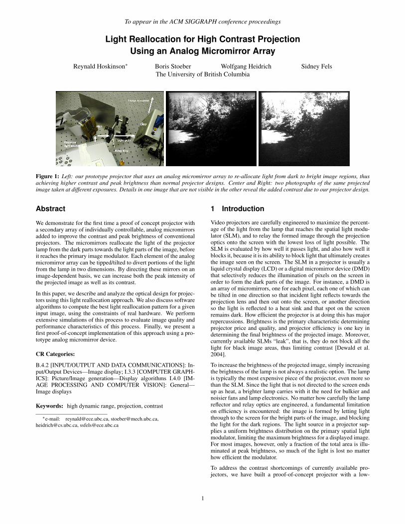
Figure 1: Left: our prototype projector that uses an analog micromirror array to re-allocate light from dark to bright image regions, thusachieving higher contrast and peak brightness than normal projector designs. Center and Right: two photographs of the same projectedimage taken at different exposures. Details in one image that are not visible in the other reveal the added contrast due to our projector design.
Abstract
We demonstrate for the first time a proof of concept projector witha secondary array of individually controllable, analog micromirrorsadded to improve the contrast and peak brightness of conventionalprojectors. The micromirrors reallocate the light of the projectorlamp from the dark parts towards the light parts of the image, beforeit reaches the primary image modulator. Each element of the analogmicromirror array can be tipped/tilted to divert portions of the lightfrom the lamp in two dimensions. By directing these mirrors on animage-dependent basis, we can increase both the peak intensity ofthe projected image as well as its contrast.
In this paper, we describe and analyze the optical design for projec-tors using this light reallocation approach. We also discuss softwarealgorithms to compute the best light reallocation pattern for a giveninput image, using the constraints of real hardware. We performextensive simulations of this process to evaluate image quality andperformance characteristics of this process. Finally, we present afirst proof-of-concept implementation of this approach using a pro-totype analog micromirror device.
CR Categories:
B.4.2 [INPUT/OUTPUT AND DATA COMMUNICATIONS]: In-put/Output Devices—Image display; I.3.3 [COMPUTER GRAPH-ICS]: Picture/Image generation—Display algorithms I.4.0 [IM-AGE PROCESSING AND COMPUTER VISION]: General—Image displays
Keywords: high dynamic range, projection, contrast
Video projectors are carefully engineered to maximize the percent-age of the light from the lamp that reaches the spatial light modu-lator (SLM), and to relay the formed image through the projectionoptics onto the screen with the lowest loss of light possible. TheSLM is evaluated by how well it passes light, and also how well itblocks it, because it is its ability to block light that ultimately createsthe image seen on the screen. The SLM in a projector is usually aliquid crystal display (LCD) or a digital micromirror device (DMD)that selectively reduces the illumination of pixels on the screen inorder to form the dark parts of the image. For instance, a DMD isan array of micromirrors, one for each pixel, each one of which canbe tilted in one direction so that incident light reflects towards theprojection lens and then out onto the screen, or another directionso the light is reflected to a heat sink and that spot on the screenremains dark. How efficient the projector is at doing this has majorrepercussions. Brightness is the primary characteristic determiningprojector price and quality, and projector efficiency is one key indetermining the final brightness of the projected image. Moreover,currently available SLMs “leak”, that is, they do not block all thelight for black image areas, thus limiting contrast [Dewald et al.2004].
To increase the brightness of the projected image, simply increasingthe brightness of the lamp is not always a realistic option. The lampis typically the most expensive piece of the projector, even more sothan the SLM. Since the light that is not directed to the screen endsup as heat, a brighter lamp carries with it the need for bulkier andnoisier fans and lamp electronics. No matter how carefully the lampreflector and relay optics are engineered, a fundamental limitationon efficiency is encountered: the image is formed by letting lightthrough to the screen for the bright parts of the image, and blockingthe light for the dark regions. The light source in a projector sup-plies a uniform brightness distribution on the primary spatial lightmodulator, limiting the maximum brightness for a displayed image.For most images, however, only a fraction of the total area is illu-minated at peak brightness, so much of the light is lost no matterhow efficient the modulator.
To address the contrast shortcomings of currently available pro-jectors, we have built a proof-of-concept projector with a low-
1
To appear in the ACM SIGGRAPH conference proceedings
resolution secondary mirror array that in effect turns the single lampinside a projector into a multitude of light sources that can each bemoved to where they are needed in the image. The secondary mirrordevice is capable of directing the uniform light from the projectorlamp incident on its surface to different areas on the light modu-lator, in effect projecting a low-resolution version of the originalimage onto the light modulator.
Adding this analog mirror device improves the dynamic range intwo ways: by directing the light to the bright parts of the image, theachievable peak brightness will be increased. Simultaneously, theamount of light that needs to be blocked in the dark regions of theimage will be reduced, thus decreasing the brightness of the blacklevel. This light redirection is realized with a low-resolution analogmicromirror array (AMA), fabricated using microelectromechani-cal system (MEMS) technology. The tip and tilt angle (two degreesof freedom) of the micromirrors in the array can be set continuouslyin order to direct light to an arbitrary location on the light modula-tor.
A projector using our design would be particularly suited to dis-playing high-dynamic range (HDR) images in an efficient man-ner. The AMA device closely parallels the use of a second,low-resolution spatial light modulator in HDR displays [Seet-zen et al. 2004]. Unlike earlier approaches for HDR projection(e.g. [Damberg et al. 2007; Pavlovych and Stuerzlinger 2005]), ourdesign reallocates rather than absorbs unwanted light. We are there-fore able to improve energy efficiency and reduce heat generationin much the same way as Seetzen et al.’s [2004] LED display designimproves efficiency over their initial double-absorption design.
However, there are also significant differences between our lightreallocation approach and the original dual-modulation HDR dis-plays. The most important difference is that the total amount oflight can be varied in Seetzen et al.’s work, while it is fixed in ourcase. Furthermore, the physical constraints of AMA devices resultin a limited maximum spatial displacement of light, which imposesadditional constraints on the light allocation. These differencesmandate new algorithms for light allocation, which we present inthis paper, along with the physical and optical design principles oflight reallocation projectors.
2 Related work
The concept of using a secondary mirror array was originally sug-gested in [Hoskinson and Stoeber 2008], but no proof-of-conceptwas developed, and there was no detailed optical analysis. Thiswork offers the first physical evidence of such an arrangement, andpresents a more efficient allocation algorithm for making use of thelight from the secondary mirror array.
The AMA acts as a second, low-resolution modulator, similar to thesystem described by Seetzen et al. [2004], where a low-resolutionindividually-controllable array of LEDs behind a high-resolutionLCD screen functions as a second modulator. The light distribu-tion of the low-resolution modulator is then corrected by the high-resolution modulator to achieve the desired image. In the workby Seetzen et al., the LEDs are in fixed locations, irrespective ofwhere the bright parts of the image are. In our approach, the back-light is instead composed of an array of spots of constant intensity,and each spot can be moved across the image plane. This meansthat light can be targeted to exactly where it is needed, for exampleboosting the peak brightness by directing multiple light spots intothe same spatial location.
The concept of using two light modulators in series put forwardby Seetzen et al. [2004] has primarily been applied to flat-paneldisplays, but has also been applied to several projector designs.
Conventional projectors use high-intensity discharge (HID) lamps,which are not suitable for placement in a tightly-packed array, andtypically operate efficiently only at one output intensity, so HIDlamps are not themselves suitable as modulators. Instead, some ap-proaches (e.g. [Pavlovych and Stuerzlinger 2005; Damberg et al.2007; Kusakabe et al. 2009]) improve projector contrast by addinga second LCD modulator into the light path, which significantlyreduces the overall black level of the system, but at the cost of asignificant reduction in overall brightness, as black and white LCDpanels typically transmit only 30-35% of unpolarized incident light.Matching polarization between the two LCD modulators so thatonly one polarization step is required only reduces the amount ofloss, it does not eliminate it.
A more fundamental problem is that additional absorption onlyadds extra bits of information at the dark end of the intensity range.This additional dynamic range is in practice only useful in darkrooms, since ambient illumination otherwise dominates that inten-sity range. Although we are not aware of any systems that employtwo DMDs in series, they would also improve solely in the darkintensities. Increasing useful dynamic range with these projectordesigns therefore requires brighter HID lights at significantly in-creased expense, power consumption, and heat production. Ourdesign, on the other hand, can increase peak intensity without achange in light source.
Both Bimber [2008] and Seetzen [2009] have suggested other ap-proaches to HDR projection that involve superimposing a projectedimage onto a paper print or a reflective display, such as e-ink. Theadvantage of this approach is that the change in reflectance affectsboth the light arriving from the projector, as well as the reflectedambient illumination, which makes this approach useful even in il-luminated rooms. However, Bimber’s approach is designed onlyfor static images such as X-rays. While Seetzen’s approach takesadvantage of interactive reflective displays such as e-ink to displaydynamic images, current e-ink displays are still too slow for prac-tical implementations of this concept, and screens of suitable sizewould likely be prohibitively expensive. Seetzen’s also proposesthe use of an array of hundreds or thousands of very small projec-tors with individual modulated light sources such as LEDs. Thisproposal has not yet been implemented in full scale, but one wouldexpect the calibration and alignment issues to be severe.
Some recent commercial projectors include a dynamic iris, aphysical aperture near the lamp that can change size with eachvideo frame, thus limiting the total illumination that reaches thescreen [Iisaka et al. 2003; Toyooka et al. 2005]. While this methodcan decrease the black level of certain images, this is only a globaladjustment that does not allow for contrast improvements within asingle image. In addition, our approach could easily be combinedwith a dynamic iris to produce even higher temporal dynamic range.
Lasers have also been used as a light source for projectors, in thefollowing three forms:
1. As a raster scanner, with a laser for each primary color, com-bined to one spot showing one pixel at a time. The spot movesover the image quickly enough so that each image is inte-grated by a human observer. The laser intensity is modulatedat video rate.
2. Linear arrays such as the grating light valve [1997], whichproduce the image through diffractive elements, one line ata time. A scanning mirror moves the single line through theimage over time.
3. As a conventional light source, with a DMD or other lightvalve technology.
2
To appear in the ACM SIGGRAPH conference proceedings
The primary reason the lasers have so far been kept out of com-modity displays is cost per lumen: laser sources bright enough formost forms of commodity projectors continue to be commerciallycost-prohibitive.
Conceivably, the time that a scanning laser spends at each pixelcould be varied to achieve a similar result as in this paper. Theproblem is that all raster-scanning laser projectors we are aware ofuse single or dual scanning mirrors tilting at resonance. This is me-chanically very advantageous, but also prevents varying laser/pixelexposure time. Doing so would involve a complete redesign of allmechanics. Laser projectors using linear arrays make use of diffrac-tion, and thus would be unsuitable for this sort of change. Usinglasers as conventional light sources, on the other hand, would becompatible with our system.
3 Optical system design
3.1 Spot position, size on spatial light valve
Our prototype is limited by the hardware available to us on an aca-demic budget, including analog micromirrors with less-than-idealfunctionality which constrain our results to a basic proof of con-cept. We therefore devote a considerable portion of this work totheoretically quantifying the limits and opportunities of the AMAapproach.
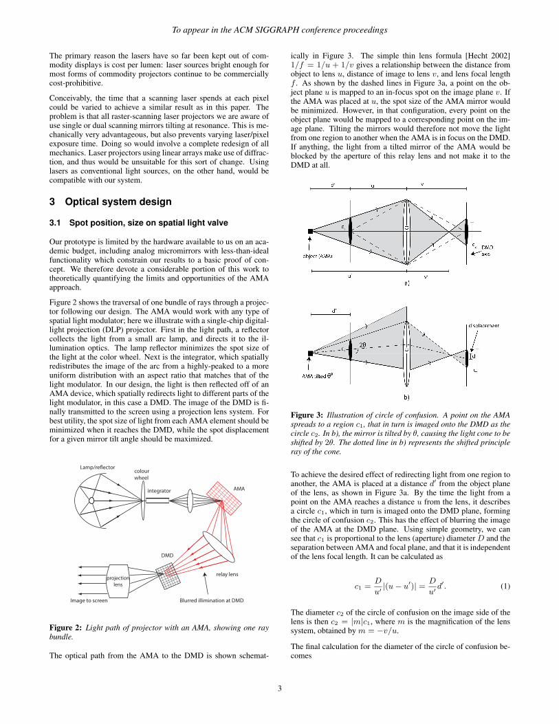
Figure 2 shows the traversal of one bundle of rays through a projec-tor following our design. The AMA would work with any type ofspatial light modulator; here we illustrate with a single-chip digital-light projection (DLP) projector. First in the light path, a reflectorcollects the light from a small arc lamp, and directs it to the il-lumination optics. The lamp reflector minimizes the spot size ofthe light at the color wheel. Next is the integrator, which spatiallyredistributes the image of the arc from a highly-peaked to a moreuniform distribution with an aspect ratio that matches that of thelight modulator. In our design, the light is then reflected off of anAMA device, which spatially redirects light to different parts of thelight modulator, in this case a DMD. The image of the DMD is fi-nally transmitted to the screen using a projection lens system. Forbest utility, the spot size of light from each AMA element should beminimized when it reaches the DMD, while the spot displacementfor a given mirror tilt angle should be maximized.
Lamp/re!ector colourwheel
integrator
fold mirror
relay lens
DMD
projectionlens
Lamp/re!ector colourwheel
integrator
relay lens
DMD
projectionlens
AMA
Image to screen Blurred illimination at DMD
Figure 2: Light path of projector with an AMA, showing one raybundle.
The optical path from the AMA to the DMD is shown schemat-
ically in Figure 3. The simple thin lens formula [Hecht 2002]1/f = 1/u + 1/v gives a relationship between the distance fromobject to lens u, distance of image to lens v, and lens focal lengthf . As shown by the dashed lines in Figure 3a, a point on the ob-ject plane u is mapped to an in-focus spot on the image plane v. Ifthe AMA was placed at u, the spot size of the AMA mirror wouldbe minimized. However, in that configuration, every point on theobject plane would be mapped to a corresponding point on the im-age plane. Tilting the mirrors would therefore not move the lightfrom one region to another when the AMA is in focus on the DMD.If anything, the light from a tilted mirror of the AMA would beblocked by the aperture of this relay lens and not make it to theDMD at all.
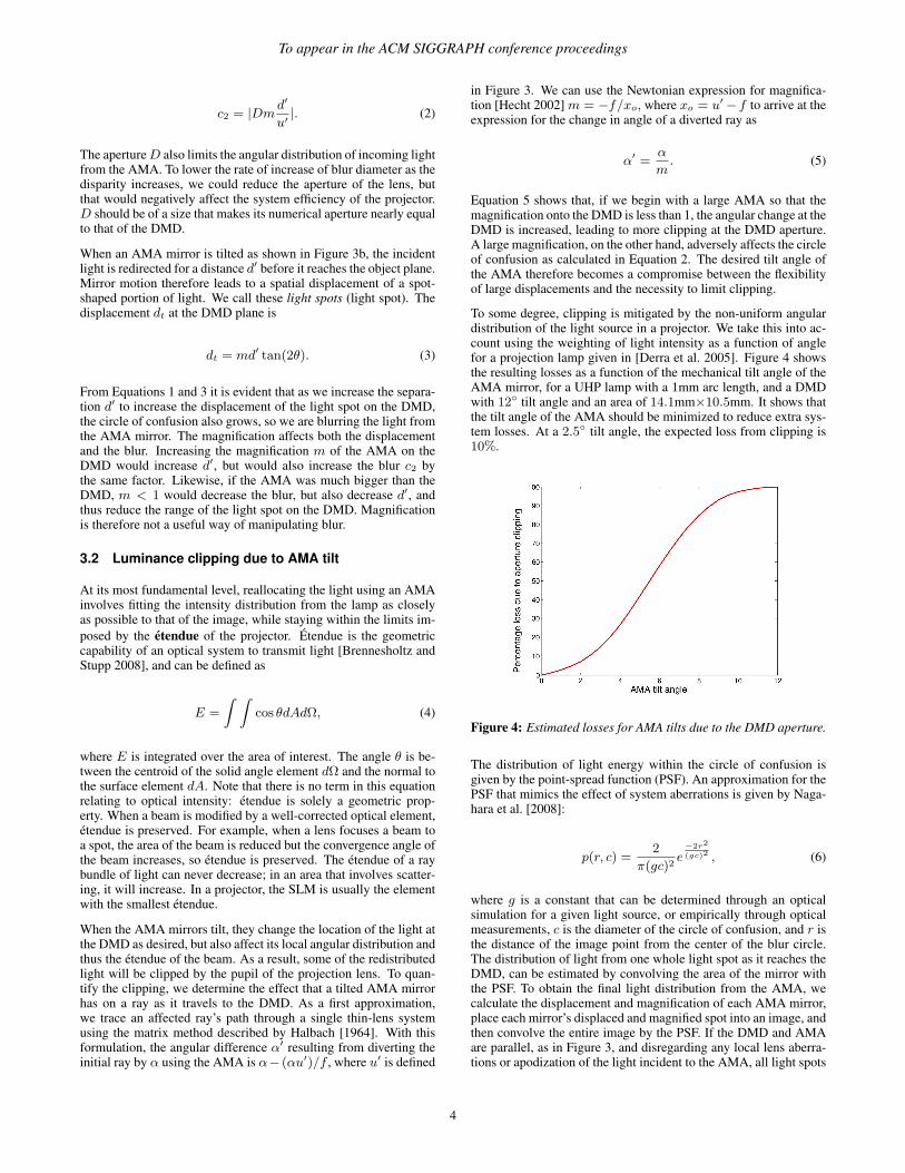
Figure 3: Illustration of circle of confusion. A point on the AMAspreads to a region c1, that in turn is imaged onto the DMD as thecircle c2. In b), the mirror is tilted by θ, causing the light cone to beshifted by 2θ. The dotted line in b) represents the shifted principleray of the cone.
To achieve the desired effect of redirecting light from one region toanother, the AMA is placed at a distance d′ from the object planeof the lens, as shown in Figure 3a. By the time the light from apoint on the AMA reaches a distance u from the lens, it describesa circle c1, which in turn is imaged onto the DMD plane, formingthe circle of confusion c2. This has the effect of blurring the imageof the AMA at the DMD plane. Using simple geometry, we cansee that c1 is proportional to the lens (aperture) diameter D and theseparation between AMA and focal plane, and that it is independentof the lens focal length. It can be calculated as
c1 =D
u′ |(u− u′)| = D
u′ d′. (1)
The diameter c2 of the circle of confusion on the image side of thelens is then c2 = |m|c1, where m is the magnification of the lenssystem, obtained by m = −v/u.
The final calculation for the diameter of the circle of confusion be-comes
3
To appear in the ACM SIGGRAPH conference proceedings
c2 = |Dmd′
u′ |. (2)
The aperture D also limits the angular distribution of incoming lightfrom the AMA. To lower the rate of increase of blur diameter as thedisparity increases, we could reduce the aperture of the lens, butthat would negatively affect the system efficiency of the projector.D should be of a size that makes its numerical aperture nearly equalto that of the DMD.
When an AMA mirror is tilted as shown in Figure 3b, the incidentlight is redirected for a distance d′ before it reaches the object plane.Mirror motion therefore leads to a spatial displacement of a spot-shaped portion of light. We call these light spots (light spot). Thedisplacement dt at the DMD plane is
dt = md′ tan(2θ). (3)
From Equations 1 and 3 it is evident that as we increase the separa-tion d′ to increase the displacement of the light spot on the DMD,the circle of confusion also grows, so we are blurring the light fromthe AMA mirror. The magnification affects both the displacementand the blur. Increasing the magnification m of the AMA on theDMD would increase d′, but would also increase the blur c2 bythe same factor. Likewise, if the AMA was much bigger than theDMD, m < 1 would decrease the blur, but also decrease d′, andthus reduce the range of the light spot on the DMD. Magnificationis therefore not a useful way of manipulating blur.
3.2 Luminance clipping due to AMA tilt
At its most fundamental level, reallocating the light using an AMAinvolves fitting the intensity distribution from the lamp as closelyas possible to that of the image, while staying within the limits im-posed by the etendue of the projector. Etendue is the geometriccapability of an optical system to transmit light [Brennesholtz andStupp 2008], and can be defined as
E =
Z Zcos θdAdΩ, (4)
where E is integrated over the area of interest. The angle θ is be-tween the centroid of the solid angle element dΩ and the normal tothe surface element dA. Note that there is no term in this equationrelating to optical intensity: etendue is solely a geometric prop-erty. When a beam is modified by a well-corrected optical element,etendue is preserved. For example, when a lens focuses a beam toa spot, the area of the beam is reduced but the convergence angle ofthe beam increases, so etendue is preserved. The etendue of a raybundle of light can never decrease; in an area that involves scatter-ing, it will increase. In a projector, the SLM is usually the elementwith the smallest etendue.
When the AMA mirrors tilt, they change the location of the light atthe DMD as desired, but also affect its local angular distribution andthus the etendue of the beam. As a result, some of the redistributedlight will be clipped by the pupil of the projection lens. To quan-tify the clipping, we determine the effect that a tilted AMA mirrorhas on a ray as it travels to the DMD. As a first approximation,we trace an affected ray’s path through a single thin-lens systemusing the matrix method described by Halbach [1964]. With thisformulation, the angular difference α′ resulting from diverting theinitial ray by α using the AMA is α− (αu′)/f , where u′ is defined
in Figure 3. We can use the Newtonian expression for magnifica-tion [Hecht 2002] m = −f/xo, where xo = u′− f to arrive at theexpression for the change in angle of a diverted ray as
α′ =α
m. (5)
Equation 5 shows that, if we begin with a large AMA so that themagnification onto the DMD is less than 1, the angular change at theDMD is increased, leading to more clipping at the DMD aperture.A large magnification, on the other hand, adversely affects the circleof confusion as calculated in Equation 2. The desired tilt angle ofthe AMA therefore becomes a compromise between the flexibilityof large displacements and the necessity to limit clipping.
To some degree, clipping is mitigated by the non-uniform angulardistribution of the light source in a projector. We take this into ac-count using the weighting of light intensity as a function of anglefor a projection lamp given in [Derra et al. 2005]. Figure 4 showsthe resulting losses as a function of the mechanical tilt angle of theAMA mirror, for a UHP lamp with a 1mm arc length, and a DMDwith 12 tilt angle and an area of 14.1mm×10.5mm. It shows thatthe tilt angle of the AMA should be minimized to reduce extra sys-tem losses. At a 2.5 tilt angle, the expected loss from clipping is10%.
Figure 4: Estimated losses for AMA tilts due to the DMD aperture.
The distribution of light energy within the circle of confusion isgiven by the point-spread function (PSF). An approximation for thePSF that mimics the effect of system aberrations is given by Naga-hara et al. [2008]:
p(r, c) =2
π(gc)2e−2r2
(gc)2 , (6)
where g is a constant that can be determined through an opticalsimulation for a given light source, or empirically through opticalmeasurements, c is the diameter of the circle of confusion, and r isthe distance of the image point from the center of the blur circle.The distribution of light from one whole light spot as it reaches theDMD, can be estimated by convolving the area of the mirror withthe PSF. To obtain the final light distribution from the AMA, wecalculate the displacement and magnification of each AMA mirror,place each mirror’s displaced and magnified spot into an image, andthen convolve the entire image by the PSF. If the DMD and AMAare parallel, as in Figure 3, and disregarding any local lens aberra-tions or apodization of the light incident to the AMA, all light spots
4
To appear in the ACM SIGGRAPH conference proceedings
will have equal shape. If the two chips are not parallel, the distribu-tion of each light spot will need to be calculated separately, becauseeach will have a different PSF, due to the differing distances be-tween points on the AMA and points on the DMD.
4 Light allocation
Finding the optimal light distribution for the AMA corresponds tochoosing the locations for each of the n light spots from the arrayof n analog micromirrors. It is assumed that there is adequate gran-ularity in the mirror control to position a light spot at any pixel inthe image. To guide the allocation algorithm, we define an imageimprovement factor as the ability to boost the entire range of pixelbrightness values, both dark and bright. This improvement is de-fined as a ratio, compared to a conventional projector design usingthe same DMD and light source without an AMA device. Since theAMA is only re-allocating rather than generating new light, this im-provement factor is image-dependent. A uniform white image willsee no improvement in peak brightness, while images with a fewbright features on a dark background can be improved the most.
4.1 Gaussian pyramids
In [Hoskinson and Stoeber 2008], an approach using a Gaussianpyramid is described. Both the image and the light spot are low-pass filtered a number of times, each of which becomes a level ofthe pyramid. Starting at the coarsest level of the pyramid, the po-sition of each of the light spots is iteratively adjusted towards thehigher intensity regions, one at a time. This process is repeateddown the pyramid to the finest level of detail.
4.2 Median cut approach
An alternative to allocating light spot via the process of analyzing aGaussian pyramid is to divide the original image into equal energyzones, and allocate one light spot for each zone. The median cut al-gorithm described by Debevec [2005], a variation from the originaldescribed in Heckbert [1982], is an efficient method of subdividingan image into zones of approximately equal energy. Figure 5 showsan image cut into 28 regions. A light spot is placed with its centerat the centroid of each region, here marked with squares. Using thisapproach, the image can be divided quickly into as many regions asthere are light spots. With the Gaussian pyramid scheme, there arestill many more pixels than there are spots at the coarsest level ofthe pyramid, so the initial allocation is much less representative ofthe actual intensity distribution of the pixels.
A light spot can have a limited range of movement from its originalposition due to the limited tilt angle of the micromirrors, which isnot taken into account in the median cut algorithm. In the Euclideanbipartite minimum matching problem [Agarwal and Varadarajan2004], we are given an equal number of points from two sets, andwould like to match a point from one set with a distinct point fromthe other set, so that the sum of distances between the paired pointsis minimized. We can use an algorithm that solves this problemto match each centroid from the median cut step to a location of alight spot in its rest (non-tilted) state, and thus minimize the sumtotal distance between the pairs in the two groups. This will min-imize the sum total angle that the mirrors must tilt to achieve thepoints specified in the median cut solution set.
The Euclidean bipartite matching problem can be solved in polyno-mial time using Kuhn’s Hungarian approach [1955]. The Hungar-ian approach does not support constraints such as maximum valuesfor pairs, meaning that there might be some pairs that exceed therange of motion of an light spot for a given maximum mirror tilt
Figure 5: An image divided into 28 regions of roughly equal en-ergy using the median cut algorithm. A light spot is placed at thecentroid of each region (represented as dots).
angle. If any of the distances between the non-tilted light spot andthe centroid are larger than the range, they are placed at the furthestpoint along the line that connects the two points. Figure 6 shows theresults of using the median cut algorithm on the image in Figure 5.
In the end, the placement of each light spot provides a heteroge-neous illumination Ip for the second modulator, in this case theDMD. We must correct for this variable illumination in the im-age that we send to the high-resolution modulator. The final re-sult for the projected image will be a per-pixel optical multipli-cation of the two modulators: kIm(i, j) = IDMD(i, j)Ip(i, j),where k represents the improvement in brightness. IDMD is thussimply equal to kIm(i, j)/Ip(i, j), quantized to the 256 possiblegreyscale states of the DMD. The largest possible improvementfactor k will depend on the luminance distribution of the image.If every single displayed pixel is required to have sufficient lumi-nance, k = arg min(Ip/Im). At a higher k, some pixels cannot bereproduced at the luminance specified by kIm.
4.3 Iterative adjustment
The solution obtained by using the median cut algorithm can be op-timized by performing an iterative adjustment step. After the initialmedian cut solution is determined, the pixel with the minimum im-provement is found, the closest light spot moved towards it, and theimage improvement is evaluated at points along the path. The lightspot is moved to the point along the path that scores highest. Thisprocess is repeated for each of the light spots until no movement to-wards the minimum improved pixel by any of the light spots resultsin a positive change.
5 Simulation results and analysis
The final achievable improvement k can be used to evaluate thechoices for light spot size, range and number given as initial condi-tions to the simulation. The key variables are:
• Range: The distance, in pixels, along which a light source canmove. This depends on the optical system and the maximumtilt angle achievable by the AMA micromirrors.
• Blur: The higher the disparity, the larger the blur, and alsothe larger the range of the mobile light source.
5
To appear in the ACM SIGGRAPH conference proceedings
Figure 6: Diagram of placements of light spot for the image in Fig-ure 5 using the median cut algorithm, with a mirror range of 100pixels. The starting (small red dots) and ending (arrowheads) loca-tions of each light spot are shown, as well as where they would havegone had they had unlimited range (green dotted line). The borderof the SLM is shown as a rectangle. Some of the light spot startfrom beyond the border because of the required overfill to achievea uniform illumination of the SLM.
• Number of mirrors: The number of mirrors within theAMA. With more mirrors, more details in the image can becovered with separate emphasis. It is therefore estimated thata larger number of mirrors will provide more improvement.However, more mirrors also imply a greater physical cost andcomplexity of the mirror array and its drivers.
With measurements or assumptions of the blur and achievable tiltangle of an AMA mirror, the allocation system can be used to sim-ulate the projector’s effectiveness. Test images were chosen to givedifferent views into the behavior of the system. Figure 7a has a darksection at the bottom and a section of high intensity in the sky andon the peak of the mountain. The second test image, in Figure 7b,also has a bright sky region, but most of the darker regions are inter-spersed with brighter regions, which will make it more difficult tomove light from one region to another without affecting fine detail.The third (Figure 7c) is an artificial test pattern that is often used toevaluate the contrast of video projectors.
Figure 7: Test images: a) Mt. Robson, b) Rocky beach, c) ANSICheckerboard.
Each test image and algorithm was simulated for a range of blurlevels, number of mirrors, and light spot range. The median cut al-gorithm detailed above was compared against the Gaussian pyramidalgorithm from [Hoskinson and Stoeber 2008]. For each condition,the improvement factor k was recorded. This gave a large matrix ofdata that was used to qualitatively analyze the effect of each condi-
tion. A selection of results for 30mm disparity and 400 pixel rangeis given in Table 1.
Table 1: Improvement factors for different configurations and testimages (simulation results). Results are listed for the cases where100% and 99.5% of pixels are sufficiently illuminated.
For all tested algorithms, limiting the mirror movement to below200 pixels severely impacts the possible improvement factor, irre-spective of blur level or mirror numbers. Since range depends ondisparity and mirror tilt angle, smaller ranges are easier to engi-neer and result in less clipping. The more separately-controllablemirrors in the array, the better the opportunity for improvement,because they offer more degrees of freedom to tailor the light dis-tribution on the DMD to the desired image. The selection of resultsin Table 1 (values for 100%) shows that significant improvementsare possible for a range of physically feasible parameters.
5.1 Allowing under-illuminated pixels
The results show that the choice of algorithm has a large impacton the improvement factor. This could be due to the algorithms’sensitivity to outliers. The improvement factor is set by the pixelwith the minimum ratio of light given to light required (Ip/Im). Allit takes is one outlying pixel to bring down the improvement factor.If a particular pixel is an outlier, it may be that the rest of the imagecould have been shown at a much higher brightness if that pixelwere ignored, with little perceivable loss. We tested how muchbrighter the image could get if we allowed a certain percentage ofpixels to be under-illuminated compared to the rest of the image.
0 10 20 30 40 50 60 70 80 90 1001.8
2
2.2
2.4
2.6
2.8
3
Number of under−illuminated pixels
Impr
ovem
ent f
acto
r
PyramidMed cutMed cut with adjustment
Figure 8: Improvement factor increase for the Mt. Robson imagein Figure 7 when allowing some of the 600 × 800 = 480000 totalpixels to be under-illuminated.
6
To appear in the ACM SIGGRAPH conference proceedings
Figure 8 shows the performance of the three algorithms tested forthe Mt. Robson image, with a blur from 60 mm disparity, an AMAwith 7 × 4 mirrors, and a range of 300 pixels. For the case inwhich all pixels receive enough light, the pyramid (GP) representa-tion scores highest with a 2.44 improvement factor, while mediancut with iterative adjustment (MCIA) scores 2.32, and just usingMC placement scores 1.9.
But at just 20 under-illuminated pixels (which, for an 800x600 im-age, is 0.004%), GP is overtaken by both median cut versions. GPscores 2.71, while MC alone scores 2.8, and MCIA scores 3.07.That is a 26% increase in brightness over the highest score obtainedfor perfect reconstruction. The increase raises to 36% if 50 pixelsare allowed to be under-illuminated. The other two images testedare consistent with this trend. Figure 8 shows that the median cutalgorithms are sensitive to outliers, and much more overall bright-ness increases can be achieved if the requirements are loosened.
Even if allowing under-illuminated pixels is not desirable undernormal conditions, these tests show that there is a lot of flexibil-ity to tailor the performance to different conditions. For instance,when displaying a video sequence on an AMA projector, the poten-tial improvement factor will vary over time as the image changes,depending on the sum total intensity in the image and its distribu-tion. If it changes too quickly or the magnitude of the change istoo abrupt, the viewer will notice the artificial change in relativebrightnesses of the different features in the image. Figure 8 showsthat fixing the improvement factor for this video sequence does notnecessarily mean fixing it at the minimum value out of all images inthe sequence. By allowing some pixels to be under-illuminated, theimprovement factor can be set at a higher level that matches what isachievable for an average image in the sequence, not the minimum.
5.2 Estimated system performance
Adding the AMA will incur some light losses that partially offsetthe gains described above. We can estimate the efficiency of a pro-duction version of the AMA at reflecting incident light by compar-ing it to the DMD. The DMD reflects eD = 68% of incident light[Texas Instruments 2005]. The fill-factor of the AMA could be in-creased, because the AMA requires fewer mirrors than the DMD,and thus could have less total space between them. Also, the AMAwill replace an existing fold mirror in the projector, which cancelsout reflectance losses. Assuming an average tilt angle of 2.5, theexpected loss from clipping is 10% from Figure 4. Given these as-sumptions, we estimate the efficiency of the AMA as eA = 74%.Although this represents a significant loss of light, we still antici-pate that the AMA-enabled projector would have a net gain of peakbrightness. With 40mm blur disparity and 300 pixel range, the aver-age improvement factor was 1.61, giving a net improvement factorof 1.20 after taking into account these losses. If we allow some pix-els to remain under-illuminated, the case becomes even stronger.With 200 under-illuminated pixels, the average score for the me-dian cut algorithm with iterative adjustment was 3.07. After takinginto account losses, this still leaves a factor of 2.25 improvement.
5.3 Image fidelity
The addition of an AMA potentially introduces image distortionsthat can be attributed to the following main sources:
Quantization. There are only 256 greyscale values in a DLP.There will thus be errors due to quantization as the DMDcannot compensate accurately enough for the continuous, non-homogeneous illumination from the AMA.
Over-illumination. Over-illumination occurs because of lightleakage due to the limited contrast of light modulators, and becomesnon-uniform as the backlight is modulated. To estimate the amountof leakage in a projector for a given amount of luminance, the na-tive contrast ratio of the device and peak brightness is measured. Ifthe peak brightness of the projector is x, and contrast ratio is 1 : y,then the estimated brightness of a pixel set to its darkest level in theDMD is x/y. If the pixel is set to a brightness of z, the estimatedresult is z + x/y. While this is not a perfect estimate due to thevariability of lens scattering and possible non-linear effects, it pro-vides a base level to compare the difference in an AMA-projectorto a conventional projector.
Under-illumination. As mentioned above, it is possible to sacri-fice some accuracy for overall brightness by allowing some pixelsto be under-illuminated compared to the rest of the image. We canensure this does not happen by specifying to the allocation algo-rithm that all pixels must have sufficient light, but how many under-illuminated pixels could be present without adversely affecting theviewing experience, and under what conditions?
To quantify the effect of these inaccuracies, the simulated opticalcombination of the AMA image on the DMD (IP ) and the DMDimage are compared against the original image using an automatedvisual difference predictor designed for high dynamic range imagesas well as conventional images [Mantiuk et al. 2005]. The VDP al-gorithm provides a metric to distinguish the subset of differencesbetween two images that a standard human observer would be ableto detect. Our objective is to establish visual equivalence betweenimages made with an AMA-equipped projector, compared to a reg-ular projector that has the same peak brightness as the improvedimage.
We tested the configuration of a 7× 4 array of mirrors with a rangeof 300 pixels, and a PSF with a full-width at half-maximum of297 pixels. With DMD pixels being approximately 14µm square,the micromirror mechanical tilt angle needed to traverse 300 pix-els is ±2, which is well within the range of published micromir-rors [Hoskinson et al. 2010; Tsai et al. 2008]. Ip is a continuously-varying analog distribution on the DMD, and thus simulating quan-tization can be done by only quantizing IDMD. The limited contrastof the projector is simulated by adding a portion of Ip to the result-ing image.
Imc = IDMD + Ip/c, (7)
where c refers to the contrast ratio of the DMD. For instance, if wetake a conservative value of 1 : 400 contrast ratio for the DMD, cis 400. Imc is compared against kIm, where k is the improvementfactor.
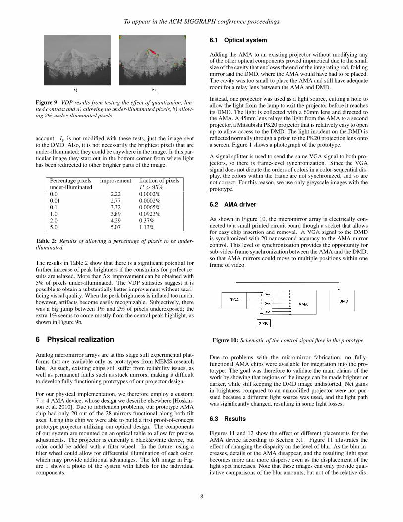
With quantization taken into account, the VDP algorithm predictedthat there was a probability of detection P > 95% for 0.0002% ofthe pixels, as shown in Figure 9a. For an 800 × 600 image, thisworks out to 96 pixels. The affected pixels are hardly visible at thebottom right-hand corner of the image.
Given that quantization and contrast issues did not significantly af-fect the image at this peak brightness, there is potential to signifi-cantly increase the overall brightness of the image if the constraintsfor perfect reproduction are relaxed. Table 2 shows the results ofincreasing the improvement factor to various levels, depending onthe percentage of pixels that become under-illuminated. For 0.01%pixel error, which would allow for an improvement factor of 2.77,VDP calculated that only 0.0002% of pixels might be noticed. Thatis the same as the VDP result when all pixels are sufficiently illu-minated, and only contrast and quantization artifacts are taken into
7
To appear in the ACM SIGGRAPH conference proceedings
Figure 9: VDP results from testing the effect of quantization, lim-ited contrast and a) allowing no under-illuminated pixels, b) allow-ing 2% under-illuminated pixels
account. Ip is not modified with these tests, just the image sentto the DMD. Also, it is not necessarily the brightest pixels that areunder-illuminated; they could be anywhere in the image. In this par-ticular image they start out in the bottom corner from where lighthas been redirected to other brighter parts of the image.
Table 2: Results of allowing a percentage of pixels to be under-illuminated.
The results in Table 2 show that there is a significant potential forfurther increase of peak brightness if the constraints for perfect re-sults are relaxed. More than 5× improvement can be obtained with5% of pixels under-illuminated. The VDP statistics suggest it ispossible to obtain a substantially better improvement without sacri-ficing visual quality. When the peak brightness is inflated too much,however, artifacts become easily recognizable. Subjectively, therewas a big jump between 1% and 2% of pixels underexposed; theextra 1% seems to come mostly from the central peak highlight, asshown in Figure 9b.
6 Physical realization
Analog micromirror arrays are at this stage still experimental plat-forms that are available only as prototypes from MEMS researchlabs. As such, existing chips still suffer from reliability issues, aswell as permanent faults such as stuck mirrors, making it difficultto develop fully functioning prototypes of our projector design.
For our physical implementation, we therefore employ a custom,7× 4 AMA device, whose design we describe elsewhere [Hoskin-son et al. 2010]. Due to fabrication problems, our prototype AMAchip had only 20 out of the 28 mirrors functional along both tiltaxes. Using this chip we were able to build a first proof-of-conceptprototype projector utilizing our optical design. The componentsof our system are mounted on an optical table to allow for preciseadjustments. The projector is currently a black&white device, butcolor could be added with a filter wheel. In the future, using afilter wheel could allow for differential illumination of each color,which may provide additional advantages. The left image in Fig-ure 1 shows a photo of the system with labels for the individualcomponents.
6.1 Optical system
Adding the AMA to an existing projector without modifying anyof the other optical components proved impractical due to the smallsize of the cavity that encloses the end of the integrating rod, foldingmirror and the DMD, where the AMA would have had to be placed.The cavity was too small to place the AMA and still have adequateroom for a relay lens between the AMA and DMD.
Instead, one projector was used as a light source, cutting a hole toallow the light from the lamp to exit the projector before it reachesits DMD. The light is collected with a 60mm lens and directed tothe AMA. A 45mm lens relays the light from the AMA to a secondprojector, a Mitsubishi PK20 projector that is relatively easy to openup to allow access to the DMD. The light incident on the DMD isreflected normally through a prism to the PK20 projection lens ontoa screen. Figure 1 shows a photograph of the prototype.
A signal splitter is used to send the same VGA signal to both pro-jectors, so there is frame-level synchronization. Since the VGAsignal does not dictate the orders of colors in a color-sequential dis-play, the colors within the frame are not synchronized, and so arenot correct. For this reason, we use only greyscale images with theprototype.
6.2 AMA driver
As shown in Figure 10, the micromirror array is electrically con-nected to a small printed circuit board though a socket that allowsfor easy chip insertion and removal. A VGA signal to the DMDis synchronized with 20 nanosecond accuracy to the AMA mirrorcontrol. This level of synchronization provides the opportunity forsub-video-frame synchronization between the AMA and the DMD,so that AMA mirrors could move to multiple positions within oneframe of video.
Figure 10: Schematic of the control signal flow in the prototype.
Due to problems with the micromirror fabrication, no fully-functional AMA chips were available for integration into the pro-totype. The goal was therefore to validate the main claims of thework by showing that regions of the image can be made brighter ordarker, while still keeping the DMD image undistorted. Net gainsin brightness compared to an unmodified projector were not pur-sued because a different light source was used, and the light pathwas significantly changed, resulting in some light losses.
6.3 Results
Figures 11 and 12 show the effect of different placements for theAMA device according to Section 3.1. Figure 11 illustrates theeffect of changing the disparity on the level of blur. As the blur in-creases, details of the AMA disappear, and the resulting light spotbecomes more and more disperse even as the displacement of thelight spot increases. Note that these images can only provide qual-itative comparisons of the blur amounts, but not of the relative dis-
8
To appear in the ACM SIGGRAPH conference proceedings
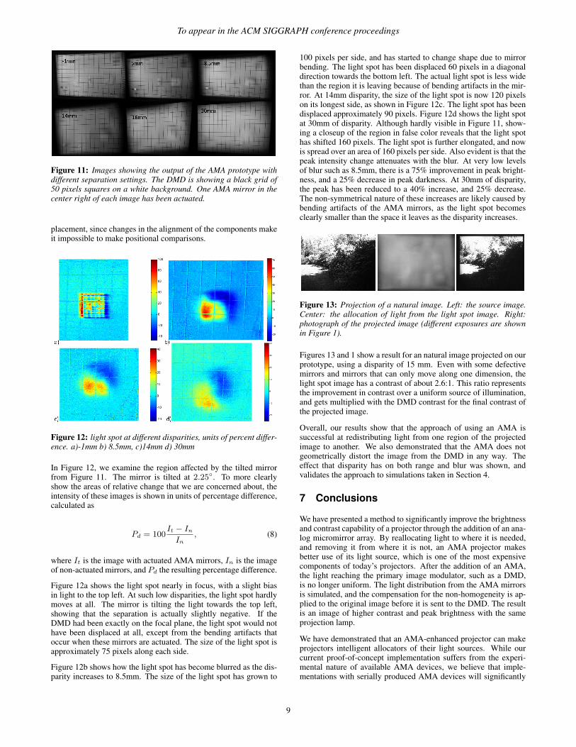
Figure 11: Images showing the output of the AMA prototype withdifferent separation settings. The DMD is showing a black grid of50 pixels squares on a white background. One AMA mirror in thecenter right of each image has been actuated.
placement, since changes in the alignment of the components makeit impossible to make positional comparisons.
Figure 12: light spot at different disparities, units of percent differ-ence. a)-1mm b) 8.5mm, c)14mm d) 30mm
In Figure 12, we examine the region affected by the tilted mirrorfrom Figure 11. The mirror is tilted at 2.25. To more clearlyshow the areas of relative change that we are concerned about, theintensity of these images is shown in units of percentage difference,calculated as
Pd = 100It − In
In, (8)
where It is the image with actuated AMA mirrors, In is the imageof non-actuated mirrors, and Pd the resulting percentage difference.
Figure 12a shows the light spot nearly in focus, with a slight biasin light to the top left. At such low disparities, the light spot hardlymoves at all. The mirror is tilting the light towards the top left,showing that the separation is actually slightly negative. If theDMD had been exactly on the focal plane, the light spot would nothave been displaced at all, except from the bending artifacts thatoccur when these mirrors are actuated. The size of the light spot isapproximately 75 pixels along each side.
Figure 12b shows how the light spot has become blurred as the dis-parity increases to 8.5mm. The size of the light spot has grown to
100 pixels per side, and has started to change shape due to mirrorbending. The light spot has been displaced 60 pixels in a diagonaldirection towards the bottom left. The actual light spot is less widethan the region it is leaving because of bending artifacts in the mir-ror. At 14mm disparity, the size of the light spot is now 120 pixelson its longest side, as shown in Figure 12c. The light spot has beendisplaced approximately 90 pixels. Figure 12d shows the light spotat 30mm of disparity. Although hardly visible in Figure 11, show-ing a closeup of the region in false color reveals that the light spothas shifted 160 pixels. The light spot is further elongated, and nowis spread over an area of 160 pixels per side. Also evident is that thepeak intensity change attenuates with the blur. At very low levelsof blur such as 8.5mm, there is a 75% improvement in peak bright-ness, and a 25% decrease in peak darkness. At 30mm of disparity,the peak has been reduced to a 40% increase, and 25% decrease.The non-symmetrical nature of these increases are likely caused bybending artifacts of the AMA mirrors, as the light spot becomesclearly smaller than the space it leaves as the disparity increases.
Figure 13: Projection of a natural image. Left: the source image.Center: the allocation of light from the light spot image. Right:photograph of the projected image (different exposures are shownin Figure 1).
Figures 13 and 1 show a result for an natural image projected on ourprototype, using a disparity of 15 mm. Even with some defectivemirrors and mirrors that can only move along one dimension, thelight spot image has a contrast of about 2.6:1. This ratio representsthe improvement in contrast over a uniform source of illumination,and gets multiplied with the DMD contrast for the final contrast ofthe projected image.
Overall, our results show that the approach of using an AMA issuccessful at redistributing light from one region of the projectedimage to another. We also demonstrated that the AMA does notgeometrically distort the image from the DMD in any way. Theeffect that disparity has on both range and blur was shown, andvalidates the approach to simulations taken in Section 4.
7 Conclusions
We have presented a method to significantly improve the brightnessand contrast capability of a projector through the addition of an ana-log micromirror array. By reallocating light to where it is needed,and removing it from where it is not, an AMA projector makesbetter use of its light source, which is one of the most expensivecomponents of today’s projectors. After the addition of an AMA,the light reaching the primary image modulator, such as a DMD,is no longer uniform. The light distribution from the AMA mirrorsis simulated, and the compensation for the non-homogeneity is ap-plied to the original image before it is sent to the DMD. The resultis an image of higher contrast and peak brightness with the sameprojection lamp.
We have demonstrated that an AMA-enhanced projector can makeprojectors intelligent allocators of their light sources. While ourcurrent proof-of-concept implementation suffers from the experi-mental nature of available AMA devices, we believe that imple-mentations with serially produced AMA devices will significantly
9
To appear in the ACM SIGGRAPH conference proceedings
improve contrast in future commercial projector systems, while al-lowing for less expensive lamps, lower heat production, and smallerprojector form factors.
Acknowledgments
We would like to acknowledge the fabrication provided by CMCMicrosystems (www.cmc.ca) that facilitated this research. Thiswork was in part supported by Dolby Labs, the Institute for Math-ematics of Information Technology and Complex Systems (MI-TACS), and the National Science and Engineering Research Coun-cil (NSERC).
References
AGARWAL, P., AND VARADARAJAN, K. 2004. A near-linearconstant-factor approximation for euclidean bipartite matching?In Proceedings of the twentieth annual symposium on Computa-tional geometry, ACM New York, NY, USA, 247–252.
BIMBER, O., AND IWAI, D. 2008. Superimposing dynamic range.ACM Trans. Graph. (Proc. Siggraph Asia) 27, 5, 1–8.
BLOOM, D., 1997. The grating light valve: revolutionizing displaytechnology.
BRENNESHOLTZ, M. S., AND STUPP, E. H. 2008. ProjectionDisplays, 2nd ed. Wiley.
DAMBERG, G., SEETZEN, H., WARD, G., HEIDRICH, W., ANDWHITEHEAD, L. 2007. High Dynamic Range Projection Sys-tems. Proceedings of the 2006 Society for Information DisplayAnnual Symposium.
DEBEVEC, P. 2005. A median cut algorithm for light probesampling. In SIGGRAPH ’05: ACM SIGGRAPH 2005 Posters,ACM, New York, NY, USA, 66.
DERRA, G., MOENCH, H., FISCHER, E., GIESE, H., HECHT-FISCHER, U., HEUSLER, G., KOERBER, A., NIEMANN, U.,NOERTEMANN, F., PEKARSKI, P., ET AL. 2005. UHP lampsystems for projection applications. JOURNAL OF PHYSICS-LONDON-D APPLIED PHYSICS 38, 17, 2995.
DEWALD, D., SEGLER, D., AND PENN, S. 2004. Advances incontrast enhancement for DLP projection displays. Journal ofthe Society for Information Display 11, 177–181.
HALBACH, K. 1964. Matrix representation of Gaussian optics.American Journal of Physics 32, 90.
HECHT, E. 2002. Optics, 4th ed. Addison Wesley, San Francisco,CA, USA.
HECKBERT, P. 1982. Color image quantization for frame bufferdisplay. ACM SIGGRAPH Computer Graphics 16, 3, 297–307.
HOSKINSON, R., AND STOEBER, B. 2008. High-dynamic rangeimage projection using an auxiliary mems mirror array. OpticsExpress 16, 7361–7368.
HOSKINSON, R., BUESCHER, D., HAMPL, S., HOLLE, M., ANDSTOEBER, B. 2010. Arrays of large-area, large-angle tip/tiltmicromirrors for use in a high-contrast projector. In submission.
IISAKA, H., TOYOOKA, T., YOSHIDA, S., AND NAGATA, M.2003. Novel Projection System Based on an Adaptive DynamicRange Control Concept. In Procoeedings Int Disp Workshops,vol. 10, 1553–1556.
KUHN, H. 1955. The Hungarian method for the assignment andtransportation problems. Naval Research Logistics Quarterly 2,83–97.
KUSAKABE, Y., KANAZAWA, M., NOJIRI, Y., FURUYA, M.,AND YOSHIMURA, M. 2009. A high-dynamic-range and high-resolution projector with dual modulation. In Proceedings ofSPIE, vol. 7241.
MANTIUK, R., DALY, S., MYSZKOWSKI, K., AND SEIDEL, H.-P.2005. Predicting visible differences in high dynamic range im-ages - model and its calibration. In Human Vision and ElectronicImaging X, IS&T/SPIE’s 17th Annual Symposium on ElectronicImaging (2005), B. E. Rogowitz, T. N. Pappas, and S. J. Daly,Eds., vol. 5666, 204–214.
NAGAHARA, H., KUTHIRUMMAL, S., ZHOU, C., AND NAYAR,S. 2008. Flexible Depth of Field Photography. In EuropeanConference on Computer Vision (ECCV).
PAVLOVYCH, A., AND STUERZLINGER, W. 2005. A High-Dynamic Range Projection System. Progress in biomedical op-tics and imaging 6, 39.
SEETZEN, H., HEIDRICH, W., STUERZLINGER, W., WARD,G., WHITEHEAD, L., TRENTACOSTE, M., GHOSH, A., ANDVOROZCOVS, A. 2004. High dynamic range display systems.ACM Transactions on Graphics (Siggraph 2004) 23, 3, 760–768.
SEETZEN, H. 2009. High Dynamic Range Display and ProjectionSystems. PhD thesis, University of British Columbia.
TOYOOKA, T., YOSHIDA, S., AND IISAKA, H. 2005. Illuminationcontrol system for adaptive dynamic range control. Journal ofthe Society for Information Display 13, 105.
TSAI, J., CHIOU, S., HSIEH, T., SUN, C., HAH, D., AND WU, M.2008. Two-axis MEMS scanners with radial vertical combdriveactuators—design, theoretical analysis, and fabrication. Journalof Optics A: Pure and Applied Optics 10, 044006.