43

8/8/2019 Light Trench Mortar Drill Regulations
http://slidepdf.com/reader/full/light-trench-mortar-drill-regulations 1/40

8/8/2019 Light Trench Mortar Drill Regulations
http://slidepdf.com/reader/full/light-trench-mortar-drill-regulations 2/40
-'0".'"".
LIGHT TRENCI-I MORTAR
DRILL REGULATIONS
(I... T. M. 1>. R.)
•

8/8/2019 Light Trench Mortar Drill Regulations
http://slidepdf.com/reader/full/light-trench-mortar-drill-regulations 3/40
•
WAR DEPARTMENTDOCUMENT No. 811
A. E. Ii'. No. 550
Office or the Adjutant General

8/8/2019 Light Trench Mortar Drill Regulations
http://slidepdf.com/reader/full/light-trench-mortar-drill-regulations 4/40
WAR DEPARTME~T
WASHINGTON, July I, 1918
Tho followillg pamphlet, entitled "Light Trench Mortar
Drill neguilltiom~," is published for the information anr.l
guida,nco of all concern('d.
(OG2.1 A.G.O.)
Dy ORDER 01~ TilE Si~CRETARY OF WAR:
}>EYTO~ C. MARCH,
General, ChieJ oj Staff
OFFICIAL:
11. I). :McCAIN,The Adjutant General
MORRIS swmTECHNICAL UBRAR\I: •USAFAS StJO\"1 HALL
~~T SILL, OKL/\. 7350~
~

8/8/2019 Light Trench Mortar Drill Regulations
http://slidepdf.com/reader/full/light-trench-mortar-drill-regulations 5/40
21222222
23
262t1211
27
2R2B
2{)
30
3030313132 ;
32
3335
31137
3~
311
40
40
40
41
()J
TABLE OF CONTENTS
ragA7
Light trench mortar drill regulation8 (L. T. M. D. R.) •••••.•••.•. , •• .• 7
Chaptl'r I .......•...................•...•...•.•.•...•.•.•..•• :: :: 7l::lchool of the Iquad. . • .. .. .• .• .• .• .• •• .• . • .• . • .• .• .• .• •• •• 7
To follow the c~rpo,ral ..................•.•.•........ :: :: :: 8
To df'ploy IUI IkuDllllhers.. . .. .. .. .• •• .. .• .. .• .. .. .. .• 8
",hEfE~f~:;;~:::::::::::::::::::::::::::::::::::~; !!Chaptl'r II-Deecription of ml\tericl-8tokc8 trench mortar (3 me 17
Tbe trench Dlortar ehell ..•.•.•.•.•........................ : . .• I!)
Chapter III-Rang:8 table for 3-inch Stokes mortar with y,;llow cartrl<lge 2U
Rang:8 table for 3-inch t:ltokes mortar wit,h green cartn~h~e ... :,' b'I~~IWie table for 3-inch Stokes mortar WIth blue cartridge l\llu
J..yinc tt~~n:~ri';; i~ di;~ii~~ 'by 'tl;e' iI~~~,.t;'; a'i~;i~g' 8ti~k~:' : : ::Preparation of the range card .•........•........... , .t:M of ranie card ..•...•...••.••••••••••••••••...•.......•••.•Layini tbe mortar in direction by compl\l!8 •••.•••••.•••••.•••....
Chapter IV-Dillk aianallina .~il{lla1ato be .. followi ••......••........... '.' , .Niitht liltnalA ..Dialer and ahutter aiinal.l .••••••••••••••.•.••••..•.••.•.......
Chapter V-~Iethod of bracketing , ., .•Example of reei»terine .•••.......•....... , .Example .of reKilItering on a bOlltile trcnch close in front. of our own
uJantry ••••••••••••••••••••••••••..•••.••.•.........
Chapter VI-8tandinc trenrh ordel'l ...•.•............ '.' .•.......•.•Dutiea of officer in charge of aqul\,11tin trcnchca ......•...•......••Dullea of • IIt'rel'ant .. •................•.....•..............I )utiea of other N. C. O. 'I of Runa .•..............•...•.........."'hen takinc over from a platoon ..................•.......... , .. "'ben turning over .•...•...•.......... , .....•........Ammunition report •••••••••••••••••..•••...•••...•••.•.•......
Chap~n \'1I~The WI8 of trench mortars In ddenlle .••.•.....•....•..•
~i::'~~~~'~::'.:.:::::::::::::::::::::::::::::::::::::::::::::1'ype of trench blortar pOllition .•.•.•...........•.•.•..........
Chapter VIII-Trench mortars in attack ..
litokea trench mortar. 3-inch •••••...• .Chaptl'r IX-Aappcra let'tion. aap\lf'1'I alltl bomhers pllLtoon •.•.•.•...•
Dutiea .•. .•.•.•.•...•.•.. .• .•.•.............•.•... , .•..Il\IOtrurlion ......•.•.............•.•.•.•.•...•.••..•..........l,»"ullla of 8tokee mortar mountini ••••••••••••••••••••••••••••..
,oo.
to
'
' " "
' "
" " "
•

8/8/2019 Light Trench Mortar Drill Regulations
http://slidepdf.com/reader/full/light-trench-mortar-drill-regulations 6/40
(S) LIGHT TRENCH MORTAR
-' DRILL REGULATIONS
(L. T. 1\1. D. R.)
NOTE.-Ml\tl\riel d('lIcrihed and ranlt8 tahltoe shown are for mortan andamlTlunition u"n<l bf A. E, 1<', prior to Dooemoor. 11117. See Ordnance Pamphlet.No. 1744 for U. S. Mortar. and amlllunition and ranlt8 tablt .. for sarno.
"CHAPTER I.
1. School of the Soldier as prescribed in Infantry Drill
Regulations.
,SCIIOOL OF TIlE SQUAD
2. Tho'RCJunc1on~i8ts of one corporal and four or five privates,
tho corporn1 heing tho sCJua.dleader. A substitute squad leaderis desi~nn.ted in clwh HCJlmd,who takes the place or the corporalwhen tho corporal is absent. When both the corporal and theBubfltituto arc absent, tho private senior in length or service actsas sCJuadleader. •
3. Tho formation of one squ!\,d in line is in single rank, numbers1 2, 3, 4, from right to left, tho corporal three paces in front ortIle c(~ner of his squad; extra men, ir any, in the line or file
closers.
4. When in line in pllltoon tho formation is the same, exceptthat tho corpoml is in Iino on the right of his squad.
S. When in column of squads tho post or the corporal is 40inches in front of the center of his squad.
6. Tho Hrplad exccutes the halt, rests, facings, steps, and mmch.in(J8 M explained in tho School of the Soldier, Infantry Drill
llegulations.
7. School or the Squa.d as prescribed in Inrantry Drill Regula-tions, with tho following substitutions.
To Follow the Corporal
8. Deing assembled or deployed, to march the 8qUad without\mncecssary comma.nds, the corporal places himself in front or
it and commands: FOLLOW ME.
The corporal moves in any direction.
--.,_ rt\. ..... Tho men of the sqund oblique toward and follow the corporal~f':p order, 1, 2, 3, 4, in singlo file, at easy marching distance. .
7" '

8/8/2019 Light Trench Mortar Drill Regulations
http://slidepdf.com/reader/full/light-trench-mortar-drill-regulations 7/40
8
To Deploy as SkirmishE'rs
9. Being in any formation:
1.
As Skirmishers, 2.MARCH.
The corporal places himself in front of the squad, if not ~Ire~dythere. ~IovinK at a run, the men place themselves In hne,three paces in rear of the corporal, at two pace intervals, so thatthe center of the squad will be directly in rear of the .corpural,numbers 1 and 2 to the ri~ht, 3 and 4 to the left of Ius center.When deployed as skirmishers the men march /tat easc."
SCIIOOL OF TIlE PLATOON
ORGANIZATION
10. 111c Sappcr'J and Bombers Platoon consists of:1 First Lieut.-Platoon Cc>mmanuer.
1 Second Lieut.-Second in command.
2 ToW commissioned.
BO~BEns (3 in. Trench Mortars).
3 Sergeants ..Section commanders.6 ~rporals-Gun squa.d commanders.30 Pnvates: 1st Cla.".~and privates-six gun squads of 5
men each.
39 Total enlisted.
SAPPER.<J:
1 Corporal.8 Privates.
9 Total enlisted.
11. The platoon is organized into six gun squads of ono
Corporal and five men each, there being ono extra privato ineach 8quad to replace absentees, sick, wounded, etc.
In the formation of t~o platoon line, tho squads are in lineabccLL'Itof each other wlth two paces interval betwecn squads.
12. The six gun 8quads aro organized into three sectionsof two gun squads each, each section commanded by a sergeant.
13. T~c guns should work in pairs (I«lctions),. the guns ofeach palr being kept close enough together to bo in constantcommunication with each other.
U. The eappcrs (l. corporal and 8 privates) constitute u(hsapper ICction of tho platoon. .~

8/8/2019 Light Trench Mortar Drill Regulations
http://slidepdf.com/reader/full/light-trench-mortar-drill-regulations 8/40
9
<S) 15. For clo," disciplinary driU, the llapper section forms as thesoventh and ci~hth squads of the platoon' extra. men fonn inthe line of file closers two paces in rear of the rank, each in rearof his own squll.d; the semor acrgeant acts as first sergeant; the
other two sergeants act as right and left guides.In combat drill, the corporal of the sapper section reports
to the platoon commander for orders. . .
The second lieutenant assists the platoon commander andtakes his place if he is absent or incapacitated.
16. The platoon executes the haU,rests,Jacings, steps, marchings,takes distances, assembles, resumes attention, obliques, resumes thedirect march, preserves alignments, as explained in the Schools
of the Soldier and the Squad, in Infantry Drill Regulations,substituting in the commands "platoon" for "squad."
17. The platoon executes the close order movements pre-scribed in Infantry Drill n.egulations for the company substitu-t,ing the word "platoon" for "company," and the word "section"for "platoon," with the following additions and substitutions:
18. Being in line of squad columns or section columns, toturn the platoon:
1. Platoon right (left), 2. MARCIl, 3. Platoon, 4. HALT.
At the first command, tile lellder of the right unit commands:Column Right. The leaders of the other units command:. ColumnIIalf Right.
At the second command, the units execute the movementsaccording to the preparatory commandg of their leaders.
The leaders of the units, except the right, lead their units tothe new line, giving the command, Column Half Right, MARCH, at
such point as they will have their proper interval from the uniton their right.
At the command "Platoon" the leader of the right unit com-mands: "Squad (section)." At the command, "HALT," the rightunit h:l.lts. The other units are halted by their leaders 80 as toLo abreast of the righ t uni t on the new line.
19. If the command: "DouLle Time," bEl given, the rightunit continues to march at quick time. The other units aremarched at double time until abreast of the right unit, when theleaders command: Quick 7'imc, MARCil.
20. Deing in lino or skirmish line: 1. Squad columns, 2.Forward (l~car) 3. MARCil.The squad feader moves straight to the front (rear); the
members <..feach squad face toward and follow the squad leader,in single filo, in order 1, 2, 3, 4, at easy marching distance.
21. Deing in line or skirmish line: 1. Section columns, 2.Forward (llcar), 3. MARCIl.
The section leaders repeat the preparatory command and,rl,t the command, "l\lAnclI," dart through the center of theirb~ctions/' the squall leaders close in rear of section leader, the\""Y\luads ollowing their squad leaders, each squad in single file,numbers I, 2, 3, 4, in order from front to rear.
8/8/2019 Light Trench Mortar Drill Regulations
http://slidepdf.com/reader/full/light-trench-mortar-drill-regulations 9/40
10
L
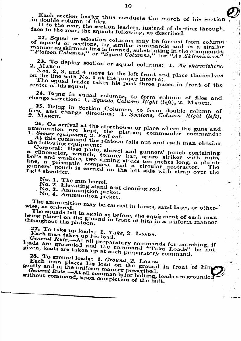
Each section leader thus conducts the march of his sectionin double column of files.
If to the rear, the section leaders, instead of darting through,face to the rear, the squads following, as dcscribed.
22. Squad or selection columns may be formed (rom c,?lu,mn'
of squads or sections, by similar commands and m a similarmanner as skirmish line is formed, substituting in the command~1"Platoon Columns," or "Squad Columns," for /lAs Skirmishers.
23. To deploy section or squad columns: 1. As skirmishers,2. MARCil.
Nos. 2, 3, and 4 move to the left front and place themselveson the line with No. 1 at the proper interval.The squad leader takes his post three paces in front of the
center of his squad.
2... Dcing in squad columns to form column of files andchange direction: 1. Squads, Column Right (left), 2. l\IAUCII.
25. Deing in Section Columns, to form double column offiles, and char~e direction: 1. Sections, Column Right (left),2. ~IARCJJ. ,
26. On arrival at the storehouse or place where the guns and
ammunition are kept, the platooI\ commandcr commands:1. Secure equipment, 2. Fall out.
At this command the platoon falls out and each man obtainsthe follOWingequipment: .
CC?rporal: Base plate, shovel and gunners' pouch c~mtaimnga clmometer, wrench, tommy bar, spare striker WIth nuts,~Its and ~'a8he.r8, two aiming sticks ten inches long, a pl~t;nbline, a pnsmatlc compn~, and a circular protractor. 1he~mners' pouch is carried on the left side with strap over theright shoulder.
No. 1. The ~n barrel.
NO.2. ElevatinK stand and cleaning rod.NO.3. Ammunition Jacket.No.4. Ammunition Jacket.
.The ammunition may be. carried in boxes, sand Lngs, or other-'W~ 118 ordered. ,
..ile "quads fall in ng3in as Lt~forc,the equipment of eaeh mn.ntlCmg placed on the ground in (ront of him in a uniform mannerthroughout the platoon.
27. To take up loac.llt: 1. Take, 2. IJOADI'1.
Jo.achrnan takrs up his lond.
I General RlJ.le.-At all pr('p:ustory cornmandlt for mo,rehing, if~a<Ltare Krounded and the command "Take Load~" bo notgIVen, 10a<Lt are taken up at such preparatory command.
2~. To KJ'ound loads: 1. Ground, 2. LOADI~. • •
:Each ma.n places. his load on the ~ro.und in front of hl!J'; firgently and an the unIform rnannrr rCII('ribed'J,Genn-al Ruk.-At aU commandli kr halting, loaus arc grou~de
Without command, upon Completion of tho halt.
L-...I
~
'

8/8/2019 Light Trench Mortar Drill Regulations
http://slidepdf.com/reader/full/light-trench-mortar-drill-regulations 10/40
11
PREPARE FOR ACTIOS
'29. At this command the corporal cxamines the contentsof his gunners' pouch, checks up its contents and makes certainthat tho clinometer is serviceable, after which he superviscsthe work of tho rest of hiiJ squ~d.Nos. 1 and 2 connect the elevating stand to the barrel and
plllco the gun in po~ition one (l) pace in front of the corporal,rnu~zlo of gun to the front. The traversing screw should becentroJ.
No.1 sponp;es out the barrel and rrplaces muzzle cover.No. 1, as~ilitcd by No.2, cxamineR the elevat.ing and travcrsinp;
p;<lIl.rs,emoves tho La:~ocap and in!lpects striker, being careful
to 8ee Ulltt it is screwed tightly in Lase cap and is clean, afrerwhich the haRe (lllp is replaced on the barrel.Nos. 3 and 4 look to their ammunition.After the examination is completed the squad takes post as
follows:
Corporal on left of gun in line with and facing the base plate.No.1 on rip;ht of p;lm in line with and facing muzzle.No.2, on left of No.1 in line with and facing the base plate.Nos. 3 anll 4 at the ammunition store which, for drill purposes,
is cOMidered M 5 paces in rear of base plate, facing the front.The corporal then reports ..N o. ( ) CORRECT" or otherwise,
tltating deficiencies. .
ACTIO~
30. At this command, the corporals run at double time outto their platoon commander and receive instructions as to target,method of fire, range, cllllrgc, fuze, etc. Details will be taken,down in a note book and will be repeated back to the officer~iving tho instructions. Each corporal, on returning to hisPORt, will communicate his inRtructlOns to his squad and thenduties will be carried out M follows:
The corporal aligns the base plate on the target by raisingtho bal'lOplat.e on its edge and si~hting over the upper edgeand movin~. tho LMo plate till it 18 accurately aligned on thetarget. Tho corporal th~n marks wh<'TCtho lower edge ofthe bRRo plato rests on the ground. This line f'hould point
directly toward tho target. Tho ba.~ plate is then turnedbottom sido up by No.2 and "laced on the ground with oneedge pltrallel to Rnll touching the line on the ftJ'ound. No.2then stands on the baRo plate to hold it firmly, whilo No.1marks around the four ed/l;cs of it with a pick or shovel. Thebaso plltto is then removed and the pit L'i dUll:by :\0. 1 within'the lines thuR mltrked out on the p;round. The pit when dugwill then hold the ba~o phto perpendicular to the target. Thepit should be V Ahaplld with the rear wall inclined at an angle of41)°. Tho top of the bn~o plate should be level with the surfaceof tho ground. Tho pit being dug, No.2 puts the ba.'io plate
tho pit with tho rope handlo upward~. It should be in firm"~~ontact with tho earth so as to prevent it shifting when the ~n
IS firod. The gun and elevatinll: stand are then placed in positIOnwith tho baso cap in tho central dl'pres~ion of the base plate.
'
" ~
8/8/2019 Light Trench Mortar Drill Regulations
http://slidepdf.com/reader/full/light-trench-mortar-drill-regulations 11/40
31. PREPARE (
12
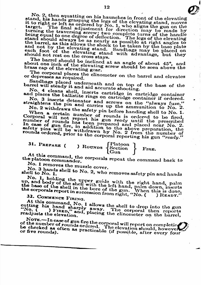
No.2, then squatting on his haunches in front of the elevatingstand, his hands grasping the legs of the elevating stand, movIesit to right or left as ordered by No.1, who aligns the gun on \;0target. The final adjustment for direction may be mnde yturning the traversing screwi two complete turns of the han.dle
being equal to one degree of deflection. The legs of the elevatmgstand should always be as nearly as possible at rill;ht angles tothe barrel, as this allows the shock to be taken by the base plateand not by the elevatin~ stand. Sandbags may be placed oneach foot of the elevatmg stand with advantage, but theyshould not rest on the cross stays.
The barrel should be inclined at an angle or about 450, andabout one inch of the elevating screw should be seen above thebrass cap of the elevating gear.
The Corporal places the clinometer on the barrel and elevatesor depresses as required.
Sandbags placed underneath and on top of the base or thebarrel will steady it and aid accurate shootmg.
No. 4 cleans shell, inserts cartridge in cartridge containerand places the l'allistite rings on cartridge container it ordered.
No. 3 inserts detonator and screws on the "always fuze,"straightens the pin and carries up the ammunition to No.2.
NO.2 withdraws the salety pin before handing shell to No.1.When a certain number of rounds is order~d to be fired:
Corporal ,'..ill not report his gun ready until the prescribednumber of rounds has Leen prepared and placed near No.' 2.In caso of gun fire, in addition to the above preparation, tho8afety pins will be Withdrawn by No.2 from tho number ofrounds ordered, prior to the corporal reporting his gun "rcady."
{
PlatoOn}) ROUNDS Section FIRE.
Gun
At this command, the corporals repeat the command back tothe-platoon commander.
NO.1 removes the muzzle cover.
NO.3 hands shell to No.2, who removes safety pin and handsllcll to NO.1.
No. If h~lding the ufP<'r guide with the rill;ht hand, palm
up, and l>Odyof the shel with the left hand palm down, insertsthe base of the shc~ in the ~re of the gun.' When this is don~lthe corporals report In sUCCCSSlonrom right, "No. ( ) READY.
31. CoWJdENCE FIRING.
A~ this .command, NO.1 allows the 8hell to drop into the gllncuttm~ h18 hand sharply away. The corporal then reports"No: \ ) }'InED,~' and, placing the clinometer on the barrel,readjUSts the elevatlon. .
NOTE.- In C8.'W.! of gun fire the corporal will report on complcti~!'of the numlX'r of rounds ordered. The elevation should, howeve~be checked 88 often 88 practicablo (if possiblo, after every fouror five rounds). ,
8/8/2019 Light Trench Mortar Drill Regulations
http://slidepdf.com/reader/full/light-trench-mortar-drill-regulations 12/40
13
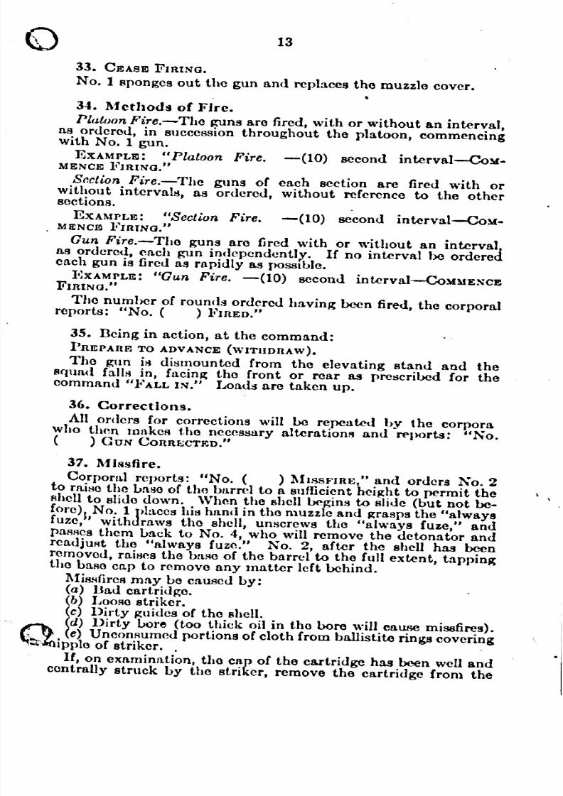
33. CEASEFIRING.
No.1 sponges out the gun and replaces the muzzle cover.
34•. Mcthods of Fire.
Platoon Fire.-The guns are fired, with or without an interval,as ordered, in succession throughout the platoon, commencingwith No.1 gun.
EXAMPLE: "Platoon Fire. -(10) second interval-COy.MENCEFIRING."
Section Fire.-The guns of each section are fired with orwithout intervalli, as ordered, without reference to the other
Bcctions.EXAMPLE: "Section Fire. -(10) second interval-Coy.
MENCEFIRING."
Gun Fire.-The guns are fired with or without an intervalas ordered, Mch gun indepcndcntlx. If no interval be orderedeach gun is fired as rapidly as pOSSible.
I;~XAMPLE:"Gun Fire. -(10) second interval-COMMENCEFIRING."
The number of rounds ordered having been fired, the corporalreports: "No. ( ) FIRED."
35. Deing in action, at the command:
PREPARETOADVANCEWITHDRAW).
Tho gun is dismounted from the elevating stand and thesquad falls in, facin~ the front or rear as prescribed for thecommand "FALL IN." Loads are taken up.
36. Corrections.
All orders for corrections will be repeated by the corporawho then milkeR t.ho necessury alterlltionR and N'ports: "No.( ) GUN CORRJo..:CTED."
37. MJssfire.
Corpoml reports: "No. ( ) MH.Sfo'IRE," and orders No.2to rahlOthe Laso of the burrel to a sufficient hci~ht to permit theshell to slide down. Wh<m the shell begins to slide (but not be.
fore)1 No. 1Jl1:l.ceshis hand in tho muzzle and ~rasps the "alwaysfuze,' with rnws the shell, unscrews the "always fUze," andpaRRes them Lack to No.4, who will remove the detonator andreadjuAt the lIalways fuze." No.2, after the shell has beenremoved, raiHcs the base of the barrel to the full extent, tappingthe LaROcn.p to remove any matter left behind.
l\fiRsfireRmay Lo caused by:(a) Bad cartridge. .
lb) Looso striker.c) Dirty guides of the shell.d) Dirty bore (too thick oil in the bore will cause miS8fires).
(1\ e) Uncommmed portions of cloth from ballistite rings covering~~ipplo of striker. . .
If, on examination, the cap of the cartridge has been well andcentrally struck by the striker, remove the cartridge from the

8/8/2019 Light Trench Mortar Drill Regulations
http://slidepdf.com/reader/full/light-trench-mortar-drill-regulations 13/40
14
cartridge container and insert a new one. If the cap is notcentrally struck, the fault is due to:
(a) Loose striker ..
(b) Bent or crooked cartridge container.
38. SUSPESD FIRI~G. •
At this command, the mortar will not he loaded or fired agamuntil command: COMMENCEInING, is given.
())
...
39. Moving the Gun.
Before moving the gun from one position to another the eleva-ting screw will be run down to its lowest extent.
1. Change Posts, 2. MARCIl (in action).
At the command: "Change Posts," the corpora~, remov~~pouch, places it on th~ ground. At the command: MARCIlhe takes Xo. 4's place.
No.4 takes No. 3's place.
No.3 takes No. 2's place.
No.2 takes No. I's place.
NO.1 takes the corporal's place.
This movement is executed at the douLle time.
40. On completion of the drill, Platoon Commander gives thecommand .
. 1. Replace equipment, 2. FALL OUT.
The equipment is replaced in store house or wherever it iskept, and at the command: "}i'ALL IN" the platoon falls in asprescribed. ,
41. Ammunition Jackets.
Four (4) per gun are provided to carry 4 shells each. Tho~acketa are put on Over the head and tho tapes tied over theJacket in front of the bOOyafter shells are in the pockets .. 42. Loading.
. The retaining pin of the "always fuze" or the lever of tho''pistol head" fuze should always Lo downward when insertingthe shell in the bore. .
U. Flrln4.
Betore firing, make Sure that all oil is removed from the bore.I~ the bore is oily, smoke will be given 01T and the position18Closed.
44. After Flrln~.
Examine, ,clean and oil all working parts. Examino striker.Clean and shl/;htly oil bore and remove all residue from chamber.Clean bl180plate. '.
Occnsionally KO over nuts and screws with wrench. To clca~.the bore of the mo~tar, inRert the bll.~eor the mortar
1wit.h th . ~I
bl180~ap remC?vcd, 10 a bucket of boiling water and t lell mRe~cleanmK rod 1O bore and move it up and down until Lore ISthoroughly cleaned. .

8/8/2019 Light Trench Mortar Drill Regulations
http://slidepdf.com/reader/full/light-trench-mortar-drill-regulations 14/40
15
o The strap and saddle frequently become loose thus permittingthe gun to FIlip forward durin~ firing. If tighrening the twostrap nuts docs not prevent thIS, it will be necessary to loosenthe strap nuts and then place a piece of tin between the strapa.nd the barrel, after which the strap nuts should again betJ/l;htcncd up.
The cross stays are arranJ1;edto spring just past the dead cenrerin sueh a manner as to hold the two legs rigidly apart. There isan adjustable lug on one of the crofl.~-stays to take up any wearwhieh may occur on the set pins. If the barrel is not 8upported •rigidly ~)y elevating stand, tightening the adjustable lug maycorrect It.
45. Muzzle Cover.
The muzzle cover should always be placed on the muzzle ofthe mortar when firing is not in actual pro~ss. In wet weatherthis is of flpccial importance as water 10 the bore seriouslyaffects the range.
46. There should be frequent drills with the respirators on,to accustom the men to handling the gun when 80 equipped.
8/8/2019 Light Trench Mortar Drill Regulations
http://slidepdf.com/reader/full/light-trench-mortar-drill-regulations 15/40
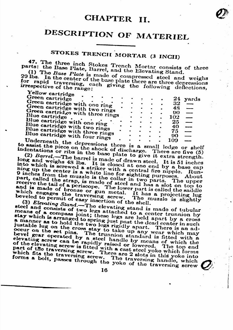
CHAPTER II.
DESCRIPTION OF MATERIEL
STOKES TRENCH MORTAR (3 INCH)
47. The three inch Stokes Trench Morta~ consists of threeparts: the Base Plate, Barrel, and the ElevatIng Stand. .
(1) The BlUe Plate is made of compressed steel and we!ghs291bs .. In the center of the bas~ plate there are t~ree depres~IOns
for rapId traversing, each gIVIng the follOWIng deflectIOns,irrespective of the raDge:
Yellow cartridge • . . . 24 yardsGreen cartridge . • . • 32Green cartridge with one ring 48Green cartridge \\;th two rings 90Green cartrid~f} with three rings 102Blue cartridge. . . . • 25Blue cartridge with one ring 40
Blue cartridge with two rings 75Blue cartridge with three rings 90Blue cartridge with four rings . 109
Underneath the depressions there is a small ledge or shelfto assist the piece on the shock of discharge. There are five (5
h
)indentations or ribs in the base plate to give it extra strengt .
(2) Barrel.-The barrel is made of drawn steel. It is 51 incheslon~ and weighs 48 lbs. It is closed at one end by a baso capinto which is screwed a striker with a central fire nipple. Run-
ning up the center is a white line for siKhting purposes. About{}inches (rom the muzzle is the collar in two parts. The upperpart, called the strap, is made of steel and has a. slot on top toreceIve the tail of a periscope. The lower part is called the Raddloand is mado of bronze or ~n metal. I t has a projectinK lugwhich engap;eg the traversIng screw. The muzzlo is slightlybeveled to permit o( easy insertion of the shell.
(3) Elevating Sland.-Tho elevating stand is made of tubularsteel and cOll8ista of two leKSattached to a center trunnion by
meana o( a compaas joint; these leKSare held apart by a crolisstay which is arranged to spring just past the dead center in sucha manner 88 to hold the two lep;s riKldly apart. There is an ad-justable lug on the cross stay to take up any wear which mayOCcur on the 8et pins. The trunnion standard is fitted with abevel .gear operate<! by a ."leel h"ndle by mcnns o! which IheelevatlD~ screw can be rapidly raised or lowered. 1ho top endo( the elevating screw is fitted with a cust steel yoke which formspart o( Ute traversing screw. There are 2 slots in this yoke into .
1Vhich fils Ihe Ira versing acrew. The Ira versing handle, which 1'1l'Conn. a boll, ra._ Ihroogh Ibo yoke of Ihe Iravorsing screw ~,
16

8/8/2019 Light Trench Mortar Drill Regulations
http://slidepdf.com/reader/full/light-trench-mortar-drill-regulations 16/40
17oand is held in position by a linch pin. A dog clutch on this boltcbngages with the screw and forms a means of traversing thearrei.
The ba!r~1 can be quickly disconnected from the mount~ng~YI first hftmg the linch pin and withdrawing the tr.ayersmgo t •. The barrel can then be freely lifted out of POSltlO~!or
car!"ym~ purposes. The bolt should be put back in poslt~onand h~Jd there by the linch pin. The weight of the eJevatmgstand 18 32 Ibs.
One. tur,n of the Traversing Handle will give t~e followingdeflection m yards irrespective of the range when usmg a
C
Yellowcartridge . • • . • • • • • 1~ yards
reen cartridge . . . • 2Creen cartridge with one ring . 3
]ceen cartridge with two rings 5~lJue cartridge. . . • • • 2Blue cartridge with one ring 2~BIue cartridge wit.h two rings 3~mue cartridge with three rings 5ue cnrtridge with four rings 6
TIlE TRENCII MORTAR SHELL
1148• The shell varies in weight but will average about 10 Ibs..oz. It is cylindrical in shape with a body m~~ of .cast steel
pa~nted a field gray or khaki. There are two distinctive bandspamted on each shell. A red band denotes a high explosi~e.A ~reen band denotes the sh('ll is loaded with ammatol, whi!ea pmk band denotes ammonal. The weight of the charge IS
2U los. The inside of the shell is thickly varnished to keep the
~xplosive dry. On each end of the body of the shell is a lathe-urned steel guide, made of very soft steel. Screwed or wel~ed~n to the bottom guide is the cartridge container, fitted With6 ~as escape holes. The top guide is fitted with a nipple screw
8R~dforms the entrance to the detonator well, a copper tubemches long.
II 49. There are two types of fuze! a time fuze, called the "Pistolend," and a percussion fuze, cal ed the "Always."
Pistol IIead.-This is an iron casting with two channels.1'he long one contains a striker and a strong steel spring. The810rt one contains a brass plunger and a copper creep 8prin~.On tho outside is the flyotTlever, one end of which is engaged 10
~~leneck of the striker, the other is held in position by the plunger.lere are two safety pins, one pn.s8ing through the long channel
an~ underneath the striker, the other passing through the plungerR?tJOn. Defore firing the pins are withdrawn. On shock ofdlscharp;e, the plunger falls down, overcoming the creep spring,thus releasing lever against side of barrel only. When shell leaves
}he !lluzzle, the lever drops clear, allowing the spring to expand,.l':\ orClng, the striker on the per<:ussion ca~, igniting the fuze,~e"ploding detonator and detonatmg the mam charge. .
. Dctonator.-No. 8 Commercial, containing 30 grains Culminateof mercury.
8/8/2019 Light Trench Mortar Drill Regulations
http://slidepdf.com/reader/full/light-trench-mortar-drill-regulations 17/40
18
Fuze.-Dickford's Slow Durning, 12)1 and 14 se? lengtl~Marked with dots and lines. Dots=H second. Lmes _.seconds. On one end is an Eley 410 percllssion cap in the sideof which are four small gas escape holes, through wl1ich the gasescapes through the hole in pistol head.
The 146 or "Always" consists of a hoIIow steel cylinder clo~cdat the top by a scrc~ fuze top, concave on the inside. I!lsldeare two pellets. The bottom one, made of brass, contams acentral fire percussion cap. Two creep springs are grooved ontop of the pellet and a small powder map;azine is underneatj,with sm.all gas csc!1PCholes on one side. The .top peIlet)s ma dof alummum and IS concave on top. It con tams the stnker analso has a small gas escape hole on one side. Hesting betw~(mthe two concave surfaces IS a steel ball. Fitting over the outs!deis a brass sleeve with an ejector spring. Fitting over the spr1D~and close to the sleeve is a small brass platform. Wound arOl~n(the outside is a waterproof tape with spring, on one end of whwhis a safety bolt which passes throllp;h the l)latform sleeve andLady and rests between the two pellets .. T 1e tip is held secureby a retaininR pin which enRages in Ihe framn nf Iho pialform
hs further safety precaution, a smull split pin passes througthe retaining pia.
Cartridge.-PropcWng charge: ballistite in Eley 12 borecartridge. .
Yellow cartridge contains 95 grains. nange 100 yds. to 220 yds.Green cart~idge contains 120 grains. Hange 116 yds. to 290 yds.Umg con tams 100 grains.
Green and 1 ring: 230 yds to 497 yds.Green and 2 rings: 287 Yds. to GOG yds.~reen and 3 ~ings: 340 Yds. to 753 yds.1he red cartridge, 175 grains, is no lonp;er used.
13I~e cartndge contains 95 grains bullistite, reinforced with5 grams ~n cotton yarn.
hlue rm~ contain 110 grains of 3 mm flake cordite.Blue cartrid~e: 102 yds. to 2,10 yds. .Blue and 1 nng: 197 yds to 420 yds .Blue and 2 rings 2.'>9Yds. to 550 ydsBlue and 3 rings 320 yus. to GfiO yus:BIue and 4 rings 36-1 yds. to 800 yds.
8/8/2019 Light Trench Mortar Drill Regulations
http://slidepdf.com/reader/full/light-trench-mortar-drill-regulations 18/40
e
'.. -::>.:\•
CIIAPTER III.
RANGE TABLE FOR 3-INCII STOKES
MORTAR WITII YELLO\V CARTRIDGE
50. PROJECTILE, WEIGHT, 10 lbs. 11 oz.
CUAROE, CARTRIDOE, YELLOW, SERVICE, 95 grs. Dallistite.
HINGS, 100 grs. Dallistite.
-._-. .-~-
YELI.OW CARTHIDGE TIME 'OF FLIGHT DEGREES
I- e
Yarus
220 7.0 45
210 7.6 50100 8.2 &5
170 8.7 60
I40 9.~ 65
100 9.6 70I
.;...- -'--_.
--.- -C- ....
IELLOW TIME YELLOW TIME YELLOW TIMEDE-
carLri(I/ote of cartriuge of cartridge ofGREES/one ring flight two rings flight three rings flight
- i
2.15 13.5 3.10 15.8 4S0 18 69
258 12.5 374 15.4 520 17.5 67
2nO 12 40G 15 555 17 65
318 11.5 4.10 14.5 .'j90 16.5 63
310 11 4S0 13.8 625 16 61
3115 10.5 515 13.3 660 15.5 58.5'
3nO 10 IHO 12.9 695 15 5-& .5I
410 9.5 574 12.4 730 14 48 I
---._- -_.--- . ----_. -"._--_. I
Noto.-Sce Orullunce Pamphlet No. 17401.
19
~
------
--
"-
- - ----
i
----- -- ---- ----

8/8/2019 Light Trench Mortar Drill Regulations
http://slidepdf.com/reader/full/light-trench-mortar-drill-regulations 19/40
20
RANGE TABLE FOR 3-INCII STOKES
l\IORTAR WITII GREEN CARTRIDGE
51. CUARGE, CARTUIDGE, GREEN SIo;R~ICE, 12011;1'8. Ballistite.RINGS, 100 grs. Sporting Ballistite.
-- _._ ..
NO RINGS 1 RING 2 RINGS 3 RINGStJ°
Timeime Time Timel.angl of Bight Ruge of flight Range of flight Range of flight
-f-
---f--
-Degs.
Yue. Sccs. Yue. Seee. YUIl. Spe8. YUll. Secs.45 200 7.5 497 10.3 660 12.6 753 14.050 280 8.1 487 11.7 6.t6 13.6 736 15.155 261 8.7 460 12.4 608 14.5 u06 16.157.5 249 8.9 442 12.8 581 14.9 6GO 16.660 235 9.2 420 13.1 550 15.3 636 17.061 228 9.3 411 13.3 537 15.5 621 17.262 222 9.4 401 13.4523 15.6 600 17.363. 215 9.5 3(J() 13.li 508 15.7 500 17.56-1 208 9.5 379 13.6 402 15.9 li73 17.66.5 201 9.6 367 '13.7 476 16.0 556 17.866 193 9.7 355 13.8 460 16.1 538 17.07 186 9.8 343 13.9 433 16.2 510 18.068 178 9.8 330 B.O 425 16:3 409 18.29 170 9.9 317 B.l 407 16.5 470 18.30
161 10.0 303 1-1.2 388 16.6 450 18.41 153 10.0 289 14.3 369 16.7 438 18.52 IH 10.1 275 14.4 349 16.8 410 18.673 135 10.1 260 14.4 329 16.8 39.i 18.77..
18.8
I 126 10.2 245 14.5 308 16.9 371I 75 116 10.2 230 14.5 287 17.0 3.t8 18.0-- ---
When ~ing. the Bickford Cuze, which may Lo 14 seconds oronly 12.5, It will be seen that a combination of Loth Yellow andGreen cartrid~es with rings will be necessary to obtain all thoranges up to 600 yards. •
The Collowing is suggested when using the PistollIead.
Rang\) 2fJ0--41O Yellow cartri(lge nnd one ring,375--475 Green cartridj!;e and one ring.
470-575 Yellow cartridge and two rings. .11'5ro-ooo Grecn cartridge and two rings. 't'" !
14 seconds Cuzeshould ho used Cor tho last two.
-= -
~ £
~ -~~
- ------
8/8/2019 Light Trench Mortar Drill Regulations
http://slidepdf.com/reader/full/light-trench-mortar-drill-regulations 20/40
e 21
RANGE TABLE FOR 3-INCII STOKES
MORTAR WITII BLUE CARTRIDGE
AND BLUE RINGS
{
CARTRIDGE, 95 grains ballistite, reinforced with
CUARGES 5 grains, gun cotton yarn. . .RINGS, 110 grains, 3 mm. Bake cordite.
-,h:"osi- Cartridge 2 RINGS 3 RINGS
0 1 RINGf::
only.i r
G).. II II
..Gl..<:l
Gl G)..<:lG) G)..<:l 1I..<:l lle
1I..<:l
!bII bII
II I
S.!1 S.!!PS.!f d S.!f S.!f d-g
-g
I&l-g
-g
foo- foo-fooCi
foo- g
00 0
- -- - --Degs. Yds Secs. Yds. Sec8. Yds. Sees. Yds. Sees. Yds. Seca.
45 210 7.1 420 9.6 550 11.6 660 13.2 800 15.0
50 233 7.6 411 10.4 538 12.5 649 14.3 780 18.2
52' 228 7.8 404 10.7 530 12.9 639 14.7 767 16.6
M 222 8.0 395 10.9 518 13.2 62lJ 15.1 748 17.0
56 2158.2
384 11.2 503 13.5 608 15.4 726 17.4
08 207 8.4 371 11.4 4~6 13.8 589 15.8 701 17.8
60 197 8.5 357 11.7 467 14.1 567 16.1 672 1~.2
61 193 8.6 349 11.8 457 14.3 554 16.3 656 18.4
62 187 8.7 340 11.9 445 '14.4 542 16.4 639 18.5
63 182 8.8 332 12.0 434 14.5 528 16.6 623 18.7
64 176 8.8 323 12.1 422 14.6 514 16.7 605 18.8
65 170 8.9 313 12.2 409 14.8 499 16.9 586 19.0
66 HH 9.0 303 12.3 396 14.9 483 17.0 567 1! 1
67 158 9.0 292 12.4 383 15.0 468 17.1 547 19.2
68 152 9.1 281 12.5 369 15.1 451 17.2 526 19.4
69 145 9.2 270 12.5 354 15.2 434 17.4 ~5 19.5
70 138 9.2 259 12.6 339 15.3 416 17.5 483 19.6
71 131 0.2 247 12.7 324 15.4 398 17.6 460 19.7
72 124 0.3 235 12.8 308 15.5 379 17.7 437 19.8
73 117 0.3 223 12.9 202 15.5 360 17.8 413 19.9
74 100 9.4 210 12.9 275 15.6 340 17.9 389 20.0
75 102 0:4 197 .13.0_ 259 15.7 _~20 18.0_ 3~ 2O..L-=:- .... --_.-
If it is essential to get a 700 yard ran~c, this can be doneb.y firing at 45 degrees clevation, with Green cartridge and
t iree rinKS.
The short ranges, with 1, 2 or 3 rin~, should be avoided
t?..s far as possible, as the s.~e!l gocs 8<? I11gh that it is affectedV much more by weather conditIOns and 18 not accurate.
AWind affects the ran~e, when using rings, very considerably.high wind behind the shell increases the range and shortens
f!/sr1.~ :>
~ ~ ~ ~
~ ~ ~ ~ ~~ ~
__ __ -

8/8/2019 Light Trench Mortar Drill Regulations
http://slidepdf.com/reader/full/light-trench-mortar-drill-regulations 21/40
22
the time of flight, enabling ranges to be obtained,_ whic~l otll~iwise would be impossible. A wind blowing agamst t 10 S 1.has the converse effect.
LAYING TilE MORTAR IN DIRECTION BY TIlE USE
OF TilE AIMING STICKS
52. With the aid of the periscope the corporal direets No.lto plant two aiming sticks in the parapet in hne with the ta?k~The one nearest the target should be planted first. The s lC dshould be separated by a distance of from one to two feet anshould firmly driven in the ground in order to prevent an~shift in their position. Care should be exercil'led that theRe iW0sticks are planted in such a n.anner that tho target and the rWnsticks lie on the same straiJ,!;ht line, and that the prolong;a ~}0of this line passes through the position to be occupied by Imortar.
PREPARATION OF TilE RANGE CARD
The mortar bein~ in position, and having registered on thetarget, the aiming sticks are altered, if this is found necessary,until the prolonJl;ation of the white aiming line on the morta~passes through the two aiminp; sticks and interseds the r!!trlmportant tar~et in the sector allott.ed to the trench mortar. 10
two aiming sticks then determine the zero line of the range card.Mark the position oCthe mqrtar by a smull circle at ~l!e botto1medp;eof range card. Draw a line Crom the mortar position to t 10
pr!nc!pal target, indicated by the aiming st.icks, a:nd labelthiS line the zero hne. Having already registered on thiS tar~et,mark, on zero line. the elevation and cartridgo used. For ot IC{tar~e.ts in the scctor, register on them in turn, and from e!1c1P081ti~n of the mortar when reJl;istered return it to tho zero hnc,countmg the turns oCthe trnvcr8in~ handle or tho movementsoC the base cap in the base plate traversinll; and convert thesochanges into yards. On the range card draw lines from ~homortar positi.on in the direction of tho v~rious targcts, labe~lllP;
them by ~helr. target designations, and mark along theso hnesthe elevation 1~ degrees and tho cartridll;O used. In tho anjl;lobetwccn these hnes and the zero line write tho numher of yardsof travcrse. Whcn completed, the ranjl;e card should be inclosed«(or wa~t of something bettcr) in a picture frame with a glassf~cc, which can be purch~d for a few cents at a storo near thobilleta. .The gll188(ace on the picturo frame will prevent thodestruction of the range card when using it in tho ralll.
USE OF RANGE CARD
53. Align mortar on zero line, with the aid of the aiming sticksplanted in the wall of the parapet.
The mortar being in this position, the firing data can bo takenl1~at once from the range card. . ..1
11ms, with a ranp;e card, the mortar can be prepared for firing
~
~
~

8/8/2019 Light Trench Mortar Drill Regulations
http://slidepdf.com/reader/full/light-trench-mortar-drill-regulations 22/40
o 23
farm Hou!.e
7'oint Ironl: which made out .
111ade by.................................................... Dat e .
Not cs~ .
•••••••••••••••••••••••••••••••••••••••••••• ll, ••••• ••••••••••••••••••••••••••••••••• •• •••••••
LAYING TIlE l\IORTAR IN DIRECTIOS BY CO:\IPASS
54. 1. Loeat,e on the map l1Ccurately the gun position of the
mortar.2. Locate on the map accurately the exact position of the
~arget. If the target is a linear one, take the central point of the
argot fl:S the objective.
3. Draw a line on the map from the gun position to the target.
tl4. Plltce the ccnt.er of the protractor on the gun position on
lie map and reau the numhers of Ul'grees from the north to
t Ie target.5. Correct'for tile local magnetic variation of the needle.
6. Drive in 'one of the aiming sticks at the gun position andplace the compass on top of it. Hotate the compllSS till the cardreaus the requireu magnetic hearing and drive in the otherstake on the wall of the parapet, it having the magnetic bearing
of the target. The two aimmg sticks then determine a line tothe objective, from the mortar pOl;ition. Align the mortar onthe two aiming sticks by holding the plumb bob and line over
... ,}l~eear stake and bringing the white line on the mortar in line'V"lth the front stake and line of the plumb bob.
This method will be the only method available in the eventof an advance where the mortars will be required to go intoaction within the enemy's former lines and to open fire without
' ~ - _
~ ~
8/8/2019 Light Trench Mortar Drill Regulations
http://slidepdf.com/reader/full/light-trench-mortar-drill-regulations 23/40
24
delay on a target which an inspection of the map will show to beinvisible from the position selected for the mortars. The nCdc~fsary firing data can be computed prior to the advanc~ anfi 1
accurately performed there will be no delay in openm.g rdhis method is valuable also in night firing on an unregH~tcrctarget, and by daylight where the target cannot be seen fromour lines, but can be located on the trench map.
55. Method of Testln~ the Compass.
The compass used by the trench mortar detachments ~ustbe a good instrumentl prismatic or equivalent t~eret.o. Evchngood compasses are liable to have an error. The duectlon of t e
magnetic north indicated by the compass needle may no~ ~othe actual magnetic north, but this error is of no account. ifd1tbe a constant error in the ~ompass reading and if its magmtu 0and sign be known. •
To test the compass, proceed as follows:From an accurate map select two points, both easily detcr~
minable on the ground and reasonably far apart. Jam thesopoints on the n.ap by a straight line and, by knowing th~ lo~almagnetic variation, determine the magnetic bearing of thlslin~on the map with the protractor. Proceed to the ground anread several times the bearing indicated by the compass f~omone of these objects to the. other. The means of these read.mg
dhould agree With the magnetic bearing of the line dcterJ!1mefrom the map. If it does not, the difference between them IS theconstant error of the compass which will thcreCore read toomuch or too little as the case may be.
EXUfPLE.-From map, bearing of church from crossroads
equals-84 degrees; .Dy means of compass readings, bearing of church Crom cross~
roadlt-85 degrees. .
Compass error-l degree too great .
. The compass is commonly uHCdby the trench mortar squaJ8~either for resection or for laying in direction, and a ~nowlodgoof the ~rror of the comp3..'lSwhen perCorming theRe dutlCs caD •conveDlently applied in either one of the two following ways.
1. ~nvert .the bearings given by the compass into tho tru~magnetic beanngs (by addinK or subtracting the error) and worfrom the magnetic Nand S lines on the map.
2. Alter the local magnetic variation shown on the map byth~ plt;tsor minus error of the compass. A local magnetio. varl~atlon 18 thus obtained, suited only for work with the rartlc~larcompl18Swh~ error has been determined; consider al bea~mg~taken by thls compass as being correct magnetio bearmJt
donvert. these. L«:aring.,to
true North bearings by use of the alteremagnf'tIc vanatlon8; work from the true Nand S lines on the map.
TIle compM8 should not be used when the iQstrum~Dt iscl.o.:'C. to steel or iron. It 8hould therefore not be used 10 theVICIDltyof the mortar or ammunition and the user should Dothave metal on his person such as a re~olver. Jl1). It is impossible to say what distance the mortar and ammun~>tlO~ should be removed from the position of the compass, but
~
8/8/2019 Light Trench Mortar Drill Regulations
http://slidepdf.com/reader/full/light-trench-mortar-drill-regulations 24/40
o 25
56. Resection.
po~~.Rcction is a method of locating accurately on the map the
;1 lon?f ~~y point chosen on the ground. .tC8cctlOn IS useless and unnecessary in tile followmg cases:
1. When the map is inaccurate. .102'
t'Xl~cn the map is accurate in detail and the positi<:mto be
o~~he IS near any object which it is possible to identify bothe map and the ground.
t13. When the map has the trench system marked accuratelylereon.
Resection is necessary in the following case:10When. the map is accurate in detail, but the position to bethcated 18not near any object which can be identified both on
e map and the ground.
57. To Locate a Point by Resection.
On(~~ Select three prominent points on the.lands~ape, markede map, and roughly 120 degrees apart, if pos.'nble.
Ii (b) Determine the magnetic bearing of these points and draw
nes through them', backward until they intersect ..int(c) Th~se lines (if the map and compass be accurate) will
crsect 10 one point, which is the position required.
CD \

8/8/2019 Light Trench Mortar Drill Regulations
http://slidepdf.com/reader/full/light-trench-mortar-drill-regulations 25/40
CIIAPTEH. IV.
DISK SIGNALLING
58. In working with l,ombers, a ra\,id and very simple mc,th~~tof signal cbmmunication is requirel. One of tho vest sIgn.code8 that has Veen tried is on the following lines:
t1. The ohserver to carry a small circular metal disk al~ollo1.5 feet in diameter attached to a polo about 4 feet long. r ~odisk i~ to be painted with rell and green quarterings on one
d
f:1c f
and black and white on the other. The disk can be ma 0 0
wood and canvas.
SIG:'IlALS lOBE AS FOLLOWS
59. Range: Signals for range will be given with tho dis~raised above the head, red and green quarterings toward th'reader.
Increase rangp 10 yards: Lowered onco to the rigllt.
Range correct: Dil'lk held in the vertical position for 11 fewseconds. . . . J
Line: Signals for din'ction will he given with tho disk rdal~l0above the head with Llack and white quarterings towar I
reader.
Right or left 10 yards: Lowered ollce to tho right or left.
Line correct: Dil'lk held in tho vertical position for 11 fewseconds.
60. To stop the fire: Disk raised in 11 vertical pO.Hition, .re:and green toward the reader and waved rapidly from tlldo to filii.
To infor~ infa!!trr .commandc~ that ~l~o fire. has liftcil ~Istopped: Dls~ rlUSCI In the vertical pmntlOll, With LI:tck at 1white quartermgs toward the infantry commander and waVelrapidly from side to sille. .
61. In using these la~t Ril;nals Rince several shells will 1,'0 ilithe air, a few 80conl18 should be ~llowell after giving tho BIp;1l11
to the p!atoon, hefore giving tho signa'l to tho infantry coJll~mander, If our mfantry are to rush tho trench.
NIGHT SIGNALS 1
62. At nig.ht, disks paint<;d w,ith luminous pai!!t may. be ~Hc~l~or torches WIth red and wlute lights, a tuhe 12 mches m longsupplied to go over the torches to shade tho flash.
R~l.-()ne dash=Lcngthen 10 yard~.
Dash dot dash=Hange correct.
A BCrif:'sof dots=Stop firing (to mortars).
JrJdle.-onc dash=Right 10 yards.
Dot dash=I..eft 10 yard~.
Dash dot dash=Linc correct. #1A 8('rics of dots=Firc has bt~cn stopped. ~9

8/8/2019 Light Trench Mortar Drill Regulations
http://slidepdf.com/reader/full/light-trench-mortar-drill-regulations 26/40
o 27
Buzzer and Shutter Signals
m 6J. The follo~ing signals should indicate the corrections to bea e, not the location of the strike of the shell.y ~l sill;nal corrections for laying the mortar will be made inar s of 10 or some multiple of 10. .da~l(t.-one dot for every 10 yards correction, followed by a
E~AMl'LE.-Lcft so yards.t ll~(lht.-One dot for every 10 yards correction, followed by
~d~~. .
EXAMPLE.-Right 20 yards.c lcnglhen.-One dash followed by one dot for every 10 yards
orrection .
. EXAMPLI~.~Lengthen 30 yards.
C
Shorl.en.-Two dashes followed by one dot for every 10 yards
orrectIOn.
EXAMPLE.--8hortcn 20 yards.
Rcgislcr.- ..• , dot, dash, dot.UeceilJcd.- .•. , one dash.
Repcal.- ... , two dashes.
-

8/8/2019 Light Trench Mortar Drill Regulations
http://slidepdf.com/reader/full/light-trench-mortar-drill-regulations 27/40
CHAPTER v..
l\IETHOD OF BRACKETING
64. Estimate the range to the objective. Add 30 yards to the.estimate. Lay the mortar at this ran~e and if the shot goesover the target the next shot should be fired with the mortarset at 30 yards under the estimated range. If this shot falls shor~
the target is within a bracket of 60 yards. Halve the brackeuntil the target is hit. If, in the first place, the mortar wasfired at the estimated range it might be very difficult to tellexactly where the shot struck. In some cases it will be necessaryto use two observers when firing at a small target such as amachine gun emplacement where the direction and rango ar~~th important. In such a case, place one observer in the frondline between th" mortar and the objective who would ~enback information right or left, so many yards, as the case mIght
be. The other observer should be placed on a flank and observethe range, sending back the information to lengthen or shorten80 many yards. '.
EXAMPLE OF REGISTERING
65. Mortars at approximately the same range from tho target.Target-line of trench. .
7- 7-0l:J 0
E:: tll
E::::Idi < >.c:l
Z~ <z~PLATOON COMMANDER'S ORDERS'0 '0 0-1 m+
0
1
2a
46
e78
o1011
1
11
11
1
2a46e
Y&rt:fa TARGET-LINE OF TRENCH
300 No.1 Mortar, Range 300, CartrldK_FireNo. I.
400 ,Ran~e 400. Cartrldl(e-Fire No. I.' •12 tllTnl Left, Range 380, CartrldlCe-FlJ'e
No.1.400 RanKe 400. Cartrldlte-Fire No. I.
380 IR"nKe 3/W, CartridlCe-}<'ire No.1., 'Platoon. Hange liMO. Commence.390 n ) ,'}<'ir.,20 180. Interval, CartridKe-l<'irinl(.3!l() n .3'J() l==- No.3. two tum. lolt.
!~_~__J::~:;;~ree turnaright~ .__
~ ~
~ ~ ~ ~
~
~ I.

8/8/2019 Light Trench Mortar Drill Regulations
http://slidepdf.com/reader/full/light-trench-mortar-drill-regulations 28/40
NOTES
t The first found, which was expected to be over, was foundThbe short. The platoon commander therefore added 40 yards.
W't8hthird round gave a bracket of 20 yards, which was verified1 rounds four and five.
\)29
EXAMPLE OF REGISTERING
ON A HOSTILE TRENCH,
CLOSE IN FRONT OF OUR OWN INFANTRY
66. Position of platoon, about 200 yards behind our front line
-_._.,-------_ .......---_.._.. ~--,-_._'_.-
Z
"l:l:r. 0
o0 e::t-g
o-g e:: < ;'.t2
Z~ Z~< ~!f
PLATOON COMMANDER'S ORDEn..,
,I>
'0 '0I.;j Pl
0
+60
250
YardsTARGET-LINE OF TRENCH I
. . I
No.1 Mortar, range 260, Cartridge-F~
No.1. I2 turns right. range 200, Cartridge-Fire
No.1.240 RanlCo240, Cartricllte-Fire No.1.2:l0 RanKe 230, Cartriol(e-Fire No. 1.240 HAnl(e240, Cartriolte-Fire No.1.230 Hanl(o 230, Cartridge-Fire No.1.
230 { Platoon; I I R.a 230 cComif'nre'
.Ii ~__::~.n_. n.. · ~ OJ
1
1
(1
11
1
23466
1
2
34
6,6
7
uiIn the above case it is not advisable to use bracket systemon account of the proximity of our own infantry. The Platoon
fIommlluder intentionally overestimates the range, and adopts
1e "creeping" method of ranging.
---=-- --- ~---
~ ~
~
l

8/8/2019 Light Trench Mortar Drill Regulations
http://slidepdf.com/reader/full/light-trench-mortar-drill-regulations 29/40
Chapter VI.
STANDING TRENCII ORDERS
Duties of officer in char~e of squads in trenches
67. 1. Put himself in communication with CommandingOfficers and state position of his headquarters.
2. Visit all emplacements. Instruct and question elwh gun-corporal as to his duties. h
3. Prepare range carus and ammunition re,)orts for c?'loemplacement, if not already existin~, and he wil be r~spollslb tthat the latter are written IIp before submitting his ually repOfof expenditure oCammunition. .
4. lIe will also see that the oruers detail'ed below for N. C. O.'sare duly oLeyed. '.
5. lIe will vi.'lit the emplaeements twice by da.y and tWlC~
between morning inspection and eveninp; inspection to seo thlthe gun teams are on the alert. 1Ie will daily causo corpora S
of the guns to repeat to him their oruers.
NoTE.-orders for every gun will be posted in cach emplace.ment.and be the direct orders of the platoon commander. ~nyaddItions or amendments considered necessary by any OfIlCerof the unit will be made thereto, bearin~ his initia.ls to be count?r-signed daily by the platoon commander or sanction otherwlf~eaccorded in wrlting.
It is believed that. the second line, suh-'para~r~ph 5, parap;.royh67, should read "hnco between evening inSpectiOn and mOlfilnginspection."
6. lIe will inform company commanuers before he fires 80
that tho former may Ret their men under cover. if nccesfmry.T~is applies both in retaliation and ofTcnsivo firo.
Duties of a Ser~eant ,68. 1. This N. C. O. is immediately reRpollsiblo to the officer
in charge of the line.
2. lie wil~ a.'iSume the powers of the Platoon Commander,when anythmg unforeseen or extraordinary occurs from. thoel!emY~8Cront, until the officer in ChllfJ~Cs able to commumcatoWith lum and approve or countermand his action.
3. The officer in charge will be locate(l if pm~8ible,loft of the
right section and tho sergeant center oCthe left scction, shouldconditions permit it.
4. lie ~'ill visit, ~'ith the office~ in chnrge, .tho gun cmplac?menta dally and at Intervals Ly DJll;ht. IIis DJghtly roundli Wlllnot Le made \\;th the oflicer unless 80 directed and normallyflhould consist of two visits. 0
30
'

8/8/2019 Light Trench Mortar Drill Regulations
http://slidepdf.com/reader/full/light-trench-mortar-drill-regulations 30/40
31
. 5. lIe will immediately bring to the notice of the officer in(,harge any want of discipline or alertness on the part of tbo
sentries on the guns.
?utles of other N. C. O.~sof guns
69. 1. To see that sentries are posted between evening in-sp(\ction and morning inspection.. Sentries consist of one. (.)~. C. O. and three men, constitutmg one gun team as provided
In trenches.2. That his gun is cleaned by 9 A. M.
3. That all ammunition is cleaned.4. To daily write up and initial the ammunition report.
b
5.. 1.'0 report to bis nearest officer anything of interest observed
y lam.
WilEN TAKING OVER FROM: A PLATOOS
70. Upon receipt of Operation Orders the platoon commandersho.uld, the day prior to takin~ over, visit the platoon commander
he IS relievin~ and personally ascertain the following particulars,and satisfy himself that the statements made to him are not inany measure a misrepresentation of existing facts and conditions.
Points in particula.r to be noted: ~.
1 f
(a) If the outgoinp; unit is in pOS8Cssion of any information
e t behind by previous units holding the line.
t}
(b) If the outgoing unit possesses any information or notes
lat may be of value. I
«C) If a defense scheme will be handed over.d) Maps to be handed over:1. Air photographs.2. Local trench ml\pS of zone.3. Trench maps of actual sector to be taken over by brigade.
, 4. Maps of enemy's trenches.(e) Ammunition to 1>0 handed over and ammunition state-
ment demanded.U) Men's billets to he carefully inspected.
b.. (0) Cooking facilities and water supply in trenches and inIllets. .(h) Method of carrying rations to trenches.(i) Personally accompanying the C. O. around the trenches
and ~otc particularly: •
1. Tho maximum and minimum distances betwccn trenches.2. Check contours of our trenches against trench map.3. Inspect enemy's front line with aid of periscope, always
from observation POl:ltsand sniper's posts when allowed.
4. Visit all emplacements. Ask for range cards with eachel,mpla.cement, if any, or otherwiso actual sector or enemy's
Ollie or postcovered.
t L) In thill oonnection loo"tion or oondition of brilt"de and divillional dumps
t~ y~:;o~~t~tt~f~;'~:~~m:tio~.nYrrciullU'iti61 noted here ~o be mCDtioDed

8/8/2019 Light Trench Mortar Drill Regulations
http://slidepdf.com/reader/full/light-trench-mortar-drill-regulations 31/40
32
5. Ask for ammunition card at each gun emplacement andiQspect to see if written up.
NOTE.-Range cards and ammunition statements must be
kept at each emplacement. The advantages are that theyfacilitate reliefs, daily inspections by the C. O.'s and officersin charge of the trenches.
6. Inspect ammunition, noting the following points particu.larly.
(1) That the cartridge is not damp; as it may occur that'while the cap end of the cartridge is dry, the wad end may bedamp and, necessarily, this will have the effect of the shell dro~.
ping very short at times, probably to the disadvantage of t ~eInfantry holding the line. The explanation to be offered for tIllSis that the full charKOdoes not simultaneously explode when thecap meets the striker.
(2) That the gas escapes of the cartridge containers are clean.
When Turning Over
See that aU you have required when taking over has beendono by you.
AMMUNITION REPORT
_._~------_
lit
IIIQ
:~ III
li 80 <-0
j;j~-oAT. Il (
D&SCRIPTION ~.~ o~ RItMARKS0 0 Il(ii;
a;zu z 0
ZI-
I 27/10/17 360 60 cartri<l1l1l8 200 1000 100 is Roun,!s unfit (or firing
128/10/17salvaged J. M. Lt.
255 Do. 150 800 60 All clean 60 rounds re-ieoived J. M. Lt.
12WIO/17 250Do. 100 700 All clean J. M. U.
-.--
..- ------ -
-
~ I
-------------
--

8/8/2019 Light Trench Mortar Drill Regulations
http://slidepdf.com/reader/full/light-trench-mortar-drill-regulations 32/40
CIIAPTER VII.
TIlE USE OF TRENCI-I l\10RTARSIN DEFENSE
72. Trench mortars have the following uses:1. To destroy living targets when the opportunity is presented.2. To destroy all defensive works and obstacles.3. To prevent the construction by the enemy of new works .
. 4. To drive the enemy from small scctioll8 of our trenches
In which he may have gamed a footing.5. To bombard important points in rear and on the flanks
0d f a section of the enemy's line, thus isolating him while he is
calt with by our infantry.
73. The use of trench mortars in defense will be considered
dunder three headings, (a) Holding the Line; (b) Offell8iveefenRive action; (c) Counter-attacks.(a) Holding the line:~very unit in the line has a defensive scheme. To prepare
thiS Bcheme, one must study all the maps, aeroplane photographs,enemy's trenches, etc. Then decide on what part of the lineneeds trench mortar assistance the most. There are alwayscertain points where they are most useful such as salients wherethe two lines are very close together. The front lines now very
fTrequently consist of shell craters, connected up, forming posts.rench mortars can protect the intervals between these posts.
~n selecting sites for the trench mortar emplacements the follow-
mg points should be considered:
1. Range of the mortar.2. Cover from enemy's fire and view.3. I~ossibilities for observing the fire.
{
(I) Between mortars and observing
station;4. Communication (2) Between mortars and trench gar-
rison.(3) Between different mortars of platoon.
5. Condition of soil as regards drainage.(1) The ranue of the mortar is between 100 and 750 yards.
If the mortar IS placed in the front line it mar be lost duringthe enemy's barrage prior to his attack, which 18 always placedon front line. The best location for a trench mortar is about
200 yards in rear of the front line, for the following reasons:The ammunition supply is eaHicr; it hM a greater accuracy offire, because it can then be fired at or near 45 degrees, which is
the most accurate elevation. Also it is in a. better position to: .ssist. in a counter attack on an enemy who has penetrated our
hrst lme trenches.
33
~

8/8/2019 Light Trench Mortar Drill Regulations
http://slidepdf.com/reader/full/light-trench-mortar-drill-regulations 33/40
31
(2) Cover from enemY'8 fire and view: An ideal position is onein dead ground with a dark background such as a wood. If th
dortar is in dead ground it cannot be seen br the enemy an
if it has a dark background tho li~ht of the shel from the mor~arcannot be seen till it is well on Its way and thus will not gIve.away the location of the emplacement .
• (3) Observing fire: Points in our own front line should 1,0 note,don trench map, {rom which the cfIects of your fire on the enCI~Ysposition can be observed. It is important to note thes~ pomtson the map 80 that if you get hurried orders to sheIla bIt of thoenemy's trench you will know exactly whcre to go to observeyour fire.
(4) Com'munication: There must be always communicationbetween your infantry in the trenchcs, with your observersand with the sections of your platoon. This is generally accom~plished either by buzzer, signals or runners.
(5) Drainage: Emplacements should not be ~elected .inr.laccs where the pits will fill \vith water during a heavy ram.fhat is, they IrllUlt have a drainage outlet.
(b) OjJensive-dejensive action:
Normally a trench mortar platoon keep!'!half of its per!'lon!1elwith the gun and half resting in dugouts, one half work~ng durmrthe day and the other half durin~ the night. In FlClectlll{.trenc 1
mortar emplacements avoid mam communication trenches, aswell as main trench systems, as these are always heavily shelledby the enemy. After having selectcd emplacements, dig the
hnd prepare Cover (or men and camouflage. Then give e.acmortar a definite Rector of enemv's line, noting im{>ortant pomtswithin sector. Having allotted sectors and objectives, thenre.gister. This is acc?mplished by aO,tunlly firing at U.le targetWIth observers watchmg (all o( ahots till exact range IS found.After registering, make your range card. When registering,do it incoIl.'lpicuously so enemy will not know it. Fire ono mortarat a time With a long time interval.
In each emplacement there should he standing orders as to
"'hat the squad should do in all events that cnn bo foroscen ..}'or example, when the enemy's bnrrap;o is on your front linCH,)'our mortars cannot fire. Tho moment it lifts to tho rear thenIt is time to destroy his attack. In n gas attack always fire onthe enemy's (ront line.
RetaliaJ.iJJn: The enemy will empty his front trenches and put~i8 !flen in d~p ~up;ou~s and then open fire .. If you retalu.tteIt wdl. only be ap;~mst 111$ empty trenches. It IS a bet~er polley
to walt and retalIate When he 18 not ready for it. It 18 alwaysbetter to ~llve an orp:anized retaliation, such as, artil~ery, trenchmortars, rifle grenades, etc. Destroy a section of hIS trenches.Whenever an artillerf bomhardment of the enemy's trenchestakes plar.c, always jom in with your trench mortars.
Rau 0/ fire: I..ay down the type of fire to bo usod in cltc1memergency, othenn::lO all tho ammunition may bo used up an(~:;.none on hand when most neednd. A general rule, tho longer

8/8/2019 Light Trench Mortar Drill Regulations
http://slidepdf.com/reader/full/light-trench-mortar-drill-regulations 34/40
. 'Ammunit'ion: There should always be at least 100 roundsof ammunition in each defensive emplacement and 100 roundsper mortar in reserve 300 to 400 yards in rear of emplacement.
When the epemy puts on a he!l:v>"bom~a~dr,nent it will be outof the questIOn to get up ammumtlOn while It ISon, and wheneveryou think you may be going to withstand an attack, get all the!tm~unitioll up you ean lay your'hands on and trust to luck thattt Will not be destroyed ,during the bombardment. :rhere should
N
JCa reserve store for no more than two mortars 10 onc place.
ever have a reservc store for a. platoon-in one place.. Emplacements: There should be several emplacements con-structed for each mortar. These, to be used 10 annoyin~ thc
enemy, might consist in widening a communication trench orcertam places in the front line, but there should be one permanentemplacement constructed into which you go when the. encmyPt~ts down on you a great bombardment and (rom whICh youwill use the mortar in repellinJ7;his attack. This empl.acem
cnt
should only be used in the registering and in emergenclcs. Thei~tcrnative emplacements are u~ed to annoy enemy, destroy
U8 personnel, and inflict losses upon him.
(c) COUltlcr attacks and local attacks:I,n raids, whenever possible, the mortars should be used toaARIAthe bombing squads. They should be 80 placed that theyCan bring a heavy concentrated and continuous fire on a. pointJlreviously fixed in the enemy's trench about fifty ;)'ards Ue).ond
the length to be secured by the bombers. .r~he position of tho mortars may be either in the trench down
wIuch the bombing raid is made so as to give enfilade fire or in the
trenches opposite to the objective.
The following points should be attended to by trench mortarofficers:1. Careful registration on target before operation takes/lace .
. 2. Fire should be opened at the moment of attack an con-tmued until the objective is gained and consolidated.
b
3. A plentiful supply of ammunition should be at the mortars
cfore the attack commences.The trench mortar can also be used to fire ahead of bombers
as they proceed down the trench, but this method should only
be employcd when obscrvation is SO favorable that tho trenchmortar officer cnn make certain that he can follow the move-
ments of the bombers down the trench.
EMERGENCIES
74. Whatever precautions are taken, the circulation of ordersamong t,rcllch mortars will always be ditIicult, and at times ofsudden emergency very precarious. Every member of a trenchmortar pll~toon must be carefully informed of situation8 likely
to ariiie an,l, in addition to other situations, must know be-forehand exactly what he is going to do, and what action the
. platoon will take in the following emergencies: .
1. Gas attack on the front.V 2. Sudden hostile bombardment.
3. Mine cxploRion.4. Trenches rURhed-
'
"'"

8/8/2019 Light Trench Mortar Drill Regulations
http://slidepdf.com/reader/full/light-trench-mortar-drill-regulations 35/40
36
.~
The course to be taken depends in almost every case upon ~heaction of the infantry. A close understanding must be had wIththe infantry and common action decided upon beforehand.
MAPS
75. Every trench mortar platoon commander should keep amap showing: .'
1. All emplacements with their arcs of fire.2. All mortars in action, with their night lines.3. All emplacements in the process of construction.4. All observing stations, showing exact field of view from
each.5. Ammunition stores, showing routes of supply from each.6. The Platoon Headquarters. .
All maps should be kept up to date and handed over to thorelieving units. .

8/8/2019 Light Trench Mortar Drill Regulations
http://slidepdf.com/reader/full/light-trench-mortar-drill-regulations 36/40
37
TYPE OF TRENCH MORTAR POSITION
\.,
NOTES:
The extent of front to be covered by the mortars is from A to nbut concentrated fire is required on the salient and craters.The mortars are so placed that each mortar section except
No.1 can cover the salient, and so that all mortars enfilade eitherportions of the enemy's front line or communicating trenches,while the fire of two sections can be crossed if neccssn.ry.
o
8/8/2019 Light Trench Mortar Drill Regulations
http://slidepdf.com/reader/full/light-trench-mortar-drill-regulations 37/40
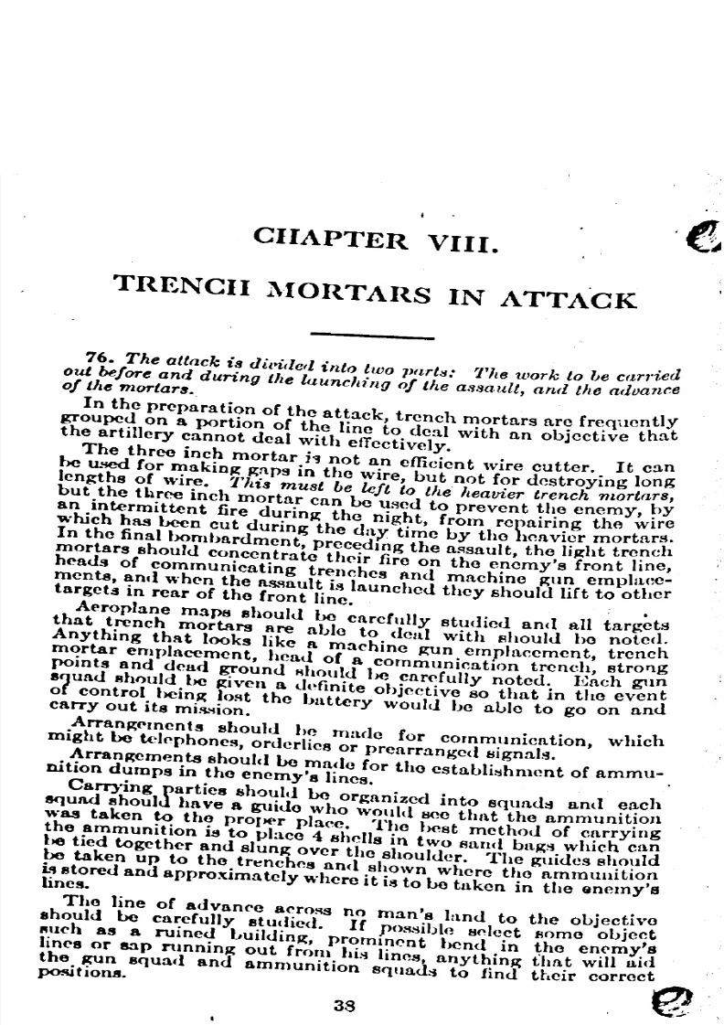
CIIAPTER VIII.
TRENCII l\fORTARS IN ATTA'CK
76. The attack is diltidcll into two parts: 7'he work to ')e carried
out be/are and dUring the launching 0/ the as/wuli, and the advance0/ tIle mortars.
In the preparation of the attack, trench mortars are frequentlYtrouped on a portion of the line to deal with an objective tha
the artillery cannot deal with etTectively.
The three inch mortar h not an efficient wire cutter. It canbe u.'!Cd for makinJl: Jl;npsin the wire, but not for destroying longlengths of wire. 7'his must be left to the heavier trench mortars,but the three inch mortar can be used to prevent the enemy, ~)yan intermittent fire durinJl: the night, from repairing the WIrewhich has been cut during the <lay time by tho heavier mortars.
In the final bombardment, precedmg the al'lsault, the liJl:ht tre!1chmortars should concentrate their fire on the enemy's front lwe,heads of communicating trenches an<l machine Jl:un emplace-ments, and when the as..~aultis launched they should lift to othertarget.! in rear of the front line. .
Aeroplane maps 8hould be carefully studied anII all targetlsthat trench mortars are able to deal with should be notee.Anything that looks like a machine Jl:Unemplacement, trench
mortar emplacement, head of a communication trench, stroTlgpoints and dead ground Rhould be carefully noted. Each gunsqua<l should be Jl:iven a definite objective so that in the evendtof control t>einJl:IORt the battery would be able to go on ancarry out its miR.'iion.
ArranJl;('rnents should he made for cornmunicntion, whichmight be telephones, orderlies or prearranged signals.
Arrangements shoull} be made for the establi:;hment of ammu-nition dumps in the enemy'S lines.
CalT)'ing parties should be organized into 8qul1d~ and each8<)uad should have a guido who would seo that the ammunit~ol1was taken to the proper place. The best method of cnrrywgthe ammunition is to place 4 shells in two /land bags which canhe tied together and slunJl;over the shoulder. The guides shouldbe taken up to the tr~nche8 and shown where tho ammunitioni" stored and approximately where it is to be taken in the Qnemy'sines.
The Jine of advance acrORgno man's land to the objectivoshould be carefully stUdied. If pO!'lsiblo select flome objectfI\lch 8S a ruined bUilding, prominent bend in the en('m~'sJines or Bap nmnin~ out from hi:i lines, nnything that will Iud
the RUn 8C}uac1and ammunition squll.d:i to find their correctposi'ioWl. e!
38

8/8/2019 Light Trench Mortar Drill Regulations
http://slidepdf.com/reader/full/light-trench-mortar-drill-regulations 38/40
39
I It il i very difficult and practically impossible to lay down any11:~rdand fa~t rldl~ as to when. to advance with the In?rt3:
rs,
)(cause the tHne wIll vary accordmg to the nature of the obJcctiveand local conditions. But the trench mortar should not go~orward until that portion of the enemy's line into which the,rendl mortars are coming into action is clearc:d of the enemy.gbHcrvers should be sent forward to give a signal when to move, Ie mortars forward. Sometimes trench mortars arc attache<l:'1 battalions to support them in the advance. Having reach('d,10 ol?jcctive, tha trcnch mortars have to consolidate. ThisfonAo.hdation consists in the rapid construction of emplacements1~ sUltablo positions to cover tho ne\v front line. In selccting8!tes for the positions of tho mortars, the same points are con-
~Idcred as whcn acting on the defensive. It is generally possibleo fi~d <?ut, before the attack takes place, whcre the new com-muniCatiOn trenches are going to be constructed. The mortars!UUS~ ho gotten rapidly into position to as."ist in repelling theIneVItable counter attack. Then rCJ!;isterand get the ammunitionup .8!1d any spare time may be devoted to strengthening the
pOSItion.
A Barrel
B TUbularSuppori-lng Lell'a
C Baa. Plale
o Traveralui Gea.r
E Elevating Gear
()
STOlES'lREMCH 10RTAR, 3-IMCH
F Copper W .. her
o BaN Cap.
H S'rlker Pl.
• CaD .... Muul. eonr
Trine,
'
"

8/8/2019 Light Trench Mortar Drill Regulations
http://slidepdf.com/reader/full/light-trench-mortar-drill-regulations 39/40
CIIAPTER IX.
SAPPERS SECTION,SAPPERS AND BOMBERS PLATOON
DUTIES
1. The "Sappers Section" of the Headquarters Company
of an Infantry Hegiment has the following duties:First: The construction and repair of ouch intrenchme~ts
and such posts of command and observation posts as maY,)eneccssary for the ,"Sappera and Uombers Platoon" (Stok<;s 3 In.Trench Mortar), In which work they should have the assistanceof members of the Uombers Section. This is their first duty.
Second: They flhould then Le utilized for duties in connectionwith dumps as follows: One (I) Corporal and two (2) privo\;"for duty at H.e Hegimentol Dump, in which is included t
iJ'('gimental ~enado depot. Two (2) privates for duty at e~c 1
of the thJ'('Cbattalion dumps, in which are included the hattalIonRn'nade depots. Should no dump Lo provided for one of ~het)attalions, thoROmen originally for duty with that battahondumPbshould bo assigned to the Hegimental dump or to somoother attalion dump.
Their duties at the dumps are, in Jl;eneral those of storp-kf'<'pers, but they should also have a thorough knowledge of tho
mechanism of grenades and Lombs, their fuzes and deton:l.tor~.TheROm<'n also have charge of the fireworks stored at thmrrespective dumps.
They should be aC1uainted with the general character of thefireworks which mar )0 stored at the dumps, such as Ho(~kets,Illuminating Cartrl<.lges, Signal Cartridges... Flares, MortarSigrlals, Grenade Signalli, Smoke Candles or Cases, etc.
Incidental to their duties as storekeepers, they keep their
flupplies, including all trench stores at their respective dumpFld,up to the prelWribed amount. They may he used in digging an
pn'parinK tho Regimental Dump. They may bo assigned by ~,heH('gim!'ntal Commander to any other Apecific duties durmg°l)(>rafaons.
INSTRUCTION
2. The ('ornmanu('r or the Pioneer Platoon iR <:hargell with theirll~trn('ti()n or the Happel'S Section or the HapPf'rs and BomhersPlatoon in cngineerinK work only. The OUWf tedmicnl instruc-tion or thiR ~aPI)(>rsS.~ction, as well as tho actual .performanceor thrir duti('R, as indicatccl in par. 1 ahovc, is under the Com-mand., of the Happe,. and lIomhers Platoon, to which th,hooppe,. Section helongs, and independent of the Pioneer 1'lotoOl~ .
40
8/8/2019 Light Trench Mortar Drill Regulations
http://slidepdf.com/reader/full/light-trench-mortar-drill-regulations 40/40
"-
tJ 41
DETAILS OF STOKES MORTAR MOUNTING.
Nut ot elevaUnl .ere'"
1.oke
Swivel Boll


