54
more than you expect Lighting
more than you expect
Lighting
www.we-online.com
LTspice Transformer Library
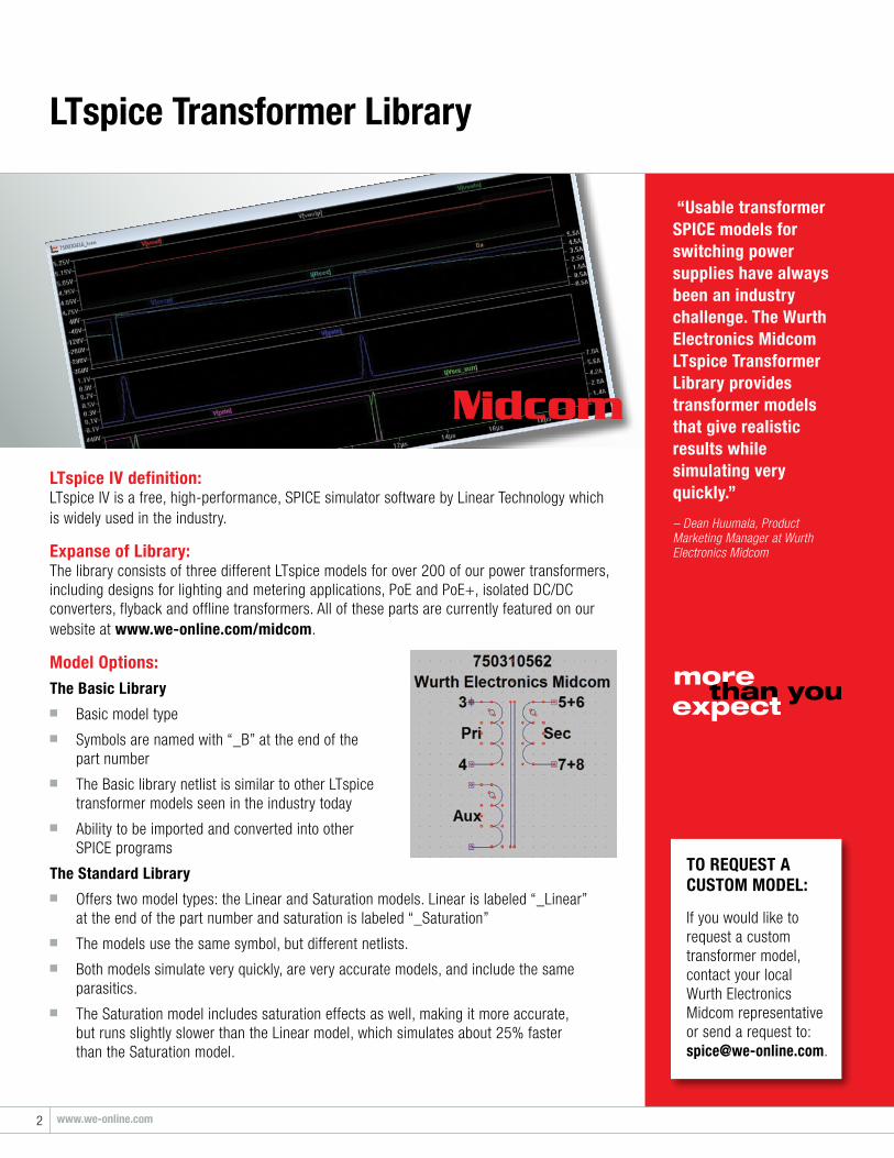
LTspice IV definition:LTspice IV is a free, high-performance, SPICE simulator software by Linear Technology which is widely used in the industry.
Expanse of Library:The library consists of three different LTspice models for over 200 of our power transformers, including designs for lighting and metering applications, PoE and PoE+, isolated DC/DC converters, flyback and offline transformers. All of these parts are currently featured on our website at www.we-online.com/midcom.
Model Options:The Basic Libraryn Basic model typen Symbols are named with “_B” at the end of the part numbern The Basic library netlist is similar to other LTspice transformer models seen in the industry todayn Ability to be imported and converted into other SPICE programs
The Standard Libraryn Offers two model types: the Linear and Saturation models. Linear is labeled “_Linear” at the end of the part number and saturation is labeled “_Saturation”n The models use the same symbol, but different netlists. n Both models simulate very quickly, are very accurate models, and include the same parasitics. n The Saturation model includes saturation effects as well, making it more accurate, but runs slightly slower than the Linear model, which simulates about 25% faster than the Saturation model.
“Usable transformer SPICE models for switching power supplies have always been an industry challenge. The Wurth Electronics Midcom LTspice Transformer Library provides transformer models that give realistic results while simulating very quickly.”
– Dean Huumala, Product Marketing Manager at Wurth Electronics Midcom
TO REQUEST A CUSTOM MODEL:
If you would like to request a custom transformer model, contact your local Wurth Electronics Midcom representative or send a request to: [email protected].
2
LTspice Transformer Library ...............................................................................................................................................................2
Lighting Reference Designs Table ................................................................................................................................................ 4-7
Eagle Library ...............................................................................................................................................................................................8
Speedy Design Service ...........................................................................................................................................................................9
Introduction ...............................................................................................................................................................................................10
LED Lighting and EMI ............................................................................................................................................................................11
Safety
Functional, Basic and Reinforced Insulation .......................................................12
Definitions .......................................................................................................12
Standards Applicable to LED Lighting (UL8750 • IEC60950-1 • UL1310 • EN61347-2-13) ........................................13
Switch Mode Power Supply Topologies Compared .............. 14-16
Topology Selection Flowchart ...............................................................17
Lighting Reference Designs ............................................................. 18-51
Dual Coil: Common Mode Choke .........................................................52
WE-TFC: Common Mode Choke ...........................................................53
Content
3
www.we-online.com
Lighting Reference Designs Table
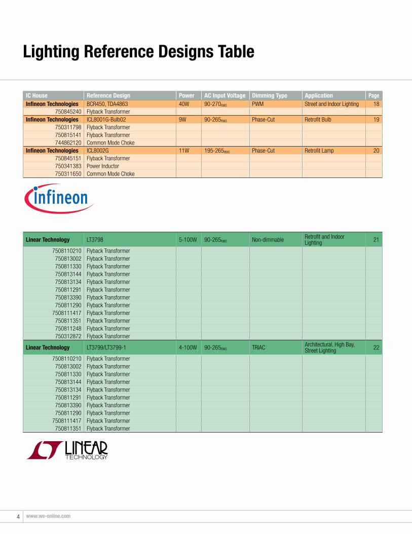
IC House Reference Design Power AC Input Voltage Dimming Type Application PageInfineon Technologies BCR450, TDA4863 40W 90-270RMS PWM Street and Indoor Lighting 18
750845240 Flyback TransformerInfineon Technologies ICL8001G-Bulb02 9W 90-265RMS Phase-Cut Retrofit Bulb 19
750311798 Flyback Transformer750815141 Flyback Transformer744862120 Common Mode Choke
Infineon Technologies ICL8002G 11W 195-265RMS Phase-Cut Retrofit Lamp 20750845151 Flyback Transformer750341383 Power Inductor750311650 Common Mode Choke
Linear Technology LT3798 5-100W 90-265RMS Non-dimmable Retrofit and Indoor Lighting 21
7508110210 Flyback Transformer750813002 Flyback Transformer750811330 Flyback Transformer750813144 Flyback Transformer750813134 Flyback Transformer750811291 Flyback Transformer750813390 Flyback Transformer750811290 Flyback Transformer
7508111417 Flyback Transformer750811351 Flyback Transformer750811248 Flyback Transformer750312872 Flyback Transformer
Linear Technology LT3799/LT3799-1 4-100W 90-265RMS TRIAC Architectural, High Bay, Street Lighting 22
7508110210 Flyback Transformer750813002 Flyback Transformer750811330 Flyback Transformer750813144 Flyback Transformer750813134 Flyback Transformer750811291 Flyback Transformer750813390 Flyback Transformer750811290 Flyback Transformer
7508111417 Flyback Transformer750811351 Flyback Transformer
4
5
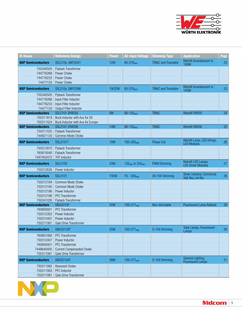
IC House Reference Design Power AC Input Voltage Dimming Type Application Page
NXP Semiconductors SSL210x, UM10341 12W 85-276RMS TRIAC and Transistor Retrofit Incandescent to 100W 23
750340505 Flyback Transformer744776268 Power Choke744776233 Power Choke74477120 Power Choke
NXP Semiconductors SSL210x, UM10386 19/22W 85-276RMS TRIAC and Transistor Retrofit Incandescent to 100W 23
750340505 Flyback Transformer744776268 Input Filter Inductor744776233 Input Filter Inductor74477120 Output Filter Inductor
NXP Semiconductors SSL2101 (PAR30) 9W 90-135RMS TRIAC Retrofit PAR30 24750311819 Buck Inductor with Aux for US750311524 Buck Inductor with Aux for Europe
NXP Semiconductors SSL2101 (PAR38) 14W 90-135RMS TRIAC Retrofit PAR38 25750311525 Flyback Transformer744821120 Common Mode Choke
NXP Semiconductors SSL2101T 10W 185-265RMS Phase-Cut Retrofit Lamp, LED Strings, LED Modules 26
750312870 Flyback Transformer760874040 Flyback Transformer
7447452472 THT Inductor
NXP Semiconductors SSL2109 23W 120RMS or 230RMS PWM Dimming Retrofit LED Lamps, LED Driver Modules 27
750312626 Power Inductor
NXP Semiconductors SSL4101 150W 70 - 305RMS 0V-10V Dimming Street, Industrial, Commercial, High Bay, Low Bay 28
750312184 Common Mode Choke750312185 Common Mode Choke750312186 Power Inductor750312188 PFC Transformer750341026 Flyback Transformer
NXP Semiconductors UBA2015P 35W 100-277RMS Non-dimmable Fluorescent Lamp Ballasts 29760800001 PFC Transformer750312352 Power Inductor750312407 Power Inductor750311081 Gate Drive Transformer
NXP Semiconductors UBA2015AT 35W 100-277RMS 0-10V Dimming Tube Lamps, Fluorescent Lamps 30
760801080 PFC Transformer750312407 Power Inductor760800001 PFC Transformer
7448640405 Current Compensated Choke750311081 Gate Drive Transformer
NXP Semiconductors UBA2016AT 28W 100-277RMS 0-10V Dimming General Lighting, Fluorescent Lamps 31
750311082 Resonant Choke750311083 PFC Inductor 750311081 Gate Drive Transformer
www.we-online.com
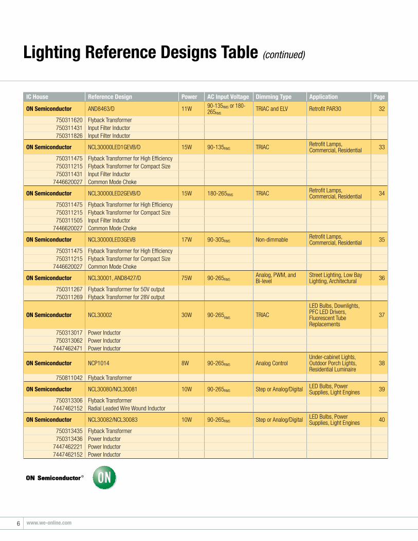
Lighting Reference Designs Table (continued)
IC House Reference Design Power AC Input Voltage Dimming Type Application Page
ON Semiconductor AND8463/D 11W 90-135RMS or 180-265RMS
TRIAC and ELV Retrofit PAR30 32
750311620 Flyback Transformer750311431 Input Filter Inductor750311826 Input Filter Inductor
ON Semiconductor NCL30000LED1GEVB/D 15W 90-135RMS TRIAC Retrofit Lamps, Commercial, Residential 33
750311475 Flyback Transformer for High Efficiency750311215 Flyback Transformer for Compact Size750311431 Input Filter Inductor
7446620027 Common Mode Choke
ON Semiconductor NCL30000LED2GEVB/D 15W 180-265RMS TRIAC Retrofit Lamps, Commercial, Residential 34
750311475 Flyback Transformer for High Efficiency750311215 Flyback Transformer for Compact Size750311505 Input Filter Inductor
7446620027 Common Mode Choke
ON Semiconductor NCL30000LED3GEVB 17W 90-305RMS Non-dimmable Retrofit Lamps, Commercial, Residential 35
750311475 Flyback Transformer for High Efficiency750311215 Flyback Transformer for Compact Size
7446620027 Common Mode Choke
ON Semiconductor NCL30001, AND8427/D 75W 90-265RMSAnalog, PWM, and Bi-level
Street Lighting, Low Bay Lighting, Architectural 36
750311267 Flyback Transformer for 50V output750311269 Flyback Transformer for 28V output
ON Semiconductor NCL30002 30W 90-265RMS
TRIAC
LED Bulbs, Downlights, PFC LED Drivers, Fluorescent Tube Replacements
37
750313017 Power Inductor750313062 Power Inductor
7447462471 Power Inductor
ON Semiconductor NCP1014 8W 90-265RMS Analog ControlUnder-cabinet Lights, Outdoor Porch Lights, Residential Luminaire
38
750811042 Flyback Transformer
ON Semiconductor NCL30080/NCL30081 10W 90-265RMS Step or Analog/Digital LED Bulbs, Power Supplies, Light Engines 39
750313306 Flyback Transformer7447462152 Radial Leaded Wire Wound Inductor
ON Semiconductor NCL30082/NCL30083 10W 90-265RMS Step or Analog/Digital LED Bulbs, Power Supplies, Light Engines 40
750313435 Flyback Transformer750313436 Power Inductor
7447462221 Power Inductor7447462152 Power Inductor
6
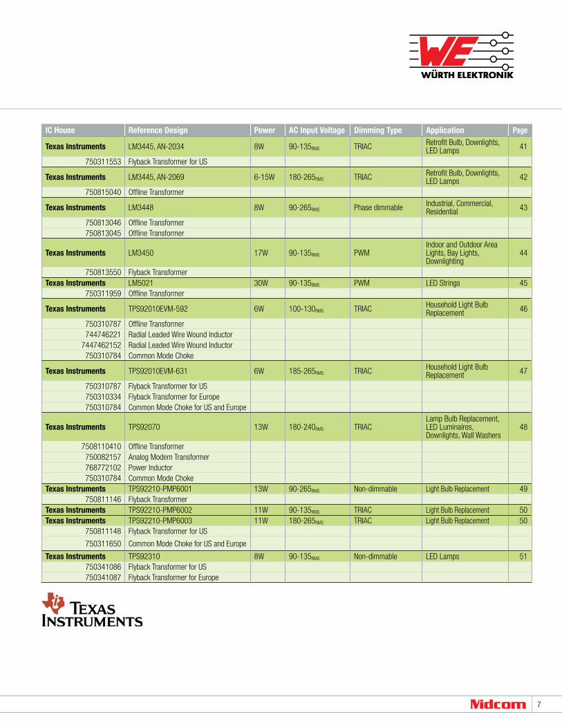
7
IC House Reference Design Power AC Input Voltage Dimming Type Application Page
Texas Instruments LM3445, AN-2034 8W 90-135RMS TRIAC Retrofit Bulb, Downlights,LED Lamps 41
750311553 Flyback Transformer for US
Texas Instruments LM3445, AN-2069 6-15W 180-265RMS TRIAC Retrofit Bulb, Downlights,LED Lamps 42
750815040 Offline Transformer
Texas Instruments LM3448 8W 90-265RMS Phase dimmable Industrial, Commercial, Residential 43
750813046 Offline Transformer750813045 Offline Transformer
Texas Instruments LM3450 17W 90-135RMS PWMIndoor and Outdoor Area Lights, Bay Lights, Downlighting
44
750813550 Flyback TransformerTexas Instruments LM5021 30W 90-135RMS PWM LED Strings 45
750311959 Offline Transformer
Texas Instruments TPS92010EVM-592 6W 100-130RMS TRIAC Household Light Bulb Replacement 46
750310787 Offline Transformer744746221 Radial Leaded Wire Wound Inductor
7447462152 Radial Leaded Wire Wound Inductor750310784 Common Mode Choke
Texas Instruments TPS92010EVM-631 6W 185-265RMS TRIAC Household Light Bulb Replacement 47
750310787 Flyback Transformer for US750310334 Flyback Transformer for Europe750310784 Common Mode Choke for US and Europe
Texas Instruments TPS92070 13W 180-240RMS TRIACLamp Bulb Replacement, LED Luminaires, Downlights, Wall Washers
48
7508110410 Offline Transformer750082157 Analog Modem Transformer768772102 Power Inductor750310784 Common Mode Choke
Texas Instruments TPS92210-PMP6001 13W 90-265RMS Non-dimmable Light Bulb Replacement 49750811146 Flyback Transformer
Texas Instruments TPS92210-PMP6002 11W 90-135RMS TRIAC Light Bulb Replacement 50Texas Instruments TPS92210-PMP6003 11W 180-265RMS TRIAC Light Bulb Replacement 50
750811148 Flyback Transformer for US
750311650 Common Mode Choke for US and Europe
Texas Instruments TPS92310 8W 90-135RMS Non-dimmable LED Lamps 51750341086 Flyback Transformer for US750341087 Flyback Transformer for Europe
www.we-online.com
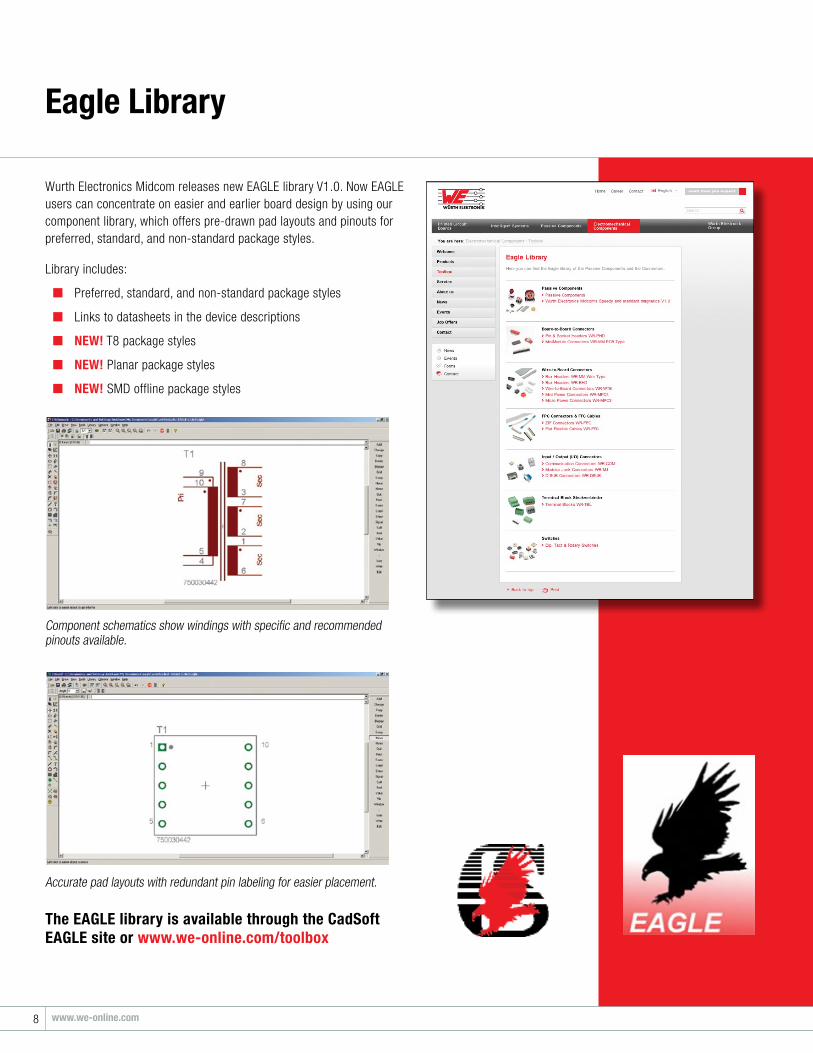
Wurth Electronics Midcom releases new EAGLE library V1.0. Now EAGLE users can concentrate on easier and earlier board design by using our component library, which offers pre-drawn pad layouts and pinouts for preferred, standard, and non-standard package styles.
Library includes:
n Preferred, standard, and non-standard package styles
n Links to datasheets in the device descriptions
n NEW! T8 package styles
n NEW! Planar package styles
n NEW! SMD offline package styles
Component schematics show windings with specific and recommended pinouts available.
Accurate pad layouts with redundant pin labeling for easier placement.
The EAGLE library is available through the CadSoft EAGLE site or www.we-online.com/toolbox
Eagle Library
8

Speedy Design Servicefor Customized Power & Telecom Transformers
World’s fastest sample service for customized transformers
Complete Speedy Design Form
www.we-online.com/speedy
1
Choose your designated service option2
3 Send to Wurth Electronics Midcom
Email: [email protected] or
Contact: your local Wurth Electronics Midcom salesperson
4 This is what you receive:
Specification Sheet, Test Data, and 5 Customized Pieces What applications are supported?
• Any applications that fit package styles
• Switch Mode Power: - Flyback - Forward - Push-Pull - Coupled Inductors
• Telecom Applications: - xDSL - POTS Splitter Inductors
Selected Service Time Price
Ship next day* $1,200
Ship in 3 days* $900
*Shipped with FedEx Priority
more than you expect
Please complete and e-mail to [email protected] or fax to Wurth Electronics Midcom Inc. +1 605 886 4486. Only include the specifications you require.
Company Information
Company
Department
Name
Street
City / State
Postal Code Country
Phone Fax
Application If product safety is an issue, please contact us immediately for technical consultation. Our products are not designed for aviation, medical, automotive or life supporting devices. Such applications require our written approval prior to use.
IC Manufacturer Target Price
IC Number/Name Estimated Annual Usage
Application/Project Name Start of Production
Specification Complete only those specifications of interest and number in order of priority.
Agency Requirements
General Specifications Value Priority *
Primary Inductance (µH)
Current in Primary (A)
Turns Ratio
Leakage Inductance (µH)
Telecom Parts Value Priority *
Frequency Response (dB)
Return Loss (dB)
Total Harmonic Distortion (dB)
Longitudinal Balance (dB)
Line Impedance (Ω)
Load Impedance (Ω)
Power Parts Value Priority *
Topology
Total Output Power (W)
Input Voltage Range (V)
Operating Frequency (kHz)
Max. & Min. Duty Cycle
VAUX (V) indicate PRI or SEC
IAUX (A)
VSEC1 with VDIODE (V)
ISEC1 (A)
VSEC2 with VDIODE (V)
ISEC2 (A)
Temperature Range:
Note: Wurth Electronics Midcom Inc. will design to meet the specifications as closely as pos-sible with emphasis given to those parameters with priority. Samples will ship with necessary deviations reported along with the test data.
Service Ordered ship next day
ship 3 days
Package Style: EP5 EP7 EP10 EP13 EPX7 EPX9 ER9.5 ER11.5 ER14.5 EFD15 EFD20 EFD25 EF12.6 EE13 EE16 EF16 EF20 EF25 ER28
Regulatory Agencies: IEC61558 IEC60950 UL1310 Other Insulation Requirements: Functional Functional
Basic Basic Supplementary Supplementary Reinforced Reinforced
Dielectric Withstand Voltage Working Voltage
Payment Type Purchase Order (#__________________________)
Credit Card (Visa, MasterCard, American Express)
* Priority: Please prioritize the most important specifications with numbers (e.g. 1, 2, 3)
Speedy Design ServiceOrder Form
9
www.we-online.com
Introduction
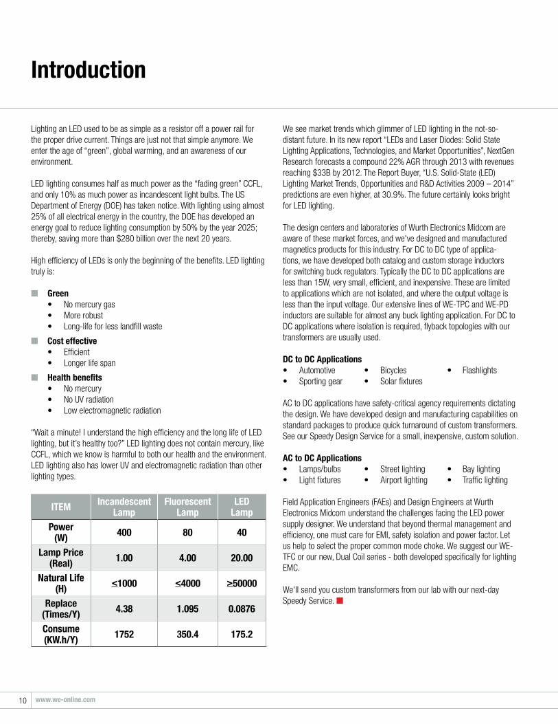
Lighting an LED used to be as simple as a resistor off a power rail for the proper drive current. Things are just not that simple anymore. We enter the age of “green”, global warming, and an awareness of our environment.
LED lighting consumes half as much power as the “fading green” CCFL, and only 10% as much power as incandescent light bulbs. The US Department of Energy (DOE) has taken notice. With lighting using almost 25% of all electrical energy in the country, the DOE has developed an energy goal to reduce lighting consumption by 50% by the year 2025; thereby, saving more than $280 billion over the next 20 years.
High efficiency of LEDs is only the beginning of the benefits. LED lighting truly is:
n Green • No mercury gas • More robust • Long-life for less landfill waste
n Cost effective • Efficient • Longer life span
n Health benefits • No mercury • No UV radiation • Low electromagnetic radiation
“Wait a minute! I understand the high efficiency and the long life of LED lighting, but it’s healthy too?” LED lighting does not contain mercury, like CCFL, which we know is harmful to both our health and the environment. LED lighting also has lower UV and electromagnetic radiation than other lighting types.
ITEM Incandescent Lamp
FluorescentLamp
LEDLamp
Power(W) 400 80 40
Lamp Price(Real) 1.00 4.00 20.00
Natural Life(H)
<1000 <4000 >50000
Replace(Times/Y) 4.38 1.095 0.0876
Consume(KW.h/Y) 1752 350.4 175.2
We see market trends which glimmer of LED lighting in the not-so-distant future. In its new report “LEDs and Laser Diodes: Solid State Lighting Applications, Technologies, and Market Opportunities”, NextGen Research forecasts a compound 22% AGR through 2013 with revenues reaching $33B by 2012. The Report Buyer, “U.S. Solid-State (LED) Lighting Market Trends, Opportunities and R&D Activities 2009 – 2014” predictions are even higher, at 30.9%. The future certainly looks bright for LED lighting.
The design centers and laboratories of Wurth Electronics Midcom are aware of these market forces, and we've designed and manufactured magnetics products for this industry. For DC to DC type of applica-tions, we have developed both catalog and custom storage inductors for switching buck regulators. Typically the DC to DC applications are less than 15W, very small, efficient, and inexpensive. These are limited to applications which are not isolated, and where the output voltage is less than the input voltage. Our extensive lines of WE-TPC and WE-PD inductors are suitable for almost any buck lighting application. For DC to DC applications where isolation is required, flyback topologies with our transformers are usually used.
DC to DC Applications• Automotive • Bicycles • Flashlights• Sporting gear • Solar fixtures
AC to DC applications have safety-critical agency requirements dictating the design. We have developed design and manufacturing capabilities on standard packages to produce quick turnaround of custom transformers. See our Speedy Design Service for a small, inexpensive, custom solution.
AC to DC Applications• Lamps/bulbs • Street lighting • Bay lighting• Light fixtures • Airport lighting • Traffic lighting
Field Application Engineers (FAEs) and Design Engineers at Wurth Electronics Midcom understand the challenges facing the LED power supply designer. We understand that beyond thermal management and efficiency, one must care for EMI, safety isolation and power factor. Let us help to select the proper common mode choke. We suggest our WE-TFC or our new, Dual Coil series - both developed specifically for lighting EMC.
We'll send you custom transformers from our lab with our next-day Speedy Service. n
10
11
LED Lighting and EMI
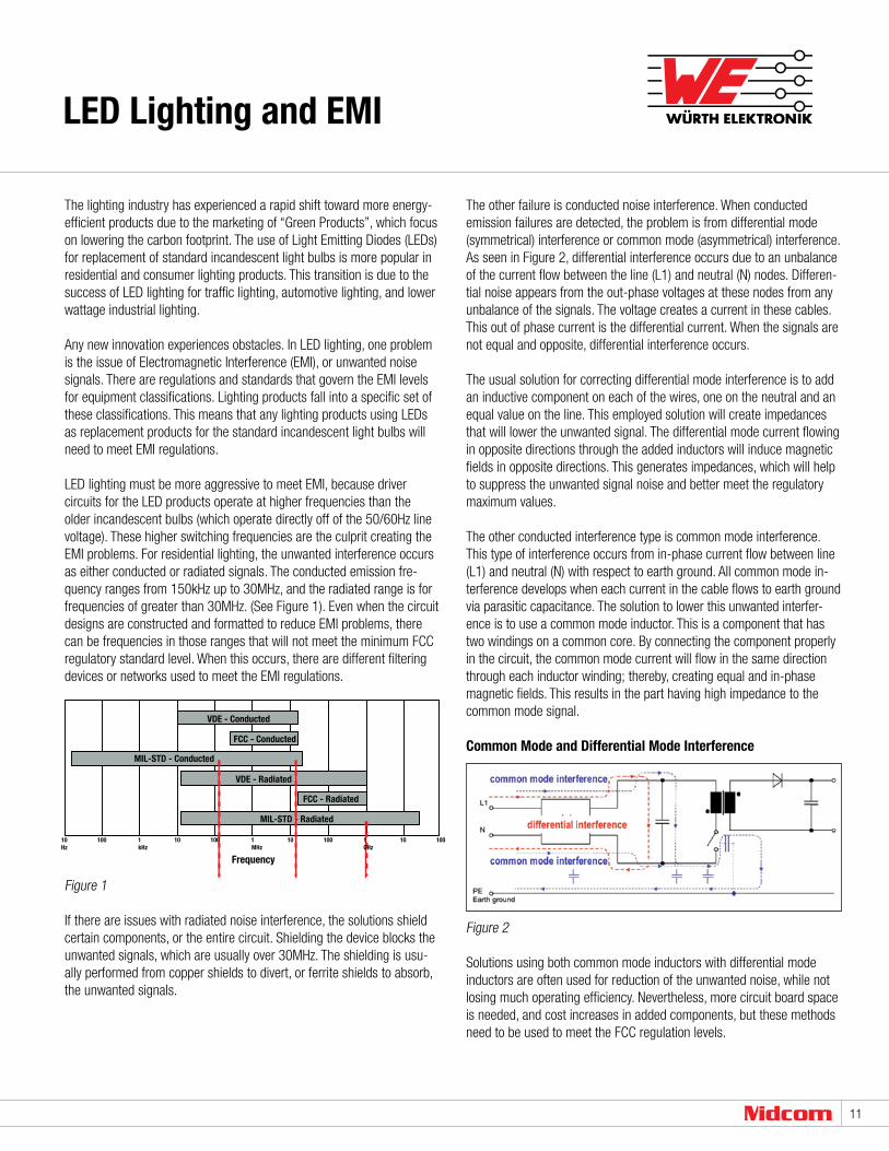
The lighting industry has experienced a rapid shift toward more energy- efficient products due to the marketing of “Green Products”, which focus on lowering the carbon footprint. The use of Light Emitting Diodes (LEDs) for replacement of standard incandescent light bulbs is more popular in residential and consumer lighting products. This transition is due to the success of LED lighting for traffic lighting, automotive lighting, and lower wattage industrial lighting. Any new innovation experiences obstacles. In LED lighting, one problem is the issue of Electromagnetic Interference (EMI), or unwanted noise signals. There are regulations and standards that govern the EMI levels for equipment classifications. Lighting products fall into a specific set of these classifications. This means that any lighting products using LEDs as replacement products for the standard incandescent light bulbs will need to meet EMI regulations. LED lighting must be more aggressive to meet EMI, because driver circuits for the LED products operate at higher frequencies than the older incandescent bulbs (which operate directly off of the 50/60Hz line voltage). These higher switching frequencies are the culprit creating the EMI problems. For residential lighting, the unwanted interference occurs as either conducted or radiated signals. The conducted emission fre-quency ranges from 150kHz up to 30MHz, and the radiated range is for frequencies of greater than 30MHz. (See Figure 1). Even when the circuit designs are constructed and formatted to reduce EMI problems, there can be frequencies in those ranges that will not meet the minimum FCC regulatory standard level. When this occurs, there are different filtering devices or networks used to meet the EMI regulations.
Figure 1
If there are issues with radiated noise interference, the solutions shield certain components, or the entire circuit. Shielding the device blocks the unwanted signals, which are usually over 30MHz. The shielding is usu-ally performed from copper shields to divert, or ferrite shields to absorb, the unwanted signals.
The other failure is conducted noise interference. When conducted emission failures are detected, the problem is from differential mode (symmetrical) interference or common mode (asymmetrical) interference. As seen in Figure 2, differential interference occurs due to an unbalance of the current flow between the line (L1) and neutral (N) nodes. Differen-tial noise appears from the out-phase voltages at these nodes from any unbalance of the signals. The voltage creates a current in these cables. This out of phase current is the differential current. When the signals are not equal and opposite, differential interference occurs.
The usual solution for correcting differential mode interference is to add an inductive component on each of the wires, one on the neutral and an equal value on the line. This employed solution will create impedances that will lower the unwanted signal. The differential mode current flowing in opposite directions through the added inductors will induce magnetic fields in opposite directions. This generates impedances, which will help to suppress the unwanted signal noise and better meet the regulatory maximum values.
The other conducted interference type is common mode interference. This type of interference occurs from in-phase current flow between line (L1) and neutral (N) with respect to earth ground. All common mode in-terference develops when each current in the cable flows to earth ground via parasitic capacitance. The solution to lower this unwanted interfer-ence is to use a common mode inductor. This is a component that has two windings on a common core. By connecting the component properly in the circuit, the common mode current will flow in the same direction through each inductor winding; thereby, creating equal and in-phase magnetic fields. This results in the part having high impedance to the common mode signal. Common Mode and Differential Mode Interference
Figure 2
Solutions using both common mode inductors with differential mode inductors are often used for reduction of the unwanted noise, while not losing much operating efficiency. Nevertheless, more circuit board space is needed, and cost increases in added components, but these methods need to be used to meet the FCC regulation levels.
!
VDE - Conducted
FCC - Conducted
MIL-STD - Conducted
VDE - Radiated
FCC - Radiated
MIL-STD - Radiated
Frequency
10 100 1 10 100 1 10 100 1 10 100Hz kHz MHz GHz
!
www.we-online.com12
Safety
Functional, Basic, and Reinforced Insulation
The affect of insulation requirements is significant enough to change the form factor, performance, cost, and of course, reliability of the transformer. In general terms, functional insulation is the easiest insulation to achieve. It allows for magnet wire to be in contact with other magnet wire and has no creepage or clearance requirements. The insulation strength is tested by a simple dielectric (hipot) test.
Both basic and reinforced insulation are common to parts subject to offline voltages (85-265V
AC). The primary difference between these two
types of insulation and functional insulation is that basic and reinforced require physical separation between windings, solder joints, and cores. These distances are known as creepage and clearance. There are a several methods to achieve distance requirements; multi-section bobbins, encapsulation, margin tape, and extruded insulated wire are the most common. You can imagine certain drawbacks to the special insulation: increased size, reduced coupling, lower efficiency, decreased manufactur-ing capacity, and limited pin configuration options.
The distance requirements and lead isolation are set by specific stan-dards. Reinforced insulation is typically twice that of basic insulation. In some cases, special materials can be used to reduce the distance requirements. In other cases, lead-in routing rules can cause signifi-cant manual production processes, especially when pin configuration is fixed.
Functional Basic/Reinforced
Size + -Pinout flexibility + -
Efficiency + -Coupling + -
Manufacturing capacity/leadtime + -Cost + -
Safety - +Dielectric withstand - +
Definitions
Basic Insulation
Insulation applies to hazardous live parts to provide basic protection against electric shock.
Double Insulation
Insulation comprising both basic insulation and supplementary insulation.
Functional Insulation
Insulation that is necessary only for the func-tioning of the equipment
Reinforced Insulation
Single insulation system that provides a degree of protection against electric shock equivalent to double insulation
Creepage Distance
Shortest distance through air along the surface of an insulation material between two conductive parts
Clearance Distance
Shortest distance in air between two conduc-tive parts
Working Voltage
Highest voltage to which the insulation or the component under consideration is, or can be, subjected when the equipment is operating under conditions of normal use
13
Standards Applicable to LED Lighting
n UL8750
• LED Components - Specifies the safety requirements for LED light sources and the components
i. Spacing requirement of 0.8mm
ii. Dielectric requirements
1. 1000VAC
plus twice the AC (RMS) voltage between:
a. The primary circuit and accessible dead parts; and
b. The primary and secondary circuit or circuits
2. 500V between a secondary circuit operating at 70V peak or less and accessible dead metal parts
n IEC60950-1
• Information Technology Equipment – Specifies the safety requirements for electronic hardware
i. Spacing requirements of 8mm for reinforced 400V
ii. Dielectric requirement: 1500- 4500VAC
n UL1310
• Class 2 Power Units - Specifies the safety requirements for Class 2 power supplies
i. Spacing requirement same as UL8750
ii. Dielectric requirements
1. 1000VAC
plus twice the maximum rated voltage between:
a. The primary circuit and accessible dead metal parts; and
b. The primary and secondary circuit or circuits
2. 1000VAC
plus two times the sum of secondary voltages between secondary windings for units described in 28.3 or 30.2.3
3. 500VAC
between a secondary circuit and dead metal parts
n EN61347-2-13
• Lamp Control Gear – Specifies safety requirement for DC or AC supplied electronic control gear for LED modules
i. Spacing requirements of 3-6mm
ii. Dielectric requirement
1. Basic insulation: 2U+1000V
2. Supplementary insulation: 2U+1750V
3. Reinforced insulation: 4U+2750V
www.we-online.com14
Switch Mode Power SupplyTopologies Compared
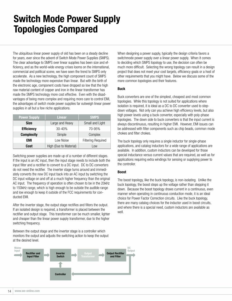
The ubiquitous linear power supply of old has been on a steady decline for years, ever since the advent of Switch Mode Power Supplies (SMPS). The clear advantage to SMPS over linear supplies has been size and ef-ficiency, and as the world-wide energy crises looms on the international, commercial and political scene, we have seen the trend to SMPS only accelerate. As a new technology, the high component count of SMPS made the technology more expensive than linear. But with the birth of the electronic age, component costs have dropped so low that the high raw material content of copper and iron in the linear transformer has made the SMPS technology more cost effective. Even with the disad-vantages of being more complex and requiring more care to control EMI, the advantages of switch mode power supplies far outweigh linear power supplies in all but a few niche applications.
Power Supply Linear SMPS
Size Large and Heavy Small and Light
Efficiency 30-40% 70-95%
Complexity Simple Complex
EMI Low Noise Filtering Required
Cost High (Due to Material) Low
Switching power supplies are made up of a number of different stages. If the input is an AC input, then the input stage needs to include both the input filter and a rectifier to convert to a DC input. DC to DC converters do not need the rectifier. The inverter stage turns around and immedi-ately converts the now DC input back into an AC input by switching the DC input voltage on and off at a much higher frequency than the original AC input. The frequency of operation is often chosen to be in the 20kHz to 150kHz range, which is high enough to be outside the audible range and low enough to keep it outside of the FCC requirements for con-ducted EMI.
After the inverter stage, the output stage rectifies and filters the output. If an isolated design is required, a transformer is placed between the rectifier and output stage. This transformer can be much smaller, lighter and cheaper than the linear power supply transformer, due to the higher switching frequency.
Between the output stage and the inverter stage is a controller which monitors the output and adjusts the switching action to keep the output at the desired level.
When designing a power supply, typically the design criteria favors a switchmode power supply over a linear power supply. When it comes to deciding which SMPS topology to use, the decision can often be much more difficult. Selecting the wrong topology can result in a design project that does not meet your cost targets, efficiency goals or a host of other requirements that you might have. Below we discuss some of the more common topologies and their features.
Buck
Buck converters are one of the simplest, cheapest and most common topologies. While this topology is not suited for applications where isolation is required, it is ideal as a DC to DC converter used to step-down voltages. Not only can you achieve high efficiency levels, but also high power levels using a buck converter, especially with poly-phase topologies. The down side to buck converters is that the input current is always discontinuous, resulting in higher EMI. However, EMI issues can be addressed with filter components such as chip beads, common mode chokes and filter chokes.
The buck topology only requires a single inductor for single-phase applications, and catalog inductors for a wide range of applications are available. In addition, custom inductors can be developed for those special inductance versus current values that are required, as well as for applications requiring extra windings for sensing or supplying power to the controller.
Boost
The boost topology, like the buck topology, is non-isolating. Unlike the buck topology, the boost steps up the voltage rather than stepping it down. Because the boost topology draws current in a continuous, even manner when operating in continuous conduction mode, it is an ideal choice for Power Factor Correction circuits. Like the buck topology, there are many catalog choices for the inductor used in boost circuits, and where there is a special need, custom inductors are available as well.
Rectier andInput Filter
InverterSwitch
Controller
Output Rectierand Filter
OutputTransformer
MainsInput
DCOutput
15
Buck-Boost
The buck-boost topology can either step the voltage up or down. This topology is particularly useful in battery powered applications, where the input voltage varies over time but has the disadvantage of inverting the output voltage. Another disadvantage to the buck-boost topology is that the switch does not have a ground, which complicates the drive circuit. Using only a single inductor like the buck and the boost topologies, the buck-boost inductor and EMI components are readily available.
SEPIC/Ćuk
The SEPIC and Ćuk topologies both use capacitors for energy storage in addition to two inductors. The two inductors can be either separate inductors or a single component in the form of a coupled inductor. Both topologies are similar to the buck-boost topology in that they can step-up or step-down the input voltage, making them ideal for battery applications. The SEPIC has the additional advantage over both the Ćuk and the buck-boost in that its output is non-inverting. An advantage to the SEPIC/Ćuk topologies is that the capacitor can offer some limited isolation. Catalog coupled inductors are available for the SEPIC and Ćuk topologies, and custom inductors are readily available for special needs.
Flyback
The flyback topology is essentially the buck-boost topology that is isolated by using a transformer as the storage inductor. The transformer not only provides isolation, but by varying the turns ratio, the output volt-age can be adjusted. Since a transformer is used, multiple outputs are possible. The flyback is the simplest and most common of the isolated topologies for low-power applications. While they are well suited for high-output voltages, the peak currents are very high, and the topology does not lend itself well to output current above 10A. One advantage of the flyback topology over the other isolated topologies is that many of them require a separate storage inductor. Since the flyback transformer is in reality the storage inductor, no separate inductor is needed. This, coupled with the fact that the rest of the circuitry is simple, makes the flyback topology a cost effective and popular topology.
Forward
The forward converter is really just a transformer isolated buck converter. Like the flyback topology, the forward converter is best suited for lower power applications. While efficiency is comparable to the flyback, it does have the disadvantage of having an extra inductor on the output and is not well suited for high voltage outputs. The forward converter does have the advantage over the flyback converter when high output currents are required. Since the output current is non-pulsating, it is well suited for applications where the current is in excess of 15A.
Push-Pull
The push-pull topology is essentially a forward converter with two pri-mary windings used to create a dual drive winding. This utilizes the core of the transformer much more efficiently than the flyback or the forward converters. On the other hand, only half the copper is being used at a time, thereby increasing the copper losses significantly in a similar sized transformer. For similar power levels, the push-pull converter will have smaller filters compared to the forward converter. However the advan-tage that push-pull converters have over flyback and forward converters is that they can be scaled up to higher powers. Switching control can be difficult with push-pull converters, because care has to be taken not to turn on both switches at the same time. Doing so will cause the equal and opposite flux in the transformer, resulting in a low impedance and a very large shoot-through current through the switch, potentially destroy-ing it. The other disadvantage to the push-pull topology is that the switch stresses are very high (2∙V
IN), which makes the topology undesir-
able for 250VAC
and PFC applications.
Half-Bridge
The half-bridge topology, like push-pull topologies, can be scaled up well to higher power levels and is based on the forward converter topology. This topology also has the same issue of the shoot-through current, if both switches are on at the same time. In order to control this, there needs to be a dead-time between the on-time of each switch. This limits the duty-cycle to about 45%. Beneficially, the half-bridge topology switching stresses are equal to the input voltage and make it much more suited to 250V
AC and PFC applications. On the flip side, the output
currents are much higher than the push-pull topology, thereby making it less suited for high current outputs.
Resonant LLC
The resonant LLC topology is a half-bridge topology that uses a resonant technique to reduce the switching losses due to zero voltage switching, even in no-load conditions. This topology scales up well to high power levels and has very low losses in devices that are on at all times. This topology is not as well suited for stand-by mode power supplies, as the resonant tank circuit needs to be energized continuously. The resonant LLC also has the advantage over both push-pull and half-bridge topolo-gies of being suitable for a wide range of input voltages. The down side to the resonant LLC topology is its complexity and cost.
www.we-online.com16
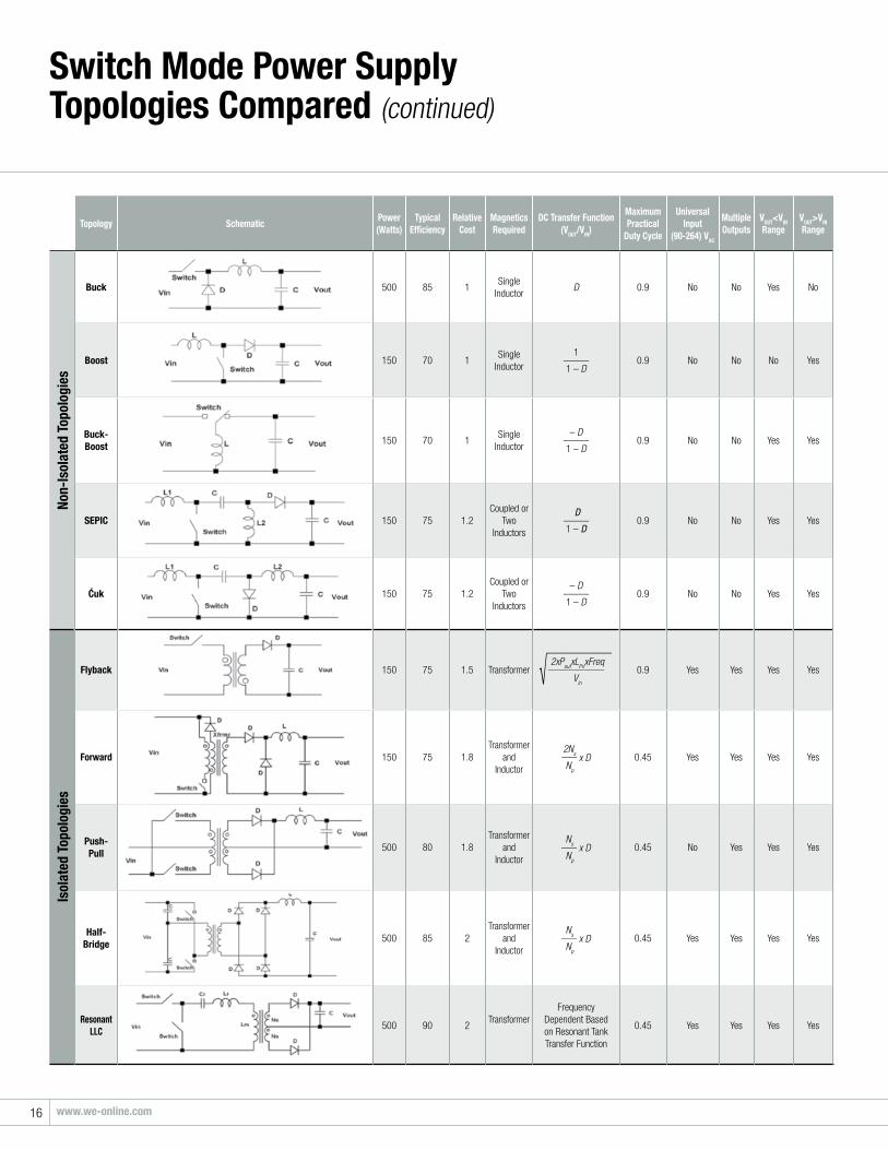
Switch Mode Power SupplyTopologies Compared (continued)
Pow-er
Sup-ply
Topology SchematicPower(Watts)
TypicalEfficiency
RelativeCost
MagneticsRequired
DC Transfer Function(VOUT/VIN)
MaximumPractical
Duty Cycle
Universal Input
(90-264) VAC
MultipleOutputs
VOUT<VIN
RangeVOUT>VIN
Range
Buck 500 85 1Single
InductorD 0.9 No No Yes No
Boost 150 70 1Single
Inductor
1_____1 – D
0.9 No No No Yes
Buck-Boost
150 70 1Single
Inductor
– D_____1 – D
0.9 No No Yes Yes
SEPIC 150 75 1.2Coupled or
TwoInductors
D_____1 – D
0.9 No No Yes Yes
Ćuk 150 75 1.2Coupled or
TwoInductors
– D_____1 – D
0.9 No No Yes Yes
Flyback 150 75 1.5 Transformer 2xPoutxLPrixFreq ___________
Vin
0.9 Yes Yes Yes Yes
Forward 150 75 1.8Transformer
andInductor
2Ns ___ x D Np
0.45 Yes Yes Yes Yes
Push-Pull
500 80 1.8Transformer
andInductor
Ns ___ x D Np
0.45 No Yes Yes Yes
Half-Bridge
500 85 2Transformer
andInductor
Ns ___ x D Np
0.45 Yes Yes Yes Yes
ResonantLLC
500 90 2Transformer
Frequency Dependent Based on Resonant Tank Transfer Function
0.45 Yes Yes Yes Yes
Isol
ated
Top
olog
ies
Non-
Isol
ated
Top
olog
ies
√__________
17
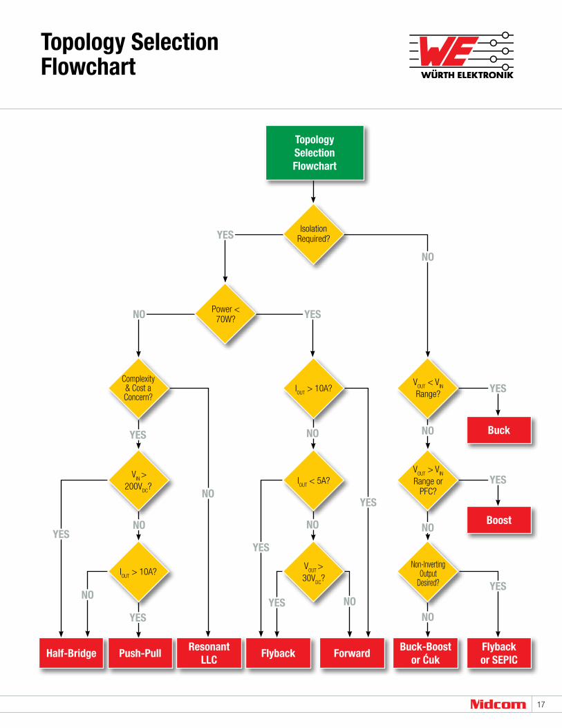
Topology SelectionFlowchart
TopologySelectionFlowchart
YES
Buck
Boost
Flybackor SEPIC
Half-Bridge Push-PullResonant
LLCFlyback Forward
Buck-Boostor Ćuk
YES
YES
YES
YES
YES
YES
YES
YES
YES
YES
NO
NO
NO
NO
NO
NO
NONO
NO
NO NO
IsolationRequired?
Power <70W?
Complexity& Cost aConcern?
IOUT
> 10A?V
OUT < V
IN
Range?
VIN
>200V
DC?
IOUT
< 5A?V
OUT > V
IN
Range orPFC?
IOUT
> 10A?V
OUT >
30VDC
?
Non-InvertingOutput
Desired?
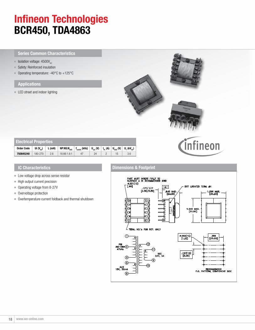
Infineon TechnologiesBCR450, TDA4863
Dimensions & Footprint
Applications
n LED street and indoor lighting
Series Common Characteristics
n Isolation voltage: 4500VAC
n Safety: Reinforced insulation
n Operating temperature: -40°C to +125°C
IC Characteristics
n Low voltage drop across sense resistor
n High output current precision
n Operating voltage from 8-27V
n Overvoltage protection
n Overtemperature current foldback and thermal shutdown
Electrical PropertiesOrder Code Ui (VAC) L (mH) NP:NS:NAUX fswitch (kHz) Uout (V) I01 (A) UAUX (V) UT (kVAC)
750845240 180-270 2.6 18.66:1.6:1 47 24 2 15 3.6
www.we-online.com18
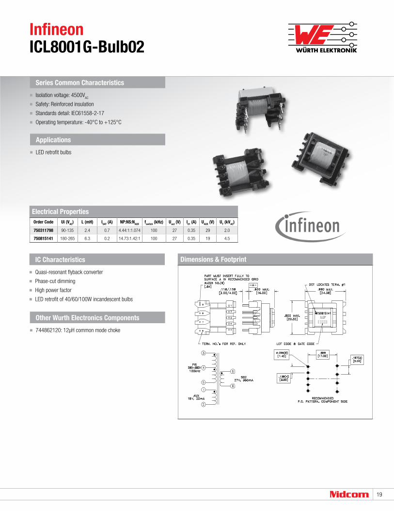
Dimensions & Footprint
InfineonICL8001G-Bulb02
Applications
n LED retrofit bulbs
Series Common Characteristics
n Isolation voltage: 4500VAC
n Safety: Reinforced insulation
n Standards detail: IEC61558-2-17
n Operating temperature: -40°C to +125°C
IC Characteristics
n Quasi-resonant flyback converter
n Phase-cut dimming
n High power factor
n LED retrofit of 40/60/100W incandescent bulbs
Electrical PropertiesOrder Code Ui (VAC) L (mH) ISAT (A) NP:NS:NAUX fswitch (kHz) Uout (V) I01 (A) UAUX (V) UT (kVAC)
750311798 90-135 2.4 0.7 4.44:1:1.074 100 27 0.35 29 2.0
750815141 180-265 6.3 0.2 14.73:1.42:1 100 27 0.35 19 4.5
Other Wurth Electronics Components
n 744862120: 12µH common mode choke
19
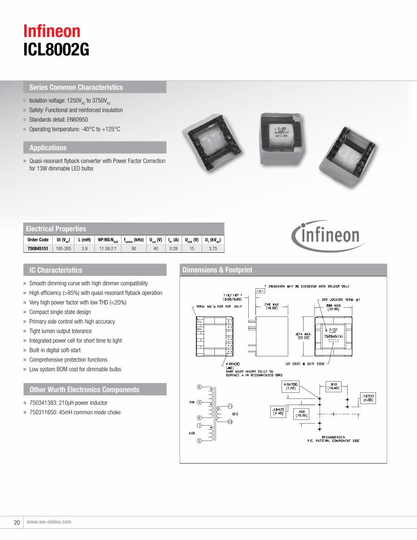
Dimensions & Footprint
Applications
n Quasi-resonant flyback converter with Power Factor Correction for 13W dimmable LED bulbs
Series Common Characteristics
n Isolation voltage: 1250VAC
to 3750VAC
n Safety: Functional and reinforced insulation
n Standards detail: EN60950
n Operating temperature: -40°C to +125°C
InfineonICL8002G
IC Characteristics
n Smooth dimming curve with high dimmer compatibility
n High efficiency (>85%) with quasi-resonant flyback operation
n Very high power factor with low THD (<20%)
n Compact single state design
n Primary side control with high accuracy
n Tight lumen output tolerance
n Integrated power cell for short time to light
n Built-in digital soft-start
n Comprehensive protection functions
n Low system BOM cost for dimmable bulbs
Electrical PropertiesOrder Code Ui (VAC) L (mH) NP:NS:NAUX fswitch (kHz) Uout (V) I01 (A) UAUX (V) UT (kVAC)
750845151 195-265 3.9 11.58:2:1 90 40 0.28 15 3.75
Other Wurth Electronics Components
n 750341383: 210µH power inductor
n 750311650: 45mH common mode choke
www.we-online.com20
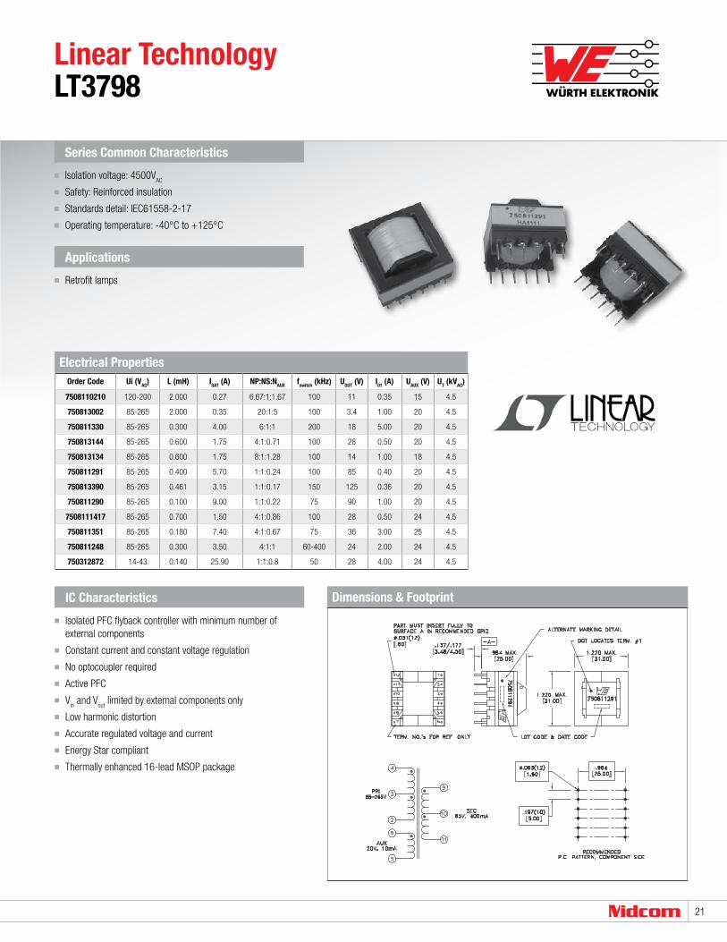
Dimensions & Footprint
Electrical PropertiesOrder Code Ui (VAC) L (mH) ISAT (A) NP:NS:NAUX fswitch (kHz) UOUT (V) I01 (A) UAUX (V) UT (kVAC)
7508110210 120-200 2.000 0.27 6.67:1:1.67 100 11 0.35 15 4.5
750813002 85-265 2.000 0.35 20:1:5 100 3.4 1.00 20 4.5
750811330 85-265 0.300 4.00 6:1:1 200 18 5.00 20 4.5
750813144 85-265 0.600 1.75 4:1:0.71 100 28 0.50 20 4.5
750813134 85-265 0.600 1.75 8:1:1.28 100 14 1.00 18 4.5
750811291 85-265 0.400 5.70 1:1:0.24 100 85 0.40 20 4.5
750813390 85-265 0.461 3.15 1:1:0.17 150 125 0.36 20 4.5
750811290 85-265 0.100 9.00 1:1:0.22 75 90 1.00 20 4.5
7508111417 85-265 0.700 1.50 4:1:0.86 100 28 0.50 24 4.5
750811351 85-265 0.180 7.40 4:1:0.67 75 36 3.00 25 4.5
750811248 85-265 0.300 3.50 4:1:1 60-400 24 2.00 24 4.5
750312872 14-43 0.140 25.90 1:1:0.8 50 28 4.00 24 4.5
Applications
n Retrofit lamps
Series Common Characteristics
n Isolation voltage: 4500VAC
n Safety: Reinforced insulation
n Standards detail: IEC61558-2-17
n Operating temperature: -40°C to +125°C
Linear TechnologyLT3798
IC Characteristics
n Isolated PFC flyback controller with minimum number of external components
n Constant current and constant voltage regulation
n No optocoupler required
n Active PFC
n Vin and V
out limited by external components only
n Low harmonic distortion
n Accurate regulated voltage and current
n Energy Star compliant
n Thermally enhanced 16-lead MSOP package
21
Dimensions & Footprint
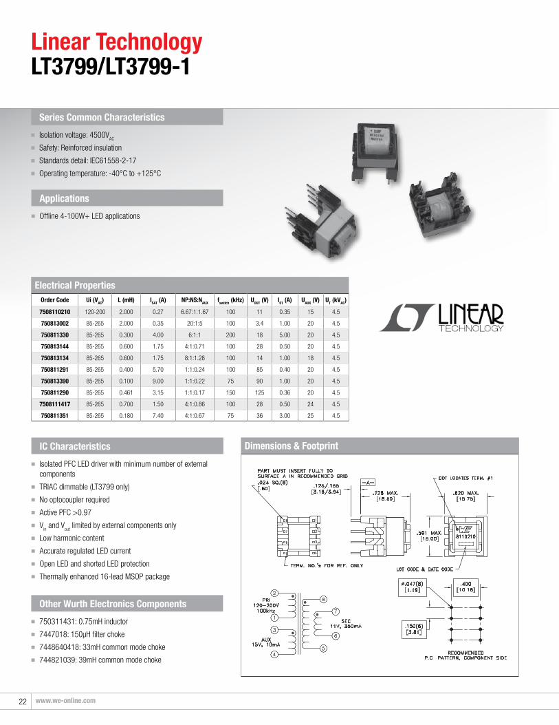
Linear TechnologyLT3799/LT3799-1
Applications
n Offline 4-100W+ LED applications
Series Common Characteristics
n Isolation voltage: 4500VAC
n Safety: Reinforced insulation
n Standards detail: IEC61558-2-17
n Operating temperature: -40°C to +125°C
IC Characteristics
n Isolated PFC LED driver with minimum number of external components
n TRIAC dimmable (LT3799 only)
n No optocoupler required
n Active PFC >0.97
n Vin and V
out limited by external components only
n Low harmonic content
n Accurate regulated LED current
n Open LED and shorted LED protection
n Thermally enhanced 16-lead MSOP package
Electrical PropertiesOrder Code Ui (VAC) L (mH) ISAT (A) NP:NS:NAUX fswitch (kHz) UOUT (V) I01 (A) UAUX (V) UT (kVAC)
7508110210 120-200 2.000 0.27 6.67:1:1.67 100 11 0.35 15 4.5
750813002 85-265 2.000 0.35 20:1:5 100 3.4 1.00 20 4.5
750811330 85-265 0.300 4.00 6:1:1 200 18 5.00 20 4.5
750813144 85-265 0.600 1.75 4:1:0.71 100 28 0.50 20 4.5
750813134 85-265 0.600 1.75 8:1:1.28 100 14 1.00 18 4.5
750811291 85-265 0.400 5.70 1:1:0.24 100 85 0.40 20 4.5
750813390 85-265 0.100 9.00 1:1:0.22 75 90 1.00 20 4.5
750811290 85-265 0.461 3.15 1:1:0.17 150 125 0.36 20 4.5
7508111417 85-265 0.700 1.50 4:1:0.86 100 28 0.50 24 4.5
750811351 85-265 0.180 7.40 4:1:0.67 75 36 3.00 25 4.5
Other Wurth Electronics Components
n 750311431: 0.75mH inductor
n 7447018: 150µH filter choke
n 7448640418: 33mH common mode choke
n 744821039: 39mH common mode choke
www.we-online.com22
Dimensions & Footprint
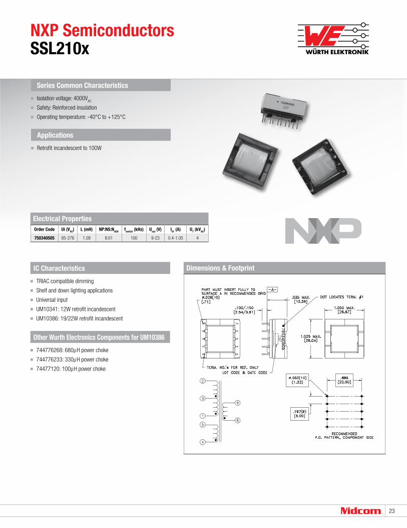
NXP SemiconductorsSSL210x
Applications
n Retrofit incandescent to 100W
Series Common Characteristics
n Isolation voltage: 4000VAC
n Safety: Reinforced insulation
n Operating temperature: -40°C to +125°C
IC Characteristics
n TRIAC compatible dimming
n Shelf and down lighting applications
n Universal input
n UM10341: 12W retrofit incandescent
n UM10386: 19/22W retrofit incandescent
Electrical PropertiesOrder Code Ui (VAC) L (mH) NP:NS:NAUX fswitch (kHz) Uout (V) I01 (A) UT (kVAC)
750340505 85-276 1.08 8:01 100 9-23 0.4-1.05 4
Other Wurth Electronics Components for UM10386
n 744776268: 680μH power choke
n 744776233: 330μH power choke
n 74477120: 100μH power choke
23
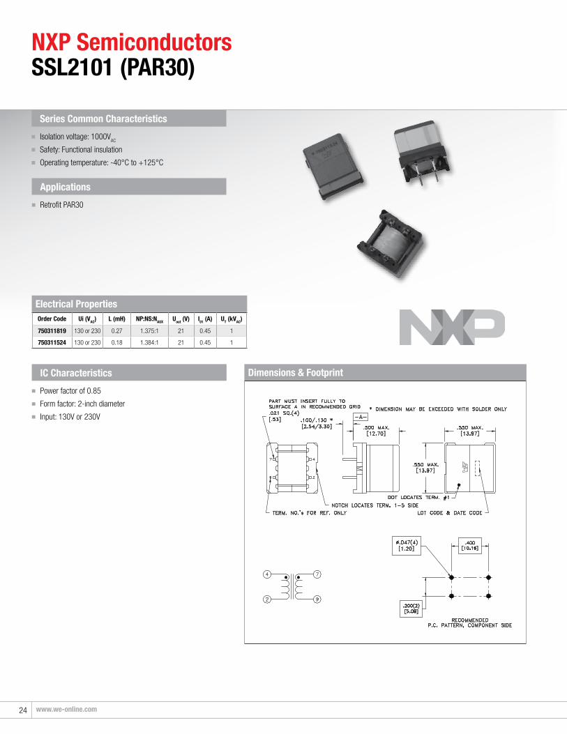
NXP SemiconductorsSSL2101 (PAR30)
Dimensions & Footprint
Applications
n Retrofit PAR30
Series Common Characteristics
n Isolation voltage: 1000VAC
n Safety: Functional insulation
n Operating temperature: -40°C to +125°C
IC Characteristics
n Power factor of 0.85
n Form factor: 2-inch diameter
n Input: 130V or 230V
Electrical PropertiesOrder Code Ui (VAC) L (mH) NP:NS:NAUX Uout (V) I01 (A) UT (kVAC)
750311819 130 or 230 0.27 1.375:1 21 0.45 1
750311524 130 or 230 0.18 1.384:1 21 0.45 1
www.we-online.com24
Dimensions & Footprint
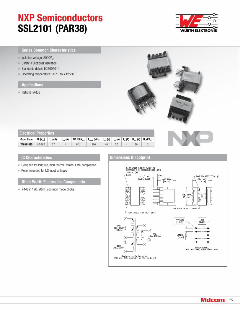
NXP SemiconductorsSSL2101 (PAR38)
Applications
n Retrofit PAR38
Series Common Characteristics
n Isolation voltage: 2000VAC
n Safety: Functional insulation
n Standards detail: IEC60950-1
n Operating temperature: -40°C to +125°C
IC Characteristics
n Designed for long life, high thermal stress, EMC compliance
n Recommended for US input voltages
Electrical PropertiesOrder Code Ui (VAC) L (mH) ISAT (A) NP:NS:NAUX fswitch (kHz) Uout (V) I01 (A) I02 (A) UAUX (V) UT (kVAC)
750311525 85-265 0.7 1 6:2:1 100 40 0.5 - 20 2
Other Wurth Electronics Components
n 744821120: 20mH common mode choke
25
Dimensions & Footprint
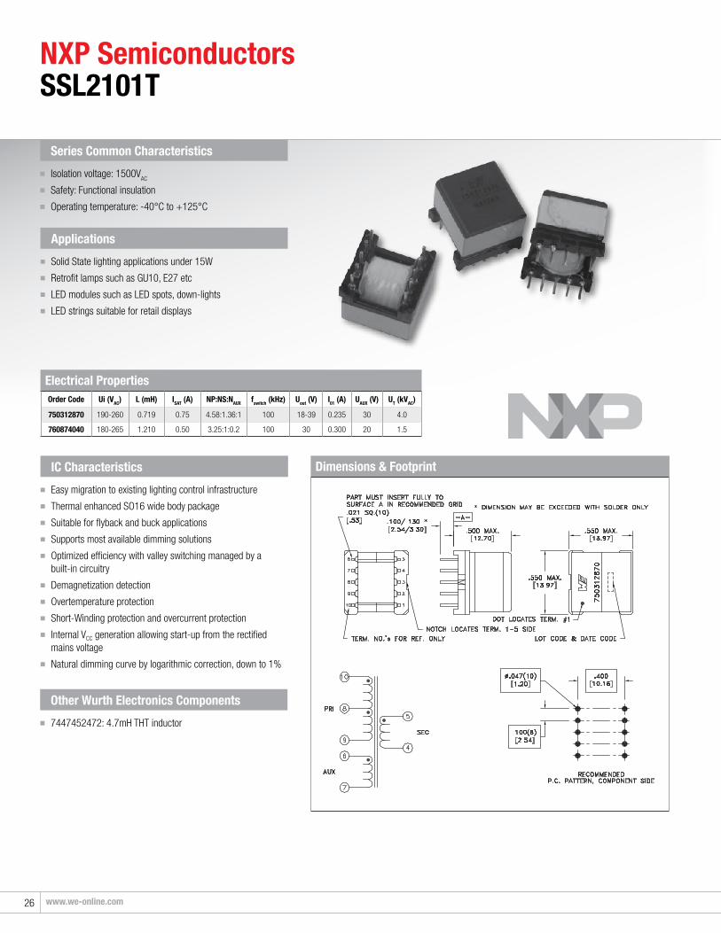
Applications
n Solid State lighting applications under 15W
n Retrofit lamps such as GU10, E27 etc
n LED modules such as LED spots, down-lights
n LED strings suitable for retail displays
Series Common Characteristics
n Isolation voltage: 1500VAC
n Safety: Functional insulation
n Operating temperature: -40°C to +125°C
NXP SemiconductorsSSL2101T
Other Wurth Electronics Components
n 7447452472: 4.7mH THT inductor
IC Characteristics
n Easy migration to existing lighting control infrastructure
n Thermal enhanced SO16 wide body package
n Suitable for flyback and buck applications
n Supports most available dimming solutions
n Optimized efficiency with valley switching managed by a built-in circuitry
n Demagnetization detection
n Overtemperature protection
n Short-Winding protection and overcurrent protection
n Internal VCC generation allowing start-up from the rectified mains voltage
n Natural dimming curve by logarithmic correction, down to 1%
Electrical PropertiesOrder Code Ui (VAC) L (mH) ISAT (A) NP:NS:NAUX fswitch (kHz) Uout (V) I01 (A) UAUX (V) UT (kVAC)
750312870 190-260 0.719 0.75 4.58:1.36:1 100 18-39 0.235 30 4.0
760874040 180-265 1.210 0.50 3.25:1:0.2 100 30 0.300 20 1.5
www.we-online.com26
Dimensions & Footprint
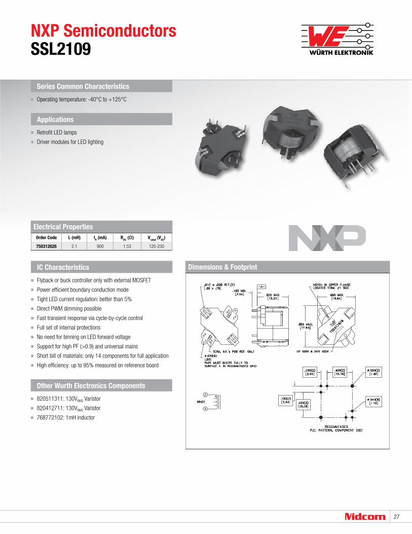
Electrical PropertiesOrder Code L (mH) IR (mA) RDC (Ω) Vrated (VAC)
750312626 2.1 900 1.53 120-230
Applications
n Retrofit LED lamps
n Driver modules for LED lighting
Series Common Characteristics
n Operating temperature: -40°C to +125°C
NXP SemiconductorsSSL2109
Other Wurth Electronics Components
n 820511311: 130VRMS Varistor
n 820412711: 130VRMS Varistor
n 768772102: 1mH inductor
IC Characteristics
n Flyback or buck controller only with external MOSFET
n Power efficient boundary conduction mode
n Tight LED current regulation: better than 5%
n Direct PWM dimming possible
n Fast transient response via cycle-by-cycle control
n Full set of internal protections
n No need for binning on LED forward voltage
n Support for high PF (>0.9) and universal mains
n Short bill of materials: only 14 components for full application
n High efficiency: up to 95% measured on reference board
27
Dimensions & Footprint
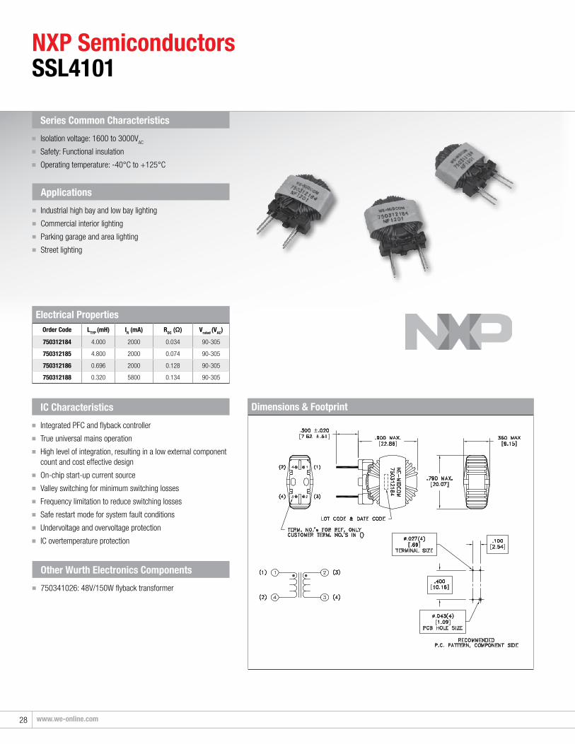
Electrical PropertiesOrder Code LTYP (mH) IR (mA) RDC (Ω) Vrated (VAC)
750312184 4.000 2000 0.034 90-305
750312185 4.800 2000 0.074 90-305
750312186 0.696 2000 0.128 90-305
750312188 0.320 5800 0.134 90-305
Applications
n Industrial high bay and low bay lighting
n Commercial interior lighting
n Parking garage and area lighting
n Street lighting
Series Common Characteristics
n Isolation voltage: 1600 to 3000VAC
n Safety: Functional insulation
n Operating temperature: -40°C to +125°C
NXP SemiconductorsSSL4101
IC Characteristics
n Integrated PFC and flyback controller
n True universal mains operation
n High level of integration, resulting in a low external component count and cost effective design
n On-chip start-up current source
n Valley switching for minimum switching losses
n Frequency limitation to reduce switching losses
n Safe restart mode for system fault conditions
n Undervoltage and overvoltage protection
n IC overtemperature protection
Other Wurth Electronics Components
n 750341026: 48V/150W flyback transformer
www.we-online.com28
Dimensions & Footprint
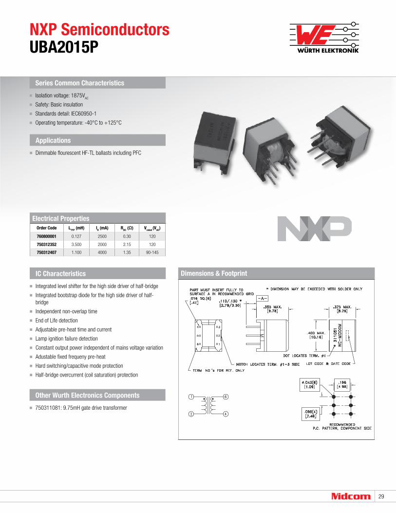
Applications
n Dimmable flourescent HF-TL ballasts including PFC
Series Common Characteristics
n Isolation voltage: 1875VAC
n Safety: Basic insulation
n Standards detail: IEC60950-1
n Operating temperature: -40°C to +125°C
NXP SemiconductorsUBA2015P
IC Characteristics
n Integrated level shifter for the high side driver of half-bridge
n Integrated bootstrap diode for the high side driver of half- bridge
n Independent non-overlap time
n End of Life detection
n Adjustable pre-heat time and current
n Lamp ignition failure detection
n Constant output power independent of mains voltage variation
n Adustable fixed frequeny pre-heat
n Hard switching/capacitive mode protection
n Half-bridge overcurrent (coil saturation) protection
Electrical PropertiesOrder Code LTYP (mH) IR (mA) RDC (Ω) Vrated (VAC)
760800001 0.127 2500 0.30 120
750312352 3.500 2000 2.15 120
750312407 1.100 4000 1.35 90-145
Other Wurth Electronics Components
n 750311081: 9.75mH gate drive transformer
29
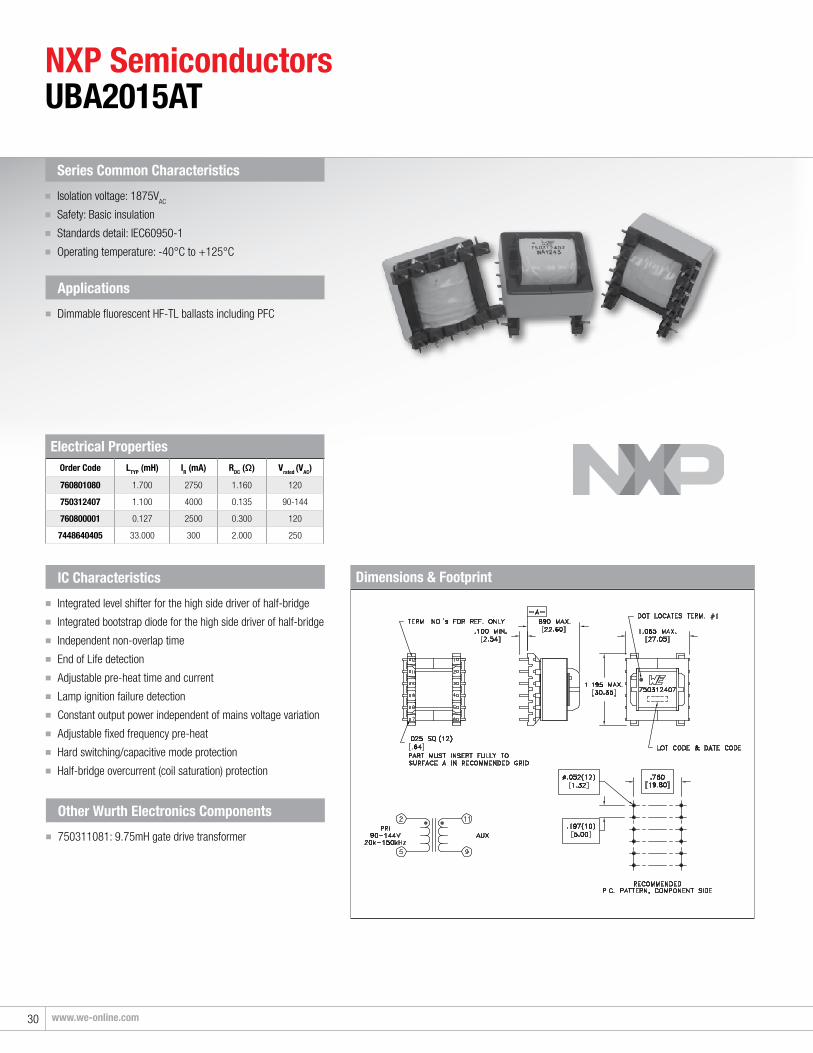
Dimensions & Footprint
Applications
n Dimmable fluorescent HF-TL ballasts including PFC
Series Common Characteristics
n Isolation voltage: 1875VAC
n Safety: Basic insulation
n Standards detail: IEC60950-1
n Operating temperature: -40°C to +125°C
NXP SemiconductorsUBA2015AT
IC Characteristics
n Integrated level shifter for the high side driver of half-bridge
n Integrated bootstrap diode for the high side driver of half-bridge
n Independent non-overlap time
n End of Life detection
n Adjustable pre-heat time and current
n Lamp ignition failure detection
n Constant output power independent of mains voltage variation
n Adjustable fixed frequency pre-heat
n Hard switching/capacitive mode protection
n Half-bridge overcurrent (coil saturation) protection
Electrical PropertiesOrder Code LTYP (mH) IR (mA) RDC (Ω) Vrated (VAC)
760801080 1.700 2750 1.160 120
750312407 1.100 4000 0.135 90-144
760800001 0.127 2500 0.300 120
7448640405 33.000 300 2.000 250
Other Wurth Electronics Components
n 750311081: 9.75mH gate drive transformer
www.we-online.com30
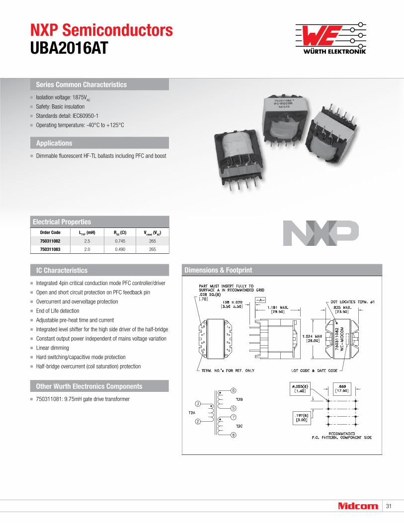
Dimensions & Footprint
Applications
n Dimmable fluorescent HF-TL ballasts including PFC and boost
Series Common Characteristics
n Isolation voltage: 1875VAC
n Safety: Basic insulation
n Standards detail: IEC60950-1
n Operating temperature: -40°C to +125°C
NXP SemiconductorsUBA2016AT
IC Characteristics
n Integrated 4pin critical conduction mode PFC controller/driver
n Open and short circuit protection on PFC feedback pin
n Overcurrent and overvoltage protection
n End of Life detection
n Adjustable pre-heat time and current
n Integrated level shifter for the high side driver of the half-bridge
n Constant output power independent of mains voltage variation
n Linear dimming
n Hard switching/capacitive mode protection
n Half-bridge overcurrent (coil saturation) protection
Electrical PropertiesOrder Code LTYP (mH) RDC (Ω) Vrated (VAC)
750311082 2.5 0.745 265
750311083 2.0 0.490 265
Other Wurth Electronics Components
n 750311081: 9.75mH gate drive transformer
31
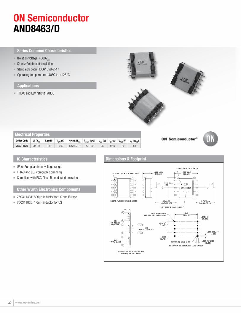
ON SemiconductorAND8463/D
Dimensions & Footprint
Applications
n TRIAC and ELV retrofit PAR30
Series Common Characteristics
n Isolation voltage: 4500VAC
n Safety: Reinforced insulation
n Standards detail: IEC61558-2-17
n Operating temperature: -40°C to +125°C
IC Characteristics
n US or European input voltage range
n TRIAC and ELV compatible dimming
n Compliant with FCC Class B conducted emissions
Electrical PropertiesOrder Code Ui (VAC) L (mH) ISAT (A) NP:NS:NAUX fswitch (kHz) Uout (V) I01 (A) UAUX (V) UT (kVAC)
750311620 20-135 1.9 0.62 1.57:1.31:1 53-120 25 0.45 19 4.5
Other Wurth Electronics Components
n 750311431: 800μH inductor for US and Europe
n 750311826: 1.6mH inductor for US
www.we-online.com32
Dimensions & Footprint
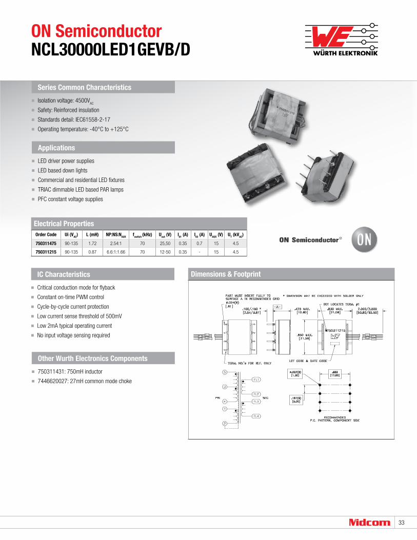
ON SemiconductorNCL30000LED1GEVB/D
Series Common Characteristics
n Isolation voltage: 4500VAC
n Safety: Reinforced insulation
n Standards detail: IEC61558-2-17
n Operating temperature: -40°C to +125°C
Other Wurth Electronics Components
n 750311431: 750mH inductor
n 7446620027: 27mH common mode choke
Applications
n LED driver power supplies
n LED based down lights
n Commercial and residential LED fixtures
n TRIAC dimmable LED based PAR lamps
n PFC constant voltage supplies
IC Characteristics
n Critical conduction mode for flyback
n Constant on-time PWM control
n Cycle-by-cycle current protection
n Low current sense threshold of 500mV
n Low 2mA typical operating current
n No input voltage sensing required
Electrical PropertiesOrder Code Ui (VAC) L (mH) NP:NS:NAUX fswitch (kHz) Uout (V) I01 (A) I02 (A) UAUX (V) UT (kVAC)
750311475 90-135 1.72 2.54:1 70 25,50 0.35 0.7 15 4.5
750311215 90-135 0.87 6.6:1:1.66 70 12-50 0.35 - 15 4.5
33
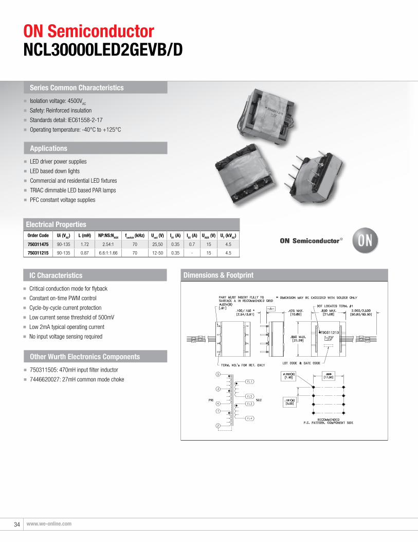
ON SemiconductorNCL30000LED2GEVB/D
Dimensions & Footprint
Series Common Characteristics
n Isolation voltage: 4500VAC
n Safety: Reinforced insulation
n Standards detail: IEC61558-2-17
n Operating temperature: -40°C to +125°C
Other Wurth Electronics Components
n 750311505: 470mH input filter inductor
n 7446620027: 27mH common mode choke
Applications
n LED driver power supplies
n LED based down lights
n Commercial and residential LED fixtures
n TRIAC dimmable LED based PAR lamps
n PFC constant voltage supplies
IC Characteristics
n Critical conduction mode for flyback
n Constant on-time PWM control
n Cycle-by-cycle current protection
n Low current sense threshold of 500mV
n Low 2mA typical operating current
n No input voltage sensing required
Electrical PropertiesOrder Code Ui (VAC) L (mH) NP:NS:NAUX fswitch (kHz) Uout (V) I01 (A) I02 (A) UAUX (V) UT (kVAC)
750311475 90-135 1.72 2.54:1 70 25,50 0.35 0.7 15 4.5
750311215 90-135 0.87 6.6:1:1.66 70 12-50 0.35 - 15 4.5
www.we-online.com34
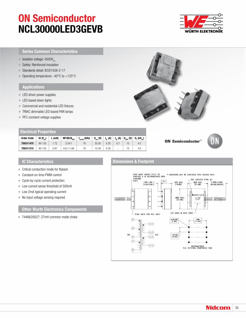
ON SemiconductorNCL30000LED3GEVB
Dimensions & Footprint
Applications
n LED driver power supplies
n LED based down lights
n Commercial and residential LED fixtures
n TRIAC dimmable LED based PAR lamps
n PFC constant voltage supplies
Series Common Characteristics
n Isolation voltage: 4500VAC
n Safety: Reinforced insulation
n Standards detail: IEC61558-2-17
n Operating temperature: -40°C to +125°C
IC Characteristics
n Critical conduction mode for flyback
n Constant on-time PWM control
n Cycle-by-cycle current protection
n Low current sense threshold of 500mV
n Low 2mA typical operating current
n No input voltage sensing required
Other Wurth Electronics Components
n 7446620027: 27mH common mode choke
Electrical PropertiesOrder Code Ui (VAC) L (mH) NP:NS:NAUX fswitch (kHz) Uout (V) I01 (A) I02 (A) UAUX (V) UT (kVAC)
750311475 90-135 1.72 2.54:1 70 25,50 0.35 0.7 15 4.5
750311215 90-135 0.87 6.6:1:1.66 70 12-50 0.35 - 15 4.5
35
Dimensions & Footprint
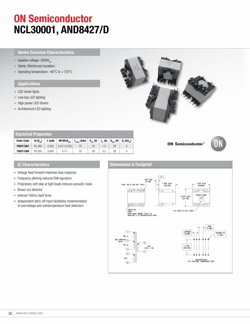
ON SemiconductorNCL30001, AND8427/D
Applications
n LED street lights
n Low bay LED lighting
n High power LED drivers
n Architectural LED lighting
Series Common Characteristics
n Isolation voltage: 3000VAC
n Safety: Reinforced insulation
n Operating temperature: -40°C to +125°C
IC Characteristics
n Voltage feed forward improves loop response
n Frequency jittering reduces EMI signature
n Proprietary soft-skip at light loads reduces acoustic noise
n Brown out detector
n Internal 160ms fault timer
n Independent latch-off input facilitates implementation of overvoltage and overtemperature fault detectors
Electrical PropertiesOrder Code Ui (VAC) L (mH) NP:NS:NAUX fswitch (kHz) Uout (V) I01 (A) UAUX (V) UT (kVAC)
750311267 85-265 0.625 2.24:1:0.232 70 50 1.5 28 3
750311269 85-265 0.600 4:1:1 70 28 3.2 28 3
www.we-online.com36
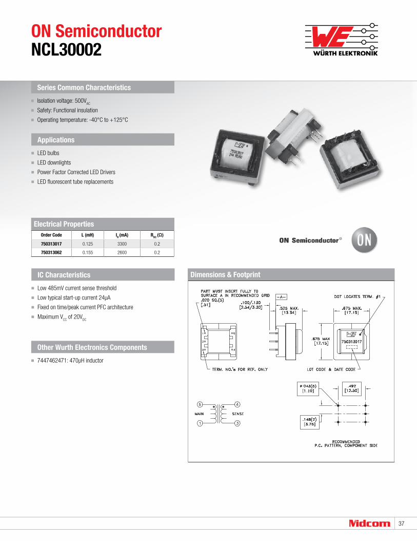
Dimensions & Footprint
Applications
n LED bulbs
n LED downlights
n Power Factor Corrected LED Drivers
n LED fluorescent tube replacements
Series Common Characteristics
n Isolation voltage: 500VAC
n Safety: Functional insulation
n Operating temperature: -40°C to +125°C
ON SemiconductorNCL30002
Other Wurth Electronics Components
n 7447462471: 470µH inductor
IC Characteristics
n Low 485mV current sense threshold
n Low typical start-up current 24μA
n Fixed on time/peak current PFC architecture
n Maximum VCC
of 20VDC
Electrical PropertiesOrder Code L (mH) IR (mA) RDC (Ω)
750313017 0.125 3300 0.2
750313062 0.155 2600 0.2
37
Dimensions & Footprint
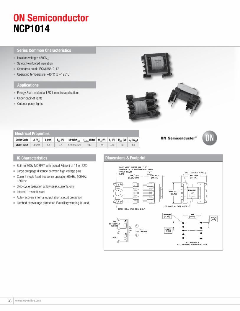
ON SemiconductorNCP1014
Applications
n Energy Star residential LED luminaire applications
n Under-cabinet lights
n Outdoor porch lights
Series Common Characteristics
n Isolation voltage: 4500VAC
n Safety: Reinforced insulation
n Standards detail: IEC61558-2-17
n Operating temperature: -40°C to +125°C
IC Characteristics
n Built-in 700V MOSFET with typical Rds(on) of 11 or 22Ω
n Large creepage distance between high voltage pins
n Current mode fixed frequency operation 65kHz, 100kHz, 130kHz
n Skip-cycle operation at low peak currents only
n Internal 1ms soft-start
n Auto-recovery internal output short circuit protection
n Latched overvoltage protection if auxiliary winding is used
Electrical PropertiesOrder Code Ui (VAC) L (mH) ISAT (A) NP:NS:NAUX fswitch (kHz) Uout (V) I01 (A) UAUX (V) UT (kVAC)
750811042 90-265 1.8 0.4 5.25:1:0.123 100 24 0.36 20 4.5
www.we-online.com38
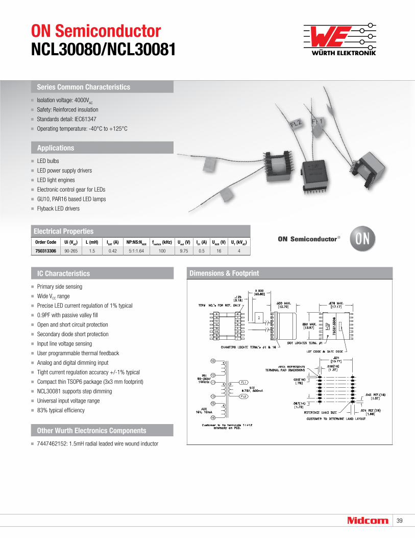
Dimensions & Footprint
Applications
n LED bulbs
n LED power supply drivers
n LED light engines
n Electronic control gear for LEDs
n GU10, PAR16 based LED lamps
n Flyback LED drivers
Series Common Characteristics
n Isolation voltage: 4000VAC
n Safety: Reinforced insulation
n Standards detail: IEC61347
n Operating temperature: -40°C to +125°C
ON SemiconductorNCL30080/NCL30081
Other Wurth Electronics Components
n 7447462152: 1.5mH radial leaded wire wound inductor
IC Characteristics
n Primary side sensing
n Wide VCC range
n Precise LED current regulation of 1% typical
n 0.9PF with passive valley fill
n Open and short circuit protection
n Secondary diode short protection
n Input line voltage sensing
n User programmable thermal feedback
n Analog and digital dimming input
n Tight current regulation accuracy +/-1% typical
n Compact thin TSOP6 package (3x3 mm footprint)
n NCL30081 supports step dimming
n Universal input voltage range
n 83% typical efficiency
Electrical PropertiesOrder Code Ui (VAC) L (mH) ISAT (A) NP:NS:NAUX fswitch (kHz) Uout (V) I01 (A) UAUX (V) UT (kVAC)
750313306 90-265 1.5 0.42 5:1:1.64 100 9.75 0.5 16 4
39
Dimensions & Footprint
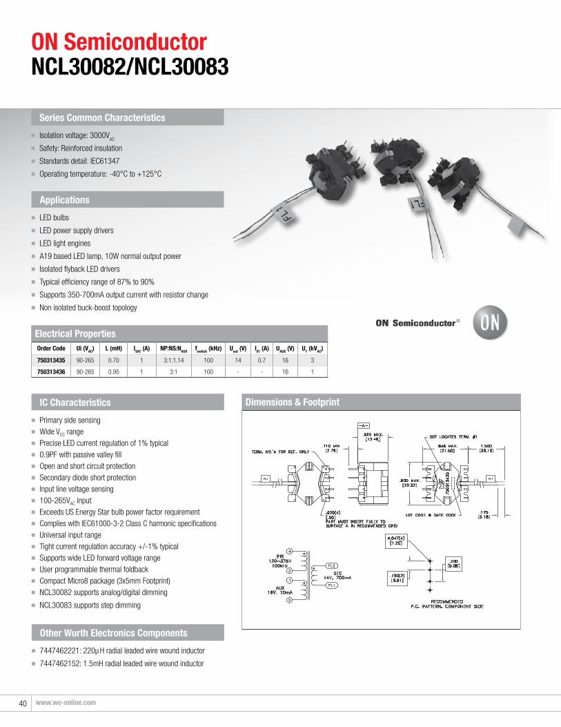
Applications
n LED bulbs
n LED power supply drivers
n LED light engines
n A19 based LED lamp, 10W normal output power
n Isolated flyback LED drivers
n Typical efficiency range of 87% to 90%
n Supports 350-700mA output current with resistor change
n Non isolated buck-boost topology
Series Common Characteristics
n Isolation voltage: 3000VAC
n Safety: Reinforced insulation
n Standards detail: IEC61347
n Operating temperature: -40°C to +125°C
ON SemiconductorNCL30082/NCL30083
Other Wurth Electronics Components
n 7447462221: 220μ H radial leaded wire wound inductor
n 7447462152: 1.5mH radial leaded wire wound inductor
IC Characteristics
n Primary side sensing n Wide VCC range n Precise LED current regulation of 1% typical n 0.9PF with passive valley fill n Open and short circuit protection n Secondary diode short protection n Input line voltage sensingn 100-265VAC inputn Exceeds US Energy Star bulb power factor requirementn Complies with IEC61000-3-2 Class C harmonic specificationsn Universal input rangen Tight current regulation accuracy +/-1% typicaln Supports wide LED forward voltage rangen User programmable thermal foldbackn Compact Micro8 package (3x5mm Footprint)n NCL30082 supports analog/digital dimming
n NCL30083 supports step dimming
Electrical PropertiesOrder Code Ui (VAC) L (mH) ISAT (A) NP:NS:NAUX fswitch (kHz) Uout (V) I01 (A) UAUX (V) UT (kVAC)
750313435 90-265 0.70 1 3:1:1.14 100 14 0.7 16 3
750313436 90-265 0.95 1 3:1 100 - - 16 1
www.we-online.com40
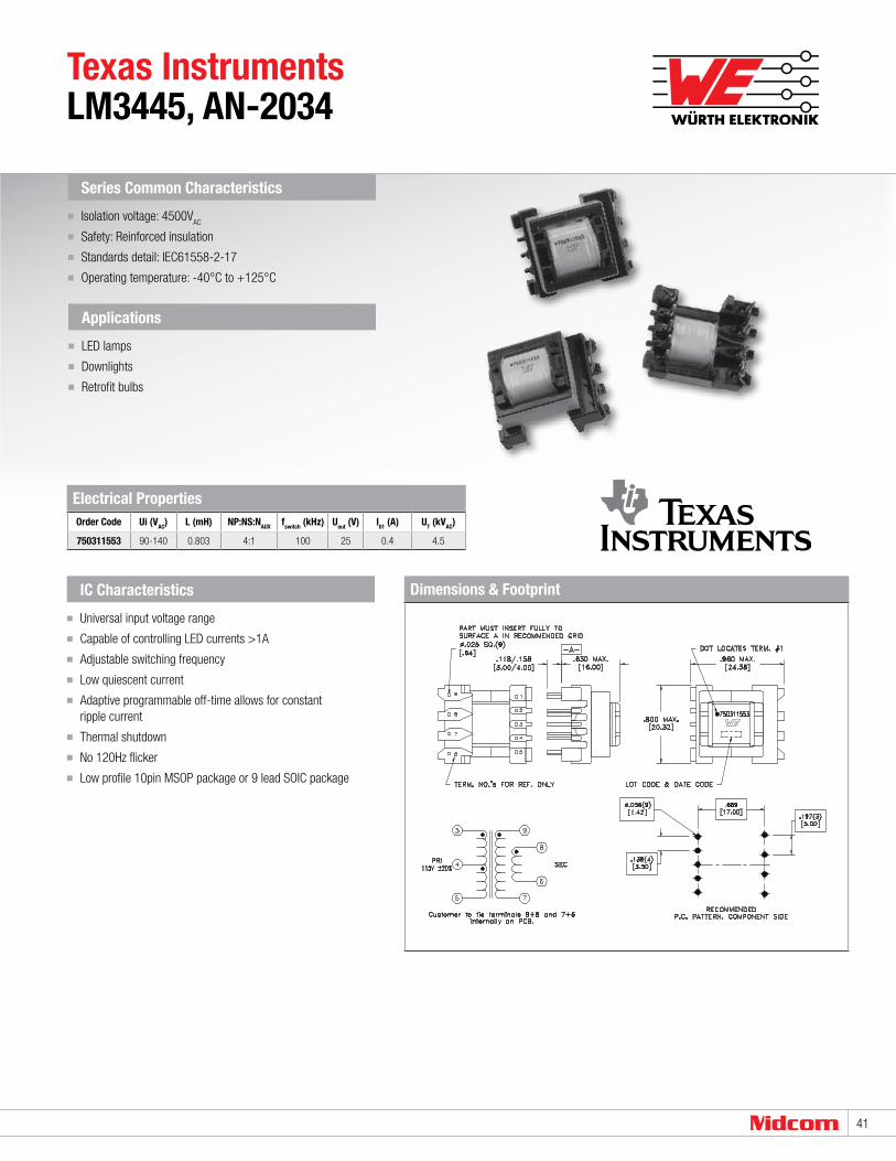
Texas InstrumentsLM3445, AN-2034
Dimensions & Footprint
Applications
n LED lamps
n Downlights
n Retrofit bulbs
Series Common Characteristics
n Isolation voltage: 4500VAC
n Safety: Reinforced insulation
n Standards detail: IEC61558-2-17
n Operating temperature: -40°C to +125°C
IC Characteristics
n Universal input voltage range
n Capable of controlling LED currents >1A
n Adjustable switching frequency
n Low quiescent current
n Adaptive programmable off-time allows for constant ripple current
n Thermal shutdown
n No 120Hz flicker
n Low profile 10pin MSOP package or 9 lead SOIC package
Electrical PropertiesOrder Code Ui (VAC) L (mH) NP:NS:NAUX fswitch (kHz) Uout (V) I01 (A) UT (kVAC)
750311553 90-140 0.803 4:1 100 25 0.4 4.5
41
Dimensions & Footprint
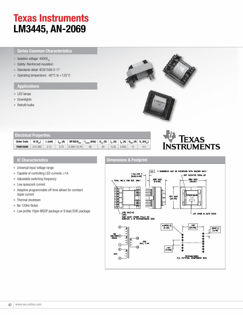
Texas InstrumentsLM3445, AN-2069
Applications
n LED lamps
n Downlights
n Retrofit bulbs
Series Common Characteristics
n Isolation voltage: 4500VAC
n Safety: Reinforced insulation
n Standards detail: IEC61558-2-17
n Operating temperature: -40°C to +125°C
IC Characteristics
n Universal input voltage range
n Capable of controlling LED currents >1A
n Adjustable switching frequency
n Low quiescent current
n Adaptive programmable off-time allows for constant ripple current
n Thermal shutdown
n No 120Hz flicker
n Low profile 10pin MSOP package or 9 lead SOIC package
Electrical PropertiesOrder Code Ui (VAC) L (mH) ISAT (A) NP:NS:NAUX fswitch (kHz) Uout (V) I01 (A) I02 (A) UAUX (V) UT (kVAC)
750815040 210-265 2.12 0.75 5.384:1:0.76 65 20 0.35 0.002 15 4.5
www.we-online.com42
Dimensions & Footprint
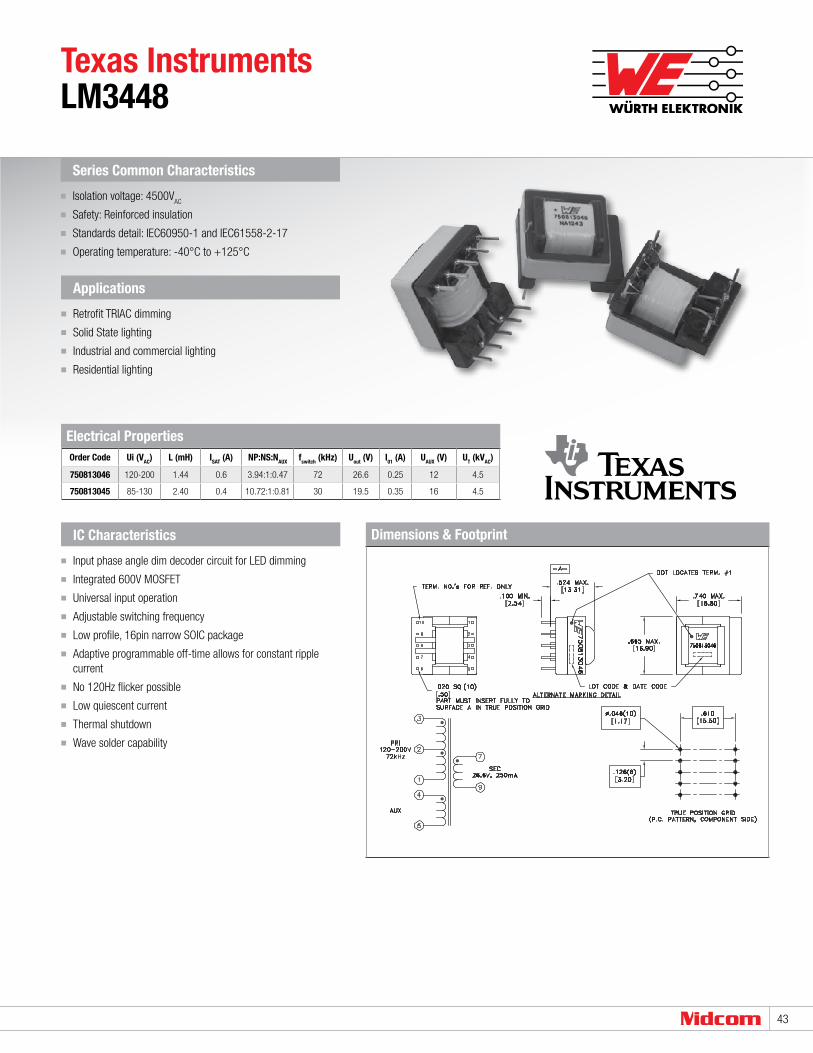
Applications
n Retrofit TRIAC dimming
n Solid State lighting
n Industrial and commercial lighting
n Residential lighting
Series Common Characteristics
n Isolation voltage: 4500VAC
n Safety: Reinforced insulation
n Standards detail: IEC60950-1 and IEC61558-2-17
n Operating temperature: -40°C to +125°C
Texas InstrumentsLM3448
IC Characteristics
n Input phase angle dim decoder circuit for LED dimming
n Integrated 600V MOSFET
n Universal input operation
n Adjustable switching frequency
n Low profile, 16pin narrow SOIC package
n Adaptive programmable off-time allows for constant ripple current
n No 120Hz flicker possible
n Low quiescent current
n Thermal shutdown
n Wave solder capability
Electrical PropertiesOrder Code Ui (VAC) L (mH) ISAT (A) NP:NS:NAUX fswitch (kHz) Uout (V) I01 (A) UAUX (V) UT (kVAC)
750813046 120-200 1.44 0.6 3.94:1:0.47 72 26.6 0.25 12 4.5
750813045 85-130 2.40 0.4 10.72:1:0.81 30 19.5 0.35 16 4.5
43
Dimensions & Footprint
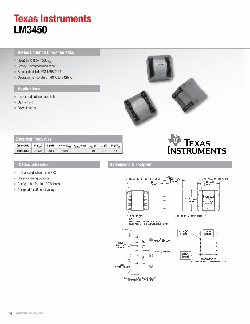
Texas InstrumentsLM3450
Applications
n Indoor and outdoor area lights
n Bay lighting
n Down lighting
Series Common Characteristics
n Isolation voltage: 4500VAC
n Safety: Reinforced insulation
n Standards detail: IEC61558-2-17
n Operating temperature: -40°C to +125°C
IC Characteristics
n Critical conduction mode PFC
n Phase dimming decoder
n Configurable for 10-100W loads
n Designed for US input voltage
Electrical PropertiesOrder Code Ui (VAC) L (mH) NP:NS:NAUX fswitch (kHz) Uout (V) I01 (A) UT (kVAC)
750813550 90-135 0.8035 2.54:1 100 50 0.35 4.5
www.we-online.com44
Dimensions & Footprint
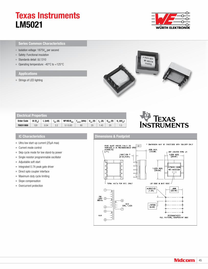
Applications
n Strings of LED lighting
Series Common Characteristics
n Isolation voltage: 1875VAC
per second
n Safety: Functional insulation
n Standards detail: UL1310
n Operating temperature: -40°C to +125°C
Texas InstrumentsLM5021
IC Characteristics
n Ultra low start-up current (25μA max)
n Current mode control
n Skip cycle mode for low stand-by power
n Single resistor programmable oscillator
n Adjustable soft start
n Integrated 0.7A peak gate driver
n Direct opto coupler interface
n Maximum duty cycle limiting
n Slope compensation
n Overcurrent protection
Electrical PropertiesOrder Code Ui (VAC) L (mH) ISAT (A) NP:NS:NAUX fswitch (kHz) Uout (V) I01 (A) UAUX (V) UT (kVAC)
750311959 120 0.54 2.2 5:1:0.83 80 20 1.43 20 1.5
45
Dimensions & Footprint
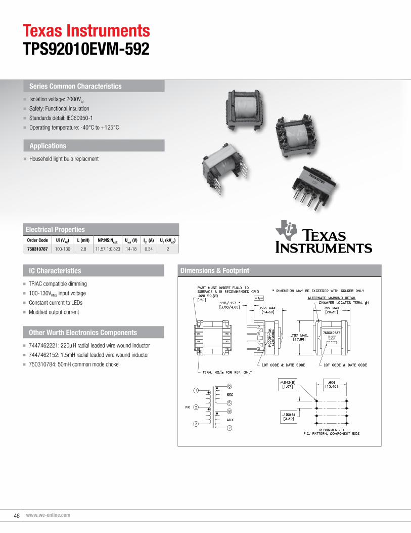
Texas InstrumentsTPS92010EVM-592
Applications
n Household light bulb replacment
Series Common Characteristics
n Isolation voltage: 2000VAC
n Safety: Functional insulation
n Standards detail: IEC60950-1
n Operating temperature: -40°C to +125°C
IC Characteristics
n TRIAC compatible dimming
n 100-130VRMS input voltage
n Constant current to LEDs
n Modified output current
Electrical PropertiesOrder Code Ui (VAC) L (mH) NP:NS:NAUX Uout (V) I01 (A) UT (kVAC)
750310787 100-130 2.8 11.57:1:0.823 14-18 0.34 2
Other Wurth Electronics Components
n 7447462221: 220μ H radial leaded wire wound inductor
n 7447462152: 1.5mH radial leaded wire wound inductor
n 750310784: 50mH common mode choke
www.we-online.com46
Dimensions & Footprint
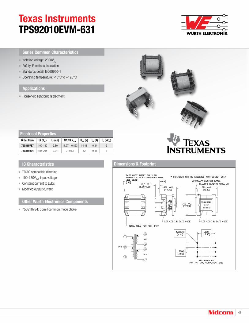
Texas InstrumentsTPS92010EVM-631
Applications
n Household light bulb replacment
Series Common Characteristics
n Isolation voltage: 2000VAC
n Safety: Functional insulation
n Standards detail: IEC60950-1
n Operating temperature: -40°C to +125°C
IC Characteristics
n TRIAC compatible dimming
n 100-130VRMS input voltage
n Constant current to LEDs
n Modified output current
Electrical PropertiesOrder Code Ui (VAC) L (mH) NP:NS:NAUX Uout (V) I01 (A) UT (kVAC)
750310787 100-130 2.80 11.57:1:0.823 14-18 0.34 2
750310334 185-265 9.94 01:01.2 12 0.41 2
Other Wurth Electronics Components
n 750310784: 50mH common mode choke
47
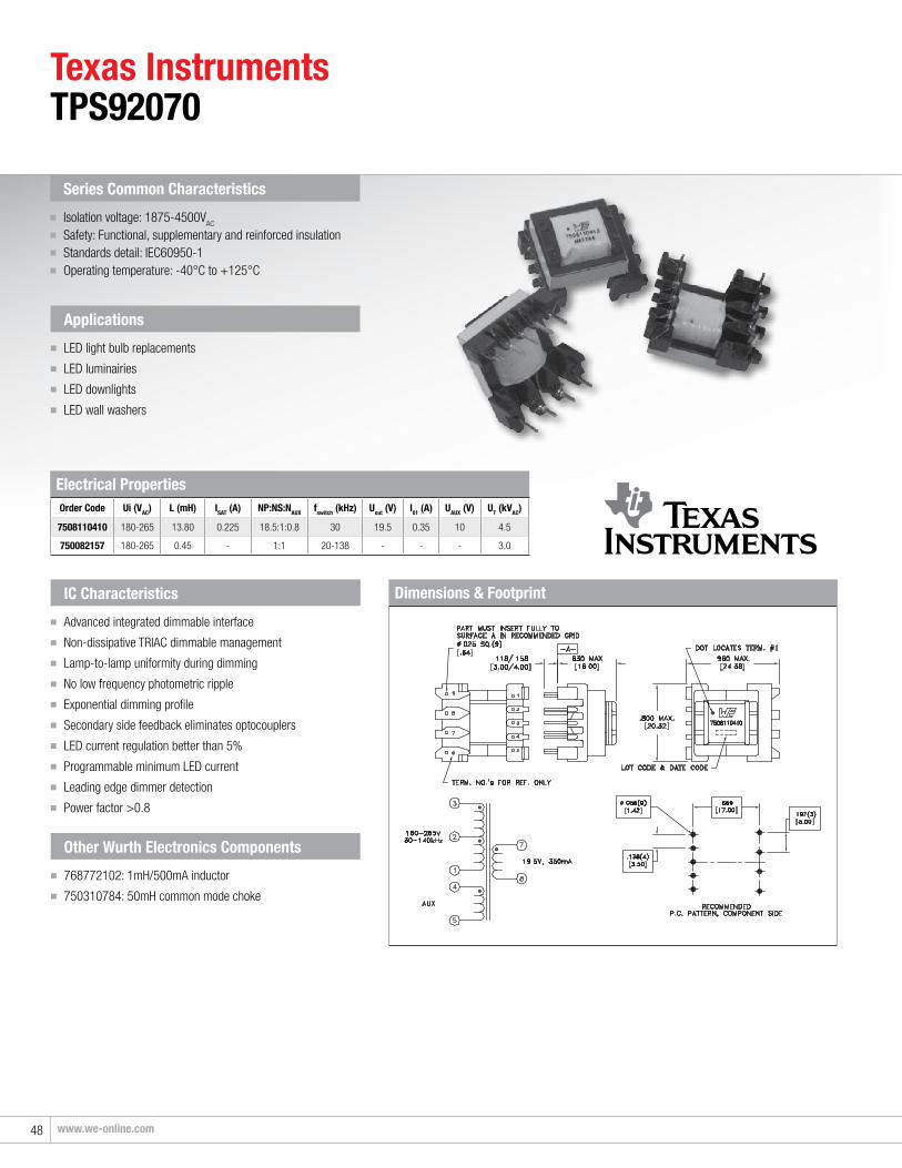
Dimensions & Footprint
Applications
n LED light bulb replacements
n LED luminairies
n LED downlights
n LED wall washers
Series Common Characteristics
n Isolation voltage: 1875-4500VAC
n Safety: Functional, supplementary and reinforced insulation n Standards detail: IEC60950-1 n Operating temperature: -40°C to +125°C
Texas InstrumentsTPS92070
Other Wurth Electronics Components
n 768772102: 1mH/500mA inductor
n 750310784: 50mH common mode choke
IC Characteristics
n Advanced integrated dimmable interface
n Non-dissipative TRIAC dimmable management
n Lamp-to-lamp uniformity during dimming
n No low frequency photometric ripple
n Exponential dimming profile
n Secondary side feedback eliminates optocouplers
n LED current regulation better than 5%
n Programmable minimum LED current
n Leading edge dimmer detection
n Power factor >0.8
Electrical PropertiesOrder Code Ui (VAC) L (mH) ISAT (A) NP:NS:NAUX fswitch (kHz) Uout (V) I01 (A) UAUX (V) UT (kVAC)
7508110410 180-265 13.80 0.225 18.5:1:0.8 30 19.5 0.35 10 4.5
750082157 180-265 0.45 - 1:1 20-138 - - - 3.0
www.we-online.com48
Dimensions & Footprint
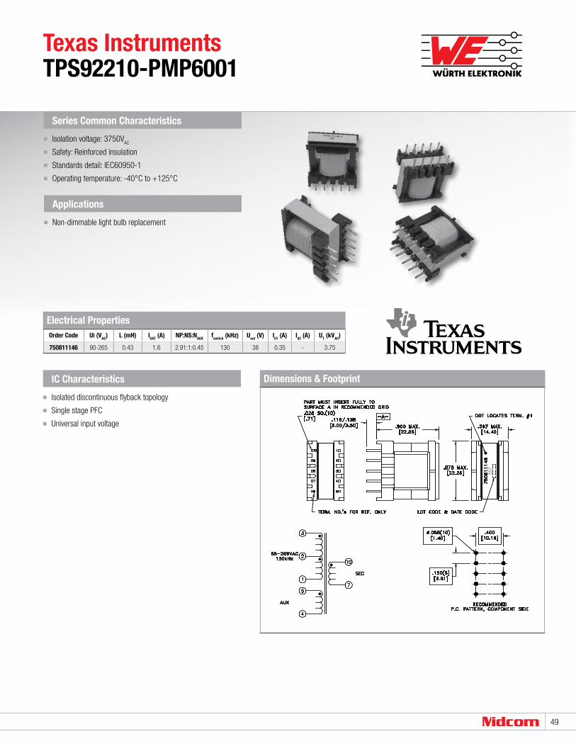
Texas InstrumentsTPS92210-PMP6001
Applications
n Non-dimmable light bulb replacement
Series Common Characteristics
n Isolation voltage: 3750VAC
n Safety: Reinforced insulation
n Standards detail: IEC60950-1
n Operating temperature: -40°C to +125°C
IC Characteristics
n Isolated discontinuous flyback topology
n Single stage PFC
n Universal input voltage
Electrical PropertiesOrder Code Ui (VAC) L (mH) ISAT (A) NP:NS:NAUX fswitch (kHz) Uout (V) I01 (A) I02 (A) UT (kVAC)
750811146 90-265 0.43 1.6 2.91:1:0.45 130 38 0.35 - 3.75
49
1
3
2
10
5
4
7
Aux
88-269VAC130kHz SEC
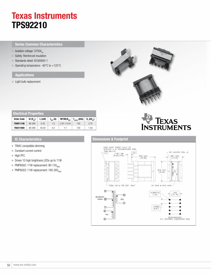
Texas InstrumentsTPS92210
Dimensions & Footprint
Applications
n Light bulb replacement
Series Common Characteristics
n Isolation voltage: 3750VAC
n Safety: Reinforced insulation
n Standards detail: IEC60950-1
n Operating temperature: -40°C to +125°C
IC Characteristics
n TRIAC compatible dimming
n Constant current control
n High PFC
n Drives 10 high brightness LEDs up to 11W
n PMP6002: 11W replacement: 90-135RMS
n PMP6003: 11W replacement: 180-265RMS
Electrical PropertiesOrder Code Ui (VAC) L (mH) ISAT (A) NP:NS:NAUX fswitch (kHz) UT (kVAC)
750811148 88-269 0.43 1.5 2.91:1:0.54 130 3.75
750311650 88-269 45.00 0.2 1:1 130 1.50
www.we-online.com50
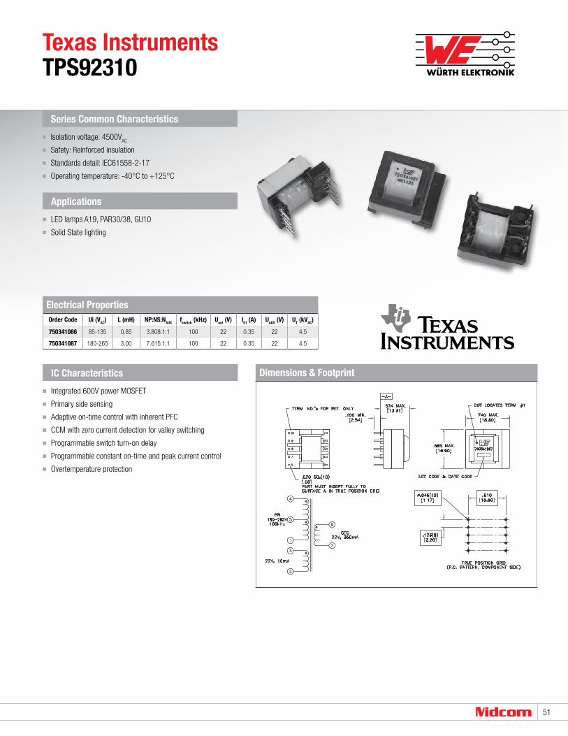
Dimensions & Footprint
Applications
n LED lamps A19, PAR30/38, GU10
n Solid State lighting
Series Common Characteristics
n Isolation voltage: 4500VAC
n Safety: Reinforced insulation
n Standards detail: IEC61558-2-17
n Operating temperature: -40°C to +125°C
Texas InstrumentsTPS92310
IC Characteristics
n Integrated 600V power MOSFET
n Primary side sensing
n Adaptive on-time control with inherent PFC
n CCM with zero current detection for valley switching
n Programmable switch turn-on delay
n Programmable constant on-time and peak current control
n Overtemperature protection
Electrical PropertiesOrder Code Ui (VAC) L (mH) NP:NS:NAUX fswitch (kHz) Uout (V) I01 (A) UAUX (V) UT (kVAC)
750341086 85-135 0.85 3.808:1:1 100 22 0.35 22 4.5
750341087 180-265 3.00 7.615:1:1 100 22 0.35 22 4.5
51
www.we-online.com
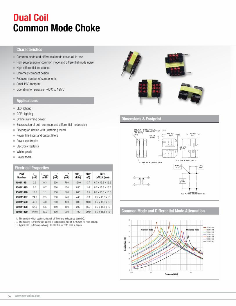
Dual CoilCommon Mode Choke
1. The current which causes 20% roll off from the inductance at no DC.2. The heating current which causes a temperature rise of 40°C with no heat sinking.3. Typical DCR is for one coil only; double this for both coils in series.
Applications
n LED lighting
n CCFL lighting
n Offline switching power
n Suppression of both common and differential mode noise
n Filtering on device with unstable ground
n Power line input and output filters
n Power electronics
n Electronic ballasts
n White goods
n Power tools
Characteristics
n Common mode and differential mode choke all-in-one
n High suppression of common mode and differential mode noise
n High differential inductance
n Extremely compact design
n Reduces number of components
n Small PCB footprint
n Operating temperature: -40˚C to 125˚C
Electrical PropertiesPart
NumberLTYP
(mH)LLKG-MIN
(mH)ISAT
1
(mA)IRMS
2
(mA)SRFTYP
(kHz)DCR3
(Ω)Size
LxWxH (mm)
750311861 2.5 0.3 800 760 1500 0.7 8.7 x 15.8 x 13.6
750311895 6.0 0.7 500 450 850 1.6 8.7 x 15.8 x 13.6
750311896 10.0 1.1 350 370 800 2.5 8.7 x 15.8 x 13.6
750311897 24.0 2.5 250 240 440 6.3 8.7 x 15.8 x 13
750311650 45.0 4.0 200 180 300 10.0 8.7 x 15.8 x 13
750311898 57.0 6.5 150 160 280 15.7 8.7 x 15.8 x 13
750311899 140.0 19.0 100 900 190 39.0 8.7 x 15.8 x 13
Dimensions & Footprint
Common Mode and Differential Mode Attenuation
Frequency [MHz]
Inse
rtio
n lo
ss [d
B]
Differential ModeCommon Mode750311899750311898750311650750311897750311896750311895750311861
52
Dimensions & Footprint
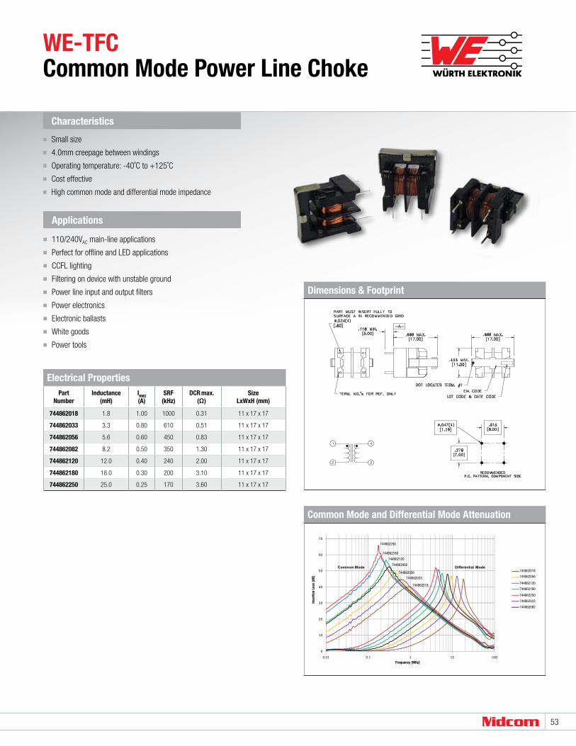
WE-TFCCommon Mode Power Line Choke
Applications
n 110/240VAC main-line applications
n Perfect for offline and LED applications
n CCFL lighting
n Filtering on device with unstable ground
n Power line input and output filters
n Power electronics
n Electronic ballasts
n White goods
n Power tools
Characteristics
n Small size
n 4.0mm creepage between windings
n Operating temperature: -40˚C to +125˚C
n Cost effective
n High common mode and differential mode impedance
Electrical PropertiesPart
NumberInductance
(mH)IRMS
(A)SRF
(kHz)DCR max.
(Ω)Size
LxWxH (mm)
744862018 1.8 1.00 1000 0.31 11 x 17 x 17
744862033 3.3 0.80 610 0.51 11 x 17 x 17
744862056 5.6 0.60 450 0.83 11 x 17 x 17
744862082 8.2 0.50 350 1.30 11 x 17 x 17
744862120 12.0 0.40 240 2.00 11 x 17 x 17
744862180 18.0 0.30 200 3.10 11 x 17 x 17
744862250 25.0 0.25 170 3.60 11 x 17 x 17
Common Mode and Differential Mode Attenuation
53

www.we-online.com
more than you expect
n Fast Time-to-Market
n Speedy Design & Sample Service
n Innovative Designs
n Logistic Solutions
n Global Account Management
n Reference Designs of Leading IC Manufacturers
n Direct Support through Solution-Oriented Employees
Added value for you. More than you expect!
INSI
GH
T D
ESIG
N 9
9994
58 •
MAR
CH 2
013
• Re
visio
n 4
Quality
Logistics
Timeto
Market
GlobalAccount
Management
DirectSupport
SpeedySampleService
InnovativeDesigns


