NASA/TM—1999–209734 Lightning Protection Guidelines for Aerospace Vehicles C.C. Goodloe Marshall Space Flight Center, Marshall Space Flight Center, Alabama May 1999 Downloaded from http://www.everyspec.com
Transcript
NASA/TM—1999–209734
Lightning Protection Guidelinesfor Aerospace VehiclesC.C. GoodloeMarshall Space Flight Center, Marshall Space Flight Center, Alabama
May 1999
National Aeronautics andSpace AdministrationAD33George C. Marshall Space Flight CenterMarshall Space Flight Center, Alabama35812
Downloaded from http://www.everyspec.com
Since its founding, NASA has been dedicated tothe advancement of aeronautics and spacescience. The NASA Scientific and TechnicalInformation (STI) Program Office plays a keypart in helping NASA maintain this importantrole.
The NASA STI Program Office is operated byLangley Research Center, the lead center forNASA’s scientific and technical information. TheNASA STI Program Office provides access to theNASA STI Database, the largest collection ofaeronautical and space science STI in the world. TheProgram Office is also NASA’s institutionalmechanism for disseminating the results of itsresearch and development activities. These resultsare published by NASA in the NASA STI ReportSeries, which includes the following report types:
• TECHNICAL PUBLICATION. Reports ofcompleted research or a major significant phaseof research that present the results of NASAprograms and include extensive data ortheoretical analysis. Includes compilations ofsignificant scientific and technical data andinformation deemed to be of continuing referencevalue. NASA’s counterpart of peer-reviewedformal professional papers but has less stringentlimitations on manuscript length and extent ofgraphic presentations.
• TECHNICAL MEMORANDUM. Scientific andtechnical findings that are preliminary or ofspecialized interest, e.g., quick release reports,working papers, and bibliographies that containminimal annotation. Does not contain extensiveanalysis.
• CONTRACTOR REPORT. Scientific andtechnical findings by NASA-sponsoredcontractors and grantees.
• CONFERENCE PUBLICATION. Collectedpapers from scientific and technical conferences,symposia, seminars, or other meetings sponsoredor cosponsored by NASA.
• SPECIAL PUBLICATION. Scientific, technical,or historical information from NASA programs,projects, and mission, often concerned withsubjects having substantial public interest.
• TECHNICAL TRANSLATION.English-language translations of foreign scientificand technical material pertinent to NASA’smission.
Specialized services that complement the STIProgram Office’s diverse offerings include creatingcustom thesauri, building customized databases,organizing and publishing research results…evenproviding videos.
For more information about the NASA STI ProgramOffice, see the following:
• Access the NASA STI Program Home Page athttp://www.sti.nasa.gov
NASA Center for AeroSpace Information National Technical Information Service7121 Standard Drive 5285 Port Royal RoadHanover, MD 21076–1320 Springfield, VA 22161(301) 621–0390 (703) 487–4650
Acknowledgments
The author acknowledges the advice and technical contributions provided during the preparation of this report by William W.Vaughan, University of Alabama in Huntsville. The review and comments of Ross Evans, Computer Sciences Corporation
(CSC), Huntsville, Alabama, are appreciated and gratefully acknowledged. The lightning photographs near launch complex39A (p. x) and in New Mexico (p. 10) were provided by NASA and Mark Brook of the New Mexico Institute of Technology.
Also, thanks to Belinda Hardin, member of technical staff (Associate) (CSC) for processing the manuscript and toMargaret Alexander for editing the draft.
Downloaded from http://www.everyspec.com
iii
PREFACE
This work was performed by the Electromagnetics and Aerospace Environments Branch,Systems Engineering Division, Systems Analysis and Integration Laboratory, Science and EngineeringDirectorate of the NASA Marshall Space Flight Center. Address questions and comments to:
Tony L. Clark Lowell E. Primm, Group LeadPhone: 256–544–2394 Phone: 256–544–9145Fax: 256–544–8029 Fax: 256–544–0242E-mail: [email protected] E-mail: [email protected]
1.1 Historical Perspective ......................................................................................................... 11.2 Requirements and Responsibilities .................................................................................... 21.3 Program Support ................................................................................................................ 4
2. Lightning protection program support plan .............................................................................. 5
3. Lightning protection process ..................................................................................................... 7
4. A New Mexico lightning display .............................................................................................. 10
5. Current test waveforms for severe direct lightning strikes ........................................................ 11
6. Current waveform composed of the four components A, B, C, and D ..................................... 12
7. Multiple-stroke lightning current test waveform consisting of a first stroke (component A)followed by 23 subsequent strokes (attenuated D components) ............................................... 12
8. Current test waveform composed of 24 bursts (a) randomly spaced within a 2-second period.(Each burst (b) consists of 20 pulses randomly spaced within a 1-millisecond period) ........... 13
9. Relationship between transient levels ....................................................................................... 22
10. Voltage attachment test waveforms ........................................................................................... 32
Downloaded from http://www.everyspec.com
vii
ABBREVIATIONS AND ACRONYMS
A ampere
ATP authority to proceed
C coulomb
CDR critical design review
DCR design certification review
DOD Department of Defense
ECP engineering change proposal
EED electroexplosive device
EME electromagnetic effects
EOM end of mission
EMP electromagnetic pulse
ETDL equipment transient design level
FAA Federal Aviation Administration
FRR flight readiness review
GSE ground support equipment
ISC short circuit current
LCIL lightning critical items list
LRU line replaceable unit
MSFC Marshall Space Flight Center
NASA National Aeronautics and Space Administration
NSTS National Space Transportation System
PDR preliminary design review
PRCB Program Requirements Control Board
PRR preliminary requirements review
RFP request for proposal
s second
SAE Society of Automotive Engineers
SIR system integration review
TCL transient control level
TPS thermal protection system
US United States
VOC open circuit voltage
Downloaded from http://www.everyspec.com
viii
LIST OF DEFINITIONS
Action integral—A critical factor in the production of lightning damage related to the energy depositedor absorbed in a system. The actual energy deposited cannot be defined without knowledge of the resis-tance of the system.
Arc attachment—The point of contact of the lightning flash with the vehicle so that current can flowonto the vehicle from this point.
Cable—Any quantity of electrical wires grouped together to form a single bundle.
Cable shield—Any metallic covering on a single (coaxial) or multiple conductor cable. The shield formmay be tinned or untinned copper braid, wrapped aluminum or copper foil tape, or rigid metal conduit.
Cable tray—Refers to standard supporting members for signal and power cable groups.
Charge transfer—The integral of the current over its entire duration, I(t)dt (coulombs).
Direct effects—Any physical damage to an element’s structure due to the direct attachment of the light-ning channel or the flow of current through the vehicle’s structures, either when the vehicle is on theground or in flight. This includes thermal and shock wave effects on the exterior skins, coatings, or otherexposed components such as windshields, nozzles, umbilical, fuel and oxidizer lines, edges, control sur-faces, and engines. Damage to electrical or avionics systems or individual equipment due to directattachment of the lightning flash to an exposed part of such a system is also termed a direct effect.
Final entry point—The spot where the lightning flash channel last “enters” the vehicle (usually a trailingedge).
Indirect effects—Voltage and/or current transients produced in vehicle electrical wiring due to lightningcurrents in the elements that can upset and/or damage components within electrical/electronic systems.These transients occur due to one or more coupling mechanisms; i.e., changing magnetic or electricfields and structural voltage rises due to lightning currents in structural resistance. Thus, voltage inducedin a sensor wire harness by changing magnetic fields accompanying lightning currents in the vehicle istermed an indirect effect. Voltages appearing in umbilical conductors due to lightning currents in umbili-cal cable shields are also called indirect effects.
Induced currents—Currents, known as capacitively coupled currents, appearing in electrical circuits dueto changing electrical fields. Also currents in complete or closed circuits driven by induced voltages inthese circuits.
Downloaded from http://www.everyspec.com
ix
Induced voltages—Voltages, known as magnetically coupled voltages, appearing in electrical circuitsdue to changing magnetic fields passing through circuits.
Initial entry point—The spot where the lightning flash channel first “enters” the vehicle (usually anextremity).
Initial exit point—The spot where the lightning flash channel first “exits” the vehicle (usually a trailingedge).
Internal environment—Includes the structural current and voltage changes with associated distributionand the aperture-coupled and diffused electromagnetic fields.
Lightning attachment points—Any spot where the lightning flash attaches to the vehicle.
Lightning flash—The total lightning event in which charge is transferred from one charge center toanother within a cloud, between clouds, or between a cloud and ground. The event can consist of one ormore strokes plus intermediate or continuing currents. Typically, the duration of a flash is 2 seconds orless.
Lightning strike—Any attachment of the lightning flash to a vehicle or ground facility.
Lightning stroke (return stroke)—A lightning current surge that occurs when the lightning leader makescontact with the ground or other region of opposite charge.
Multiple burst—A randomly spaced series of bursts of short-duration, low-amplitude current pulses andan arc pulse or pulses characterized by rapidly changing currents. These bursts may result from lightningleader progression or branching and may be accompanied by or superimposed upon a stroke or continu-ing current. The multiple bursts appear to be most intense at time of initial leader attachment to avehicle.
Multiple stroke—Two or more lightning return strokes occurring during a single lightning flash.
Subsystem—A major functional element of a system, usually consisting of several components essentialto the operational completeness of the subsystem. Subsystem examples include frame, propulsion, guid-ance, navigation, and communication. The vehicle is referred to as the overall system.
Swept “flash” (or “strike”) points—Spots where the flash channel reattaches between the initial and finalpoints, usually associated with the entry part of the flash channel.
Downloaded from http://www.everyspec.com
x
Powerful electrical storm near NASA Kennedy Space Center launch complex 39Aprior to launch of STS–8, August 30, 1983 (NASA photograph).
Downloaded from http://www.everyspec.com
1
TECHNICAL MEMORANDUM
LIGHTNING PROTECTION GUIDELINES FOR AEROSPACE VEHICLES
1. INTRODUCTION
1.1 Historical Perspective
Atmospheric electricity must be considered in the design, transportation, and operation of aero-space vehicles. Inadequately protected aerospace vehicles can be upset, damaged, or destroyed by adirect lightning stroke to the vehicle or launch support equipment before or after launch.1–3 Damage canalso result from current induced in the vehicle from changing electric fields produced by a nearbylightning stroke. The effect of the atmosphere as an insulator and conductor of high-voltage electricityat various atmospheric pressures must also be considered. Improperly designed high-voltage systemsaboard the vehicle can arc or break down at low atmospheric pressure.
The first airplane lightning protection test standards were published in the mid-1950’s by theUnited States (US) Federal Aviation Administration (FAA) and the US Department of Defense(DOD).4,5 MIL–B–5087B deals exclusively with the electrical bonding of aircraft components. Bondingrefers to a low-resistance electrical connection between components that is sufficient to withstandlightning currents. It was gen-erally believed that the damaging effects of lightning were limited to theexterior of the aircraft or to structures directly exposed to a lightning strike and sufficient protectionwould be provided if these components were adequately bonded to the main airframe.6 The FAA Advi-sory Circular 25–3 deals exclusively with the protection of aircraft fuel systems.4
In the 1960’s two spectacular incidents indicated clearly that other lightning-related effects ledto catastrophic accidents. On December 8, 1963, a lightning strike ignited fuel in the reserve tank ofa Boeing 707 commercial airliner. The left wing of the aircraft was destroyed and 81 people on boardwere killed. In 1969, Apollo 12 was launched into clouds that had been producing lightning. TheSaturn V rocket artificially triggered two discharges. The lightning strikes produced major system upsetsbut only minor permanent damage; the vehicle and crew survived and completed their mission.1 Theseaccidents motivated the FAA and the DOD to request that the Society of Automotive Engineers (SAE)Committee on Electromagnetic Compatibility (SAE–AE4) formulate improved lightning protectiondesign and test standards. The SAE report quickly became the standard for the US civil aviation indus-try.7 A revised report followed in 1978.8 This report, given a blue cover, became known as the “bluebook” and was adopted for both civil and military aircraft by the US and foreign certification agencies.The SAE-defined lightning environment was formally incorporated into military and civil protectionspecifications in MIL–STD–1757, revision MIL–STD–1757A, and FAA Advisory Circular 20–53A.9–11
Downloaded from http://www.everyspec.com
2
A panel convened in the early 1970’s to formulate lightning protection standards for the NationalAeronautics and Space Administration (NASA) Space Shuttle program. The result was “Shuttle Light-ning Protection Criteria Document,” NSTS–07636.12 The lightning environment defined in this docu-ment predated and differed somewhat from the SAE 1978 report, but key aspects of the current testwaveforms are practically the same.
Several recent trends in the design of aerospace vehicles result in an increased vulnerability tothe indirect effects of lightning. These developments include the use in the skin and structure of thevehicle of nonmetallic, lightweight composite materials that do not shield the interior of the aircraft asefficiently as a metal body and an increased reliance on digital flight control electronics as opposed toanalog and mechanical systems. If composite material is not fabricated with a metallic screen, signifi-cant structural damage could occur from spurious signals induced or coupled into the interior of thevehicle where they may damage or upset electronic processing equipment.13 A recent example of haz-ards associated with indirect lightning effects is provided by the Atlas/Centaur accident in March 1987.3
Investigation of that incident determined that the vehicle was struck by a triggered cloud-to-groundflash. The lightning current caused a transient signal to be coupled into the Centaur digital computer unitwhere data in a single memory location were changed. The computer subsequently issued an erroneousyaw command that resulted in large dynamic stresses on the vehicle and caused vehicle breakup.
Indirect lightning hazards have required additional measures in protection design philosophy.To better evaluate lightning hazards, new research programs were undertaken in the 1980’s by theNASA, U.S. Air Force, FAA, and French Government. Experimental results from these studies wereincorporated into the most recent aerospace vehicle lightning standards and guidelines.14–17
1.2 Requirements and Responsibilities
Aerospace vehicles, flight hardware, ground support equipment (GSE), and all facilities wherepotentially hazardous tests or operations are performed should be designed to withstand the lightningenvironment, as defined in section 2.2, without creating unsafe flight conditions or hazards to crew andground personnel. The vehicle should withstand this environment during vehicle prelaunch processingand flight to an altitude of 60 000 ft.
Specifically, critical structures, equipment, systems, interconnecting wiring, and cabling shouldbe analyzed for susceptibility to lightning-induced failures. Critical items identified as susceptible to theeffects of lightning should be designed to withstand the lightning environment without jeopardizing themechanical strength or function of the equipment or systems.
Downloaded from http://www.everyspec.com
3
To ensure adequate lightning protection for a specific project, the following functions should beperformed by the Lightning Protection Engineer assigned to the project:
1. Prepare, modify, and review lightning protection specifications and electromagnetic effects(EME) control plans.
2. Prepare and/or review lightning protection test plans and test reports.3. Participate in planning and performing lightning tests.4. Perform and/or review damage and upset analyses.5. Perform analyses and develop computer codes for test data scaling, circuit modeling,
and bond strap modeling.6. Support project office activities; i.e.;
a. Participate in reviews: engineering change proposals (ECP’s), waivers/deviations, etc.b. Participate in level II reviews; system integration reviews (SIR’s) and Program Require-
ments Control Board (PRCB).7. Verify completeness and accuracy of requirements.8. Prepare and/or review lightning critical items list (LCIL).9. Prepare and/or review transient control levels (TCL’s).
A typical flow for lightning protection tasks is illustrated in figure 1. The Lightning ProtectionEngineer is responsible for accomplishing all tasks, including those performed by project and/or light-ning specialty contractors.
Figure 1. Lightning protection approach.
Airframe Design
Regulations
Environment
Verification
Certification
IdentifyFlight-Critical andEssential Systems
DetermineLightningInteraction
Margins
Determine TCL’s
Determine ETDL’s
DesignProtection
Line Replaceable Unit(LRU) Section
Downloaded from http://www.everyspec.com
4
Generally, the Lightning Protection Engineer begins by developing and understanding require-ments relative to the aerospace vehicle’s mission. Questions concerning the vehicle addressed by theengineer includes: (1) Is the vehicle intended as an “all-weather” vehicle, (2) what form of lightning pro-tection will be provided at the launch site, (3) is lightning protection needed during shipping/storageand/or at test sites, and (4) what are the lightning protection problem areas inherent in the vehicledesign? With this information, lightning protection design requirements and lightning strike models ofthe vehicle are developed.
Lightning strike points are located and classified by analysis or tests. The lightning protectiondesign is then addressed for protection from direct and indirect effects of lightning. The internal andexternal effects of a lightning strike are determined, analyzed, and compared with an LCIL, TCL, andETDL to determine if the lightning protection design achieves adequate safety margins. If the lightningprotection design is deficient, there are two courses of action: (1) Redesign and correct the hardware or(2) rely on launch site protection and avoidance of weather conducive to natural or triggered lightning.
1.3 Program Support
Technical support for lightning protection design must be fully coordinated with the ProjectOffice, chief engineer, design engineers, and appropriate contractors. Coordination is important duringall phases of a program. It is particularly important to establish an effective coordination procedure toallocate the necessary manpower, facilities, and tests early in the life of a program.
1.3.1 Program Phases
NASA programs consist of the following distinct phases:
Phase A—preliminary analysisPhase B—definition and preliminary designPhase C—designPhase D—development/operation.
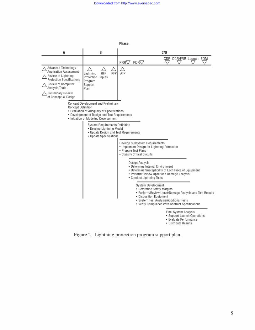
General program level information on each program phase is found in the NASA Marshall SpaceFlight Center (MSFC) Systems Engineering Handbook.17 An example of tasks and deliverables specificto lightning protection during each phase is outlined in figure 2.
Downloaded from http://www.everyspec.com
5
PRR
A B C/D
Phase
PDRCDR DCR/FRR Launch EOM
Advanced TechnologyApplication AssessmentReview of LightningProtection SpecificationsReview of ComputerAnalysis Tools
Preliminary Review of Conceptual Design
LightningProtectionProgramSupportPlan
RFPInputs
RFP ATP
Concept Development and PreliminaryConcept Definition• Evaluation of Adequacy of Specifications• Development of Design and Test Requirements• Initiation of Modeling Development
System Requirements Definition• Develop Lightning Model• Update Design and Test Requirements• Update Specifications
Develop Subsystem Requirements• Implement Design for Lightning Protection• Prepare Test Plans• Classify Critical Circuits
Design Analysis• Determine Internal Environment• Determine Susceptibility of Each Piece of Equipment• Perform/Review Upset and Damage Analysis• Conduct Lightning Tests
System Development• Determine Safety Margins• Perform/Review Upset/Damage Analysis and Test Results• Disposition Equipment• System Test Analysis/Additional Tests• Verify Compliance With Contract Specifications
Final System Analysis• Support Launch Operations• Evaluate Performance• Distribute Results
Figure 2. Lightning protection program support plan.
Downloaded from http://www.everyspec.com
6
1.3.2 Phase A—Preliminary Analysis
The first step in phase A is to determine if a lightning protection system is required, and if so,to identify the basic requirements. Once a basic set of requirements is outlined, an analysis is performedto determine if current technology meets the requirements or if advanced technology is needed. Assess-ment of the need for lightning protection during phase A is an iterative process. In addition to safety,cost and weight should be primary consideration factors in the selection of any lightning protectionsystem concept.
1.3.3 Phase B—Definition and Preliminary Design
During phase B, mission and vehicle preliminary designs are incorporated into the lightning pro-tection requirements. Special studies may be required, such as determination as to whether the vehiclestructure and covering (thermal protective system (TPS)) can withstand the direct effects of a lightningstrike. An initial estimate of internal and external effects of a lightning strike is made. Preliminary con-sideration is given to the development of a lightning protection specification, a control plan, an LCIL,and assessments of TCL’s and ETDL’s. Lightning protection requirements during this phase are usuallygeneric since the vehicle and equipment are still in the preliminary design. Figure 3 illustrates the flowprocess through phases A and B.
1.3.4 Phases C/D—Design and Development/Operations
During the design development phase, lightning strike models and lightning protection require-ments are developed or updated. As a program progresses, the baseline design for protection from directand indirect lightning effects is determined, test requirements are prepared, and tests are conducted. Ashardware becomes available, tests are conducted to verify the modeling analyses and proposed lightningprotection design.
Vehicle and payload configurations are modeled to locate the most likely entry/exit strike pointsand to compute the division of lightning current on the structure. This information determines the directeffects of lightning (burning and blasting) and indirect effects (induced cable coupling and circuit upsetor damage). An upset and damage analysis and other special analyses are performed on each lightningcritical item to established susceptibility levels. Safety margins are determined by comparing suscepti-bility levels with threat levels. Discrepancies are resolved by modifying the lightning protection designor the equipment.
When neither modification to the lightning protection design nor modification to equipment pro-vides adequate safety margins, the solution must either be reliance on the launch site and facility light-ning protection system or operations restriction when weather conductive to lightning activity is forecast.
The deliverables produced should constitute a sound system engineering approach to lightningprotection for the project. Many of the steps described may be performed by various organizations orcontractors. However, the overall responsibility to ensure that these deliverables are accurately producedis the project’s Lightning Protection Engineer.
Downloaded from http://www.everyspec.com
7
Figure 3. Lightning protection process.
Develop Lightning Protection
Requirements
LocateStrikePoints
No
Yes
Determine External Current Paths by Test and Analysis
Develop Design
Requirements
Develop Lightning
ModelExperiment
Fix
EquipmentDesign
Implement Design for Protection From Direct and Indirect
Effects
Determine Susceptibility of Each Piece of Equipment
Determine Internal Environment
(Threat Levels to Equipment)
DesignFix
Practical
WillCatenary
WireProtect?
CompareThreat LevelsWith ETDL’s
No
No
No
Yes Yes
Yes
*6-dB Electronics20-dB Ordinance
Restrict Operation When Lightning is
Forecast
Lightning Protection Adequate
Safety Margin*Exists
Downloaded from http://www.everyspec.com
8
2. LIGHTNING—COMPLEX ELECTRICITY
2.1 Overview
Lightning is a secondary effect of electrification within a thunderstorm cloud system. It is a giantelectrical spark that can have a peak current flow >200 000 A during a period of a few microseconds.
Thunder results from the sudden heating of the air to ≈20 000 K by the flow of current along anarrow channel. This flow of current can be from cloud to ground as several individual strokes separatedby a tenth of a second, or it can be from cloud to cloud in strokes that are not readily visible from theground but which diffusely illuminate the cloud. It can also be from cloud through an aircraft or aero-space vehicle operating in the vicinity. About 1 800 thunderstorms are active over the Earth’s surface atany given time. Lightning strikes the Earth ≈100 times per second.
On a cloudless day, the potential electrical gradient in the atmosphere near the surface of theEarth is relatively low (<300 V/m); but when clouds develop, the potential gradient near the surface ofthe Earth increases. If the clouds become large enough to have water droplets of sufficient size to pro-duce rain, the atmosphere potential gradient may be sufficient to result in a lightning discharge withmeasured gradients >10 000 V/m at the surface.
A variety of charge separation processes occurs at the microphysical and cloud-size scales.18
These processes vary in importance, depending on the developmental stage of convective clouds. How-ever, it has been suggested that both induction and interface charging are the primary electrificationmechanisms in convective clouds.19 Inductive charging involves bouncing collisions between particlesin the external field. The amount of charge transferred between the polarized drops at the moment ofcollision depends on the time of contact, contact angle (no charge transferred at grazing collisions),charge realization time, and net charge on the particles. Interface charging involves the transfer ofcharge due to contact or freezing potentials during the collisions between riming precipitation particlesand ice crystals. The size and magnitude of the charge transfer depend on the temperature, liquid watercontent, and ice crystal size and impact velocity.
Gradients may be considerably higher at altitudes than those just above the surface. The Earth-ionospheric system can be considered as a large capacitor with the Earth’s surface as the negativelycharged plate, the ionosphere as the positively charged plate, and the atmosphere as the dielectric.
When a cloud develops into the cumulonimbus state, lightning discharges result. For a dischargeto occur, the potential gradient at a location reaches a value equal to the critical breakdown value of airat that location. Laboratory data indicate this value is as high as 1M V/m at standard sea level atmos-pheric pressure. Electrical fields measured at the surface of the Earth are much lower than 1M V/mduring lightning discharges. There are several reasons why:
Downloaded from http://www.everyspec.com
9
1. Most clouds have centers of both polarities that tend to neutralize values measured at thesurface.
2. Each charge in the atmosphere and its image within the Earth resemble an electrical dipole,and the intensity of the electrical field decreases with the cube of the distance from thedipole.
3. The atmospheric electric field measured over land at the surface is limited by dischargecurrents arising from grounded points, such as grass, trees, and other structures, which ionizethe air around the points, thus producing screen space charges.
When lightning strikes a protected or unprotected object, such as an aerospace vehicle on alaunch pad, the current flows through a path to the true Earth ground. The voltage drop along this pathmay be great enough over a short distance to be dangerous to people and equipment. Cattle and humanshave been electrocuted from the current flow through the ground and the voltage potential between theirfeet while standing under a tree struck by lightning.
A static charge may accumulate on an object such as an aerospace vehicle from its motionthrough an atmosphere containing raindrops, ice particles, or dust. A stationary object, if not grounded,can also accumulate a charge from windborne particles (often as nuclei too small to be visible), or rain,or snow particles striking the object. This charge can build up until the local electric field at the pointof sharpest curvature exceeds the breakdown field and, thus, triggers a lightning discharge. The quan-tity of maximum charge depends on the size and shape of the object (especially if sharp points are on thestructure).
If a charge builds up on a structure that is not grounded, any discharges that occur could igniteexplosive gases or fuels, interfere with radio communications or telemetry, or cause severe shocks topeople. Static electrical charges occur more frequently during periods of low humidity and can be expec-ted at any geographical area.
2.2 Lightning Environment
The waveforms defined in this section are idealized representations of severe lightning flashesand constitute the lightning environment that the aerospace vehicle must withstand when it is exposedon the ground to lightning and during each phase of atmospheric flight (see fig. 4 for a lightningdisplay). This environment represents both naturally occurring and triggered lightning strikes.
The waveforms constitute an industrywide standard for lightning protection design as the funda-mental basis for analyses and, where practical, for verification tests. It is recognized that testing labora-tories may not be capable of generating these idealized waveforms. The issue of waveforms suitable fortests is addressed further in section 4. Results from test waveforms that deviate from the idealizedwaveforms should, therefore, be capable of being related to the waveforms discussed in this report.
Downloaded from http://www.everyspec.com
10
The currents in a lightning flash are conveniently separated into three categories:
1. Return stroke surges with peak currents up to 200 000 A or more and duration on the orderof tens of microseconds.
2. Intermediate currents up to 10 000 A or more and duration on the order of milliseconds.
3. Continuing currents up to 1 000 A and duration on the order of hundreds of milliseconds.
Intermediate and continuing currents are primarily responsible for damage such as hole burning,while return stroke currents mainly produce explosive and indirect effects.
Currents are also associated with subsequent return strokes. Phases of the return strokes are char-acterized by rapid rates of change. These categories, represented by idealized waveforms designated A,B, C, D, and H, are described in the following paragraphs. In mathematical definitions, the various con-stants are given to multidigit precision, intended only for mathematical consistency. It is not implied thatthe physical characteristics of lightning are known to such accuracy or that analyses and tests need toreflect such extreme accuracy and precision.
Five current component waveforms which represent a severe lightning strike event are specifiedin the SAE 1997 Report AE4L–97–4, the industry standard for transport aircraft.15 AE4L–97–4 testspecifications were also incorporated into a recent revision of the NASA “Lightning Protection CriteriaDocument.”14 AE4L–97–4 current waveforms are illustrated in figures 5 through 8.
Figure 4. A New Mexico lightning display.
Downloaded from http://www.everyspec.com
11
Peak Current200 kA
Time to Peak6.3 µs
Time to 90%3.0 µs
Time to 90%1.497 µs
Time to 10%0.151 µs
Time to 10%0.078 µs
Rate of Rise1×1011 A/s @ 0.5 µs
Rate of Rise1×1011 A/s @ 0.25 ms
200 kA
Time to Peak3.179 µs
100 kA
Current Transfer10 C
Average Current2 000 A
Average Current2 000 A
Decay to 50%68.97 µs
Action Integral2×106 A2s
Peak Current100 kA
Decay to 50%34.48 µs
Action Integral0.25×106 A2s
500 µsto ~0
Waveform
500 msWaveform
≤500 µsWaveform
Component C Component D
Max Rate of Rise1.4×1011 A/s
Wavefront
5 msWaveform
Component A
Total Charge Transfer200 C
Component B
Max Rate of Rise1.4×1011 A/sWavefront
Figure 5. Current test waveforms for severe direct lightning strikes.
Downloaded from http://www.everyspec.com
12
200 kA
50 kA
A D/2 D/2 D/2 D/21 2 3 23 24
10 ms ≤ ∆t ≤ 200 ms
2 s
Figure 7. Multiple-stroke lightning current test waveform consisting of a first stroke (component A)followed by 23 subsequent strokes (attenuated D components).
Figure 6. Current waveform composed of the four components A, B, C, and D.
A B C D
Curr
ent (
not t
o sc
ale)
Component A (Initial Stroke)Peak Amplitude = 200 kA±10%Action Integral = 2×10⁶ A2s±20%Time Duration ≤500 µs
Component C (Continuing Current)Charge Transfer = 200 C±20%Amplitude = 200 to 800 ATime Duration 0.25<T≤1 s
Component B (Intermediate Current)Maximum Charge Transfer = 10 CAverage Amplitude = 2 kA±10%Duration ≤5 ms
Component D (Restrike)Peak Amplitude = 100 kA±10%Action Integral = 0.25×10⁶ A2s±10%Duration ≤5 µs
Downloaded from http://www.everyspec.com
13
2.2.1 Compound A
This waveform represents a first return stroke with a peak current of 200 000 A and is definedmathematically by:
I(t) = IO (e –at –e –bt) (1)
where
IO = 218 810 Aa = 11 345 s–1
b = 647 265 s–1
t = time (s).
This waveform component has a very large peak current, peak current derivative, and actionintegral.
2.2.2 Component B
This component represents an intermediate current following the first return stroke. ComponentB has an average amplitude of 2 000 A and transfers 10 C of charge. This component is described bya double exponential of the form shown in equation (1) where IO = 11 300 A, a = 700 s –1,b = 2 000 s–1, and t = time (s).
1 2 24
1 ms
10 ms ≤ ∆t ≤ 200 ms10 kA
10 kA
1 2 3 20
10 µs ≤ ∆t ≤ 50 µs
Figure 8. Current test waveform composed of 24 bursts (a) randomly spaced within a 2-second period.(Each burst (b) consist of 20 pulses randomly spaced within a 1-millisecond period.)
(a)
(b)
Downloaded from http://www.everyspec.com
14
2.2.3 Component C
This waveform represents a continuing current. Component C is a square waveform with a cur-rent amplitude between 200 and 800 A and a duration of 1.0 to 0.25 s, chosen to give a total chargetransfer of 200 C. The primary purpose of this waveform is charge transfer.
2.2.4 Component D
Component D represents a subsequent stroke with a peak current of 100 000 A. This componentis described by a double exponential of the form shown in equation (1) with IO = 109 405 A,a = 22 708 s –1, and b = 1 294 530 s –1.
2.2.5 Component H
Component H is a short-duration, high rate of rise current pulse with a peak current amplitudeof 10 000 A. This test waveform incorporates important characteristic lightning discharges recordedduring trigger strikes to instrumented aircraft in flight. This waveform is also defined by a double expo-nential where IO = 10 752 A, a = 187 191 s –1, and b = 19 105 s –1. Component H has a peak currentderivative of 2×10¹¹ A/s.
Figure 6 depicts and characterizes the key aspects of a current waveform consisting of the sumof components A, B, C, and D. The test values, a peak current of 200 000 A, a charge transfer of 200 C,and an action integral of 2×10⁶ A2 s, occur at the 1-percent level or less in negative ground discharges(at least 99 percent of the lightning strikes will be lesser in magnitude). Approximately 10 percent ofpositive ground discharges, however, while generally more infrequent, are expected to exceed these testsvalues. The peak current derivative test value, 1.4×10¹¹ A/s, probably does not represent a severe leveltest.
Ten percent of the return strokes triggered in Florida during 1987 and 1988 had current deriva-tives which exceeded 215 000 A/µs.20 A maximum peak di/dt value of 411 000 A/µs has been measuredin Florida. A stroke current of ≈60 000 A, with di/dt value of 380 000 A/µs was recorded during mea-surements conducted with the NASA F–106 aircraft.
A typical flash consists of a first return stroke followed by several subsequent strokes. For pro-tection against direct effects, it is adequate to consider only one return stroke (component A or D). Fora proper evaluation of indirect effects, such as coupling into the interior of an aerospace vehicle, it isnecessary to consider the multiple-stroke nature of an actual flash. For this purpose, a multiple strokeconsisting of a component A current pulse followed by 23 randomly spaced subsequent strokes of50 000 A peak amplitude (component D divided by 2), all occurring within 2 s, has been defined.The multistroke test waveform is illustrated in figure 7.
Downloaded from http://www.everyspec.com
15
Rapid sequences of pulses with low-peak current amplitude, but large current derivative values,were observed during the lightning strike measurements made with instrumented aircraft. While a singlecurrent pulse, like component H, is not likely to cause physical damage, a burst of randomly distributedpulses may cause interference or upset in some systems. A test standard, consisting of component H cur-rent pulses occurring repetitively in a 2-second period in 24 randomly spaced groups of 20 pulses each,has been defined. This multiple burst waveform is illustrated in figure 8.
The idealized waveforms described above are appropriate for design analyses. The cost of con-structing a simulator capable of delivering these test waveforms to actual vehicles may be prohibitive.In that case, actual testing may involve the use of different waveforms. It must be possible, however,to extrapolate or scale the test results made with the alternate waveforms to the severe hazard leveldescribed above.
Downloaded from http://www.everyspec.com
16
3. LIGHTNING PROTECTION REQUIREMENTS
Several lightning current parameters are important in assessing the potential for lightningdamage; i.e., peak current (I), the peak current derivative (di/dt), the charge transfer (Q—the integralof current over time), and the action integral (the integral of the square of the current over time, ∫ i2 di.
For objects having primarily a resistive impedance, the peak voltage that develops across theobject will depend on the peak current. A large voltage that develops at one end or across an object maylead to discharges through the air and around the object (creating a short circuit) from the object toground.
For objects and systems consisting primarily of an inductive impedance, such as cabling in elec-tronics systems or electrical connections on printed circuit cards, the peak voltage is proportional to thetime derivative of the current. For example, if a current with a peak di/dt of 1 000 A/µs (one hundredthof a typical lightning peak di/dt value) is injected into a straight length of wire with an inductance of1 µH/m, a voltage of 1 000 V will develop across 1 m of the wire. It is easy to imagine the damage thisproduces in solid state electronic systems that are sensitive to transient voltages in the tens-of-voltsrange.
The heating or burn through of metal sheets such as airplane wings or metal roofs is, to a crudeapproximation, proportional to the charge transferred during a lightning strike. Generally, large chargetransfers occur during the long-duration, low-current amplitude portions of lightning discharges such asthe continuing current phase, rather than during the short-duration, high-current amplitude return strokeprocesses.
The heating of electrically conducting materials and the explosion of nonconducting objects are,to a first approximation, determined by the value of the action integral since the quantity ∫ i2 Rdi is theJoule heating (R is the resistive impedance). Generally, electrical heating vaporizes internal material andthe resulting increase in pressure causes a fracture or explosion to occur.21
3.1 Flight Hardware
A determination should be made as to which systems and components on or within each elementof the aerospace vehicle are lightning critical. Protection should be incorporated into each of theseitems.22
3.1.1 Direct Effects
Protection should be provided against the direct effects of lightning to surfaces, structures,components, and joints exposed to direct arc attachment and current conduction. Protective measuresinclude the following:
Downloaded from http://www.everyspec.com
17
1. Electrical cables should not be exposed to the direct effects of lightning. When unavoidable,exposed cables should be covered by conductive enclosures of proper mechanical strengthand thickness with appropriate electrical continuity.
2. Vehicle structural interfaces between elements of the aerospace vehicle should be capableof conducting the applicable portion of the lightning current without detrimental effects onthe structure and electrical, pyrotechnic, or propellant subsystems.
3. Suitable, nondetrimental conductive current paths (lightning bonds) should be providedbetween structures, components, joints, and extremities to conduct, attenuate, or redirect theapplicable portion of the lightning currents and voltages. Attainment of a specific electricalresistance should not, solely, be taken as evidence that structures, components, and joints cansafely carry lightning currents. Section 4 discusses the criteria for lightning bonds.
4. Lines, containers/tanks, drains, and vents should be designed to ensure that the ignition pointof the materials (flammable fluids, gases, and solids) contained by or transferred throughthem should not be reached due to any effects of a lightning flash.
3.1.2 Indirect Effects
Protection from the indirect effects of lightning should be provided to ensure that all lightningcritical systems, equipment, components, and propellants tolerate the lightning-induced voltages andcurrents appearing at their interfaces. Protective measures include the following:
1. The internal environment, which arises as a result of direct strike to the vehicle, should bedetermined. Induced voltages and currents resulting from the internal environment must alsobe determined. Methods for determining the internal environment and induced voltages andcurrents are provided in section 4.
2. All cables and/or wires should have an overall shield for lightning protection, unless protec-tion is provided by other means. The overall shield, as a minimum, should be grounded tobulkhead metallic structure or equipment grounding terminals at each end. Intermediategrounding should be used where the overall shield penetrates or touches metal. Overall cableshields should have a minimum optical coverage of 85 percent. Termination of overallshields should be made along a 360-degree periphery of the bulkhead feedthrough connectorshell. The feedthrough connector should be grounded in a 360-degree manner to the surfaceupon which it is mounted. Terminating and grounding overall shields at such surfaces withpigtails or single pins are not acceptable design. All wiring interfaces should be protected inorder to eliminate or minimize effects due to lightning-induced voltages and/or currents.
3. Apertures, which allow detrimental lightning-generated electromagnetic fields to penetratethe vehicle structure, should have metallic screens to prevent these fields from inducinghazardous indirect effects.
Downloaded from http://www.everyspec.com
18
3.2 Ground Support Equipment and Facilities
3.2.1 Direct Effects
Protection should be provided against direct effects of lightning on equipment and/or facilitiesexposed to direct arc attachment and current conduction.22 Electrical continuity to Earth as the groundshould be maintained between launch vehicle and integrating support facilities during all phases ofground operations.
Suitable, nondetrimental current paths (lightning bonds) should be provided between equipmentand/or facilities to conduct, attenuate, or redirect the applicable portion of lightning currents and volt-ages. Attainment of a specific electrical resistance shall not, solely, be considered evidence that struc-tures, components, and joints can safely carry lightning currents. The criteria for lightning bonds arediscussed in section 4.
3.2.2 Indirect Effects
Protection from the indirect effects of lightning should be provided to ensure that all equipmentand/or facilities tolerate the induced voltages and currents at their interfaces.
3.2.3 Vehicle-to-Facilities Interfaces
All metallic penetrations of the vehicle skin should be electrically bonded to the vehicle skin. Ifbonding is accomplished with a jumper, this jumper should be as short as possible.
Wiring interfaces should be designed to prevent voltage or current resulting from the direct orindirect effects of lightning from damaging or interfering with equipment. Ground hardware electricallines should interface with the vehicle as close to the base of the vehicle as practical to minimize theindirect effects of lightning.
3.3 Pyrotechnics
3.3.1 Protection of Materials and Devices
A specific current path around pyrotechnic materials and devices should be designed so thateffects of the lightning environment do not cause either the inability to fire or inadvertent firings.22
Downloaded from http://www.everyspec.com
19
3.3.2 Protection of Electrical Systems
Pyrotechnic electrical firing circuits, power sources, and controlling logic should be designed sothat no failures will result from the direct and indirect effects of lightning currents.
All enclosures that contain pyrotechnic devices or components should be electrically bonded tothe vehicle structure. An overall shield should be provided for each electroexplosive device (EED) firingcircuit cable. Separate twisted pair wires should be provided within each cable. Shields should be con-tinuous without breaks or splices, with exception of through pins in pressure bulkhead electrical con-nectors. Shields should be terminated at connectors using 360-degree coverage. The shield designshould provide a minimum optical coverage of 85 percent.
Downloaded from http://www.everyspec.com
20
4. BASIC STEPS IN DESIGNING TO WITHSTAND LIGHTNING
Lightning protection is incorporated in the aerospace vehicle most effectively and economicallyif designed by the steps listed below.22 These steps provide a methodology that has been proven to workon prior aerospace vehicle projects.
4.1 Lightning Critical Systems
Identify the systems and/or components which may be affected by lightning and whose properoperation is critical or essential to the vehicle. These items make up the LCIL. The LCIL hardware isanalyzed to ensure that each item can withstand the lightning environment. In some areas, it is obviousthat a system is either susceptible or not affected. Identify the level of voltage and current each systemand item should be designed to accommodate. In areas where questions remain after appropriate analy-sis, the system or subsystem must be tested.
Identify systems and components vulnerable to interference or damage by lightning from eitherdirect effects (physical damage) or indirect effects (electromagnetic coupling). To some extent, lightningstrikes affect nearly the entire vehicle and the systems located within. In many cases, the effects areminor and of no consequence to flight safety. However, in order to be certain, each system or subsystemsusceptible to lightning or potentially vulnerable to its effects should be reviewed during the lightningprotection process.
4.2 Lightning Strike Zones
Location of lightning strike zones on an aerospace vehicle depends on geometry, structuralmaterial, and operational factors such as flight altitude and velocity.
Characteristics of currents entering the aerospace vehicle may vary according to locationon the vehicle. To account for these variations, lightning strike zones are defined as follows:
Zone 1A—Initial attachment point with low possibility of lightning channel hang-on.
Zone 1B—Initial attachment point with high possibility of lightning channel hang-on. (All components of a long-duration continuing current are realized in this zone.)
Zone 2A—A swept stroke zone with low possibility of lightning channel hang-on.
Zone 2B—A swept stroke zone with high possibility of lightning channel hang-on.(No initial stroke, but a long-duration continuing current is realized in this zone.)
Downloaded from http://www.everyspec.com
21
Zone 3—Those portions of the airframe that lie within or between the other zones which maycarry substantial amounts of electrical current by conduction between areas of direct or sweptstroke attachment points. Zone 3 includes those surfaces where attachment of the lightningchannel is a very low possibility.
4.3 Direct Effects Protection
Provide protection against the direct effects of lightning to surfaces, structure, components, andjoints exposed to direct arc attachment and conduction. Electrical cables should not be exposed to directeffects of lightning. When exposure is unavoidable, cover cables with a conductive enclosure of propermechanical strength and thickness to protect against the lightning environment.
4.3.1 External Lightning Environment
Identify the components of the total lightning flash current expected in each lightning strikezone. These are currents against which the vehicle must be protected. Lightning flashes are subdividedinto components and important characteristics are described. Hardware is analyzed for direct and indi-rect susceptibility to each lightning flash component described in section 2.2.
In evaluating direct effects, the most significant parameters are peak current, action integral,charge transfer, and duration. Tests to evaluate direct effects on structural components must be per-formed at full threat. It is feasible to generate full threat currents with the required combination of theseparameters.
The full threat model lightning flash for direct effects test is defined in reference 14. It has fourcomponents corresponding to the four components of the model lightning flash defined for purposes ofanalysis. Each component (A, B, C, and D) simulates a different characteristic of the current in a naturallightning flash. The waveforms are shown in figure 4. The waveform selected for a particular test oranalysis depends on the classification of vehicle strike zones and whether direct or indirect effects are tobe evaluated.
4.4 Indirect Effects Protection
The protection design is determined by demonstrating that (1) the maximum induced transientsappearing at the equipment/harness interfaces are less than the established TCL and (2) the equipmentcan tolerate the ETDL at input terminals. Appropriate margins must be maintained. Verification isaccomplished by test, analysis, or similarity to other systems and/or equipment or combinations of thesemethods.
4.4.1 Internal Environment
The internal environment is the environment created as a result of a direct strike to the vehicleand is associated with the vehicle’s internal E and H fields.
Electromagnetic fields appear in the interior of any element of the vehicle by aperture couplingor diffusion. Voltages and currents induced by these fields constitute the internal environment.
Downloaded from http://www.everyspec.com
22
The magnitude of these internal fields, determined by shielding effectiveness of the vehicle, maydamage electrical/electronic equipment. The fields and structural potentials (current × resistance (IR))produce voltages and currents on interconnecting wiring at equipment enclosures and, thus, compromisesystem operation.
4.4.2 Induced Voltage/Current Levels
For each lightning critical system, the induced voltage and current appearing at electrical/electronic equipment interfaces are determined. In most cases, these are defined in terms of the opencircuit voltage (Voc) and short circuit current (Isc) developed at the wiring/equipment interfaces. The Vocand Isc are related by the source impedances of interconnecting wiring. Different levels may be deter-mined for different circuit functions or operating voltages. These levels are determined by analysis ortest and are defined on pp. 467 and 481 of Lightning Protection of Aircraft.23
4.4.3 Transient Control Levels/Equipment Transient Design Levels
Establishing system TCL’s and ETDL’s is the best method of specifying indirect effects protec-tion requirements. The TCL’s are the actual environment (i.e., pin injection voltage) that the equipmentexperiences during a lightning strike. This environment is the result of the internal lightning-inducedenvironment after application of system-level equipment shielding and transient suppression (i.e., filtersor Transzorbs) effects.
The ETDL is the environment (i.e., pin injection voltage) that the equipment should be designedto withstand. For equipment to survive a lightning encounter, the ETDL must be greater than the TCL.The difference between ETDL and TCL is the design margin. A positive design margin indicates suc-cessful hardening of the system.
The relationship between transient control and equipment transient design and susceptibilitylevels is illustrated in figure 9. The TCL and ETDL are established by the system integrator whoassesses the impact of shielding cables versus hardening equipment to establish the most efficient levels.
Equipment Transient Susceptibility Levels
ETDL
Margin
TCLActual Transient
Levels
InterconnectingWiring
Electrical/ElectronicEquipment
Figure 9. Relationship between transient levels.
Downloaded from http://www.everyspec.com
23
4.5 Lightning Protection Measures
Twelve lightning protection design measures should be considered for each system and/or com-ponent needing protection. Use of these design measures helps carry the lightning current on the outsideof the vehicle and minimizes apertures and joints where fields can enter, thus keeping equipment andcables away from higher fields. The design measures are as follows:
4.6 Successful Lightning Protection Design and Certification
Numerous considerations are important throughout the design and certification process for anaerospace vehicle.
4.6.1 Begin the Process Very Early in the Design Stage
The basic fabricated materials of an aerospace vehicle contribute significantly to the effects oflightning strikes and to the interactions that lightning currents and associated electromagnetic fields havewith onboard systems. Composite materials are often vulnerable to lightning damage and require pro-tection. Current protection methods often become an integral part of skins and structures. Decisions onwhat protection approach to take should be made early and coordinated with other structural require-ments. Frequently, developing design details takes time, so the overall approach needs to be establishedvery early to avoid expensive retrofit.
4.6.2 Locate Lightning Strike Zones Early in the Design Phase
Lightning strike zone locations depend on vehicle geometry and the expected operational enve-lope. Since these zones define specific lightning environments, it is imperative that zones are locatedand understood as early as possible to avoid later controversies and misunderstandings.
Downloaded from http://www.everyspec.com
24
4.6.3 Test During Development Phases
In the past it was often possible to successfully complete a lightning protection design and per-form a verification test on the finished article. Due to the complex electrical and mechanical nature ofmany current vehicle designs, there is a very high risk of failure in this approach. Instead, it is prudent toperform lightning current transfer tests (for example) on candidate structural joints and other ele-ments,as well as critical components of other systems, at an early date. Such tests are usually referred to as“developmental tests” or “engineering tests” and are performed on small structural coupons or indi-vidual pieces of a complete system. They provide data for design selection and minimize the risk offailure during a complete systems test later in the program.
Because some structures and systems cannot be lightning tested as a whole due to size or com-plexity, developmental testing must be relied on to support design verification and certification. In suchcases, verification must usually be shown by analysis. Analysis shows how developmental test resultsare combined to demonstrate design adequacy and/or compliance with specifications. For this to bedone, developmental test specimens, procedures, and results should be carefully documented whenconducted.
4.7 Electromagnetic Effects Control Plan
Some combination of analysis, similarity with previous designs, developmental testing, andqualification testing is required to ensure adequate lightning protection for the vehicle. To ensure that allflight-critical elements of the design are verified and to avoid costly and unnecessary testing, an EMEcontrol plan should be prepared. This is particularly important for new and “untried” advanced launchvehicle designs which usually involve high authority electrical/electronic systems. The control plan neednot be a lengthy document describing detailed test or analysis procedures. It should present in brief andconcise terms descriptions of the roles of developmental testing, analysis, qualification testing, etc.
4.8 Pass-Fail Criterion
Lightning currents of the magnitude defined in present test standards nearly always inflict somedamage to the element’s structure. Sometimes this damage results only in superficial discoloration of apart. In other cases it may result in pinching or deformation of aluminum parts or puncture and delam-ination of composites. Often these effects do not comprise a hazard to flight safety, but it must be dem-onstrated that this is the case. Unfortunately, the nature of the damage cannot always be predicted inadvance of a lightning test, so the “pass-fail” requirement is established after the test is completed. Thismay involve aerodynamic and structural analyses of the damaged parts before a decision is made.
Downloaded from http://www.everyspec.com
25
5. PROTECTION DESIGN VERIFICATION
Verify adequacy of the lightning protection designs by similarity with previously proven installa-tion designs, simulated lightning tests, or acceptable analysis. When analysis is utilized, appropriatemargins to account for uncertainties in the analytical techniques may be required. Use developmentaltest data for certification when properly documented and coordinated with the Lightning ProtectionEngineer. This section discusses specific analyses and test details to verify protection adequacy.22
5.1 Analysis Techniques
External direct effects and internal E and H fields that appear inside the vehicle skins are asso-ciated with a strike to the aerospace vehicle system. The magnitude of the internal fields is determinedby the shielding effectiveness of the vehicle and the properties of the lightning strike. These internalfields may cause damage to the electrical/electronic equipment or introduce signals which may upsetoperation of the equipment. To adequately perform verification of the equipment, an understanding ofthe external and internal environments and interactions is required.
5.1.1 Direct Effects Analysis Verification Techniques
Direct effects are physical damage at the points of attachment, at the point of exit, and anyinterstructural current-carrying effects.
5.1.2 Electrical Bonding
Providing an aerospace vehicle a suitable, nondetrimental path for lightning-produced currentsand voltages is an important part of lightning protection. To provide this protection, each interface mustbe considered separately. An interface is any place two pieces, parts, or components join together. Thisincludes interfaces from the manufacturing process and from adding bond straps to existing structure.
Each interface must be designed for the vehicle, recognizing that the lightning event is domina-ted by time-varying currents. This is the reason lightning current paths are governed much more byinductance rather than resistance. The voltage rise due to inductance is a function of the rate of change.Even on paths in which the amplitude is reduced by current division, the inductive voltage rise can besevere. For example, if the current rate of rise is 1×10¹¹ A/s and the inductance is 1 µH/m, 100 000 Vappear across each meter of the path. Experience shows that achieving a direct current resistance of2.5 mΩ has little significance to adequate lightning protection.
The criteria to assess the adequacy of lightning protection (bonding) at each interface is morethan the direct current resistance of the interface. Detrimental arcing and sparking at an interface aremore functions of area current density and strength of dielectric insulation than direct current resistance.
Downloaded from http://www.everyspec.com
26
Additional assessment criteria include the following:
1. Specific descriptions of materials contacting the interface (corrosion can degrade the bondover time).
2. Specific descriptions of the surface contact area and surface treatments.
3. Specification of the compression of joints and fasteners (pounds per square inchor foot-pounds of torque).
4. Specification of path dimension sufficient to determine inductance as well as directcurrent resistance.
5. Specification of the lightning strike zone or zones within which each interface falls.
Use of a resistance measurement alone does not verify a good lightning bonding. But resistancemeasurements can be used for manufacturing and quality control.
5.1.3 Indirect Effects Analysis Techniques
The upset or damage generated by lightning-induced voltages and currents are indirect effects.
Internal electric and magnetic field environments must be estimated. The highest E fields existjust prior to and during the attachment process of the lightning strike. The voltage between the chargecenter and the vehicle must reach the point at which the air gap breaks down (typically fields of500 000 V/m). Until breakdown occurs and the leader is complete from the cloud to Earth (or the oppo-site charge center), the current levels are low and magnetic fields are low. Once the leader is complete,the return current begins creating significant magnetic fields.
Electric fields are in the lightning strike, but levels are generally quite low (10 to 100 V/m).Magnetic fields associated with the lightning strike are most intense at the outside surface of the vehicle.Internal magnetic fields depend on the shielding afforded by the vehicle structure and the geometry ofthe vehicle between attachment points. Magnetic fields on the outside of the vehicle skin enter the inter-ior by leakage through apertures and diffusion through the skin itself. Holes in the conductive structure,windows, and seams or joints are the apertures through which the magnetic flux can leak into the interiorof the vehicle. Internal magnetic fields are highest near these apertures.
Internal-induced voltage and current environment must also be estimated. Before flight hardwareexists, analysis is the only tool available to provide estimates of the induced voltages and currents thatcan enter/exit the wiring. Estimates are required of magnetic field levels in different regions of the sys-tems. These estimates are based on the magnetic field intensities at the surface next to the apertures,which are then extrapolated internally. These field levels are the representative conservative levelsassociated with a severe strike attaching near the region of interest. If use of these field levels results inprotection requirements that severely impact design, cost, and weight, further analysis or test to refinethe threat must be made.
Downloaded from http://www.everyspec.com
27
To calculate the open circuit common mode voltage of a wire,
Voc = µo AdH/dt (2)
where
A = loop area in square metersµo = 4×10⁻⁷ H/m (permeability of free space)H = magnetic field in A/mt = time (s).
It must be emphasized that the voltage calculated is between the wire and the structure. Since thedifferential voltage is the result of variations in terminations, it is not possible to accurately predict thevalue from the circuit parameters. In practice, the differential voltage is less than the common mode bya factor of 10 to 100. The wire or cable short-circuit current is calculated from the open circuit voltage,and the cable self-inductance is estimated as follows:
Isc = 1/L Voc dt (3)
where
L = self-inductance of the cable in H/mVoc = open circuit voltaget = time (s).
Cable inductance is estimated:
L = 2×10⁻⁷ ln (h/d) (4)
where
d = conductor diameterh = height above structure.
Note: The induced voltage, Voc, which drives the current is proportional to the cable height, butthe cable inductance which resists the current is proportional to the logarithm of height.
In some cases, the circuits of concern are superimposed on the AC and DC bus voltages, Vbus.Since the power buses are quite extensive, they experience inducted voltages of their own.
In addition to the magnetic-coupled voltage, structural voltages, Vs also appear. For the worstcase, it must be assumed that the power bus voltage is added to the signal line-induced voltage. In thosecases, the total induced voltage is
Vt = Vbus + Vs + Voc (5)
Downloaded from http://www.everyspec.com
28
where
Vt = total voltageVbus = power bus voltageVs = structure voltagesVoc = open circuit voltage.
If a circuit routes through several sensors or several pieces of equipment, the voltage from eachsection must be added.
Two major areas, upset and transient damage (failure) analysis, must be addressed whenverifying lightning protection for complex digital systems that utilize solid state electronic devices.
Upset must be assessed with statistical methodologies. Upset usually occurs when voltage andcurrent levels are below device failure levels. Upset may affect input data lines, devices, or any com-bination of these. Because the effects of upset occur randomly with time, upset is a stochastic phenom-enon. Redundancy is no protection against upset due to lightning. Lightning can affect all redundantsystems identically and simultaneously.
Transient damage (failure) analysis relates to the maximum power levels, which may appear atthe input/output solid state devices. This analysis provides the maximum levels of voltage and current agiven interface can withstand. If it is shown that actual transient levels are equal to or exceed theselevels, then steps must be taken to reduce these levels to acceptable values.
Lightning strike to a vehicle causes open circuit voltage and short circuit current to be inducedon wire cables. These voltages and currents could couple into electrical equipment and cause a criticallogic upset. If the upset generates erroneous input/output states, it could produce a risk of vehicle loss.
Two independent methods determine if an electronic element could enter a critical logic upset.The first method seeks equipment containing memory devices capable of changing state within100 µs. The second determines if the equipment has the authority to influence the system and, if upset,produce a risk to the system.
The first upset analysis technique uses an “assumed upset” method of identifying the LCILelements that respond in <100 µs and maintain this changed state. These memory elements, due to theirfast response time, are referred to as low inertia memories. It is then assumed that each low inertiamemory is upset and the effect of an upset upon the system is determined.
Give careful consideration to the ability of the equipment to recover or reset before it contributessignificantly to data or logic pollution. If a recovery method exists for upset equipment, what is the max-imum elapsed time for the recovery? Does recovery rely on external (automatic or procedural) inputs orself-recovery? Do override controls exist? Are there cues, talkbacks, or warnings during recovery? Canrecovery be assured before the upset causes risk to the vehicle?
Downloaded from http://www.everyspec.com
29
Under this analysis technique, flight-critical, active-on-ascent equipment has low inertia memo-ries, which could cause risk to vehicle mission success or have no significant acceptable recovery orreset method, both of which are considered mission critical.
The second upset analysis technique involves determining if the equipment has independentauthority to control its output. If a sensor’s input data are used to make the decision whether or not anevent actually occurred, this decision must be made using multiple samples of the sensor to say thesystem is immune to logic upset of the subject sensor.
Declare the vehicle immune to the logic upset of a multiple mode whole value sensor if thefollowing conditions are true:
1. The correct sensor mode can be reestablished following the logic upset event before thesensor’s performance or the system’s performance is impacted because of a lack of criticalsensor data.
2. If the sensor mode can be reestablished in time, the sensor data processing must beperformed in the same manner described for a single-mode, whole-value readout sensor.
Using these two analysis techniques, each piece of equipment is analyzed and declared criticalor not critical to upset.
Perform a transient and failure analysis to determine the lightning transient survivability of elec-trical components and equipment. Theoretical and experimental work by D.C. Wunsch and R.R. Bellhas shown that the power level required to damage a semiconductor junction is proportional to minusone-half power of the pulse width of the applied power for pulse widths between 0.1 and 100 µs22
PF = Kt –1/2 (6)
where
PF = failure powerK = proportionality constantt = time of pulse width.
The proportionality constant was named the “Wunsch” or “damage” constant. Lightning-inducedvoltage pulse widths, in general, fall within a range of 0.1 to 100 µs. Thus, the Wunsch damage equationis used directly to predict whether avionics semiconductors will survive lightning voltages. Damagelevels are calculated to within ±1 to 2 orders of magnitude. Through the use of derating techniques, adamage constant is calculated to ensure that 95 percent of the components actually have a higherdamage constant.
Downloaded from http://www.everyspec.com
30
Damage constants were determined for over 18 000 components and stored in an Air Force com-puter program “SUPERSAP.” The program is available from the MSFC Electromagnetics and Aero-space Environments Branch for vehicle analyses purposes. The internal circuits must be identified byexternal pin and connector numbers for each lightning-critical black box or component. Using standardelectromagnetic pulse (EMP) analysis techniques, the damage levels, failure voltage, and failure currentare established for each connector pin,
In the analysis, all damage constants are derated by a factor of 0.1, unless other data indicate thatthe damage constant is below the lower 95-percentile failure level. A pulse width of 5 microsecond isused for damage analysis of circuits with the following exceptions: (1) Those circuits that use the ve-hicle structure for power return should be analyzed with a 25-microsecond pulse width and (2) thosecircuits that cross the elements interfaces, including those to the launch facility, or those interface cir-cuits where lightning currents flow directly on the cable shields are analyzed with a 50-microsecondpulse width.
5.2 Test Techniques
As a design requirement, the lightning environment was defined in section 2.2. Artificial gener-ation of composite waveform in laboratories is not always technically or economically feasible. For testpurposes, waveforms differing from those specified for design may be used. The parameters importantto the direct and indirect effects being evaluated must be included either in the test waveforms or in theinterpretation of test results. This section provides descriptions of test waveforms acceptable for tests toverify lightning protection against direct and indirect effects.
5.2.1 Direct Effects Test Techniques
Lightning tests attempt to duplicate the effects of lightning, not to duplicate lightning itself.This point is important because limitations of test equipment make it necessary to evaluate high-voltage effects separately from high-current effects.
Downloaded from http://www.everyspec.com
31
Test machinery is not available to duplicate the energy levels of lightning; i.e., to produce cur-rents of the magnitude involved in the lightning event while simultaneously duplicating the high volt-ages of a developing lightning leader. High voltage and high current can readily be developed but notsimultaneously by the same machines.
Perform direct effects verification in accordance with NSTS–07636.14 The voltage and currentwaveforms applicable for each lightning component are listed below.
The most significant parameters for evaluation of direct effects are peak current, action integral,charge transfer, and duration. Tests to evaluate direct effects on vehicle and structural components mustbe performed at the full threat current. It is feasible to generate full threat currents with the requiredcombinations of those parameters. While rate of rise and rise time of current are important for evaluationof indirect effects, they are less important for direct effects. Components A, B, C, and D (fig. 5) eachsimulate a different characteristic of the current in a natural lightning flash. During a test, componentsmay be applied individually or as a composite of two or more.
Important characteristics of the current waveforms are the following:
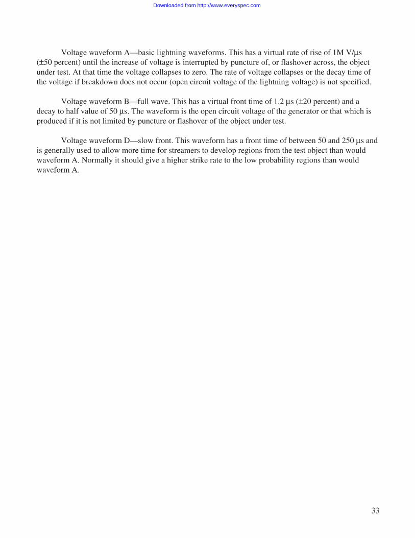
Component A—first return stroke. This has a peak current of 200 000 A (±10 percent) and anaction integral of 2×10⁶ (A2s) (±20 percent) with a total time duration not exceeding 500 µs. Thiscomponent may be unidirectional or oscillatory and the rate of rise time is intentionally not specified.
Component B—intermediate current. This has an average amplitude of 2 000 A (±10 percent)flowing for a maximum duration of 5 ms and transferring a maximum of 10 C. The waveform should beunidirectional, but may be rectangular, exponential, or linearly decaying. Most commonly, tests aremade with a double exponential waveshape.
Component C—continuing current. This transfers a charge of 200 C (±20 percent) in a timebetween 0.25 and 1.0 s. The waveform may be either rectangular, exponential, or linearly decaying.Most commonly, tests are made with rectangular currents of between 200 and 800 A.
Component D—subsequent stroke current. This has a peak amplitude of 100 000 A (±10 percent)and an action integral of 0.25×10⁶ (A2s) (±20 percent) with a total duration not exceeding 500 µs. Thiscomponent may be unidirectional or oscillatory and the rate of rise time is intentionally not specified.
Upset or damage generated to electronic equipment by a lightning-induced electromagnetic pulseis called indirect effects. The vehicle’s interactions with the electromagnetic pulse generate voltages andcurrents throughout the system. This testing can be divided into two sections: (1) Complete vehicle testand (2) electronic (box level) equipment tests.
A lightning-induced voltage (indirect effects) complete vehicle test comprises injectinga reduced magnitude lightning current pulse into the vehicle at various points and measuring the inducedvoltages and currents on the vehicle wiring harness. This requires a pulse current generator, wave-shaping impedances, return circuit system, and measurement equipment to monitor the applied threatand the system response.
Downloaded from http://www.everyspec.com
32
Test electrical/electronic equipment to ensure that induced transients do not cause damage to theequipment that results in loss of critical function or in a response (upset) that creates a hazard. Twotypes of testing verify damage and upset. Upset and transient damage (failure) analysis are two majortopics to be addressed when verifying lightning protection for complex digital systems utilizing solidstate electronic devices. Upset tests are typically conducted by coupling transients into an operatingsystem and monitoring critical system functions. Because upset of digital systems is fundamentally astatistical process or event, a transient single pulse test is not adequate. Use of multiple transients repre-sented by multiple stroke and/or multiple burst test waveforms is theoretically more correct than using asingle transient. Damage tests are typically applied to equipment inputs (powered but not functioning) atthe connector pins to determine if input circuits are damaged.
Voltage waveforms are used for verification testing. These waveforms represent the electricfields associated with a lightning strike. Voltage waveforms A and D are used to test for possible dielec-tric puncture and potential attachment for a lightning flash. Voltage waveform B is used to test forstreamers. These voltage waveforms are intentionally similar to those used in high voltage laboratoriesfor evaluating effects of lightning on electrical power systems. The objective setup, measurement, anddata requirements for each test are described in NSTS–07636.14
Important characteristics of the voltage waveforms (fig. 10) are as follows:
Figure 10. Voltage attachment test waveforms.
0
v
0t t
v
0t
v
Volta
ge (n
ot to
sca
le)
Flashover
Flashover
50%
Waveform A Waveform B Waveform D
Time (not to scale)
1.2 µs = 20% 50 µs = 20% 50 to 250 µs
= 1
000
V/µ
s ± 5
0%
dV/dt
Downloaded from http://www.everyspec.com
33
Voltage waveform A—basic lightning waveforms. This has a virtual rate of rise of 1M V/µs(±50 percent) until the increase of voltage is interrupted by puncture of, or flashover across, the objectunder test. At that time the voltage collapses to zero. The rate of voltage collapses or the decay time ofthe voltage if breakdown does not occur (open circuit voltage of the lightning voltage) is not specified.
Voltage waveform B—full wave. This has a virtual front time of 1.2 µs (±20 percent) and adecay to half value of 50 µs. The waveform is the open circuit voltage of the generator or that which isproduced if it is not limited by puncture or flashover of the object under test.
Voltage waveform D—slow front. This waveform has a front time of between 50 and 250 µs andis generally used to allow more time for streamers to develop regions from the test object than wouldwaveform A. Normally it should give a higher strike rate to the low probability regions than wouldwaveform A.
Downloaded from http://www.everyspec.com
34
6. CONCLUSIONS
Lightning protection assessment and design are critical functions in the development and designof an aerospace vehicle. The project’s Lightning Protection Engineer must be involved in the prelimi-nary design phase and remain an integral member of the design and development team throughoutconstruction of the vehicle and all verification testing. The guidelines in this document provide anoverview of the criteria necessary for an adequate lightning protection design.
Questions concerning lightning protection assessment and design for an aerospace vehicleshould be directed to ED44/Lowell Primm, Group Lead, Environments Group, 256–544–9145.
Downloaded from http://www.everyspec.com
35
REFERENCES
1. “Analysis of Apollo 12 Lightning Incident,” NASA Document No. MSC–01540, prepared jointlyby Marshall Space Flight Center, Kennedy Space Center, and Manned Spacecraft Center,National Aeronautics and Space Administration, February 1970.
2. Brook, M.; Holmes, C.R.; and Moore, C.B.: “Lightning and Rockets—Some Implications of theApollo 12 Lightning Event,” Naval Research Reviews, Vol. 23, No. 4, pp. 1–17, April 1970.
3. Christian, H.J.; Mazur, V.; Fisher, V.D.; Ruhnke, L.H.; Crouch, K.; and Perala, R.A.: “The Atlas/Centaur Lightning Strike Incident,” J. Geophys. Res., Vol. 94, pp. 13,169–13,177, 1989.
4. Federal Aviation Administration: “Protection of Aircraft Fuels Systems Against Lightning,”U.S. FAA Advisory Circular 25–3, Washington, DC, November 10, 1965.
5. “Bonding, Electrical, and Lightning Protection for Aerospace Systems,” MIL–B–5087B,Department of Defense, October 15, 1964.
6. Plumer, J.A.; and Robb, J.D.: “The Direct Effects of Lightning on Aircraft,” IEEE Trans.on Electromag. Com., EMC–24, pp. 158–172, 1982.
7. “Lightning Test Waveforms and Techniques for Aerospace Vehicles and Hardware,” Report ofSAE Committee AE–4, Special Task F, Society of Automotive Engineers, May 5, 1976.
8. “Lightning Test Waveforms and Techniques for Aerospace Vehicles and Hardware,” Reportof SAE Committee AE–4L, Society of Automotive Engineers, June 20, 1978.
9. “Lightning Qualification Test Techniques for Aerospace Vehicles and Hardware,” MIL–STD–1757, Department of Defense, June 17, 1980.
10. “Lightning Qualification Test Techniques for Aerospace Vehicles and Hardware,” MIL–STD–1757A, Department of Defense, June 20, 1983.
11. “Protection of Airplane Fuel Systems Against Fuel Vapor Ignition Due to Lightning,” U.S. FAAAdvisory Circular 20–53A, Federal Aviation Administration, Washington, DC, April 12, 1985.
12. “Lightning Protection Criteria Document,” NSTS–07636, NASA Johnson Space Center, 1973.
13. Perala, R.A.; Rudolph, T.; and Eriksen, F.: “Electromagnetic Interaction of Lightning WithAircraft,” IEEE Trans. on Electromag. Comp., EMC–24, pp. 173–203, 1982.
Downloaded from http://www.everyspec.com
36
14. “Lightning Protection Criteria Document,” NSTS–07636, Rev. E, NASA Johnson Space Center,March 19, 1988.
15. “Protection of Aircraft Electrical/Electronic Systems Against the Indirect Effects of Lightning,”Report of SAE Committee AE4L, Society of Automotive Engineers, Recommended Draft Advi-sory Circular, February 4, 1987.
16. “Lightning Protection of Aerospace Vehicles and Hardware,” DOD–STS–1795, Departmentof Defense, May 30, 1986.
17. Systems Engineering Handbook, 2nd Edition, Vols. 1 and 2, MSFC–HDBK–1912A, MSFC,July 1994.
18. Beard, K.V.K.; and Ochs, H.T.: “Cloud Electrification,” Rev. Geophys. Space Phys., Vol. 21,pp. 984–992, 1983.
19. Leteinturier, C.; Weidman, C.; and Hameslin, J.: “Current and Electric Field Derivativesin Triggered Lightning Return Strokes,” J. of Geo. Res., Vol. 95, pp. 818–828, 1990.
20. Johnson, D.L., Editor: “Terrestrial Environment (Climate) Criteria Guidelines for Use in Aero-space Vehicle Development, 1993 Revision,” NASA Technical Memorandum 4511, 1993.
21. “Lightning Protection Engineering Processes Document,” Systems Analysis & IntegrationLaboratory, MSFC–DOD–2259, MSFC, September 1993.
22. “EMP Susceptibility of Semiconductor Components,” Report D244–13042–1, Departmentof Defense, September 1974.
23. Fisher, F.A.; Plumer, J.A.; and Perala, R.A.: Lightning Protection of Aircraft, LightningTechnologies, Inc., Pittsville, MA, 1990.
Downloaded from http://www.everyspec.com
37
BIBLIOGRAPHY
Krider, E.P.: “75 Years of Research on the Physics of a Lightning Discharge,” Historical Essays onMeteorology 1919–1995, J.R. Fleming (ed.), American Meteorological Society, Boston, MA, 1996.
Ruhnke, L.H.; and Latham, J., (eds.): Proceedings in Atmospheric Electricity, A Deepak Publishing,Hampton, VA, 1983.
Uman, M.A.: Lightning, McGraw-Hill, New York, NY, 1969.
Downloaded from http://www.everyspec.com
REPORT DOCUMENTATION PAGE Form ApprovedOMB No. 0704-0188
Public reporting burden for this collection of information is estimated to average 1 hour per response, including the time for reviewing instructions, searching existing data sources,gathering and maintaining the data needed, and completing and reviewing the collection of information. Send comments regarding this burden estimate or any other aspect of thiscollection of information, including suggestions for reducing this burden, to Washington Headquarters Services, Directorate for Information Operation and Reports, 1215 JeffersonDavis Highway, Suite 1204, Arlington, VA 22202-4302, and to the Office of Management and Budget, Paperwork Reduction Project (0704-0188), Washington, DC 20503
1. AGENCY USE ONLY (Leave Blank)
17. SECURITY CLASSIFICATIONOF REPORT
NSN 7540-01-280-5500 Standard Form 298 (Rev. 2-89)Prescribed by ANSI Std. 239-18298-102
14. SUBJECT TERMS
13. ABSTRACT (Maximum 200 words)
12a. DISTRIBUTION/AVAILABILITY STATEMENT
11. SUPPLEMENTARY NOTES
6. AUTHORS
7. PERFORMING ORGANIZATION NAMES(S) AND ADDRESS(ES) 8. PERFORMING ORGANIZATIONREPORT NUMBER
9. SPONSORING/MONITORING AGENCY NAME(S) AND ADDRESS(ES) 10. SPONSORING/MONITORINGAGENCY REPORT NUMBER
4. TITLE AND SUBTITLE 5. FUNDING NUMBERS
12b. DISTRIBUTION CODE
18. SECURITY CLASSIFICATIONOF THIS PAGE
19. SECURITY CLASSIFICATIONOF ABSTRACT
20. LIMITATION OF ABSTRACT
16. PRICE CODE
15. NUMBER OF PAGES
2. REPORT DATE 3. REPORT TYPE AND DATES COVERED
May 1999 Technical Memorandum
Lightning Protection Guidelines for Aerospace Vehicles
C.C. Goodloe
George C. Marshall Space Flight CenterMarshall Space Flight Center, Alabama 35812
National Aeronautics and Space AdministrationWashington, DC 20546−0001
Prepared by System Analysis and Integration Laboratory, Science and Engineering Directorate
Unclassified-UnlimitedSubject Category 18Nonstandard Distribution
NASA/TM—1999–209734
M–946
Unclassified UnclassifiedUnclassified Unlimited
48
A03
lightning environment, lightning protection, waveforms, direct and indirect effects, strike zones
This technical memorandum provides lightning protection engineering guidelines and technical procedures used by the George C. Marshall Space Flight Center (MSFC) Electromagnetics and Aerospace Environments Branch for aerospace vehicles. The overviews illustrate the technical support available to project managers, chief engineers, and design engineers to ensure that aerospace vehicles managed by MSFC are adequately protected from direct and indirect effects of lightning. Generic descriptions of the lightning environment and vehicle protection technical processes are presented. More specific aerospace vehicle requirements for lightning protection design, performance, and interface characteristics are available upon request to the MSFC Electromagnetics and Aerospace Environments Branch, mail code EL23.