19
LIGO-G070xxx-00-M December 19, 2007 Single Stage ISI Electronics Overview Ben Abbott Mohana Mageswaran December 19, 2007
| Date post: | 18-Dec-2015 |
| Category: |
Documents |
| View: | 215 times |
| Download: | 1 times |

LIGO-G070xxx-00-M
December 19, 2007
Single Stage ISI Electronics Overview
Ben AbbottMohana MageswaranDecember 19, 2007

2LIGO-G070xxx-00-M
December 19, 2007
Single Stage ISI

3LIGO-G070xxx-00-M
December 19, 2007
HAM views springs and sensorsunder the table top
access to a vertical sensor

4LIGO-G070xxx-00-M
December 19, 2007
HAM ISI Sensors
Horiz.Coil
VerticalGS-13
HorizontalGS-13
V.Coil
H.CPS
Horiz.Coil
VerticalGS-13
HorizontalGS-13
V.Coil
H.CPS
Horiz.Coil
VerticalGS-13
HorizontalGS-13
V.Coil
H.CPS
Pod 1
Pod 2
Pod 3
Capacitive Position Sensor Satellite
Capacitive Position Sensor Satellite
To ISI Interface 2
To ISI Interface 1
STS-2
To STS-2 Interface
VerticalGS-13
HorizontalGS-13
Witness
Vert. Pos.
Sensor
Vert. Pos.
Sensor
Vert. Pos.
Sensor

5LIGO-G070xxx-00-M
December 19, 2007
HAM 6 Drive
Vert. Pos.
Sensor
Horiz.Coil
VerticalGS-13
HorizontalGS-13
V.Coil
H.CPS
Vert. Pos.
Sensor
Horiz.Coil
VerticalGS-13
HorizontalGS-13
V.Coil
H.CPS
Vert. Pos.
Sensor
Horiz.Coil
VerticalGS-13
HorizontalGS-13
V.Coil
H.CPS
Pod 1
Pod 2
Pod 3
From ISI Coildriver 2
From ISI Coildriver 1

6LIGO-G070xxx-00-M
December 19, 2007
Stage 2 Control at Stanford
stage 1 motion
stage 2 motionw/ feedback isolation
stage 2 motionw/ damping
HAM req
Preliminary data
7LIGO-G070xxx-00-M
December 19, 2007
Seismic Isolation Electronics
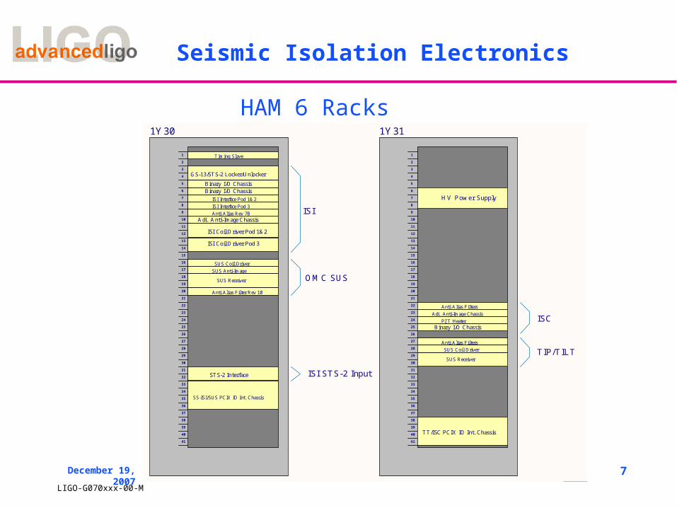
HAM 6 Racks
1
1
2
2
3
3
4
4
5
5
6
6
D D
C C
B B
A A
Title
Number RevisionSize
B
Date: 12/18/2007 Sheet ofFile: C:\Ben\..\AdLSEI_Single_Stage_All_Systems.SchDocDrawn By:
1
2
3
4
5
6
7
8
9
10
11
12
13
14
15
16
17
18
19
20
21
22
23
24
25
26
27
28
29
30
31
32
33
34
35
36
37
38
39
40
41
1Y31
1
2
3
4
5
6
7
8
9
10
11
12
13
14
15
16
17
18
19
20
21
22
23
24
25
26
27
28
29
30
31
32
33
34
35
36
37
38
39
40
41
1Y30
TT/ISC PCIX IO Int. Chassis
ISI Interface Pod 1&2ISI Interface Pod 3
AdL Anti-Image Chassis
ISI Coil Driver Pod 3
ISI Coil Driver Pod 1&2
GS-13/STS-2 Locker/Unlocker
Anti Alias Rev 7B
Anti Alias Filter Rev 10
Binary I/O ChassisBinary I/O Chassis
SUS Coil Driver
Timing Slave
SUS Anti-Image
SUS Receiver
Anti Alias FiltersAdL Anti-Image Chassis
PZT HeaterBinary I/O Chassis
SUS Receiver
Anti Alias FiltersSUS Coil Driver
SS-ISI/SUS PCIX IO Int. Chassis
ISI
OMC SUS
TIP/TILT
ISC
STS-2 Interface ISI STS-2 Input
HV Power Supply
8LIGO-G070xxx-00-M
December 19, 2007
Seismic Isolation Electronics
Seven kinds of Electronics modules are needed for the HAM ISI Installation.
» Binary I/O Interface» Anti-Image Chassis» Anti-Alias Chassis Rev.7B» STS-2 Interface» ISI Interface Chassis» ISI Coil Driver» Capacitive Position Sensor Field Interface Box» LSU Locker/Unlocker
CDS Electronics Modules
Some Electronics are shared in the HAM6 rack.» Timing Board» PCIX I/O Chassis» Anti-Alias Chassis Rev.10

9LIGO-G070xxx-00-M
December 19, 2007
Single Stage ISI Interface
Inputs come from 4 GS-13 seismometers, and 4 Capacitive position Sensors. Chassis interfaces signals with ADCs, DACs and Binary I/O modules.
GS-13 Interface has switchable x1 and x10 gain, and two stages of simultaneously switchable whitening with 0.1 Hz zeroes, and 1 Hz poles.
Capacitive Position Interface Card supplies power, and routs signals. It has no gain or filtration.
ISI Interface Block Diagram

10LIGO-G070xxx-00-M
December 19, 2007
Capacitive Position Sensor Interface Box

11LIGO-G070xxx-00-M
December 19, 2007
Capacitive Position Sensor Noise
12LIGO-G070xxx-00-M
December 19, 2007
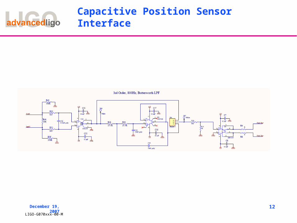
Capacitive Position Sensor Interface

13LIGO-G070xxx-00-M
December 19, 2007
Seismic Isolation Electronics
ISI Information Block Diagram
Analog Signal
AA
Inte
rfac
e B
oard
D05
0387
AA
Filt
er B
oard
D05
0374
PC
IX A
DC
Ada
pter
Boa
rd
D06
0060
Gen
eral
Sta
ndar
ds A
DC
Opt
eron
Fro
nt E
nd P
roce
ssor
PCIX Ex
AdL Anti-Alias Chassis
PCIX IO Chassis
Analog Signal
AI Interface B
oard D050373
AI F
ilter Board D
050368
PC
IX D
AC
Adapter B
oard D
060061
General S
tandards DA
C
Opteron F
ront End P
rocessor
PCIX Ex
AdL Anti-Image Chassis
PCIX IO Chassis
CDS Network
Myrinet
CDS Network
Myrinet
14LIGO-G070xxx-00-M
December 19, 2007
Actuator Electronics
1. The Coarse and Fine actuators used in the ISI are custom manufactured by PSI (Planning Systems Inc.).
2. The coarse actuators are used to actuate in the horizontal and vertical directions at each of the three locations around the HAM.
3. Coarse actuator is capable of generating a continuous force of maximum 20 lb and the Coil Driver is capable of providing the current to produce this force.

15LIGO-G070xxx-00-M
December 19, 2007
Actuators Coarse Fine
Magnitude Wire Gauge 18 AWG round wire 24 AWG round wire
Continuous Force 20 lb 10 lb
Resistance(@25 deg C) 6.1 ohm 9.3 ohm
Inductance ~5 mH ~3 mH
Self-resonant frequency ~200 KHz ~275 KHz
Hi-Pot Test(500 VDC for 60 sec) >500 MOhm >500 MOhm
Force Constant at Central Position 6.74 lb/amp 6.9 lb/amp
Imax = (20 lb) / (6.74 lb/amp) = 3A
Vmax = (3 A) * (6.1 ohm) = 18.3 volts
(neglect the cable loss)

16LIGO-G070xxx-00-M
December 19, 2007
Noise Specifications
The output current noise requirements are most restrictive for the Fine driver and are as follows:
Frequency Noise Requirement
Freq > 30 Hz 3nA/sqrt(Hz)
10 Hz < freq < 30 Hz 8 nA/sqrt(Hz)
1 Hz < freq < 10 Hz 45 nA/sqrt(Hz)
freq < 1Hz (45 nA/sqrt(Hz) * (1/freq)

17LIGO-G070xxx-00-M
December 19, 2007
• The DAC input is +/- 20 V and noise level is 5µV/sqrt(Hz).
• The DAC stage is surrounded by a digital whitening and analog de whitening filter to address the noise associated with the DAC.
• De whitening Filter 2 Poles @ 0.4 Hz and 2 Zeros @ 15.9 Hz is added to lower the noise after the differential DAC Input.

18LIGO-G070xxx-00-M
December 19, 2007
Noise measured using the SR785

19LIGO-G070xxx-00-M
December 19, 2007
Complete assembled chassis


![[XLS]health.mp.gov.inhealth.mp.gov.in/nrhm/md/HMIS/HMIS mandatory disclosure.xls · Web viewMANDAW KHEDA MOHANA SIRWEL ANDAD BAMNALA KALDHA RODIYA BADGAON BEHRAMPUR BISTAN KHOTHA](https://static.documents.pub/doc/80x56/5ab1742b7f8b9abc2f8cb5a4/xls-mandatory-disclosurexlsweb-viewmandaw-kheda-mohana-sirwel-andad-bamnala-kaldha.jpg)

![mohana uravu[1]](https://static.documents.pub/doc/80x56/577d296b1a28ab4e1ea6ba92/mohana-uravu1.jpg)


