152

�
������������ ���������������������� ���� ������ ������
������������������� !�"#$���%!


Please Read Before Use
Thank you for purchasing our product.
This Operation Manual explains the handling methods, structure and maintenance of this product, among others, providing theinformation you need to know to use the product safely.
Before using the product, be sure to read this manual and fully understand the contents explained herein to ensure safe use ofthe product.The CD or DVD that comes with the product contains operation manuals for IAI products.When using the product, refer to the necessary portions of the applicable operation manual by printing them out or displayingthem on a PC.
After reading the Operation Manual, keep it in a convenient place so that whoever is handling this product can reference itquickly when necessary.
[Important]• This Operation Manual is original.• The product cannot be operated in any way unless expressly specified in this Operation Manual. IAI shall assume
no responsibility for the outcome of any operation not specified herein.• Information contained in this Operation Manual is subject to change without notice for the purpose of product
improvement.• If you have any question or comment regarding the content of this manual, please contact the IAI sales office near
you.• Using or copying all or part of this Operation Manual without permission is prohibited.• The company names, names of products and trademarks of each company shown in the sentences are registered
trademarks.

CAUTION
1. Use EnvironmentPCON controllers can be used in an environment corresponding to pollution degree 2 or equivalent.
2. PC Software and Teaching Pendant Models New functions have been added to the entire PCON controller series.To support these new features, the communication protocol has been changed to the general Modbus(Modbus-compliant) mode. As a result, the existing PC software programs and teaching pendants compatiblewith RCP2 controllers can no longer be used.If you are using this controller, use a compatible PC software program and/or teaching pendant selected from thefollowing models.
skrameRledoMPC software (with RS232Ccommunication cable) RCM-101-MW
PC software (with USB communicationcable) RCM-101-USB
Teaching pendant RCM-TSimple teaching pendant RCM-EData setting unit RCM-P
All are compatible with existing RCP2controllers.
3. Recommendation for Backing Up Latest DataThis product uses nonvolatile memory to store the position table and parameters. Normally the memory will retainthe stored data even after the power is disconnected. However, the data may be lost if the nonvolatile memorybecomes faulty.We strongly recommend that the latest position table and parameter data be backed up so that the data can berestored quickly when the controller must be replaced for a given reason.The data can be backed up using the following methods:[1] Save to a CD or FD from the PC software.[2] Create a position table sheet or parameter sheet and keep a written record of backup.

4. Using Rotary Actuators in Multi-rotation SpecificationRotary actuators of multi-rotation specification models can be set to operate in the multi-rotation mode orlimited-rotation mode using a parameter.
4.1 Note
Pay attention to the PIO pattern parameter setting for the following controllers.Each controller does not support relative coordinate specification in the PIO pattern specified below:
[1] PCON-C/CG: PIO pattern = 5 (User parameter No. 25)[2] PCON-CY: PIO pattern = 0 (User parameter No. 25)
4.2 Applicable Models
*-IP82-C-NOCP*-063-02-P82-I-LBTR-2PCR*-IP82-GC-NOCP*-063-03-P82-I-LBTR-2PCR*-IP82-YC-NOCP*-063-02-P82-I-LCTR-2PCR
Actuators
RCP2-RTCL-I-28P-30-360-*
Controllers
PCON-SE-28PI-*
CAUTION

CE MarkingIf a compliance with the CE Marking is required, please follow Overseas Standards Compliance Manual (ME0287) that is provided separately.

Table of Contents
Safety Guide ...........................................................................................................................................1
1. Overview ..........................................................................................................................................91.1 Introduction ....................................................................................................................................................91.2 Differences from Air Cylinders in Control Functions.....................................................................................101.3 How to Read Model Name ...........................................................................................................................121.4 System Configuration...................................................................................................................................131.5 Steps from Unpacking to Adjustment by Trial Operation..............................................................................141.6 Warranty.......................................................................................................................................................16
2. Specifications.................................................................................................................................182.1 Basic Specifications .....................................................................................................................................182.2 Name and Function of Each Part of the Controller.......................................................................................192.3 External Dimensions ....................................................................................................................................20
3. Installation and Wiring....................................................................................................................213.1 Installation Environment...............................................................................................................................213.2 Supplied Voltage..........................................................................................................................................213.3 Noise Elimination Measures and Grounding ................................................................................................223.4 Heat Radiation and Installation ....................................................................................................................233.5 External Connection Diagram ......................................................................................................................243.6 Wiring the Power Supply..............................................................................................................................253.7 Wiring the Brake Forced-release Switch ......................................................................................................253.8 Wiring the Emergency Stop Circuit ..............................................................................................................26
3.8.1 Cutting Off the Drive Signal (Standard) ............................................................................................263.8.2 Cutting Off the Motor Drive Power ....................................................................................................28
1.6.1 Warranty Period................................................................................................................................ 161.6.2 Scope of Warranty............................................................................................................................ 161.6.3 Honoring the Warranty...................................................................................................................... 161.6.4 Limited Liability..................................................................................................................................161.6.5 Conditions of Conformance with Applicable Standards/Regulations, Etc.,
and Applications................................................................................................................................171.6.6 Other Items Excluded from Warranty................................................................................................ 17
3.9 Connecting the Actuator...............................................................................................................................293.9.1 Motor Relay Cable ............................................................................................................................293.9.2 Encoder Relay Cable........................................................................................................................30
3.10 Connecting the I/O Flat Cable......................................................................................................................313.11 Connecting the Communication Cable.........................................................................................................32
4. Position Table Settings ..................................................................................................................334.1 Details of the Position Table ........................................................................................................................334.2 Notes on the ROBO Gripper ........................................................................................................................38
5. Operation Using I/O Signals ..........................................................................................................405.1 Interface Circuit ............................................................................................................................................40
5.1.1 External Input Specifications.............................................................................................................405.1.2 External Output Specifications..........................................................................................................415.1.3 Recognition of Input Signals .............................................................................................................42
5.2 Proximity Switch Type..................................................................................................................................435.2.1 Explanation of I/O Signals.................................................................................................................435.2.2 Timings after Power On ....................................................................................................................45
Steps from Initial Startup to Actuator Adjustment........................................................................45Normal Operating Procedure ......................................................................................................46

5.2.5 Positioning Operation .......................................................................................................................51� Meaning of Position Detection Output Signals (LS0, LS1, LS2)..................................................52� Notes on Setting the Positioning Band........................................................................................52� Speed Change during Movement................................................................................................53� Pausing during Movement...........................................................................................................54� Forced Return in Case of Emergency .........................................................................................54
5.3 Standard Type .............................................................................................................................................555.3.1 Explanation of I/O Signals.................................................................................................................555.3.2 Timings after Power On ....................................................................................................................57
� Steps from Initial Startup to Actuator Adjustment........................................................................57� Normal Operating Procedure ......................................................................................................58
5.3.3 Position Table and Parameter Settings Required for Operation .......................................................60� Test Operation ............................................................................................................................60Safety speed during manual feed .....................................................................................................60Speed override for move commands from the PLC ..........................................................................60� Full-scale Operation ....................................................................................................................61Power-saving when the standby time after power on is long ............................................................61Power-saving when the standby time at the target position is long...................................................61Complete signal output mode ...........................................................................................................61
5.3.4 Homing .............................................................................................................................................625.3.5 Positioning Operation .......................................................................................................................63
� Meaning of Positioning Complete Output Signals (PE0, PE1, PE2)............................................64� Notes on Setting the Positioning Band........................................................................................64� Speed Change during Movement................................................................................................65� Pausing during Movement...........................................................................................................66� Forced Return in Case of Emergency .........................................................................................66� Constant Pitch Feed....................................................................................................................67
5.3.6 Zone Output Signal...........................................................................................................................695.3.7 Push-motion Operation .....................................................................................................................705.3.8 Examples of Tact Time Reduction Combining Zone Outputs and 3 Stop Points ..............................76
5.4 Power-saving Modes at Standby Positions ..................................................................................................785.5 Using Rotary Actuators in Multi-rotation Specification..................................................................................81
5.5.1 How to Use .......................................................................................................................................81
6. Parameter Settings ........................................................................................................................826.1 Parameter List..............................................................................................................................................826.2 Detail Explanation of Parameters.................................................................................................................83
6.2.1 Parameters Relating to Actuator Stroke Range ................................................................................83� Soft Limits (No.3/4 LIMM/LIML)...................................................................................................83� Home Direction (No.5 ORG) .......................................................................................................83� Home Offset (No.22 OFST).........................................................................................................84� Zone Limits (1: No. 1/2 ZONM/ZONL 2: No. 23/24 ZNM2/ZNL2)................................................84
6.2.2 Parameters Relating to Actuator Operating Characteristics..............................................................85� Default Speed (No.8 VCMD) .......................................................................................................85� Default Acceleration/Deceleration (No.9 ACMD).........................................................................85� Default Positioning Band (In-position) (No.10 INP) .....................................................................85� Current-limiting Value during Homing (No.13 ODPW) ................................................................85� Current-limiting Value at Standstill after Positioning (No.12 SPOW)...........................................85� Speed Override (No.46 OVRD)...................................................................................................85� Default Direction of Excited Phase Signal Detection (No.28 PHSP) ...........................................86� Excited Phase Signal Detection Time (No.29 PHSP)..................................................................86� Automatic Servo-off Delay Time (No.36 ASO1/ No.37 ASO2/ No.38 ASO3) ..............................87� Default Standstill Mode (No.53 CTLF) ........................................................................................87� Push Speed (No.34 PSHV) .........................................................................................................88� Push-motion Completion Judgment Time (No.6 PSWT) .............................................................88� Enable Function (No.42 FPIO) ....................................................................................................89� Home Check Sensor Input Polarity (No.43 AIOF) .......................................................................89� Home Sensor Input Polarity (No. 18, LS) ....................................................................................90� Ball Screw Lead (No. 77, LEAD) .................................................................................................90� Axis Operation Type (No. 78, ATYP) ..........................................................................................90� Rotational Axis Mode Selection (No. 79, ATYP) .........................................................................90

Shortcut Selection for Rotational Axis (No. 80, ATYP)................................................................91Absolute Unit (No. 83, ETYP)......................................................................................................91
6.2.3 Parameters Relating to External Interface ........................................................................................92PIO Pattern Selection (No.25 IOPN) ...........................................................................................92Positioning Complete Signal Output Mode (No.39FPIO) ............................................................92Servo-on Input Disable Selection (No.21 FPIO)..........................................................................93SIO Communication Speed (No.16 BRSL)..................................................................................93Minimum Delay Time for Slave Transmitter Activation (No.17 RTIM) .........................................93Silent Interval Multiplication Factor (No.45 SIVM) .......................................................................93
6.2.4 Servo Gain Adjustment .....................................................................................................................94Servo Gain Number (No.7 PLG0) ...............................................................................................94Speed Loop Proportional Gain (No.31 VLPG).............................................................................94Speed Loop Integral Gain (No.32 VLPT) ....................................................................................95Torque Filter Time Constant (No.33 TRQF)................................................................................95
7. Troubleshooting .............................................................................................................................967.1 What to Do When A Problem Occurs...........................................................................................................967.2 Alarm Level Classification ............................................................................................................................977.3 Alarms, Causes and Actions ........................................................................................................................98
(1) Operation Cancellation Alarms....................................................................................................98(2) Cold Start Alarms ......................................................................................................................101
7.4 Messages Displayed during Teaching Pendant Operation ........................................................................1047.5 Common Problems and Recommended Actions .......................................................................................106
I/O Signals Cannot Be Sent or Received to/from the PLC. .......................................................106The ALM Lamp Illuminates after the Power Is Turned On.........................................................106After Turning On the Power, the SV Lamp Does Not Illuminate upon Servo-on Signal Input....106With an Actuator Installed in Vertical Orientation, Positioning Completes Prematurely. ...........107With an Actuator Installed in Vertical Orientation, Noise Generates during Downward Movement.107
Vibration Occurs when the Actuator Is at Standstill...................................................................107The Actuator Overshoots while Decelerating to a Stop.............................................................107Stopped Position Sometime Deviates from the Home Position or Target Position....................107The Actuator Moves Slow during Push-motion Operation.........................................................107The Actuator Moves Only a Half, or as Much as Twice, the Specified Travel. ..........................107A Servo Error Occurred while the ROBO Gripper Was Moving.................................................108The Actuator Malfunctions when the Servo Is Turned On after Turning On the Power. ............109The SV Lamp Blinks..................................................................................................................109
* Appendix...........................................................................................................................................110List of Specifications of Connectable Actuators ....................................................................................................110Correlation diagram of speed and load capacity for the slider type (motor-straight type) ...................................122Correlation diagram of speed and load capacity for the slider type (motor-reversing type) ................................123Correlation diagram of speed and load capacity for the standard rod type ...........................................................124Correlation diagram of speed and load capacity for the single-guide type ............................................................125Correlation diagram of speed and load capacity for the double-guide type...........................................................126Correlation diagram of speed and load capacity for the dustproof/splash-proof type............................................127Correlation diagram of speed and load capacity for the RCP3 slider type ............................................................128Correlation diagram of speed and load capacity for the RCP3 table type .............................................................129Push Force and Current-limiting Value..................................................................................................................130Position Table Record ...........................................................................................................................................137ParameterChange History
Record .................................................................................................................................................138139......................................................................................................................................................
Push Speed (No.34 PSHV) .........................................................................................................88Push-motion Completion Judgment Time (No.6 PSWT) .............................................................88Enable Function (No.42 FPIO) ....................................................................................................89Home Check Sensor Input Polarity (No.43 AIOF) .......................................................................89Home Sensor Input Polarity (No. 18, LS) ....................................................................................90Ball Screw Lead (No. 77, LEAD) .................................................................................................90Axis Operation Type (No. 78, ATYP) ..........................................................................................90Rotational Axis Mode Selection (No. 79, ATYP) .........................................................................90


1
Safety Guide“Safety Guide” has been written to use the machine safely and so prevent personal injury or property damage beforehand. Make sure to read it before the operation of this product.
Safety Precautions for Our ProductsThe common safety precautions for the use of any of our robots in each operation.
No. OperationDescription Description
1 Model Selection
� This product has not been planned and designed for the application where high level of safety is required, so the guarantee of the protection of human life is impossible. Accordingly, do not use it in any of the following applications.1) Medical equipment used to maintain, control or otherwise affect human
life or physical health.2) Mechanisms and machinery designed for the purpose of moving or
transporting people (For vehicle, railway facility or air navigation facility)3) Important safety parts of machinery (Safety device, etc.)
� Do not use the product outside the specifications. Failure to do so may considerably shorten the life of the product.
� Do not use it in any of the following environments.1) Location where there is any inflammable gas, inflammable object or
explosive2) Place with potential exposure to radiation3) Location with the ambient temperature or relative humidity exceeding
the specification range4) Location where radiant heat is added from direct sunlight or other large
heat source5) Location where condensation occurs due to abrupt temperature
changes 6) Location where there is any corrosive gas (sulfuric acid or hydrochloric
acid)7) Location exposed to significant amount of dust, salt or iron powder8) Location subject to direct vibration or impact
� For an actuator used in vertical orientation, select a model which is equipped with a brake. If selecting a model with no brake, the moving part may drop when the power is turned OFF and may cause an accident such as an injury or damage on the work piece.

2
No. OperationDescription Description
2 Transportation � When carrying a heavy object, do the work with two or more persons or utilize equipment such as crane.
� When the work is carried out with 2 or more persons, make it clear who is to be the leader and who to be the follower(s) and communicate well with each other to ensure the safety of the workers.
� When in transportation, consider well about the positions to hold, weight and weight balance and pay special attention to the carried object so it would not get hit or dropped.
� Transport it using an appropriate transportation measure.The actuators available for transportation with a crane have eyebolts attached or there are tapped holes to attach bolts. Follow the instructions in the operation manual for each model.
� Do not step or sit on the package.� Do not put any heavy thing that can deform the package, on it.� When using a crane capable of 1t or more of weight, have an operator
who has qualifications for crane operation and sling work.� When using a crane or equivalent equipments, make sure not to hang a
load that weighs more than the equipment’s capability limit.� Use a hook that is suitable for the load. Consider the safety factor of the
hook in such factors as shear strength.� Do not get on the load that is hung on a crane.� Do not leave a load hung up with a crane.� Do not stand under the load that is hung up with a crane.
3 Storage andPreservation
� The storage and preservation environment conforms to the installation environment. However, especially give consideration to the prevention of condensation.
� Store the products with a consideration not to fall them over or drop due to an act of God such as earthquake.
4 Installation and Start
(1) Installation of Robot Main Body and Controller, etc.� Make sure to securely hold and fix the product (including the work part). A
fall, drop or abnormal motion of the product may cause a damage or injury.Also, be equipped for a fall-over or drop due to an act of God such as earthquake.
� Do not get on or put anything on the product. Failure to do so may cause an accidental fall, injury or damage to the product due to a drop of anything, malfunction of the product, performance degradation, or shortening of its life.
� When using the product in any of the places specified below, provide a sufficient shield.1) Location where electric noise is generated2) Location where high electrical or magnetic field is present3) Location with the mains or power lines passing nearby4) Location where the product may come in contact with water, oil or
chemical droplets

3
No. OperationDescription Description
(2) Cable Wiring� Use our company’s genuine cables for connecting between the actuator
and controller, and for the teaching tool.� Do not scratch on the cable. Do not bend it forcibly. Do not pull it. Do not
coil it around. Do not insert it. Do not put any heavy thing on it. Failure to do so may cause a fire, electric shock or malfunction due to leakage or continuity error.
� Perform the wiring for the product, after turning OFF the power to the unit, so that there is no wiring error.
� When the direct current power (+24V) is connected, take the great care of the directions of positive and negative poles. If the connection direction is not correct, it might cause a fire, product breakdown or malfunction.
� Connect the cable connector securely so that there is no disconnection or looseness. Failure to do so may cause a fire, electric shock or malfunction of the product.
� Never cut and/or reconnect the cables supplied with the product for the purpose of extending or shortening the cable length. Failure to do so may cause the product to malfunction or cause fire.
4 Installation and Start
(3) Grounding� The grounding operation should be performed to prevent an electric shock
or electrostatic charge, enhance the noise-resistance ability and control the unnecessary electromagnetic radiation.
� For the ground terminal on the AC power cable of the controller and the grounding plate in the control panel, make sure to use a twisted pair cable with wire thickness 0.5mm2 (AWG20 or equivalent) or more for grounding work. For security grounding, it is necessary to select an appropriate wire thickness suitable for the load. Perform wiring that satisfies the specifications (electrical equipment technical standards).
� Perform Class D Grounding (former Class 3 Grounding with ground resistance 100� or below).

4
No. OperationDescription Description
4 Installation and Start
(4) Safety Measures� When the work is carried out with 2 or more persons, make it clear who is
to be the leader and who to be the follower(s) and communicate well with each other to ensure the safety of the workers.
� When the product is under operation or in the ready mode, take the safety measures (such as the installation of safety and protection fence) so that nobody can enter the area within the robot’s movable range. When the robot under operation is touched, it may result in death or serious injury.
� Make sure to install the emergency stop circuit so that the unit can be stopped immediately in an emergency during the unit operation.
� Take the safety measure not to start up the unit only with the power turning ON. Failure to do so may start up the machine suddenly and cause an injury or damage to the product.
� Take the safety measure not to start up the machine only with the emergency stop cancellation or recovery after the power failure. Failure to do so may result in an electric shock or injury due to unexpected power input.
� When the installation or adjustment operation is to be performed, give clear warnings such as “Under Operation; Do not turn ON the power!” etc. Sudden power input may cause an electric shock or injury.
� Take the measure so that the work part is not dropped in power failure or emergency stop.
� Wear protection gloves, goggle or safety shoes, as necessary, to secure safety.
� Do not insert a finger or object in the openings in the product. Failure to do so may cause an injury, electric shock, damage to the product or fire.
� When releasing the brake on a vertically oriented actuator, exercise precaution not to pinch your hand or damage the work parts with the actuator dropped by gravity.
5 Teaching � When the work is carried out with 2 or more persons, make it clear who is to be the leader and who to be the follower(s) and communicate well with each other to ensure the safety of the workers.
� Perform the teaching operation from outside the safety protection fence, if possible. In the case that the operation is to be performed unavoidably inside the safety protection fence, prepare the “Stipulations for the Operation” and make sure that all the workers acknowledge and understand them well.
� When the operation is to be performed inside the safety protection fence, the worker should have an emergency stop switch at hand with him so that the unit can be stopped any time in an emergency.
� When the operation is to be performed inside the safety protection fence, in addition to the workers, arrange a watchman so that the machine can be stopped any time in an emergency. Also, keep watch on the operation so that any third person can not operate the switches carelessly.
� Place a sign “Under Operation” at the position easy to see.� When releasing the brake on a vertically oriented actuator, exercise
precaution not to pinch your hand or damage the work parts with the actuator dropped by gravity.
* Safety protection Fence : In the case that there is no safety protection fence, the movable range should be indicated.

5
No. OperationDescription Description
6 Trial Operation � When the work is carried out with 2 or more persons, make it clear who is to be the leader and who to be the follower(s) and communicate well with each other to ensure the safety of the workers.
� After the teaching or programming operation, perform the check operation one step by one step and then shift to the automatic operation.
� When the check operation is to be performed inside the safety protection fence, perform the check operation using the previously specified work procedure like the teaching operation.
� Make sure to perform the programmed operation check at the safety speed. Failure to do so may result in an accident due to unexpected motion caused by a program error, etc.
� Do not touch the terminal block or any of the various setting switches in the power ON mode. Failure to do so may result in an electric shock or malfunction.
7 AutomaticOperation
� Check before starting the automatic operation or rebooting after operation stop that there is nobody in the safety protection fence.
� Before starting automatic operation, make sure that all peripheral equipment is in an automatic-operation-ready state and there is no alarm indication.
� Make sure to operate automatic operation start from outside of the safety protection fence.
� In the case that there is any abnormal heating, smoke, offensive smell, or abnormal noise in the product, immediately stop the machine and turn OFF the power switch. Failure to do so may result in a fire or damage to the product.
� When a power failure occurs, turn OFF the power switch. Failure to do so may cause an injury or damage to the product, due to a sudden motion of the product in the recovery operation from the power failure.

6
No. OperationDescription Description
8 Maintenanceand Inspection
� When the work is carried out with 2 or more persons, make it clear who is to be the leader and who to be the follower(s) and communicate well with each other to ensure the safety of the workers.
� Perform the work out of the safety protection fence, if possible. In the case that the operation is to be performed unavoidably inside the safety protection fence, prepare the “Stipulations for the Operation” and make sure that all the workers acknowledge and understand them well.
� When the work is to be performed inside the safety protection fence, basically turn OFF the power switch.
� When the operation is to be performed inside the safety protection fence, the worker should have an emergency stop switch at hand with him so that the unit can be stopped any time in an emergency.
� When the operation is to be performed inside the safety protection fence, in addition to the workers, arrange a watchman so that the machine can be stopped any time in an emergency. Also, keep watch on the operation so that any third person can not operate the switches carelessly.
� Place a sign “Under Operation” at the position easy to see.� For the grease for the guide or ball screw, use appropriate grease
according to the Operation Manual for each model.� Do not perform the dielectric strength test. Failure to do so may result in a
damage to the product.� When releasing the brake on a vertically oriented actuator, exercise
precaution not to pinch your hand or damage the work parts with the actuator dropped by gravity.
� The slider or rod may get misaligned OFF the stop position if the servo is turned OFF. Be careful not to get injured or damaged due to an unnecessary operation.
� Pay attention not to lose the cover or untightened screws, and make sure to put the product back to the original condition after maintenance and inspection works.Use in incomplete condition may cause damage to the product or an injury.
* Safety protection Fence : In the case that there is no safety protection fence, the movable range should be indicated.
9 Modificationand Dismantle
� Do not modify, disassemble, assemble or use of maintenance parts not specified based at your own discretion.
10 Disposal � When the product becomes no longer usable or necessary, dispose of it properly as an industrial waste.
� When removing the actuator for disposal, pay attention to drop of components when detaching screws.
� Do not put the product in a fire when disposing of it.The product may burst or generate toxic gases.
11 Other � Do not come close to the product or the harnesses if you are a person who requires a support of medical devices such as a pacemaker. Doing so may affect the performance of your medical device.
� See Overseas Specifications Compliance Manual to check whether complies if necessary.
� For the handling of actuators and controllers, follow the dedicated operation manual of each unit to ensure the safety.

7
Alert IndicationThe safety precautions are divided into “Danger”, “Warning”, “Caution” and “Notice” according to the warning level, as follows, and described in the Operation Manual for each model.
Level Degree of Danger and Damage Symbol
Danger This indicates an imminently hazardous situation which, if the product is not handled correctly, will result in death or serious injury. Danger
Warning This indicates a potentially hazardous situation which, if the product is not handled correctly, could result in death or serious injury. Warning
CautionThis indicates a potentially hazardous situation which, if the product is not handled correctly, may result in minor injury or property damage.
Caution
Notice This indicates lower possibility for the injury, but should be kept to use this product properly. Notice

8

9
1. Overview
1. Overview
1.1 Introduction As a dedicated controller for our RCP2 and RCP3 actuators, this controller becomes smaller and more affordable and incorporates a new set of features to offer greater convenience and safety, while maintaining the functions of the RCP2 controller. This controller also provides power-saving functions to address the growing need for saving energy. The key features and functions of this controller are summarized below.
� Limited I/O positioning points (3 points) The I/O signals are designed to function in the same manner as those of air cylinders. Two operation types are supported. The movement complete signals have different meanings in each type. • Proximity switch type --- Each movement complete signal works as an auto switch. Even when positioning operation is
not performed, a movement complete signal is output once the specified position is passed. • Standard type --- A movement complete signal is output only when positioning operation has completed following
a move command. * The controller is configured to support the proximity switch type before shipment.
� Separate zone output limits for each of 3 positions (rear end, intermediate point, front end) Before, the zone output limits were set by parameters and thus fixed to a certain width for all positions. To increase flexibility, setting fields have been added to the position table to allow different limits to be set for each position. This function is useful in preventing contact with peripheral equipment or reducing the tact time.
� Independent acceleration and deceleration settings The position table now has separate fields for acceleration and deceleration. The purpose of this change is to prevent works made of certain materials or having certain shapes from receiving impact or vibration when the actuator decelerates to a stop. By reducing the deceleration setting, a more gradual deceleration curve can be achieved.
� Limitation of feed speed during adjustment by test operation The feed speed during adjustment by test operation can be limited to ensure safety.
� Power-saving measures In general, pulse motors consume more holding current in standstill state than AC servo motors. Accordingly, this controller provides power-saving means by assuming situations where the motor is used in applications requiring a long standby time.
When actually starting your system or if you have encountered any problem, also refer to the manuals for the actuator, teaching pendant, PC software and/or any other component you are using, in addition to this manual.
This manual does not cover all possible deviations from normal operations or unexpected phenomena such as complex signal changes resulting from critical timings. Therefore, the reader should assume that items not described in this manual are “not permitted,” as a rule.
* This manual has been prepared with the utmost attention to ensure accuracy and completeness. However, there may still be inaccuracies and omissions. Should you find any inaccurate description or if you have any comment, please contact IAI.Keep this manual in a convenient place so that you can easily reference it whenever necessary.

10
1. O
verv
iew
1.2 Differences from Air Cylinders in Control Functions For those of you who have been using air cylinders and have never used motorized cylinders before, this section gives a brief explanation of how this controller is different from air cylinders. Read the following information and implement controls appropriate for your system.
Item Air cylinder PCON
Drive method Air pressure by solenoid valve control. Ball screw or timing belt drive using a pulse motor. Target position setting Mechanical stopper (including shock
absorber). Entry of a coordinate value in the “Position” field of the position table. A value can be entered by keying in a number from a PC/teaching pendant, or by moving the actuator to a desired position and then reading the achieved position directly. Example) Example of entry of “400 mm” stroke
Position No. Position 0 5 (mm), rear end 1 400 (mm), front end 2 200 (mm), intermediate point
Target position detection
Installation of a reed switch or other external detection sensor.
Judgment based on internal coordinates determined by the position information received from the position detector (encoder). No external detection sensor is required.
Speed setting Adjustment by a speed controller. Entry of a feed speed in the “Speed” field of the position table (unit: mm/sec). Note that the rated speed is set automatically as the default feed speed.
Acceleration/ deceleration setting
In accordance with the load, air supply volume, and speed controller/solenoid valve performance.
Entry in the “Acceleration” and “Deceleration” fields of the position table (minimum setting unit: 0.01 G). Reference: 1 G = Gravitational acceleration Note that the rated acceleration and deceleration are set automatically as the default acceleration and deceleration. Desired values can be set in fine steps to achieve gradual acceleration/deceleration curves.
The greater the set value, the steeper the curve becomes. On the other hand, the smaller the set value, the more gradual the curve becomes.
Acceleration Deceleration
Start position of movement
Endposition

11
1. Overview
Item Air cylinder PCON Position check upon power on
Judgment using a reed switch or other external detection sensor.
When the power is turned on, mechanical coordinates are not stored in the controller and thus the current position is not yet determined. For this reason, a rear end move command must be executed after the power has been turned on, in order to establish coordinates. The actuator performs homing first, and then moves to the rear end.
[1] The actuator moves toward the mechanical end on the motor side at the homing speed.
[2] The actuator contacts the mechanical end, reverses its direction, and stops temporarily at the home position.
[3] The actuator moves to the rear end at the speed set in the “Speed” field of the position table.
(Note) Make sure there is no obstacle along the homing path.
Hom
e po
sitio
n
Rea
r end
Pow
e r-o
n po
sitio
n
[1]
[2]
[3]

12
1. O
verv
iew
1.3 How to Read Model Name
<Series>
<Type> CY: Dedicated controller for 3-point
positioning by I/Os
<Actuator characteristics> [Motor flange size] 20P: 20, square 28P: 28, square 28SP: 28, square (RA3 type only) 42P: 42, square 56P: 56, square [Encoder type] I: Incremental
High-acceleration loading specification
Specifiation for connecting the simple absolute unit
<Power-supply voltage> 0: 24 VDC
<I/O flat cable length> 0: No cable 2: 2 m 3: 3 m 5: 5 m
<I/O signal type> NP��NPN [Sink] PN��PNP [Source]

13
1. Overview
1.4 System Configuration This controller performs positioning to 3 points (rear end, intermediate point, front end) via a PLC and I/O signals.
Caution: If the actuator is not equipped with a brake, the BK terminal need not be connected.
Standard teaching pendant
Host system <PLC>
PCON-CY controller
Flat cable <supplied with the controller>
Cable length: 2 m* If a PLC will not be used,
disable the servo-on input by the applicable parameter.
24-VDC I/O power supply
PCPC software
(optional)RS232C type USB type
RCP2 actuator
Brake forced-release switch
Power-supply terminal block
External EMG switch
Input power supply 24 VDC

14
1. O
verv
iew
1.5 Steps from Unpacking to Adjustment by Trial Operation If you are using this controller for the first time, refer to the steps explained below and perform the specified tasks carefully by making sure you check all necessary items and connect all required cables.
1. Checking the items in the package
Should you find any of the following items missing or of a wrong model type, please contact your IAI sales agent.
� Controller � Actuator � I/O flat cable � Motor cycle � Encoder cable PCON-CY CB-PACY-PIO *** CB-RCP2-MA *** CB-RCP2-PA ***
� Operation manual
<Options> � Teaching pendant � PC software RCM-T (standard) RS232C type <RCM-101-MW> RCM-E (simple) USB type <RCM-101-USB> RCM-P (data setting) (Each software program comes with a cable.)
2. Installation
[1] Affix the actuator and install the robot hand → Refer to the operation manual for your actuator. [2] Install the controller → Chapter 3, “Installation and Wiring”
3. Wiring/connection
• Wire the 24-V power supply. • Wire the brake forced-release switch (if the actuator is equipped with a brake). • Connect the grounding wire to ground. • Wire the emergency stop circuit and motor drive power supply. • Connect the motor cable and encoder cable. • Connect the I/O flat cable.
4. Turning on the power and checking for alarms
Confirm first that the emergency stop circuit is not actuated, and then supply the 24-V power. If the monitor LED [SV/ALM] on the front face of the controller illuminates in orange for 2 seconds and then turns off, the controller is normal. If the [SV/ALM] illuminates in red, it means that an alarm is present. In this case, connect a PC or teaching pendant and check the nature of the alarm, and remove the cause by referring to Chapter 7, “Troubleshooting.”
5. Setting a PIO pattern/safety speed
Set the MANU operation mode to [Teaching mode 1: Enable safety speed / Inhibit PIO] on the PC or teaching pendant. In this condition, set appropriate values in parameter No. 25 (PIO pattern selection) and parameter No. 35 (Safety speed). * The factory settings of PIC pattern and safety speed are “Standard type” and “100 mm/s or less,” respectively.
→ Chapter 6, “Parameter Settings”

15
1. Overview
6. Operating when the servo is ON
Confirm that the slider or rod is not contacting a mechanical end. If the slider or rod is contacting a mechanical end, move it away from the mechanical end. If the actuator is equipped with a brake, move the actuator after turning ON the forced brake release switch to forcibly releasethe brake. At this time, be careful not to get your hand pinched or the robot hand damaged by the actuator dropping suddenly due to its dead weight.
Turn ON the servo using the PC or teaching pendant. If the actuator enters a servo lock state and the monitor LED [SV/ALM] on the front face of the controller illuminates in green,the controller is normal.
7. Confirming the safety circuit operation
Confirm that the emergency cutoff circuit (or motor drive-power cutoff circuit) operates normally. → Chapter 3, “Installation and Wiring”
8. Setting a target position
Use the teaching pendant or PC to set a target position in the “Position” field of the position table (rear end, front end, intermediate point). * If any movement operation is started without setting a target position first, the message “No movement data” will be
displayed. Determine an appropriate target position by fine-tuning the work or robot hand. * Once a target position is set, other items (speed, acceleration/deceleration, positioning band, etc.) will be set to their defaults
automatically. → Chapter 4, “Position Table Settings”
9. Adjustment by test operation
Input a move command from the PLC to perform positioning. If necessary, perform the following fine adjustments: • Depending on the weight, material and/or shape of the work, vibration or noise may occur. If you notice undesirable vibration
or noise, lower the speed, acceleration and/or deceleration. • You may also want to adjust the zone output signal limits and positioning band to prevent contact with peripheral equipment
or reduce the tact time. • If push-motion operation will be performed, select optimal current-limiting value, push-motion completion judgment time and
push speed.
→ Chapter 4, “Position Table Settings” → Chapter 5, “Operation Using I/O Signals”

16
1. O
verv
iew
1.6 Warranty
1.6.1 Warranty Period
Elapse of 18 months after the shipment from IAIElapse of 12 months after the delivery to the specified location
One of the following periods, whichever is shorter:
(1) The breakdown or problem in question pertains to our product as delivered by us or our authorized dealer. (2) The breakdown or problem in question occurred during the warranty period. (3) The breakdown or problem in question occurred while the product was in use for an appropriate purpose under the
conditions and environment of use specified in the operation manual and catalog. (4) The breakdown or problem in question was caused by a specification defect or problem, or by the poor quality of
our product.
Our products are covered by warranty when all of the following conditions are met. Faulty products covered by warranty will be replaced or repaired free of charge:
[1] Anything other than our product[2] Modification or repair performed by a party other than us (unless we have approved such modification or repair) [3] Anything that could not be easily predicted with the level of science and technology available at the time of shipment
from our company [4] A natural disaster, man-made disaster, incident or accident for which we are not liable [5] Natural fading of paint or other symptoms of aging [6] Wear, depletion or other expected result of use [7] Operation noise, vibration or other subjective sensation not affecting function or maintenance
Note that the warranty only covers our product as delivered and that any secondary loss arising from a breakdown of our product is excluded from the scope of warranty.
Note that breakdowns due to any of the following reasons are excluded from the scope of warranty:
1.6.3 Honoring the WarrantyAs a rule, the product must be brought to us for repair under warranty.
1.6.2 Scope of Warranty
1.6.4 Limited Liability[1] We shall assume no liability for any special damage, consequential loss or passive loss such as a loss of expected
profit arising from or in connection with our product. [2] We shall not be liable for any program or control method created by the customer to operate our product or for the result
of such program or control method.

17
1. Overview
1.6.5 Conditions of Conformance with Applicable Standards/Regulations, Etc., and Applications
[1] Medical equipment pertaining to maintenance or management of human life or health [2] A mechanism or mechanical equipment intended to move or transport people (such as a vehicle, railway facility
or aviation facility)[3] Important safety parts of mechanical equipment (such as safety devices) [4] Equipment used to handle cultural assets, art or other irreplaceable items
1.6.6 Other Items Excluded from WarrantyThe price of the product delivered to you does not include expenses associated with programming, the dispatch of engineers, etc. Accordingly, a separate fee will be charged in the following cases even during the warranty period:
(1) If our product is combined with another product or any system, device, etc., used by the customer, the customer must first check the applicable standards, regulations and/or rules. The customer is also responsible for confirming that such combination with our product conforms to the applicable standards, etc. In such a case we will not be liable for the conformance of our product with the applicable standards, etc.
(2) Our product is for general industrial use. It is not intended or designed for the applications specified below, which require a high level of safety. Accordingly, as a rule our product cannot be used in these applications. Contact us if you must use our product for any of these applications:
(3) Contact us at the earliest opportunity if our product is to be used in any condition or environment that differs from what is specified in the catalog or operation manual.
[1] Guidance for installation/adjustment and witnessing of test operation [2] Maintenance and inspection [3] Technical guidance and education on operating/wiring methods, etc. [4] Technical guidance and education on programming and other items related to programs

18
2. S
peci
ficat
ions
2. Specifications
2.1 Basic Specifications
Specification item DescriptionYC-NOCPledoM
Number of controlled axes 1 axis per unitPower-supply voltage 24 VDC +10%/-10%Power-supply capacity 2 A max.Control method Field-weakening vector control (patent pending)Encoder resolution 800 P/rev
Positioning command Separate commands for positioning to rear end, front end andintermediate point
Backup memoryPosition number data and parameters are stored in the nonvolatilememory.Serial EEPROM life: Approx. 100,000 times of rewriting
PIO interface 24-VDC insulation4 input points
• Front end move command• Rear end move command• Intermediate point move command• Servo-on
6 output points• Front end movement complete• Rear end movement complete• Intermediate point movement complete• Ready (or zone output under the standard type)• Homing complete• *Alarm
LED indicator SV (green) --- Whether or not the servo is on / ALM (red) --- Whetheror not an alarm is present.
Serial communication RS485, 1 channel (conforming to the Modbus protocol)Encoder interface Incremental specification conforming to EIA RS-422A/423AForced release of electromagnetic brake 24 V is applied to the BK terminal on the power-supply terminal block.
Actuator cable: 20 m or shorterCable lengthI/O flat cable: 5 m or shorter
Dielectric strength 500 VDC 10 mΩEnvironment Surrounding air temperature 0 to 40°C
Surrounding humidity 85% RH or below (non-condensing)Surrounding environment Refer to 3.1 Installation EnvironmentStorage temperature -10 to 65°CStorage humidity 90% RH or below (non-condensing)
Vibration resistance 10 to 57 Hz in all X/Y/Z directions / Single amplitude: 0.035 mm(continuous), 0.075 mm (intermittent)
Protection class Natural air cooling (IP20)Weight 128 g or belowExternal dimensions 35 (W) x 120 (H) x 68 (D) mm

19
2. Specifications
2.2 Name and Function of Each Part of the Controller
BK Connection terminal for the brake forced-release switch to be used when the actuator is equipped with a brake. Connect the opposite side of the switch to 24 V.
MPI, MPO
Contacts for cutting off the motor drive power to achieve a safety level of safety category 1. MPI and MPO connect to the input side and output side of the motor power supply, respectively. (If these contacts are not used, connect them using a jumper cable. The controller is shipped with MPI and MPO connected by a jumper cable.)
24 V Positive side of the 24-VDC input power supply.
0 V Negative side of the 24-VDC input power supply.
EMG - Connection terminal for the emergency stop circuit (for cutting of motor drive signals). A common ground is used, so connect the opposite side of the emergency stop switch (or contacts) to the positive side of the 24-VDC input power supply.
� Model indication of the connected actuator type The type, ball screw lead and stroke of the actuator are indicated. When connecting the cables, confirm that the actuator is
of the correct specifications. Example of indication:
The actuator type is RA4C. The ball screw lead is 5 mm. The stroke is 200 mm.
PIO connector
Connects the PLC and PIO.
Connects the teaching pendant/PC.
The model of the connected actuator is indicated here.
Connects the motor cable.
SIO connector
Motor connector
Power-supply terminal block
Status indicator LED
SV (Green) --- Indicates whether or not the servo is on.
If this LED is blinking, the controller is in the automatic servo-off mode.
ALM (Red) --- Indicates whether or not an alarm is present.
The PIO pattern number is indicated here.If the PIO pattern is different for each system, indicate the applicable PIO pattern here to prevent confusion.
The I/O signal type is indicated here. NPN --- Sink type PNP --- Source type
Encoder connector
Connects the encoder cable.

20
2. S
peci
ficat
ions
2.3 External Dimensions An external view and dimensions of this product are shown below.
∅5

21
3. Installation and Wiring
3. Installation and Wiring
Pay due attention to the environment where the controller is installed.
3.1 Installation EnvironmentThis product is capable for use in the environment of pollution degree 2*1 or equivalent.*1 Pollution Degree 2 : Environment that may cause non-conductive pollution or transient conductive pollution by frost
(IEC60664-1)[1] Installation EnvironmentDo not use this product in the following environment.• Location where the surrounding air temperature exceeds the range of 0 to 40°C• Location where condensation occurs due to abrupt temperature changes• Location where relative humidity exceeds 85%RH• Location exposed to corrosive gases or combustible gases• Location exposed to significant amount of dust, salt or iron powder• Location subject to direct vibration or impact• Location exposed to direct sunlight• Location where the product may come in contact with water, oil or chemical droplets• Environment that blocks the air vent [Refer to 3.3 Noise Elimination Measures and Grounding]
When using the product in any of the locations specified below, provide a sufficient shield.• Location subject to electrostatic noise• Location where high electrical or magnetic field is present• Location with the mains or power lines passing nearby
[2] Storage and Preservation Environment• Storage and preservation environment follows the installation environment. Especially, when the product is to be left
for a long time, pay special attention to condensed water.Unless specially specified, moisture absorbency protection is not included in the package when the machine is delivered. In the case that the machine is to be stored in an environment where dew condensation is anticipated, take the condensation preventive measures from outside of the entire package, or directly after opening the package.
3.2 Supplied VoltageThe controller takes a supplied voltage of 24 VDC ± 10%.(Maximum power-supply current: 2 A)

22
3. In
stal
latio
n an
d W
iring
[2] Cautions on wiring method
Use a twisted cable to connect the 24-VDC external power supply.Separate the controller wiring from high-power lines of motive power circuits, etc. (Do not tie them together or place in thesame cable duct.)If you want to extend the motor or encoder cable beyond the length of the supplied cable, contact IAI.
(2) Noise sources and eliminationNoise generates from many sources, but the most common sources of noise you should consider when designing a systemare solenoid valves, magnet switches and relays. Noise generation from these components can be prevented by the methodexplained below.
AC solenoid valves, magnet switches, relays
Method --- Install a surge absorber in parallel with the coil
PointConnect to each coil over the shortest possible wiring distance.When a surge absorber is installed on the terminal block, etc., its noiseelimination effect will decrease if the distance from the coil is long.
3.3 Noise Elimination Measures and GroundingThe following explains the noise elimination measures that should be taken when using this controller.
(1) Wiring and power connection[1] Provide dedicated class-D grounding using a grounding wire with a size of 2.0 to 5.5 mm2 or larger.
ControllerOtherequip-ment
ControllerOtherequip-ment
Connect a cable ofthe largest possiblesize over the shortestpossible distance
Metalenclosure
.nrettapsihtdiovAdooGgnidnuorgD-ssalC

23
3. Installation and Wiring
3.4 Heat Radiation and Installation Design the control panel size, controller layout and cooling method so that the temperatures around the controller will always be kept to 40°C or below. Mount the controller vertically on the wall, as shown below. Since cooling is provided by means of natural convection, follow this orientation and provide a minimum clearance of 50 mm above and below the controller to allow sufficient airflows to circulate. If you are installing multiple controllers side by side, provide a fan on top of the controllers to agitate the airflows as an effective way to keep the surrounding air temperatures constant. Provide a minimum clearance of 80 mm between the front face of the controller and the wall (cover).
Regardless of whether you are installing one or more controllers, provide sufficient clearances around each controller to permit easy access for installation and removal of the controller.
Fan At least 50 mm
At least 50 mm
At least 80 mm
Airflow

24
3. In
stal
latio
n an
d W
iring
Brown 1 Red 1 Orange 1 Yellow 1 Green 1 Blue 1 Purple 1 Gray 1 White 1 Black 1 Brown 2 Red 2
Orange
Gray
White
Yellow
Pink
Yellow (Green)
Yellow Orange (black 2)
Orange (red 2)
Yellow (black 1)
Yellow (red 1)
White (black 1)
White (red 1)
Light blue (black 1)
Light blue (red 1)
For teaching pendant/PC connection
Brake release switch
PCON-CY controller
Flat cable
External EMG switch
Input power supply 24 VDC
Terminal block
24-VDC power supply for I/O signals
0 V (NPN specification) 24 V (PNP specification)
Load
0 V (NPN specification) 24 V (PNP specification)
LoadLoadLoadLoadLoad
Tighten together with a mounting screw.
Motor relay cable Actuator
Motor
Encoder relay cable
Encoder
Holding brake
3.5 External Connection Diagram An example of standard wiring is shown below.
(Note) The PIO signal names are those based on the proximity switch type. The color of the encoder relay cable is different for the robot cable specification. Refer to 3.9.2, “Encoder Relay
Cable.”

25
3. Installation and Wiring
3.6 Wiring the Power Supply Connect the positive side and negative side of the 24-VDC power supply to the 24-V terminal and N terminal on the power-supply terminal block, respectively.
Use a wire satisfying the following specifications.
Item Specification Applicable wire Twisted wire: AWG 22 (0.3 mm2) (copper wire)
(Note) Provide proper termination to prevent shorting due to contact with wire offcut. If the wiring path is long, provide a relay terminal block and connect the original wire to
another wire of a different size.
Temperature rating of insulation sheath
60°C or above
Length of bare wire
3.7 Wiring the Brake Forced-release Switch If the actuator is equipped with a brake, provide a forced-release switch to permit a reset means during startup adjustment or in case of emergency. The customer must provide the switch (24 VDC, with a minimum contact capacity of 0.2 A). Connect one side of the switch to the positive side of the 24-VDC power supply, and connect the other side to the BK terminal on the power-supply terminal block. The brake will be released when the switch is closed.
Danger: If the actuator is oriented vertically, exercise due caution when releasing the brake to prevent the slider/rod from dropping unexpectedly to pinch your hand or damage the robot hand or work.
Push with a flat-head screwdriver to open the cable inlet.
Input power supply 24 VDC (Max. 2 A per unit)
Power-supply terminal block Cable inlet
Input power supply
Relay terminal block Power-supply terminal block
Brake forced-release switch
Input power supply 24 VDC (Max. 2 A per unit)
Power-supply terminal block

26
3. In
stal
latio
n an
d W
iring
3.8 Wiring the Emergency Stop Circuit
3.8.1 Cutting Off the Drive Signal (Standard)
Connect one side of the external EMG switch to the positive side of the 24-VDC power supply, and connect the other side to the BK terminal.
(Note) The EMG switch on the teaching pendant works only on the controller connected to the switch.
PCON-CY controller
Power-supply terminal block
Power-supply terminal block (2nd)
SIO connectorTeaching pendant
EMG switch
24-VDC input power supply
(Max. 2 A per unit)
External EMG switch
Connectiondetectionsignal (H)
SIO connector connection detection
circuit
EMG signal detection (H)
Time constant
Drive stop signal (L)
Motordrivecircuit
Power-supply terminal block (3rd)
27
3. Installation and Wiring
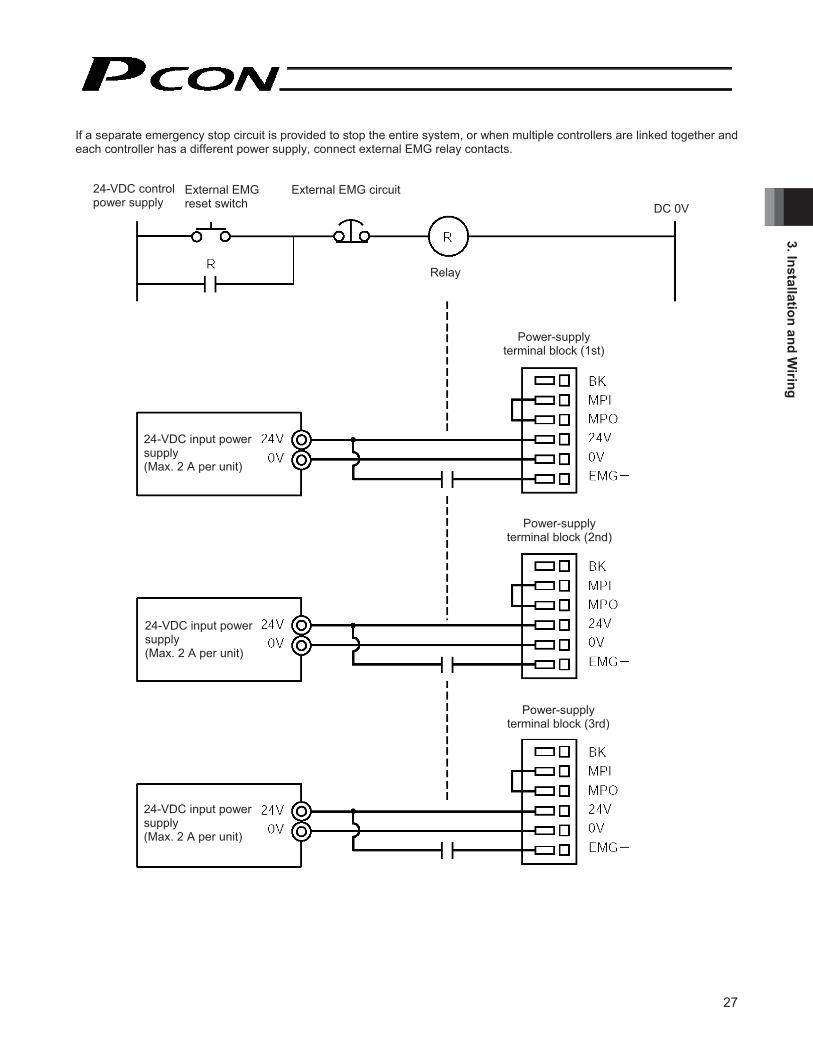
If a separate emergency stop circuit is provided to stop the entire system, or when multiple controllers are linked together andeach controller has a different power supply, connect external EMG relay contacts.
24-VDC control power supply
External EMG reset switch
External EMG circuit
Relay
Power-supply terminal block (1st)
Power-supply terminal block (2nd)
24-VDC input power supply (Max. 2 A per unit)
Power-supply terminal block (3rd)
24-VDC input power supply (Max. 2 A per unit)
24-VDC input power supply (Max. 2 A per unit)
DC 0V

28
3. In
stal
latio
n an
d W
iring
3.8.2 Cutting Off the Motor Drive Power
If the motor drive power must be cut off in order to meet the required safety category of the entire system, connect external EMG relay contacts between the MPI terminal and MPO terminal. Also connect the 24-V controller power supply to the EMG terminal.
(Note) The EMG switch on the teaching pendant cuts off the motor driver signal. It does not cut off the motor drive power.
For driving the motorThese lines are shorted internally.
For driving the motorThese lines are shorted internally.
For driving the motorThese lines are shorted internally.
24-VDC control power supply
External EMG reset switch
External EMG circuit
Relay
Power-supply terminal block (1st)
Power-supply terminal block (2nd)
24-VDC input power supply (Max. 2 A per unit)
Power-supply terminal block (3rd)
24-VDC input power supply (Max. 2 A per unit)
24-VDC input power supply (Max. 2 A per unit)
DC 0V

29
3. Installation and Wiring
3.9 Connecting the Actuator
3.9.1 Motor Relay Cable
• Connect the motor relay cable to the MOT connector. Signal table of controller-end connector (CN2)
Pin No. Signal Wire color Description A1 A Orange Motor drive line (phase -A) A2 VMM Gray Motor power line A3 B White Motor drive line (phase -B) B1 A Yellow Motor drive line (phase +A) B2 VMM Pink Motor power line B3 B Yellow (Green) Motor drive line (phase +B)
Controller end Actuator end
CN2 pin layout CN1 pin layout
Housing: 1-1318119-3 (AMP) Housing: SLP-06V (J.S.T. Mfg.) Receptacle contact: 1318107-1 Socket contact: BSF-21T-P1.4
OrangeGray White
Yellow Pink
Yellow (Green)
Yellow Gray
Orange
Yellow (Green)
PinkWhite
Cable color Signal abbreviation Pin No. Cable color Signal
abbreviation Pin No.

30
3. In
stal
latio
n an
d W
iring
3.9.2 Encoder Relay Cable
• Connect the encoder relay cable to the PG connector. Signal table of controller-end connector (CN2)
Pin No. Signal abbreviation Description 1 F.G Shielded wire 2 - (Not used)3 - (Not used)4 - (Not used)5 GND 6 5V
Encoder power output
7 VPS Encoder control signal output 8 - (Reserved) 9 ENB10 ENB
Encoder differential signal phase-B input
11 ENA12 ENA
Encoder differential signal phase-A input
13 BK - Brake power – 14 BK + Brake power + 15 - 16 -
(Not used)
Controller end Actuator endCN2 pin layout CN1 pin layout
Housing: XMP-18V (J.S.T. Mfg.) Contact: BXA-001T-P0.6
Retainer: XMS-09V
PurpleWhite (with purple)
Blue
White (with blue)
Yellow White (with yellow)
GreenRed
White (with red)
Drain
RedGray
Brown GreenPurplePink
Yellow Orange
Blue
Drain
Brown GreenPurplePink
BlueOrangeYellow
RedGray
Drain
BlueWhite (with blue)
Yellow White (with yellow)
White (with red)Red
Green
PurpleWhite (with purple)
Drain
Cable color Signal abbreviation Pin No.
Cable color Signal abbreviation Pin No.
Standard cable Robot cable
Robot cable Standard cable
Standard cable Robot cable
Housing: PHDR-16VS (J.S.T. Mfg.) Contact: SPHD-001T-P0.5
(Reserved)
Enter the cable length (L) in *** (up to 20 m). Example) 080 = 8 m
--

31
3. Installation and Wiring
3.10 Connecting the I/O Flat Cable
Signal name No.
Proximity switch type Standard type Color Wiring
1 24 V Brown-1 2 0 V Red-1 3 Rear end move command input Rear end move command Orange-1 4 Front end move command input Front end move command Yellow-1
5 Intermediate point move command input Intermediate point move command Green-1
6 Servo-on command input Servo-on command input Blue-1 7 Rear end detection output Rear end positioning complete output Purple-1
8 Front end detection output Front end positioning complete output Gray-1
9 Intermediate point detection output Intermediate point positioning complete output White-1
10 Ready output Zone output Black-111 Homing complete output Homing complete output Brown-2 12 Alarm output Alarm output Red-2
Flat cable (pressure- welded)
Warning: When checking the continuity of the flat cable, exercise due caution not to bend the female pins on the connector outward. It may cause contact failure, resulting in malfunction.
Red 2
Brown 1
Cable type:
Housing: Contact:

32
3. In
stal
latio
n an
d W
iring
3.11 Connecting the Communication Cable Connect the communication cable to the SIO connector.
Brown Yellow
RedOrange
BlueGreen
Shorting wire UL1004AWG28 (Black)
Yellow Orange
Brown/Green
Black
Red/BlueBlackShield
Pin layout of cable-end connector
RS485 conversion adapter end Controller end
Cable color Signal abbreviation Pin No. Cable color Signal
abbreviationPin No.
Not connected to the shield.

33
4. Position Table Settings
4. Position Table Settings To move the actuator to a specified position, basically you must enter the target position in the “Position” field of the positiontable.A target position can be specified as an absolute coordinate indicating a distance from the home (absolute mode), or as a relative coordinate indicating a relative travel from the current position (incremental mode). Once a target position is entered, all other fields will be automatically populated by the defaults set by the corresponding parameters. The defaults vary depending on the actuator characteristics.
4.1 Details of the Position Table The position table is explained by using the PC software screen as an example. (The display on the teaching pendant is different.)
(1) No. • Each number indicates a position data number. The respective numbers are defined as follows: No. 0 --- Entry field for conditions to move to the rear end. No. 1 --- Entry field for conditions to move to the front end. No. 2 --- Entry field for conditions to move to the intermediate point.
(2) Position • Enter a target position of the front end, rear end or intermediate point, in mm. Absolute mode: Enter a distance from the actuator home. Incremental mode: The actuator is assumed to operate at a constant pitch. Enter a relative travel
from the current position. For example, you can move the actuator to the front end from the intermediate point via incremental moves at a 30-mm pitch. (Use of the standard type is recommended because zone output signals are available in this type.)
Absolute mode: The rear end is positioned 5 mm away from the home. Incremental mode: The front end is positioned 30 mm away from the current position. Absolute mode: The intermediate point is positioned 200 mm away from the home.
* On the teaching pendant, an equal sign indicates that the applicable position is set in the incremental mode.
Position Speed Acceleration Deceleration Push Threshold [mm] [mm/s] [G] [G] [%] [%] [mm]
Positioning band
Zone + Zone – Incremental Comment[mm] [mm]
Acceleration/deceleration
modeCommand
modeStandstill
mode
Rear end
Front end Intermediate point
Position

34
4. P
ositi
on T
able
Set
tings
(3) Speed • Enter a speed at which to move the actuator, in mm/sec. The default speed varies depending on the actuator type.
(4) Acceleration/ deceleration
• Enter an acceleration/deceleration at which to move the actuator, in G. Basically, specify values inside the rated acceleration/deceleration range shown in the catalog. The input range is greater than the rated range specified in the catalog. This is to accommodate
situations where “the tact time must be reduced when the work is substantially lighter than the rated load capacity.”
If the work generates detrimental vibration during acceleration/deceleration, decrease the acceleration/deceleration settings.
Increasing the set value makes deceleration/deceleration quicker, while decreasing it makes deceleration/deceleration more gradual.
Caution: When setting speed and acceleration/deceleration, refer to the supplied specification list of supported actuators and also consider the installation condition and load shape to determine appropriate values that will not cause the actuator to receive excessive impact or vibration.
To set values higher than the recommended values, the payload should be considered and the actuator characteristics vary depending on the model. Therefore, for the maximum settings allowed for each actuator model, please contact IAI’s Sales Engineering Section.
(5) Push • Select “positioning operation” or “push-motion operation.” The factory setting is “0.” 0: Normal positioning operation Other than 0: The set value indicates a current-limiting value, meaning that push-motion operation
is performed.
(6) Threshold • This field is not used with this controller. The factory setting is “0.”
Speed
Acceleration0.3 G
Deceleration0.2 G
Sta
rt po
sitio
n
Time
Targ
et p
ositi
on

35
4. Position Table Settings
(7) Positioning band • What this field means is different in “positioning operation” and “push-motion operation.” “Positioning operation”: In the proximity switch type, this field defines the width within which the movement complete signal
turns ON. In the standard type, this field defines how far before the target position the movement complete
signal turns ON. The factory setting is “0.1” mm.
Proximity switch type
Movement complete signal
Targ
et p
ositi
on
Positioning band
Standard type
Increasing the positioning band quickens the starting of next sequence operation, and consequently the tact time becomes shorter. Set an optimal value by considering the balance of the entire system.
The movement complete signal turns ON here.
Targ
et p
ositi
on
Positioning band
“Push-motion operation”: This field defines the maximum push distance to be applied during push-motion operation from the target position. Consider the mechanical variation of the work and set an appropriate positioning band so that positioning will not complete before the work is contacted.
The work is contacted and push-motion operation is deemed complete, so the movement complete signal turns ON here.
Work
Targ
et p
ositi
on
Positioning band (maximum push distance)

36
4. P
ositi
on T
able
Set
tings
(8) Zone +/– • This field defines the range within which the zone output signal turns ON during operation of the standard type.
To increase flexibility, a different range can be set for each target position.
[Setting example]
(9) Acceleration/ deceleration mode
• This field is not used with this controller. The factory setting is “0.”
(10) Incremental • This field defines whether to use the absolute mode or incremental mode. The factory setting is “0.” 0: Absolute mode 1: Incremental mode
Warning: When using the proximity switch type, be sure to specify the absolute mode. If the incremental mode is specified, a position data error will occur.
(11) Command mode • This field is not used with this controller. The factory setting is “0.”
Position Zone + Zone – Comment [mm] [mm] [mm]
Rear end Front end
Intermediate point
Move command to the rear end
Move command to the front end
Move command to the intermediate point
Zone output signal
Zone output signal
Zone output signal
Rea
r end
Fron
t end
Inte
rmed
iate
poin
t
Hom
e
+ si
de li
mit

��
������������ ��������
����������������� �!�� "�#$���%�!����!%��!���$!�& '!()��*��+�� �!�� �,!��&&��!��'$��!��$!��-�.�� (�����������+�,/��%�!(�- �&�!���+��$!�& ���� ���+�� ��$!���(+!��& ���� ���!������$!�01 ���� �2�%�!���.��!(��$!��&&��-�,�!�& ���� ���.�,!(3�45�6���& '!()��*��+�� �!���(!�����,�!�3�7�#$!�%�-� (/��!����+����042������,�!��3��5�6.� ����-��!(* ) %%�� �!3�#$!��!��/����!�����!%��!��,/�1�(��!�!(�8 3��93��5�6.� ����-��!(* ) %%�� �!3�#$!��!��/����!�����!%��!��,/�1�(��!�!(�8 3���3��5�6.� ����-��!(* ) %%�� �!3�#$!��!��/����!�����!%��!��,/�1�(��!�!(�8 3��:3�;5�<.����!(* �- ��( ��� �!�#$!�&.��!�� � (�����!(* )- ��( ��!��� �(!�.-!��$!�$ ����+�-.((!��3�6��$ .+$��$!��&!-�%�-��!*!�� %�-.((!���(!�.-�� ��*�(�!������-- (���-!�'��$��$!��-�.�� (�� �!�=�� ���- ����� �=�!�-3=�+!�!(���/��$!�$ ����+�-.((!����( &��� ��( .�����$��%�� � �!)% .(�$3�#$!��!(* �(!������ �=�� �& ���� ���!*���� ��� !��� �� --.(3�#$!��-�.���$ ����+�-.((!���-���,!�-$!->!������$!�-.((!���� ��� (��-(!!�� %��$!�1?�� %�'�(!3�#$!��!(* ��.� ����-���/��.(��� %%��%�!(�!��&�!� %����&!-�%�!�����!�% �� '��+��$!�- �&�!�� �� %�& ���� ���+3�����-!�� �$ ����+�-.((!������(!@.�(!�=�& '!(�- ��.�&�� ���!-(!��!�3��A$!���$!�1B?����.!���$!��!C��� *!�- �����=��$!��!(* �'�����.(�� ���+���������$!��-�.�� (�'�������(��� *��+3�
<.����!(* �- ��( ��� �!
6.� ����-��!(* ) %%�� �!
D *!�- �������!(* �����.��6-�.�� (�� *!�!���
�!(* � ��6.� ����-��!(* ) %%�� �!�#$!�+(!!��BEF�,���>�3�
F!��/����!��%�!(�- �&�!�� �� %�& ���� ���+�.������$!��!(* ��.(��� %%���!-��#$����!��/����!�����!��,/���&�(��!�!(3�#�(+!��& ���� ��
GHIIJKLMNONPQLNIRNSKTNISUPVOHLLKPQOWPXKLKSHOKSXYJKLMNZONPQLNIIUPVQ[K\HIJKRNQNL]HQNRWQUOJKLMNZN__RNSK_QKL\NJUQUNPUPVUJONR\IKQKSQ[KJKLMNaUIIQHLPN__WHQNRWQUOWIIYH\NPKIW\JKN_WJ\KOU_UKSQURK]bGNLSKQWUIJLK_KLQNc]defNaKLZJWMUPVgNSKJWQhQWPSXYfNJUQUNPJ]e

38
4. P
ositi
on T
able
Set
tings
4.2 Notes on the ROBO Gripper (1) Finger Operation
[1] Definition of position With the two-finger type, the stroke specification indicates the total sum of travels by both fingers. In other words, the travel by one finger is one-half this stroke. A position is specified as a travel by one finger from the home position toward the closing direction. Therefore, the maximum command value is 5 mm for the GRS type, and 7 mm for the GRM type.
[2] Definition of speed and acceleration The command value applies to one finger. With the two-finger type, the relative speed and acceleration are double the command values, respectively.
[3] Gripper operation mode In applications where the work is to be gripped, be sure to use the “push-motion mode.” (Note) If the “positioning mode” is used, a servo error may occur while the work is gripped.
[Diagram of gripping force and current-limiting value]
Current-limiting value (%) Current-limiting value (%)
Grip
ping
forc
e (N
)
Current-limiting value (%) Current-limiting value (%)
Current-limiting value (%) Current-limiting value (%)
Grip
ping
forc
e (N
)
Grip
ping
forc
e P
(N)
Grip
ping
forc
e P
(N)
Grip
ping
forc
e P
(N)
Grip
ping
forc
e P
(N)

39
4. Position Table Settings
(2) Removing the gripped work The ROBO Gripper is structured in such a way that even when the controller power is cut off, the work gripping force will stillbe maintained by a self-lock mechanism. If you must remove the gripped work while the power is cut off, turn the open/close screw or remove one of the finger attachments to release the work.
[Two-finger type] Turn the open/close screw or remove one of the finger attachments.
[Three-finger type] Remove one of the finger attachments.
OP
EN
Open/close screw Turn counterclockwise using a flat-head screwdriver.
Finger attachment
Ope
ning
dire
ctio
n
Affixing bolt
Finger attachmentAffixing bolt

40
5. O
pera
tion
Usi
ng I/
O S
igna
ls
5. Operation Using I/O Signals This chapter explains the wiring/connection and operation timings you should know to perform positioning operation using a PLC and I/O signals. For PIO pattern, two types are available. The movement complete signals have different meanings in each type, so select an appropriate type according to your specific application. * The factory setting is to use the LS mode.
5.1 Interface Circuit The standard interface circuit conforms to the NPN specification, but the PNP specification type is also available as an option.To simplify wiring, a common power line is used for both the NPN specification and PNP specification. Accordingly you need not reverse the power connections when using the PNP specification.
5.1.1 External Input Specifications
Item Specification
Number of input points 4 points Input voltage 24 VDC ± 10% Input current 5 mA per circuit
Operating voltage ON voltage: Min. 18 V (3.5 mA) OFF voltage: Max. 6 V (1 mA)
Leak current Max. 1 mA per point Insulation method Photocoupler
Internal circuit configuration [NPN specification]
[PNP specification]
Controller
Controller
+24-V external power supply
+24-V external power supply
Eachinput
Eachinput
Internal circuit
Internal circuit

41
5. Operation U
sing I/O Signals
5.1.2 External Output Specifications
Item Specification
Number of input points 6 points Rated load voltage 24 VDC Maximum current 50 mA per point Residual voltage Max. 2 V Insulation method Photocoupler
Internal circuit configuration [NPN specification]
[PNP specification]
Controller
Controller
+24-V external power supply
+24-V external power supply
Internal circuit
Internal circuit
Each output
Each output
Load
Load
Load
Load

42
5. O
pera
tion
Usi
ng I/
O S
igna
ls
5.1.3 Recognition of Input Signals
The input signals of this controller have an input time constant to prevent malfunction due to chattering, noise, etc. Each input signal is switched when the new signal state has continued for at least 6 msec. In other words, when the input is switched from OFF to ON, the controller will recognize that the input signal is ON after 6 msec. The same applies when the input is switched from ON to OFF.
Input signal
Recognition by the controller
Not recognized Not recognized

43
5. Operation U
sing I/O Signals
5.2 Proximity Switch Type This type assumes applications where the servo is turned on/off frequently by the PLC or the automatic servo-off function is used. Use this type if your application meets the following conditions:
[1] The servo is turned off as a secondary safety measure when the emergency stop circuit is configured to directly cut off the input power. (Note) When the servo-on signal is turned OFF, the actuator will decelerate to a stop at the emergency stop torque
for a specified time, after which the servo will turn off. [2] The servo is turned off to reduce power consumption in case the standby time is long. [3] The actuator is equipped with a brake, and when reactive force is applied upon stopping due to clamping of the work,
etc., the servo is turned off to apply brake force to supplement the built-in brake. * Do not use push-motion operation.
Caution: The controller is shipped with the proximity switch type pre-selected, so you need not change any parameter if the proximity switch type is to be used.
5.2.1 Explanation of I/O Signals Pin No. Wire color Signal name Signal abbreviation Function overview
1 Brown 1 +24 V P24V2 Red 1 0 V N I/O power supply
3 Orange 1 Rear end move command input ST0 Move command to the rear end
4 Yellow 1 Front end move command input ST1 Move command to the front end
5 Green 1 Intermediate point move command input ST2 Move command to the intermediate point
6 Blue 1 Servo-on command input SON The servo remains on while this signal is ON. The servo remains off while this signal is OFF.
7 Purple 1 Rear end detection output LS0 This signal remains ON while the rear end is
recognized.
8 Gray 1 Front end detection output LS1 This signal remains ON while the front end is
recognized.
9 White 1 Intermediate point detection output LS2 This signal remains ON while the intermediate point
is recognized. 10 Black 1 Ready output SV This signal is output when the servo is on.
11 Brown 2 Homing complete output HEND This signal is OFF immediately after the power is turned on, and turns ON once homing is completed.
12 Red 2 Alarm output *ALM This signal remains ON while the actuator is normal, and turns OFF if an alarm has occurred.
� Move Command Input for Each Position (ST0, ST1, ST2) Since the number of positioning points is limited to three, you can use these inputs just like when controlling an air cylinder.While each signal remains ON, the actuator moves to the target position. If the signal turns OFF before the movement is completed, the actuator will decelerate to a stop. Before executing each move command, enter a target position as an absolute coordinate in the “Position” field under one of Nos. 0 to 2 in the position table. Input signal Target position Remarks
ST0 Rear end The target position is defined in the “Position” field under Position No. 0. ST1 Front end The target position is defined in the “Position” field under Position No. 1. ST2 Intermediate point The target position is defined in the “Position” field under Position No. 2.
� Servo-on Command Input (SON) The servo remains on while this signal is ON. To ensure safety, it is recommended that the PLC be configured to monitor the condition of the entire system and turn ON this signal once all conditions required for movement are satisfied.

44
5. O
pera
tion
Usi
ng I/
O S
igna
ls
� Detection Output for Each Position (LS0, LS1, LS2) Just like the LS signals of an air cylinder, each signal turns ON when the current actuator position is inside the positioning band set for the applicable target position. (Note) Even if the servo turns off or an emergency stop is actuated while the actuator is standing still at the target
position, the signal will remain ON as long as the actuator position is inside the positioning band.
Output signal Position detected Remarks
LS0 Rear end The detection position is defined in the “Position” and “Positioning band” fields under Position No. 0.
LS1 Front end The detection position is defined in the “Position” and “Positioning band” fields under Position No. 1.
LS2 Intermediate point The detection position is defined in the “Position” and “Positioning band” fields under Position No. 2.
� Ready Output (SV) This signal is a monitor signal indicating that the servo is on and the motor can be driven. While this signal is ON, the SV LED (green) on the front face of the enclosure is lit. The SV LED (green) blinks during the auto servo-off mode. Use this signal as a condition for starting a move command on the PLC side.
� Homing Complete Output (HEND) This signal is OFF immediately after the power is turned on. To establish the initial coordinate, only a rear end move command is accepted after power on. Once a rear end move command has been input, the actuator performs homing and then moves to the rear end. This signal will turn ON after the homing is completed. Once turned ON, this signal will remain ON until the input power is cut off. Use this signal as an interlock signal before homing.
(Reference) Acceptance of each move command before homing is explained below: [1] A rear end move command is accepted. [2] An intermediate point move command is not accepted. [3] A front end move command is accepted, but once the actuator moves forward at the homing speed and
contacts the mechanical end, the actuator will stop and a front end detection output (LS1) will turn ON. In this case, the LS1 signal should be recognized as a tentative signal. Movement to the front end is permitted to accommodate a situation where there is an obstacle between the actuator and the rear end.
� Alarm Output (*ALM) This signal remains ON while the actuator is normal, and turns OFF if an alarm has occurred. Cause the PLC to monitor the OFF state of this signal and provide an appropriate safety measure for the entire system. Check the nature of each alarm by connecting a PC/teaching pendant, and remove the cause. For details of alarms, refer to Chapter 7, “Troubleshooting.”

45
5. Operation U
sing I/O Signals
5.2.2 Timings after Power On
� Steps from Initial Startup to Actuator Adjustment [1] Confirm that the slider or rod is not contacting a mechanical end or that the work is not contacting any peripheral
equipment. [2] Cancel the emergency stop or connect the motor drive power. [3] Supply the 24-VDC I/O power (PIO connector pins 1 and 2). [4] Supply the 24-VDC controller power (24-V and 0-V terminals on the power-supply terminal block). [5] Set the minimum required parameters.
(Example) • To temporarily disable the servo-on input because the PLC is not yet ready to accept the input, change the value of Parameter No. 21 (Servo-on input disable selection) to “1.”
• To change the feed speed during teaching, change the value of Parameter No. 35 (Safety speed). [6] Input a servo-on signal from the PLC (if the servo-on input is enabled). [7] Connect a PC or teaching pendant to adjust the actuator.
• Set optimal values in the “Position,” “Speed,” “Acceleration,” “Deceleration” and other fields under Nos. 0 to 2 in the position table.
* If you have changed the value of Parameter No. 21 (Servo-on input disable selection) to “1,” the servo-on input signal is not required.
Caution: In the “Emergency stop actuated → Turn on the power → Servo-on input → Cancel the emergency stop” sequence, the servo will turn on up to T1
(Note 1) after the emergency stop is cancelled.
(Note 1) : Excited-pole detection time = 0.2 to 12 sec Normally the detection of excited pole completes in approx. 0.2 sec, although the exact time varies from one actuator to another due to individual differences and also depending on the load condition. If the detection of excited pole has failed, the excited-pole detection operation will be continued for up to 12 sec.
Safety circuit status
Supply of 24-VDC I/O power
Supply of 24-VDC controller power
* Servo-on input (SON)
SV lamp (front panel)
Ready output (SV)
Emergency stop cancelled
Initial parameter settings
An orange light comes on for 2 seconds, and then turns off.
Green
T1(Note 1) Use a teaching pendant or PC to set optimal
values in the respective fields under Nos. 0 to 2 in the position table.
Servo-on input
T1 (Note 1) sec
Emergency stop cancelled
Servo on

46
5. O
pera
tion
Usi
ng I/
O S
igna
ls
� Normal Operating Procedure The operating procedure in a normal condition is explained below. [1] Confirm that the slider or rod is not contacting a mechanical end or that the work is not contacting any peripheral
equipment. [2] Cancel the emergency stop or connect the motor drive power. [3] Supply the 24-VDC I/O power. [4] Supply the 24-VDC controller power. [5] Input a servo-on signal from the PLC (if the servo-on input is enabled). [6] First, input a rear end move command signal from the PLC (to cause the actuator to stand by at the rear end). [7] Start automatic operation.
(Note 1) : Excited-pole detection time = 0.2 to 12 sec Normally the detection of excited pole completes in approx. 0.2 sec, although the exact time varies from one actuator to another due to individual differences and also depending on the load condition. If the detection of excited pole has failed, the excited-pole detection operation will be continued for up to 12 sec.
Safety circuit status
Supply of 24-VDC I/O power
Supply of 24-VDC controller power
Servo-on input (SON)
SV lamp (front panel)
Ready output (SV)
Emergency stop cancelled
Green
T1(Note 1)
Input a move command after the SV has turned ON. (If a move command is input when the SV is OFF, the command will be
Rear end move command input (ST0)
Homing complete output (HEND)
Rear end detection output (LS0)
Pow
er-o
n po
sitio
n
Mec
hani
cal e
nd
Hom
e po
sitio
n
Rea
r end
Start of continuous operation
Max. 6 msec

47
5. Operation U
sing I/O Signals
Warning: Since the drive motor is a pulse motor, the excited phase is detected when the servo is turned on for the first time after turning on the power. Therefore, one condition for the servo to turn on is that the actuator can move once the servo is turned on.If the slider or rod is contacting a mechanical end or the work is contacting any peripheral equipment, the excited phase may not be detected correctly and an erroneous movement or excitation detection error may occur. In this case, move the actuator manually to an appropriate position before turning the servo on. If the actuator is equipped with a brake, the brake must be forcibly released by turning on the brake release switch. At this time, be careful not to pinch your hand or damage the robot hand or work by the slider/rod, as the slider/rod may drop unexpectedly by its dead weight. If the actuator cannot be moved by hand, you can change Parameter No. 28 (Direction of excited phase signal detection). Before changing this parameter, contact IAI.

48
5. O
pera
tion
Usi
ng I/
O S
igna
ls
5.2.3 Position Table and Parameter Settings Required for Operation
� Test Operation Immediately after the system has been started, the movement speed can be reduced as follows to ensure safety of the operator and prevent damage to the jigs, etc. Change the applicable parameters as necessary. → For details on the change operation, refer to the operation manual for the PC/teaching pendant you are using.
Safety speed during manual feed
The feed speed that applies when the actuator is moved with a PC/teaching pendant is defined by Parameter No. 35. The factory setting of this parameter is 100 mm/s. Change the setting if necessary. Note that the maximum speed is limited to 250 mm/s.
Speed override for move commands from the PLC
You can reduce the feed speed that applies when the actuator is moved by outputting a rear end, front end or intermediate point move command from the PLC. You can override the “Speed” field of the position table based on the value of Parameter No. 46, in order to reduce the actual speed to below the speed set in the “Speed” field. Actual movement speed = [Speed set in the position table] x [Value of Parameter No. 46] ÷ 100 Example) Value in the “Speed” field of the position table 500 (mm/s)
Value of Parameter No. 46 20 (%) Under the above settings, the actual movement speed becomes 100 mm/s.
The minimum setting unit is 1 (%), and the input range is 1 to 100 (%). The factory setting is 100 (%).

49
5. Operation U
sing I/O Signals
� Full-scale Operation In situations where the actuator remains standstill for a long time at a standby position, this controller provides several modesto reduce power consumption in such standstill state as part of the controller’s energy-saving function. Use these modes after confirming that they will not cause problems in any part of the system.
Power-saving when the standby time after power on is long
In this case, you can select full servo control by Parameter No. 53 (Default standstill mode). (The setting in the “Standstill mode” field of the position table is ignored.) → For details, refer to 5.4, “Power-saving Modes at Standby Positions” and 6.2.2, “Parameters Relating to Actuator
Operating Characteristics.”
Power-saving when the standby time at the target position is long
In this case, you can select one of two modes depending on the value set in the “Standstill mode” field of the position table. (The setting of Parameter No. 53 is ignored.) [1] Full servo control [2] Automatic servo-off → For details, refer to 5.4, “Power-saving Modes at Standby Positions” and 6.2.2, “Parameters Relating to Actuator
Operating Characteristics.”

50
5. O
pera
tion
Usi
ng I/
O S
igna
ls
5.2.4 Homing
This controller adopts an incremental position detector (encoder), so once the power is cut off, the mechanical coordinates willbe lost. Accordingly, homing must be performed to establish the initial mechanical coordinate every time the power is turned on. To perform homing, input a rear end move command (ST0).
Operation timings PLC processing 1: The rear end move command signal (ST0) turns ON when the start button is pressed. Operation: [1] The actuator starts moving toward the mechanical end on the home side.
[2] After contacting the mechanical end, the actuator reverses its direction and temporarily stops at the home position. → The homing complete signal (HEND) turns ON.
[3] The actuator moves toward the rear end, and stops at the rear end. → The rear end detection output (LS0) turns ON.
PLC processing 2: The rear end move command signal (ST0) turns OFF. PLC processing 3: The actuator starts continuous operation.
Caution: Take note of the following points regarding homing: [1] Confirm that no obstacle exists between the actuator and the rear end. [2] If an obstacle exists between the actuator and the rear end, move the actuator toward the front end and
remove the obstacle. The controller accepts a front end move command prior to homing to accommodate the aforementioned condition. In this case, the actuator moves forward at the homing speed and once the mechanical end is reached, the front end detection output (LS1) will turn ON. This LS1 signal should be recognized as a tentative signal.
[3] Do not input an intermediate move command. (Even if an intermediate move command is input, it will be ignored.)
Rear end move command input (ST0)
Homing complete output (HEND)
Rear end detection output (LS0)
Pow
er-o
n po
sitio
n
Mec
hani
cal e
nd
Hom
e po
sitio
n
Rea
r end
Max. 6 msec [1] [2]
[3]

51
5. Operation U
sing I/O Signals
Positioningband [mm]
Position[mm]
Speed [mm/s]
Acceleration[G]
Deceleration[G]
Push[%]
Rear end Front end
Intermediate point
Comment
5.2.5 Positioning Operation
This section explains how to move the actuator from the rear end to the front end, by using an actuator with a 400-mm stroke as an example. Although the actuator is not stopped at the intermediate point in this example, you can increase the positioning band and use the intermediate point detection output signal (LS2) just like the zone output signal.
Example of position table
Operation timings PLC processing 1: The rear end move command signal (ST0) and intermediate point move command signal (ST2)
turn OFF, and the front end move command signal (ST1) turns ON. Operation: [1] The actuator starts moving toward the front end.
[2] When the actuator passes the position corresponding to 5.1 mm, the rear end detection output (LS0) turns OFF.
[3] When the actuator reaches the position corresponding to 150 mm, the intermediate point detection output (LS2) turns ON. The LS2 turns OFF once the actuator passes the position corresponding to 250 mm.
PLC processing 2: If necessary, use the intermediate point detection output (LS2) as a trigger signal for peripheral equipment.
[4] The actuator starts decelerating after reaching the position corresponding approx. 365 mm. [5] When the actuator passes the position corresponding to 379.9 mm, the front end detection
output (LS1) turns ON. [6] The actuator stops after reaching the position corresponding to 380 mm. PLC processing 3: When the front end detection output (LS1) turns ON, the sequence processing is performed at the
front end. Once the sequence processing is completed, the front end move command signal (ST1) turns OFF.
Caution: Design a ladder sequence circuit where only one move command signal turns ON at a given time. If two or more signals are input simultaneously, the signals will be processed according to the set priorities. Priorities: [1] Rear end, [2] front end, [3] intermediate point
Front end move command input (ST1)
Rear end detection output (LS0)
Intermediate point detection output (LS2)
Front end detection output (LS1)
Speed
Rear end 5 mm
Intermediate point200 mm
Front end 380 mm
Time
Sequence is performed at the front end

52
5. O
pera
tion
Usi
ng I/
O S
igna
ls
� Meaning of Position Detection Output Signals (LS0, LS1, LS2) These signals are handled in the same way as limit switches (LSs). They turn ON when the following conditions are met: [1] The homing complete output signal (HEND) is ON. [2] The current position is within the allowable distance before or after each target position (inside the positioning band). Accordingly, each output signal also turns ON when the actuator is manually moved while the servo is off, in addition to when the actuator is moving following the applicable move command. If an emergency stop is actuated while the actuator is moving and operation must be resumed from the PLC when none of the position detection output signals (LS0, LS1, LS2) is ON, move the actuator manually to the target position to turn on the corresponding position detection output signal.
Caution: All position detection outputs will turn OFF once a phase A/B open detection alarm generates.
� Notes on Setting the Positioning Band The positioning band setting defines the range of coordinates at which the position detection output signal will turn ON. Condition for a position detection output signal to turn ON = Target position ± (positioning band)
With a normal move command, once the position detection output signal turns ON, the sequence processing will be performed and the move command input signal will turn OFF. Take note that if the positioning band is wide and the move command input signal turns OFF too quickly, the target position may not be achieved.
(Example) If the feed speed is 300 mm/s and deceleration is 0.3 G, the deceleration distance is approx. 15 mm. If the positioning band is set to 30 mm, the position detection output signal will turn ON before the actuator starts decelerating. If the PLC turns OFF the move command input signal immediately thereafter, the controller will start the deceleration stop processing. As a result, the actuator will stop before the target position.
Front end move command input (ST1)
Front end detection output (LS1) Correct starting point
of deceleration
Front end The actuator stops before the front end.
Positioning band
The positioning band is greater than the deceleration distance.

53
5. Operation U
sing I/O Signals
Positioningband [mm]
Position[mm]
Speed [mm/s]
Acceleration[G]
Deceleration[G]
Push[%]
Rear end Front end
Intermediate point
Comment
� Speed Change during Movement If the work is made of soft material or is a bottle or has other shape that tips over easily, one of the following two methods can be used to prevent the work from receiving vibration or impact upon stopping: [1] Decrease the deceleration to make the deceleration curve more gradual. [2] Initially move the actuator at the rated speed, and decrease the feed speed shortly before the target position.
An example of [2], or decreasing the feed speed, is explained. (Example) When moving the actuator from the rear end to the front end, use the intermediate point as a dummy point.
Set the feed speed to 300 mm/s to the intermediate point, and decrease it to 20 mm/s after the intermediate point.
Example of position table
Operation timings PLC processing 1: The rear end move command signal (ST0) and front end move command signal (ST1) turn OFF,
and the intermediate point move command signal (ST2) turns ON. Operation: [1] The actuator starts moving toward the intermediate point.
[2] When the actuator reaches the position corresponding to 270 mm, the intermediate point detection output (LS2) turns ON.
PLC processing 2: The intermediate point move command signal (ST2) turns OFF, and the front end move command signal (ST1) turns ON.
[3] The actuator decelerates from 300 mm/s to 20 mm/s, and stops at the front end.
Caution: By setting a wide positioning band for the intermediate point, smooth speed change can be achieved without the actuator stopping at the intermediate point.
Intermediate move command input (ST2)
Front end move command input (ST1)
Intermediate point detection output (LS2)
Front end detection output (LS1)
Speed
Rear end 5 mm
Intermediate point300 mm
Front end 380 mm
Time

54
5. O
pera
tion
Usi
ng I/
O S
igna
ls
Front end move command input (ST1)
Front end detection output (LS1)
Speed
Time
Moving Stopped Moving
Front end
� Pausing during Movement Move commands are implemented based on signal levels. Accordingly, the actuator moves while the signal is ON, and once the signal turns OFF, the actuator will decelerate to a stop and the operation will end. If you want to pause the actuator as a secondary safety measure, turn the move command signals OFF.
(Example) Pausing the actuator while moving toward the front end
� Forced Return in Case of Emergency The following example explains how to return the actuator to the standby position (rear end) after an emergency situation occurred while the actuator was moving.
(Example) Return the actuator to the standby position (rear end) after an emergency situation occurred while the actuator was moving toward the front end
Operation timings PLC processing 1: Upon occurrence of an emergency situation, the rear end move command signal (ST0) turns ON,
and then the front end move command signal (ST1) turns OFF. Operation: [1] After the front end move command signal (ST1) turns OFF, the actuator decelerates to a
stop. [2] The actuator reverses its direction and starts moving toward the rear end. [3] When the actuator reaches the rear end, the rear end positioning complete output (PE0)
turns ON. PLC processing 2: The rear end move command signal (ST0) turns OFF.
Occurrence of emergency situation
Front end move command input (ST1)
Rear end move command input (ST0)
Rear end detection output (LS0)
Moving to + direction Moving to - direction
Rear end
Time
Speed

55
5. Operation U
sing I/O Signals
5.3 Standard Type This type assumes situations where the system must achieve high productivity or uses push-motion operation. Use this type if your application meets the following conditions:
[1] Use the zone output signal to quicken the operation timings with respect to the respective equipment and thereby reduce the tact time.
[2] Use the zone output signal as an interlock signal to prevent contact with peripheral equipment. [3] When missed work must be detected in push-motion operation, use the zone output signal as a “simple yardstick” to
determine if the work has been contacted properly or missed.
Caution: The controller is shipped with the proximity switch type pre-selected. If you want to use the standard type, set the value of Parameter No. 25 (PIO pattern selection) to “1.” → Refer to Chapter 6, “Parameter Settings”
5.3.1 Explanation of I/O Signals Pin No. Wire color Signal name Signal abbreviation Function overview
1 Brown 1 +24 V P24V2 Red 1 0 V N I/O power supply
3 Orange 1 Rear end move command input ST0 Move command to the rear end
4 Yellow 1 Front end move command input ST1 Move command to the front end
5 Green 1 Intermediate point move command input ST2 Move command to the intermediate point
6 Blue 1 Servo-on command input SON The servo remains on while this signal is ON. The servo remains off while this signal is OFF.
7 Purple 1 Rear end positioning complete output PE0 This signal turns ON upon completion of movement
to the rear end.
8 Gray 1 Front end positioning complete output PE1 This signal turns ON upon completion of movement
to the front end.
9 White 1 Intermediate point positioning complete output PE2 This signal turns ON upon completion of movement
to the intermediate point.
10 Black 1 Zone output
PZONEThis signal remains ON while the actuator is inside the range set in the “Zone +” and “Zone –” fields of the position table.
11 Brown 2 Homing complete output HEND This signal is OFF immediately after the power is turned on, and turns ON once homing is completed.
12 Red 2 Alarm output *ALM This signal remains ON while the actuator is normal, and turns OFF if an alarm has occurred.
� Move Command Input for Each Position (ST0, ST1, ST2) Since the number of positioning points is limited to three, you can use these inputs just like when controlling an air cylinder.While each signal remains ON, the actuator moves to the target position. If the signal turns OFF before the movement is completed, the actuator will decelerate to a stop. Before executing each move command, enter a target position as an absolute coordinate in the “Position” field under one of Nos. 0 to 2 in the position table. Input signal Target position Remarks
ST0 Rear end The target position is defined in the “Position” field under Position No. 0. ST1 Front end The target position is defined in the “Position” field under Position No. 1. ST2 Intermediate point The target position is defined in the “Position” field under Position No. 2.
� Servo-on Command Input (SON) The servo remains on while this signal is ON. To ensure safety, it is recommended that the PLC be configured to monitor the condition of the entire system and turn ON this signal once all conditions required for movement are satisfied.

56
5. O
pera
tion
Usi
ng I/
O S
igna
ls
� Positioning Complete Output for Each Position (PE0, PE1, PE2) After a move command, the corresponding positioning complete output turns ON when the actuator has entered the positioning band before the target position. When the next move command to a different position is issued, the positioning complete output turns OFF. (Note) If the servo turns off or an emergency stop is actuated while the actuator is standing still at the target position, the
positioning complete output will turn OFF. When the servo subsequently turns on, the output will turn ON again if the actuator is still inside the positioning band.
Output signal Position detected Remarks
PE0 Rear end The output position is defined in the “Position” and “Positioning band” fields under Position No. 0.
PE1 Front end The output position is defined in the “Position” and “Positioning band” fields under Position No. 1.
PE2 Intermediate point The output position is defined in the “Position” and “Positioning band” fields under Position No. 2.
� Zone Output (PZONE) This signal can be used as a limit switch (LS) at the intermediate point, or as a simple yardstick during push-motion operation. The zone output signal remains ON while the actuator is inside the range specified by the “Zone +” and “Zone –” fields of the position table, and turns OFF once the actuator leaves the range. (Note) This signal is enabled after the coordinate system has been established following the completion of homing. It will
not be output immediately after the power is turned on. As long as homing has already been completed, this signal remains effective while the servo is off or an emergency stop is actuated.
� Homing Complete Output (HEND) This signal is OFF immediately after the power is turned on. To establish the initial coordinate, only a rear end move command is accepted after power on. Once a rear end move command has been input, the actuator performs homing and then moves to the rear end. This signal will turn ON after the homing is completed. Once turned ON, this signal will remain ON until the input power is cut off. Use this signal as an interlock signal before homing. (Reference) Acceptance of each move command before homing is explained below:
[1] A rear end move command is accepted. [2] An intermediate point move command is not accepted. [3] A front end move command is accepted, but once the actuator moves forward at the homing speed and
contacts the mechanical end, the actuator will stop and a front end positioning complete output (PE1) will turn ON. In this case, the PE1 signal should be recognized as a tentative signal. Movement to the front end is permitted to accommodate a situation where there is an obstacle between the actuator and the rear end.
� Alarm Output (*ALM) This signal remains ON while the actuator is normal, and turns OFF if an alarm has occurred. Cause the PLC to monitor the OFF state of this signal and provide an appropriate safety measure for the entire system. Check the nature of each alarm by connecting a PC/teaching pendant, and remove the cause. For details of alarms, refer to Chapter 7, “Troubleshooting.”

57
5. Operation U
sing I/O Signals
5.3.2 Timings after Power On
� Steps from Initial Startup to Actuator Adjustment [1] Confirm that the slider or rod is not contacting a mechanical end or that the work is not contacting any peripheral
equipment. [2] Cancel the emergency stop or connect the motor drive power. [3] Supply the 24-VDC I/O power (PIO connector pins 1 and 2). [4] Supply the 24-VDC controller power (24-V and 0-V terminals on the power-supply terminal block). [5] Set the minimum required parameters.
(Example) • To switch to the standard type, change the value of Parameter No. 25 (PIO pattern selection) to “1.” • To temporarily disable the servo-on input because the PLC is not yet ready to accept the input, change
the value of Parameter No. 21 (Servo-on input disable selection) to “1.” • To change the feed speed during teaching, change the value of Parameter No. 35 (Safety speed).
[6] Input a servo-on signal from the PLC. [7] Connect a PC or teaching pendant to adjust the actuator.
• Set optimal values in the “Position,” “Speed,” “Acceleration,” “Deceleration” and other fields under Nos. 0 to 2 in the position table.
* If you have changed the value of Parameter No. 21 (Servo-on input disable selection) to “1,” the servo-on input signal is not required.
Caution: In the “Emergency stop actuated → Turn on the power → Servo-on input → Cancel the emergency stop” sequence, the servo will turn on up to 170 msec after the emergency stop is cancelled.
Servo-on input
Max. 170 msec
Emergency stop cancelled
Servo on
Safety circuit status
Supply of 24-VDC I/O power
Supply of 24-VDC controller power
* Servo-on input (SON)
SV lamp (front panel)
Emergency stop cancelled
Initial parameter settings
An orange light comes on for 2 seconds, and then turns off. Green
Max. 170 msec Use a teaching pendant or PC to set optimal values in the respective fields under Nos. 0 to 2 in the position table.

58
5. O
pera
tion
Usi
ng I/
O S
igna
ls
� Normal Operating Procedure The operating procedure in a normal condition is explained below. [1] Confirm that the slider or rod is not contacting a mechanical end or that the work is not contacting any peripheral
equipment. [2] Cancel the emergency stop or connect the motor drive power. [3] Supply the 24-VDC I/O power. [4] Supply the 24-VDC controller power. [5] Input a servo-on signal from the PLC. [6] First, input a rear end move command signal from the PLC (to cause the actuator to stand by at the rear end). [7] Start automatic operation.
Safety circuit status
Supply of 24-VDC I/O power
Supply of 24-VDC controller power
Servo-on input (SON)
SV lamp (front panel)
Emergency stop cancelled
Green
Max. 170 msec Input a move command following a delay time of at least 170 msec after a SON input. (If the delay time is shorter, the move command will be ignored.)
Rear end move command input (ST0)
Homing complete output (HEND)
Rear end positioning complete output (PE0)
Pow
er-o
n po
sitio
n
Mec
hani
cal e
nd
Hom
e po
sitio
n
Rea
r end
Start of continuous operation
Max. 6 msec

59
5. Operation U
sing I/O Signals
Warning: Since the drive motor is a pulse motor, the excited phase is detected when the servo is turned on for the first time after turning on the power. Therefore, one condition for the servo to turn on is that the actuator can move once the servo is turned on.If the slider or rod is contacting a mechanical end or the work is contacting any peripheral equipment, the excited phase may not be detected correctly and an erroneous movement or excitation detection error may occur. In this case, move the actuator manually to an appropriate position before turning the servo on. If the actuator is equipped with a brake, the brake must be forcibly released by turning on the brake release switch. At this time, be careful not to pinch your hand or damage the robot hand or work by the slider/rod, as the slider/rod may drop unexpectedly by its dead weight. If the actuator cannot be moved by hand, you can change Parameter No. 28 (Direction of excited phase signal detection). Before changing this parameter, contact IAI.

60
5. O
pera
tion
Usi
ng I/
O S
igna
ls
5.3.3 Position Table and Parameter Settings Required for Operation
� Test Operation Immediately after the system has been started, the movement speed can be reduced as follows to ensure safety of the operator and prevent damage to the jigs, etc. Change the applicable parameters as necessary. → For details on the change operation, refer to the operation manual for the PC/teaching pendant you are using.
Safety speed during manual feed
The feed speed that applies when the actuator is moved with a PC/teaching pendant is defined by Parameter No. 35. The factory setting of this parameter is 100 mm/s. Change the setting if necessary. Note that the maximum speed is limited to 250 mm/s.
Speed override for move commands from the PLC
You can reduce the feed speed that applies when the actuator is moved by outputting a move command from the PLC. You can override the “Speed” field of the position table based on the value of Parameter No. 46, in order to reduce the actual speed to below the speed set in the “Speed” field. Actual movement speed = [Speed set in the position table] x [Value of Parameter No. 46] ÷ 100 Example) Value in the “Speed” field of the position table 500 (mm/s)
Value of Parameter No. 46 20 (%) Under the above settings, the actual movement speed becomes 100 mm/s.
The minimum setting unit is 1 (%), and the input range is 1 to 100 (%). The factory setting is 100 (%).

61
5. Operation U
sing I/O Signals
� Full-scale Operation In situations where the actuator remains standstill for a long time at a standby position, this controller provides several modesto reduce power consumption in such standstill state as part of the controller’s energy-saving function. You can also select the positioning complete signal state to be applied when the servo turns off or “position deviation” occurswhile the actuator is standing still after completion of positioning. Use these modes after confirming that they will not cause problems in any part of the system.
Power-saving when the standby time after power on is long
In this case, you can select full servo control by Parameter No. 53 (Default standstill mode). (The setting in the “Standstill mode” field of the position table is ignored.) → For details, refer to 5.4, “Power-saving Modes at Standby Positions” and 6.2.2, “Parameters Relating to Actuator
Operating Characteristics.”
Power-saving when the standby time at the target position is long
In this case, you can select one of two modes depending on the value set in the “Standstill mode” field of the position table. (The setting of Parameter No. 53 is ignored.) [1] Full servo control [2] Automatic servo-off → For details, refer to 5.4, “Power-saving Modes at Standby Positions” and 6.2.2, “Parameters Relating to Actuator
Operating Characteristics.”
Complete signal output mode
You can select the positioning complete signal state to be applied when the servo turns off or “position deviation” occurs while the actuator is standing still after completion of positioning. This setting uses Parameter No. 39. Select an appropriate mode by considering the characteristics of the specific control. → For details, refer to 6.2.3, “Parameters Relating to External Interface.”

62
5. O
pera
tion
Usi
ng I/
O S
igna
ls
5.3.4 Homing
This controller adopts an incremental position detector (encoder), so once the power is cut off, the mechanical coordinates willbe lost. Accordingly, homing must be performed to establish the initial mechanical coordinate every time the power is turned on. To perform homing, input a rear end move command (ST0).
Operation timings PLC processing 1: The rear end move command signal (ST0) turns ON when the start button is pressed. Operation: [1] The actuator starts moving toward the mechanical end on the home side.
[2] After contacting the mechanical end, the actuator reverses its direction and temporarily stops at the home position. → The homing complete signal (HEND) turns ON.
[3] The actuator moves toward the rear end, and stops at the rear end. → The rear end positioning complete output (PE0) turns ON.
PLC processing 2: The rear end move command signal (ST0) turns OFF. PLC processing 3: The actuator starts continuous operation.
Caution: Take note of the following points regarding homing: [1] Confirm that no obstacle exists between the actuator and the rear end. [2] If an obstacle exists between the actuator and the rear end, move the actuator toward the front end and
remove the obstacle. The controller accepts a front end move command prior to homing to accommodate the aforementioned condition. In this case, the actuator moves forward at the homing speed and once the mechanical end is reached, the front end positioning complete output (PE1) will turn ON. This PE1 signal should be recognized as a tentative signal.
[3] Do not input an intermediate move command. (Even if an intermediate move command is input, it will be ignored.)
Rear end move command input (ST0)
Homing complete output (HEND)
Rear end positioning complete output (PE0)
Pow
er-o
n po
sitio
n
Mec
hani
cal e
nd
Hom
e po
sitio
n
Rea
r end
Max. 6 msec [1] [2]
[3]

63
5. Operation U
sing I/O Signals
Positioningband [mm]
Position[mm]
Speed [mm/s]
Acceleration[G]
Deceleration[G]
Push[%]
Rear end Front end
Intermediate point
Comment
5.3.5 Positioning Operation
This section explains how to move the actuator from the rear end to the intermediate point and then to the front end, by using an actuator with a 400-mm stroke as an example.
Example of position table
Operation timings PLC processing 1: The rear end move command signal (ST0) and front end move command signal (ST1) turn OFF,
and the intermediate point move command signal (ST2) turns ON. Operation: [1] The actuator starts moving toward the intermediate point, and the rear end positioning
complete output (PE0) turns OFF. [2] When the actuator reaches the position corresponding to 199.9 mm, the intermediate point
positioning complete output (PE2) turns ON. [3] After reaching the position corresponding to 200 mm, the actuator stops. PLC processing 2: When the intermediate point positioning complete output (PE2) turns ON, the sequence
processing is performed at the intermediate point. Once the sequence processing is completed, the intermediate point move command signal (ST2) turns OFF, and the front end move command signal (ST1) turns ON.
[4] The actuator starts moving toward the front end, and the intermediate point positioning complete output (PE2) turns OFF.
[5] When the actuator reaches the position corresponding to 379.9 mm, the front end positioning complete output (PE1) turns ON.
[6] After reaching the position corresponding to 380 mm, the actuator stops. PLC processing 3: When the front end positioning complete output (PE1) turns ON, the sequence processing is
performed at the front end. Once the sequence processing is completed, the front end move command signal (ST1) turns OFF.
Caution: Design a ladder sequence circuit where only one move command signal turns ON at a given time. If two or more signals are input simultaneously, the signals will be processed according to the set priorities. Priorities: [1] Rear end, [2] front end, [3] intermediate point
Intermediate point move command input (ST2)
Front end move command input (ST1)
Rear end positioning complete output (PE0)
Intermediate point positioning complete output (PE2)
Front end positioning complete output (PE1)
Speed
Rear end 5 mm
Intermediate point200 mm
Front end 380 mm
Time
Sequence is performed at the front end
Sequence is performed at the intermediate point

64
5. O
pera
tion
Usi
ng I/
O S
igna
ls
� Meaning of Positioning Complete Output Signals (PE0, PE1, PE2) These signals indicate that the target position has been reached. They turn ON when the following conditions are met: [1] The homing complete output signal (HEND) is ON. [2] The actuator has entered the positioning band before the target position.
Each signal can be used as trigger signal for peripheral equipment when the target position is reached. Increasing the positioning band quickens the timing of the next command issued to peripheral equipment, and consequently the tact time becomes shorter. (Note) If the servo turns off or an emergency stop is actuated while the actuator is standing still at the target position,
the output will turn OFF. When the servo subsequently turns on, the output will turn ON again if the actuator is still inside the positioning band.
Caution: All position detection outputs will turn OFF once a phase A/B open detection alarm generates.
� Notes on Setting the Positioning Band The positioning band setting defines the range of coordinates at which the positioning complete output signal will turn ON.
Condition for a positioning complete output signal to turn ON = The actuator enters the positioning band before the target position
With a normal move command, once the positioning complete output signal turns ON, the sequence processing will be performed and the move command input signal will turn OFF. Take note that if the positioning band is wide and the move command input signal turns OFF too quickly, the target position may not be achieved.
(Example) If the feed speed is 300 mm/s and deceleration is 0.3 G, the deceleration distance is approx. 15 mm. If the positioning band is set to 30 mm, the positioning complete output signal will turn ON before the actuator starts decelerating. If the PLC turns OFF the move command input signal immediately thereafter, the controller will start the deceleration stop processing. As a result, the actuator will stop before the target position.
Front end move command input (ST1)
Front end positioning complete output (PE1) Correct starting point
of deceleration
Front end The actuator stops before the front end.
Positioning band
The positioning band is greater than the deceleration distance.

65
5. Operation U
sing I/O Signals
Positioningband [mm]
Position[mm]
Speed [mm/s]
Acceleration[G]
Deceleration[G]
Push[%]
Rear end Front end
Intermediate point
Comment
� Speed Change during Movement If the work is made of soft material or is a bottle or has other shape that tips over easily, one of the following two methods can be used to prevent the work from receiving vibration or impact upon stopping: [1] Decrease the deceleration to make the deceleration curve more gradual. [2] Initially move the actuator at the rated speed, and decrease the feed speed shortly before the target position.
An example of [2], or decreasing the feed speed, is explained. (Example) When moving the actuator from the rear end to the front end, use the intermediate point as a dummy point.
Set the feed speed to 300 mm/s to the intermediate point, and decrease it to 20 mm/s after the intermediate point.
Example of position table
Operation timings PLC processing 1: The rear end move command signal (ST0) and front end move command signal (ST1) turn OFF,
and the intermediate point move command signal (ST2) turns ON. Operation: [1] The actuator starts moving toward the intermediate point.
[2] When the actuator reaches the position corresponding to 270 mm, the intermediate point positioning complete output (PE2) turns ON.
PLC processing 2: The intermediate point move command signal (ST2) turns OFF, and the front end move command signal (ST1) turns ON.
[3] The actuator decelerates from 300 mm/s to 20 mm/s, and stops at the front end.
Caution: By setting a wide positioning band for the intermediate point, smooth speed change can be achieved without the actuator stopping at the intermediate point.
Intermediate point move command input (ST2)
Front end move command input (ST1)
Intermediate point positioning complete output (PE2)
Front end positioning complete output (PE1)
Speed
Rear end 5 mm
Intermediate point200 mm
Front end 380 mm
Time

66
5. O
pera
tion
Usi
ng I/
O S
igna
ls
Front end move command input (ST1)
Front end positioning complete output (PE1)
Speed
Time
Moving Stopped Moving
Front end
� Pausing during Movement Move commands are implemented based on signal levels. Accordingly, the actuator moves while the signal is ON, and once the signal turns OFF, the actuator will decelerate to a stop and the operation will end. If you want to pause the actuator as a secondary safety measure, turn the move command signals OFF.
(Example) Pausing the actuator while moving toward the front end
� Forced Return in Case of Emergency The following example explains how to return the actuator to the standby position (rear end) after an emergency situation occurred while the actuator was moving.
(Example) Return the actuator to the standby position (rear end) after an emergency situation occurred while the actuator was moving toward the front end
Operation timings PLC processing 1: Upon occurrence of an emergency situation, the rear end move command signal (ST0) turns ON,
and then the front end move command signal (ST1) turns OFF. Operation: [1] After the front end move command signal (ST1) turns OFF, the actuator decelerates to a
stop. [2] The actuator reverses its direction and starts moving toward the rear end. [3] When the actuator reaches the rear end, the rear end positioning complete output (PE0)
turns ON. PLC processing 2: The rear end move command signal (ST0) turns OFF.
Occurrence of emergency situation
Front end move command input (ST1)
Rear end move command input (ST0)
Rear end positioning complete output (PE0)
Moving to + direction Moving to - direction
Rear end
Time
Speed

67
5. Operation U
sing I/O Signals
50-mmpitchRear
endIntermediate
point
To front end
Last work
Zone output signal
Set the coordinate immediately before the last work as the + side limit.
Rear end (Standby position) Front end (Pitch)
Intermediate point (Starting point)
Position[mm]
Zone + [mm]
Zone – [mm]
Incremental Comment
(Note) When issuing a rear end move command and different zone limits must be set, change the zone limits.
* On the teaching pendant, an equal sign indicates that the applicable position is set in the incremental mode.
� Constant Pitch Feed Since a target position can also be set as a relative distance, an application where the actuator performs positioning to a series of works placed at equal intervals is also possible.
(Example) How to move the actuator from the intermediate point to the front end at a 50-mm pitch is explained. Under No. 1 in the position table, enter “50” (mm) in the “Position” field and “1” in the “Incremental” field. (1 defines that 50 mm is a relative distance.) The PLC manages the number of movements to determine the end of positioning. To be doubly sure, the zone output signal can also be used concurrently.
Example of position table

68
5. O
pera
tion
Usi
ng I/
O S
igna
ls
Operation timings PLC processing 1: The rear end move command signal (ST0) and front end move command signal (ST1) turn OFF,
and the intermediate point move command signal (ST2) turns ON. Operation: [1] The actuator starts moving, and when it reaches the intermediate point, the intermediate
point positioning complete output (PE2) turns ON. The zone output signal also turns ON. PLC processing 2: The intermediate point move command signal (ST2) turns OFF and the sequence processing is
performed. Once the sequence processing is completed, the front end move command signal (ST1) turns ON.
[2] When the actuator starts moving toward the front end, the intermediate point positioning complete output (PE2) turns OFF. When the actuator moves 50 mm thereafter, the front end positioning complete output (PE1) turns ON.
PLC processing 3: The front end move command signal (ST1) turns OFF, and the sequence processing is performed. Once the sequence processing is completed, the front end move command signal (ST1) turns ON.
[3] When the actuator starts moving toward the front end, the front end positioning complete output (PE1) turns OFF. When the actuator moves 50 mm thereafter, the front end positioning complete output (PE1) turns ON again.
* The same steps are repeated for the number of works. The PLC should be programmed so that if the zone output signal is OFF when the signal ON/OFF state is checked upon completion of positioning, the PLC will recognize that the applicable work is the last work. If the PLC count and the zone output signal state do not match, the signal timings may not be synchronized.
Caution: Note on checking positioning complete signals When a move command signal turns ON, the relevant positioning complete output signal turns OFF temporarily. To determine if positioning has completed, therefore, check the leading edge of the positioning complete output signal after it has turned OFF.
Intermediate point move command input (ST2)
Front end move command input (ST1)
Intermediate point positioning complete output (PE2)
Front end positioning complete output (PE1)
Zone output (ZONE)
[1] [2] [3]Speed
PLCprocessing
PLCprocessing
PLCprocessing
TimeIntermediate point

69
5. Operation U
sing I/O Signals
5.3.6 Zone Output Signal
This signal remains ON while the actuator is inside the zone set in the position table. The zone output signal can be set only at a single point, but a different zone can be set for the move command corresponding to each target position (rear end, front end, or intermediate point).
Use the zone output signal in the following situations. [1] Set an interlock signal to prevent contact with peripheral equipment. [2] Set a trigger signal for peripheral equipment to reduce the tact time. [3] Detect missed work during push-motion operation. [4] Determine the end point when positioning to a series of aligned works via constant pitch feed.
(Note) In constant pitch feed, the “Position” field indicates a relative distance. However, the zone is still set as an absolute coordinate from the home.
[Setting example]
Rear end Front end
Intermediate point
Position[mm]
Zone +[mm]
Zone –[mm]
Comment
Zone output signal
Hom
e
Rea
r end
Move command to the rear end
Move command to the front end
Move command to the intermediate point
+ side limit Fron
t end
Inte
rmed
iate
poin
t
Zone output signal
Zone output signal

70
5. O
pera
tion
Usi
ng I/
O S
igna
ls
5.3.7 Push-motion Operation
Just like you can with an air cylinder, you can maintain the actuator in a condition where the tip of the rod is pushing a work.Accordingly, the actuator can be used with systems that clamp, press-fit or otherwise push works. This function is enabled by entering a current-limiting value in the “Push” field of the position table. * If the “Push” field contains “0,” positioning operation is applied. If the value in this field is other than “0,” push-motion
operation is applied. The push torque [N] is determined by the current-limiting value [%] in the “Push” field.
[Basics of push-motion operation] [1] Enter a current-limiting value in the “Push” field for the front end (Position No. 1) to define that a front end command will
be implemented as push-motion operation. * Determine an appropriate push force based on the characteristics of the work (shape, material, etc.), and obtain a
current-limiting value by using the “push force vs. current-limiting value” correlation diagram (explained later) of the actuator as a reference.
[2] In the “Positioning band” field, enter the maximum travel (relative distance) from the front end permitted during push-motion operation. (Consider a position error that may generate when the work is installed, as well as a possible depression if the work is made of elastic material.)
[3] If it is possible for the system to miss the work, use the zone output signal to detect missed work. To do this, enter appropriate values in the “Zone +” and “Zone –” fields to specify a range within which the work is deemed to have been contacted successfully.
[4] Change the value of Parameter No. 6 (Push-motion completion judgment time), if necessary. (The factory setting is 255 msec, which is the maximum value that can be set for this parameter.)
[5] Change the value of Parameter No. 34 (Push speed), if necessary. (The factory setting is different in accordance with the actuator model.) * For details on these parameters, refer to Chapter 6, “Parameter Settings.”
(Example) An example with a rod actuator with a 200-mm stroke, where the current-limiting value is set to 40%, maximum travel in push-motion operation to 20 mm, and successful contact range to between 180 and 185 mm, is explained. Under No. 1 in the position table, enter “160” (mm) in the “Position” field, “40” (%) in the “Push” field, “30” mm in the “Positioning band” field, “185” (mm) in the “Zone +” field, and “180” (mm) in the “Zone –” field.
Example of position table
Positioningband [mm]
Position[mm]
Push[%] Comment
Zone + [mm]
Zone – [mm]
Rear end (Standby position)
Front end Intermediate point

71
5. Operation U
sing I/O Signals
Operation timings PLC processing 1: The rear end move command signal (ST0) and intermediate point move command signal (ST2)
turn OFF, and the front end move command signal (ST1) turns ON. Operation: [1] The actuator starts moving and upon reaching the front end (160 mm), the actuator
decelerates to the push speed and continues moving at the new speed. When the actuator contacts the work and the “push-motion completion” condition is satisfied, the front end positioning complete output (PE1) turns ON. If the stopped position is between 180 and 185 mm, the zone output signal turns ON.
PLC processing 2: When the zone output signal turns ON to indicate that the work has been successfully contacted, the sequence processing is performed in a “condition where the work is being pushed.” Once the sequence processing is completed, the front end move command signal (ST1) turns OFF and the rear rend move command signal (ST0) turns ON.
[2] When the actuator starts moving toward the rear end, the front end positioning complete output (PE1) turns OFF and the zone output signal also turns OFF temporarily. Once the actuator returns to the position corresponding to 100 mm, the zone output signal turns ON again. When the actuator reaches the rear end thereafter, the rear end positioning complete output (PE0) turns ON.
PLC processing 3: To issue a command to peripheral equipment while the actuator is returning to the rear end, in order to reduce the tact time, you can use the zone output signal as a trigger signal (the signal turns ON once the actuator has returned to the position corresponding to 100 mm).
* If the zone output signal dose not turn ON when the front end positioning complete output (PE1) is ON, the condition should be interpreted as “missed work” or “abnormal work installation position.”
Front end move command input (ST1)
Rear end move command input (ST0)
Front end positioning complete output (PE1)
Rear end positioning complete output (PE0)
Zone output
Speed
Time
Sequence processing
Work + direction – direction
Fron
t end
com
man
d po
sitio
n
Stop
pos
ition
upo
nco
ntac
t
Rea
r end
Rea
r end
Positioning band

72
5. O
pera
tion
Usi
ng I/
O S
igna
ls
The correlation diagram of current-limiting value [%] and push force [N] is shown below for each actuator. Note: For the specific data with the RCP3, check the operation manual for the RCP3.
� Slider Type (1) SA5C/SA6C/SS7C type (2) SA7C type
Caution: Accuracy of push force while the actuator is standing still is not guaranteed. The above figures should be used for reference purposes only. Take note that if the push force is too small, the actuator may malfunction during push-motion operation due to slide resistance, etc. The maximum current-limiting values are as shown in the graphs above. The minimum current-limiting values should be at least 20%.
Low-speed type (lead: 3 mm)
Low-speed type (lead: 4 mm)
Pus
h fo
rce
(N)
Pus
h fo
rce
(N)
Pus
h fo
rce
(N)
Pus
h fo
rce
(N)
Pus
h fo
rce
(N)
Pus
h fo
rce
(N)
Medium-speed type (lead: 6 mm)
Medium-speed type (lead: 8 mm)
High-speed type (lead: 12 mm)
High-speed type (lead: 16 mm)
Current-limiting value (%) Current-limiting value (%)
Current-limiting value (%) Current-limiting value (%)
Current-limiting value (%) Current-limiting value (%)

73
5. Operation U
sing I/O Signals
(3) SS8C type
Caution: Accuracy of push force while the actuator is standing still is not guaranteed. The above figures should be used for reference purposes only. Take note that if the push force is too small, the actuator may malfunction during push-motion operation due to slide resistance, etc. The maximum current-limiting values are as shown in the graphs above. The minimum current-limiting values should be at least 20%.
Low-speed type (lead: 5 mm)
Pus
h fo
rce
(N)
Pus
h fo
rce
(N)
Pus
h fo
rce
(N)
Medium-speed type (lead: 10 mm)
High-speed type (lead: 20 mm)
Current-limiting value (%)
Current-limiting value (%)
Current-limiting value (%)

74
5. O
pera
tion
Usi
ng I/
O S
igna
ls
� Rod Type (1) RA2C type (2) RA3C type
Caution: Accuracy of push force while the actuator is standing still is not guaranteed. The above figures should be used for reference purposes only. Take note that if the push force is too small, the actuator may malfunction during push-motion operation due to slide resistance, etc. The maximum current-limiting values are as shown in the graphs above. The minimum current-limiting values should be at least 20%.
Low-speed type (lead: 2.5 mm)
Pus
h fo
rce
(N)
Pus
h fo
rce
(N)
Pus
h fo
rce
(N)
Medium-speed type (lead: 5 mm)
Current-limiting value (%)
Current-limiting value (%)
Current-limiting value (%)

75
5. Operation U
sing I/O Signals
(3) RA4C type (4) RA6C type
Caution: Accuracy of push force while the actuator is standing still is not guaranteed. The above figures should be used for reference purposes only. Take note that if the push force is too small, the actuator may malfunction during push-motion operation due to slide resistance, etc. The maximum current-limiting values are as shown in the graphs above. The minimum current-limiting values should be at least 20%.
Low-speed type (lead: 2.5 mm)
Low-speed type (lead: 4 mm)
Pus
h fo
rce
(N)
Pus
h fo
rce
(N)
Pus
h fo
rce
(N)
Pus
h fo
rce
(N)
Pus
h fo
rce
(N)
Pus
h fo
rce
(N)
Medium-speed type (lead: 5 mm)
Medium-speed type (lead: 8 mm)
High-speed type (lead: 10 mm)
High-speed type (lead: 16 mm)
Current-limiting value (%) Current-limiting value (%)
Current-limiting value (%) Current-limiting value (%)
Current-limiting value (%) Current-limiting value (%)

76
5. O
pera
tion
Usi
ng I/
O S
igna
ls
5.3.8 Examples of Tact Time Reduction Combining Zone Outputs and 3 Stop Points
This section explains how the tact time is reduced differently between an application with two stop points only, and an application with three stop points where zone output signals are also used.
� 2 Stop Points
Assume that Machine M has completed processing. If there are two stop points, the vertical axis rises from the condition shown above, and thereafter the carry-in side cannot move toward the front end unless it is confirmed that the carry-out side is at the rear end. Machine M stands by during the sequence of “Carry-out side drops → Carry-out side rises → Carry-out side moves backward → Carry-out side is confirmed to be at the rear end → Carry-in side moves forward → Carry-in side is confirmed to be at the front end → Carry-in side drops → Carry-in side rises.” Because there are only two stop points, the up/down heights must also be aligned between the actuators.
� 3 Stop Points Combined with Zone Output Signals
If there are three stop points, the carry-in side can move to the intermediate point regardless of the condition of the carry-out side. Also, a desired passing point can be set using a zone output signal. In the above example, when the Zone I signal turns ON while the carry-out side is rising, Machine M becomes operable and the carry-out side can move backward. When the Zone II signal turns ON, the carry-in side can move forward. As both actuators can move independently, the tact time can be reduced. Because there are three stop points, there is no need to align the up/down heights between the actuators and a desired layout can be implemented. Control is also simple. When the carry-out side is inside the contact range (the Zone II signal is OFF), the carry-in side is moved to the intermediate point if currently at the top end with the chucks closed. If the Zone II signal turns ON during the aforementioned movement, the command is switched to one that moves the carry-in side toward the front end. Since the carry-in side moves all the way to the front end, the tact time can be further reduced.
[Carry-out actuator] [Carry-in actuator]
Rear end Front end Front end Rear end
Machine M
[Carry-out actuator]
Rear end Front end Front end Rear end
Machine M
[Carry-in actuator]
Zone II
Intermediate point
Intermediate point
Zone I

77
5. Operation U
sing I/O Signals
(Reference) Timing Charts and Example of Ladder Sequence Circuit
Rear end move command for carry-out side
Zone II
Intermediate point move command for carry-in side
Front end move command for carry-in side
Horizontal movement of carry-in side
Stopped/standing by Flat speed
Intermediatepoint
Intermediatepoint
Front end Front end
Machine M is processing. The Zone II signal turns ON while moving to the intermediate point.
Chuckclosed Top end R2
Automaticoperation
Intermediate point move command for
carry-in side
Automaticoperation
Intermediate point move command for
carry-in side Processing Zone II
Rear end move command for carry-in side

Full Servo Function is not effective while in jog operation and inching operation.
78
5.O
pera
tion
Usi
ng I/
O S
igna
ls
5.4 Power-saving Modes at Standby Positions This controller possesses Automatic Servo-off and Full Servo functions to reduce the power consumption while the actuator is stopped. Read the description in this chapter carefully to save power so that the controller can be operated safely. Automatic Servo-off function automatically turns the servo OFF in certain time after positioning process is finished. The next positioning command is issued to turn the servo ON automatically and achieve the positioning. No holding current flows in the stop state to allow the power consumption to be saved. 3 types of patterns can be set for the time since positioning complete until servo turned OFF, and either one can be selected. In the Full Servo Function, it is able to reduce the power consumption by controlling the pulse motor which consumes comparatively high current during a stop. For the power saving function, which of Parameter No.53 or “Stop Mode” in the position table is to be used is determined by the actuator condition. The details are shown below.
Status Description Standby with the servo turned ON after the power is supplied (Positioning to the target point is not done)
Power saving function executed with the values set in Parameter No.53 (Stop Mode of the position number is invalid)
Standby after the positioning is complete to the target position set in the position table
Power saving function executed with the values set in “Stop Mode” in each position number (Setting of Parameter No.53 is invalid)
Warning: Do not use this function if the automatic servo OFF is followed by pitch feed
(relative movement). Servo ON/OFF may cause slight position shift to occur. If position shift occurs due to external force during servo OFF, positioning to the correct position is disabled. It is because pitch feed is operated based on the position at start used as the base point.
Caution: Automatic Servo-off Function and Full Servo Function is not effective while in
pressing operation. Do not use. It becomes effective at completion of positioning. In pressing, the function becomes effective only when miss-pressing occurs (the status at the completion of operation without pressing is the same as that at the completion of positioning). No retaining torque is provided in automatic servo-off. The actuator can move with an external force. Pay attention to the interference to the peripherals and the safety in the installation.
Caution: Full Servo Function is not effective while in jog operation and inching
operation.

79
5.Operation U
sing I/O S
ignals
(1) Setting of periods taken until automatic servo OFF Three periods from completion of positioning to automatic servo OFF can be set in the
following parameters in seconds [sec].
Parameter No. Description 36 Auto Servo Motor OFF Delay Time 1 (Unit: sec) 37 Auto Servo Motor OFF Delay Time 2 (Unit: sec) 38 Auto Servo Motor OFF Delay Time 3 (Unit: sec)
(2) Set of power-saving mode Select a proper power-saving mode from the conditions below. Set the corresponding value
in the stop mode or parameter No.53 of the position table.
Set Value Operation after completion of positioning 0 Servo ON not changed 1 Automatic servo off in a certain time (set in Parameter No.36) 2 Automatic servo off in a certain time (set in Parameter No.37) 3 Automatic servo off in a certain time (set in Parameter No.38 4 Full Servo Control
(3) Status of positioning complete signal in selection of automatic servo OFF Automatic servo OFF causes the actuator to be in other than the positioning complete state
due to the servo OFF. Positioning complete signal (PEND) is turned OFF. Changing the PEND signal to the in-position signal judging whether the actuator is stopped within the positioning width zone instead of the positioning complete signal allows PEND not to be turned OFF during servo OFF. This setting is reflected on complete position numbers PM1 to PM** in PIO patterns 0 to 3 confirming the positioning complete position No. or current position numbers PE* in PIO patterns 4. Define the setting in Parameter No.39.
Signal outputs during automatic servo OFF Value set in
Parameter No.39 Content of PEND
signal PEND PM1 to PM** PE**
0 Positioning Completion Signal OFF OFF OFF
1 In-position Signal ON ON ON (Note) The SV on the front panel blinks green during the automatic servo OFF.
[For Parameter No.39 = 0]
Operation of actuator Positioning operation
Automatic servo OFF standby Servo OFF Positioning
operation
Servo Condition ON ON OFF ON
Completed Position No. Output (Current position
number output)
PM1 to ** =0 (PE** = OFF)
PM1 to ** = Output(PE** = ON)
PM1 to ** = 0 (PE** = OFF)
PM1 to ** = 0(PE** = OFF)
Positioning Completion
Signal PEND OFF ON OFF OFF
Servo OFF Delay Time (Parameter No.36 to 37)

Full Servo Function is not effective while in jog operation and inching operation.
80
5.O
pera
tion
Usi
ng I/
O S
igna
ls
[For Parameter No.39 = 1]
Operation of actuator Positioning operation
Automatic servo OFF standby Servo OFF Positioning
operation
Servo Condition ON ON OFF ON
Completed Position No. Output (Current position
number output)
PM1 to ** = 0 (PE** = OFF)
PM1 to ** = Output(PE** = ON)
PM1 to ** = 0 Output
(PE** = ON)
PM1 to ** = 0(PE** = OFF)
Positioning Completion
Signal PEND OFF ON ON OFF
Servo OFF Delay Time (Parameter No.36 to 37)

81
5. Operation U
sing I/O Signals
5.5 Using Rotary Actuators in Multi-rotation Specification Rotary actuators of multi-rotation specification models can be set to operate in the multi-rotation mode or limited-rotation mode using a parameter.
5.5.1 How to Use
(1) Homing When a homing command is issued, a signal of the limit switch located in the home direction is detected. Once a limit switch signal is detected, the actuator reverses its direction. Thereafter, the actuator moves until a limit switch signal is no longer detected, and then moves further by the distance specified in Parameter No. 22, “Home offset,” upon which the homing is completed.
(2) Operation commands
Limited-rotation specification (Normal mode [Selected by parameter No. 79])
Multi-rotation specification (Index mode [Selected by parameter No. 79])
Push-motion operation permitted Push-motion operation inhibited Absolute coordinate specification - 0.15° to 360.15° Absolute coordinate specification 0.00° to 359.99°Relative coordinate specification - 360.15° to 360.15° Relative coordinate specification - 360.00° to 360.00°
NotePay attention to the PIO pattern parameter for the following controllers. Each controller does not support relative coordinate specification in the PIO pattern specified below:
[1] PCON-C/CG: PIO pattern = 5 (User parameter No. 25) [2] PCON-CY: PIO pattern = 0 (User parameter No. 25)
• Rotational axes of simple absolute unit specification do not support the index mode. Accordingly, the multi-rotation specification cannot be selected for these axes.
Applicable Models
RCP2-RTBL-I-28P-20-360-* PCON-C-28PI-* RCP2-RTBL-I-28P-30-360-* PCON-CG-28PI-* RCP2-RTCL-I-28P-20-360-* PCON-CY-28PI-*
Actuators
RCP2-RTCL-I-28P-30-360-*
Controllers
PCON-SE-28PI-*

82
6. P
aram
eter
Set
tings
6. Parameter Settings
6.1 Parameter List The parameters are classified into the following four types depending on their function: Types:
a: Parameter relating to actuator stroke range b: Parameter relating to actuator operating characteristics c: Parameter relating to external interface d: Servo gain adjustment
No. Type Symbol Name Unit Factory default1 a ZONM Zone limit 1 + side mm Effective length of the actuator 2 a ZONL Zone limit 1 – side mm Effective length of the actuator 3 a LIMM Soft limit + side mm Effective length of the actuator 4 a LIML Soft limit – side mm Effective length of the actuator 5 a ORG Home direction [0: Reverse / 1: Forward] - (As specified at the time of order) 6 b PSWT Push-motion completion judgment time msec 255 7 d PLG0 Servo gain number - Set individually in accordance with the actuator characteristics.8 b VCMD Default speed mm/sec Set individually in accordance with the actuator characteristics.9 b ACMD Default acceleration/deceleration G Set individually in accordance with the actuator characteristics.
10 b INP Default positioning band (in-position) mm 0.10
12 b SPOW Current-limiting value at standstill after positioning % Set individually in accordance with the actuator characteristics.
13 b ODPW Current-limiting value during homing % Set individually in accordance with the actuator characteristics.16 c BRSL SIO communication speed bps 38400
17 c RTIM Minimum delay time for slave transmitter activation msec 5
18 B LS Home sensor input polarity - Set individually in accordance with the actuator characteristics.
21 c FPIO Servo-on input disable selection [0: Enable / 1: Disable] - 0 [Enable]
22 a OFST Home offset mm Set individually in accordance with the actuator characteristics.23 a ZNM2 Zone limit 2 + side mm Effective length of the actuator 24 a ZNL2 Zone limit 2 – side mm Effective length of the actuator 25 c IOPN PIO pattern selection - 0 [Proximity switch type]
28 b PHSP1 Default direction of excited phase signal detection [0: Reverse / 1: Forward] - Set individually in accordance with the actuator characteristics.
29 b PHSP2 Excited phase signal detection time msec Set individually in accordance with the actuator characteristics.31 d VLPG Speed loop proportional gain - Set individually in accordance with the actuator characteristics.32 d VLPT Speed loop integral gain - Set individually in accordance with the actuator characteristics.33 d TRQF Torque filter time constant - Set individually in accordance with the actuator characteristics.34 b PSHV Push speed mm/sec Set individually in accordance with the actuator characteristics.35 b SAFV Safety speed mm/sec 100 36 b ASO1 Automatic servo-off delay time 1 sec 0 37 b ASO2 Automatic servo-off delay time 2 sec 0 38 b ASO3 Automatic servo-off delay time 3 sec 0
39 c FPIO Positioning complete signal output mode [0: PEND / 1: INP] - 0 [PEND]
42 b FPIO Enable function [0: Enable / 1: Disable] - 1 [Disable] 43 b AIOF Home check sensor input polarity - (As specified at the time of order) 45 c SIVM Silent interval multiplication factor times 0 [Multiplication factor disabled] 46 b OVRD Speed override % 100 53 b CTLF Default standstill mode - 0 [Complete stop] 77 b LEAD Ball screw lead - Set individually in accordance with the actuator characteristics.78 b ATYP Axis operation type - Set individually in accordance with the actuator characteristics.79 b ATYP Rotational axis mode selection - Set individually in accordance with the actuator characteristics.80 b ATYP Shortcut selection for rotational axis - Set individually in accordance with the actuator characteristics.83 b ETYP Absolute unit [0: Do not use / 1: Use] - Set individually in accordance with the actuator characteristics.
(Note) The parameter numbers are shown in the PC software, but not on the teaching pendant. Missing numbers are not used and therefore skipped. The classification symbols are provided for the sake of convenience and are not shown either in the PC software or on the teaching pendant.

83
6. Parameter Settings
6.2 Detail Explanation of Parameters
If you have changed any parameter, be sure to restart the controller via a software reset or reconnect the controller power.
6.2.1 Parameters Relating to Actuator Stroke Range
� Soft Limits (No.3/4 LIMM/LIML) Set the + soft limit in parameter No. 3 and – soft limit in parameter No. 4. Both parameters have been set to the effective actuator length at the factory. Change the parameter settings if necessary, such as when an obstacle is present and collision between the actuator and obstacle must be prevented or when the actuator must be operated beyond the effective length. Exercise due caution when setting these parameters, as wrong settings will cause collision with the mechanical end. The minimum setting unit is 0.01 mm. (Note) To change these parameters, set values corresponding to positions that are 0.3 mm wider than the desired effective
range. Example) Set the effective range to between 0 and 80 mm
Parameter No. 3 (+ side): 80.3 Parameter No. 4 (– side): -0.3
� Home Direction (No.5 ORG) If not specified by the user, the home direction is set to the motor side before shipment. If you must change the home direction after the actuator has been assembled to your equipment, change the setting of parameter No. 5. Also change the parameters for home offset, soft limits and default direction of excited phase signal detection, if necessary.
Caution: Rod-type actuators do not permit reversing of the home direction.
Soft limits set in the controller
Approx. 0.3 mm
Effective range
Approx. 0.3 mm
Approx. 0.1 mm Approx. 0.1 mm
Jogging/inching range permitted after homing

84
6. P
aram
eter
Set
tings
� Home Offset (No.22 OFST) Parameter No. 22 has been set to an optimal value at the factory so that the distance from the mechanical end to home will remain constant. The minimum setting unit is 0.01 mm. This parameter can be adjusted in the following conditions: [1] Align the actuator’s home with the mechanical home on the equipment after the actuator has been assembled to the
equipment. [2] Set the home position again after reversing the factory-set home direction. [3] Correct the minor position deviation that has generated after the actuator was replaced.
Caution: If you have changed the home offset, the soft limit parameters must also be reviewed.
� Zone Limits (1: No. 1/2 ZONM/ZONL 2: No. 23/24 ZNM2/ZNL2) This parameter is not used with this controller. It applies to controllers of general-purpose and serial communication types. If this parameter is to be used, set the range within which the zone output signal (ZONE1 or ZONE2) will turn ON. The zone output signal turns ON when the current coordinate is between the (-) setting and (+) setting. For the ZONE1 signal, set the positive-side coordinate in Parameter No. 1 and negative-side coordinate in Parameter No. 2. For the ZONE2 signal, set the positive-side coordinate in Parameter No. 23 and negative-side coordinate in Parameter No. 24. The minimum setting unit is 0.01 mm.
Example) On an actuator with a 300-mm stroke, ZONE1 is used as an intermediate point LS in a range of 100 to 200 mm, while ZONE2 is used as a simple yardstick in a range of 270 to 275 mm. Parameter No. 1 (+ side): 200 Parameter No. 2 (– side): 100 Parameter No. 23 (+ side): 275 Parameter No. 24 (– side): 270
(Home)
ZONE1 turns ON. ZONE2 turns ON.

85
6. Parameter Settings
6.2.2 Parameters Relating to Actuator Operating Characteristics
Default Speed (No.8 VCMD)The factory setting is the rated speed of the actuator.This value is recognized as speed data corresponding to each position number when a target position is entered for thatposition in the position table where speed is not yet entered.To decrease the default speed from the rated speed, change the value set in Parameter No. 8.
Default Acceleration/Deceleration (No.9 ACMD)The factory setting is the rated acceleration/deceleration of the actuator.This value is recognized as acceleration/deceleration data corresponding to each position number when a target position isentered for that position in the position table where acceleration/deceleration is not yet entered.To decrease the default acceleration/deceleration from the rated acceleration/deceleration, change the value set in ParameterNo. 9.
Default Positioning Band (In-position) (No.10 INP)The factory setting is “0.10” mm.This value is recognized as positioning band data corresponding to each position number when a target position is entered forthat position in the position table where positioning band is not yet entered.Increasing this parameter value causes the positioning complete signal to output more quickly. If necessary, change the valueset in Parameter No. 10.
Current-limiting Value during Homing (No.13 ODPW)Before shipment, this parameter is set to a current level appropriate for the standard specification of the actuator.Increasing this parameter value increases the homing torque.This parameter need not be changed in normal conditions of use. However, if the actuator is used in vertical orientation andthe slide resistance increases due to the affixing method, load condition, etc., homing may complete before the correctposition. In this case, the value set in Parameter No. 13 must be increased.(As a guide, the setting should not exceed 100% for the RXA type or 75% for all other types.)
Current-limiting Value at Standstill after Positioning (No.12 SPOW)Before shipment, this parameter is set to a current level appropriate for the standard specification of the actuator.Increasing this parameter value increases the holding torque.This parameter need not be changed in normal conditions of use. If the actuator receives large external force while standingstill, however, hunting will occur. In this case, the value set in Parameter No. 12 must be increased.(As a guide, the setting should not exceed 100% for the RA3C/RGD3C type or 75% for all other types.)
Speed Override (No.46 OVRD)Use this parameter if you want to move the actuator at a slow speed to prevent danger during test operation.When issuing move commands from the PLC, the movement speed set in the “Speed” field of the position table can beoverridden based on the value set in Parameter No. 46.Actual movement speed = [Speed set in the position table] x [Value of Parameter No. 46] 100Example) Value in the “Speed” field of the position table 500 (mm/s)
Value of Parameter No. 46 20 (%)Under the above settings, the actual movement speed becomes 100 mm/s.
The minimum setting unit is 1 (%), and the input range is 1 to 100 (%). The factory setting is “100” (%).(Note) This function is not effective on move commands issued from the PC or teaching pendant.
Setting it smaller may cause a servo error.Caution: For the positioning band, set the value greater than that of the encoder resolution.

86
6. P
aram
eter
Set
tings
� Default Direction of Excited Phase Signal Detection (No.28 PHSP) The excited phase is detected when the servo is turned on for the first time after turning on the power. This parameter definesthe direction of this detection. This parameter need not be changed in normal conditions of use. However, if the actuator is contacting a mechanical end or any obstacle when the power is turned on and cannot be moved by hand, change the direction of detection to one in which the motor can be driven easily. To do this, set the value of Parameter No. 28 to either “0” or “1.” If the direction of detection is to be the same as the homedirection, specify the same value currently set in Parameter No. 5, “Home direction.” To set the direction opposite to the home direction, specify the value different from the one currently set in Parameter No. 5,“Home direction.”
(Example 1) The power is turned on when the slider is contacting the bottom mechanical end in a configuration where the motor is positioned at the top.
(Example 2) The power is turned on when the slider is contacting the bottom mechanical end in a configuration where the motor is positioned at the bottom.
� Excited Phase Signal Detection Time (No.29 PHSP) The excited phase is detected when the servo is turned on for the first time after turning on the power. This parameter definesthe time of this detection. Before shipment, this parameter is set to a detection time appropriate for the standard specification of the actuator, and thusthe setting need not be changed in normal conditions of use. Should an excitation detection error or abnormal operation occur when the servo is turned on for the first time after turning onthe power, you can try changing the detection time set in Parameter No. 29 as a possible countermeasure. Before changing this parameter, contact IAI.
� Safety Speed (No.35 SAFV) This parameter defines the feed speed during manual operation. The factory setting is “100” [mm/sec]. To change the speed, set an optimal value in Parameter No. 35. Since the maximum speed is limited to 250 mm/sec, set the safety speed to below this level.
Top
Bottom
Home position
Home direction
Direction of excited phase signal detection
Set to different values.
Top
Bottom
Home position
Home direction
Direction of excited phase signal detection
Set to the same value.
The slider is contacting the bottom mechanical end.
The slider is contacting the bottom mechanical end.

��
������������ ��
���������������������� �!�"�#����$%�&'(���)*+�%�&'����),+�%�&'����)'-�#.�/�0���������1���2�/��.��1�!�"������������0�/����2�23��/����0!���1��2��!��.��/��������2/���������������!!"�4.�2��.��5���21/��!!���1�6����!1��2��.��0�/����2���7!���/�/�������2"���!��������5*6����5'6�$�.������������/�����������1���/��2�7!�1-�����.��/����23���8���������%�&�9'�$ ����!��/��21/��!!���1�-��/�/�������2"���!��������5*6����5'6�$�.������������/�����������1���/��2�7!�1-&�:��2�23����/�����!��;� <���.�/�0����������/�/������5*=6�#���>�/��.����!������8���������%�&�'(&�<���.�/�0����������/�/������5,=6�#���>�/��.����!������8���������%�&�'�&�<���.�/�0����������/�/������5'=6�#���>�/��.����!������8���������%�&�'�&�#.��������"�/����23��/�5?6�@/��A&�
�� ����!�����21/��!!�:�1��$%�&9'�B#CD-�#.�/�0���������1���2�/��.��0�4���/���23���1�����7���00!��1�4.�2��.��/��217"������4.�!���.��/������/��2��/�!�23�������0�4����2&E�����2�/�!�����.����!!�/�������2���!���1�&�F�G��2�4.�2��.������������/�����������1���/�/�!����1=��.��/�!�����2�4�!!�7���32���1&�<2�8���������%�&�9'=�1���2��4.��.������2��������0!���2��0�4���/���23&� �����23�!!�0�4���/���23���1�/�����1�/�7!�1� ?����������/�����������1�&�#.��1�!�"�������/�1���2�1�7"�8���������%�&�'(&� *����������/�����������1�&�#.��1�!�"�������/�1���2�1�7"�8���������%�&�'�&� ,����������/�����������1�&�#.��1�!�"�������/�1���2�1�7"�8���������%�&�'�&� 'D�!!�/�������2���!���1�� H#.��������"�/����23��/�5?6�@ �/�7!�A&������/�����������1��#.��/���������������!!"����2/������������!�0/�������/0������1��������!!�4�23��.�����0!����2����0�/����2�23&�$��2���2��.�!1�23������2���/���I����1=�0�4�����2/��0���2�1�����/�/&-�J.�2��.��8CB��//��/��.��2�K������������21=��.��/�����4�!!����2��2��3��2��21��.�����������4�!!�/���������23&�L���������.������23��.�����7���&�D�!!�/�������2���!���1��#.��0�!/���������/�/�������2���!!�1������1�����.��.�!1�23������2�&��!�.��3.��.��/0�������!���!���������2����1�����2������/��2������1�2���4��.��.�������������1�!=�!��1���21����2=����&=�3�2���!!"��.��.�!1�23������2��1��0/��������21���.�!������2�������.&�#.��/����������2/��2=�/��0�/����2�1�������2�1��/�2��������&�#.�������!�.�!1�23������2����2�7���.��>�1��2��.�������2����2�����/����2�����.��8B�/���4���&�
:���������21�������/����/����������������2��
�������2�����������/�����������1�$#.��3���2�CG �7!�2>/&-
�!�"���������������0!����2����0�/����2�23��2��!��.��/��������2/�����$/��-�#��3���0�/����2�
MNOPQRSRTUVUSWUXOYUPVNUQZ[US\PR]OY TZWUP_ZSWUVROaPbSUXUSVZc_dbefZ[US\PR]OY gZWUPRVhVRYWijfZPOVOZYP_e

88
6. P
aram
eter
Set
tings
� Push Speed (No.34 PSHV) This parameter defines the push speed that applies after the target position has been reached in push-motion operation. Before shipment, a default speed appropriate for the actuator characteristics is set. Depending on the material and shape of the work, etc., set an appropriate speed in Parameter No. 34. Note that, while the maximum speed varies according to the actuator, it should not exceed 20 mm/sec even with the high-speed type. Set a push speed below the maximum speed.
Caution: It is recommended that the push speed be set to 5 mm/sec or above to reduce the effect of varying push force.
� Push-motion Completion Judgment Time (No.6 PSWT) This parameter is used as a condition for determining if the work is contacted and push-motion operation is completed. Specifically, push-motion operation is deemed complete if the current-limiting value set in the position table has been maintained for the time set in Parameter No. 6. Depending on the material and shape of the work, etc., set an optimal value in combination with the current-limiting value. The minimum setting unit is 1 msec, and the maximum value is 9,999 msec. The factory setting is “255” [msec]. (Note) The following shows a case in which the work has shifted and current has changed during push-motion completion
judgment. In this example, the judgment time is set to 255 msec.
If the push current is maintained for 200 msec and then drops for 20 msec thereafter, the counter is decremented by 20. Upon recovery of the push current, counting resumes from 180. If the push current is maintained for 75 msec, the counter will have counted up to 255 and thus completion of push-motion operation is determined. In this case, the judgment requires a total of 295 msec.
Speed Push speed
Work
Positioning band
Push current
Start position Target position Counting starts
Count to 200
Decrement to 180
Count to 255
Completion of push-motion operation is determined.
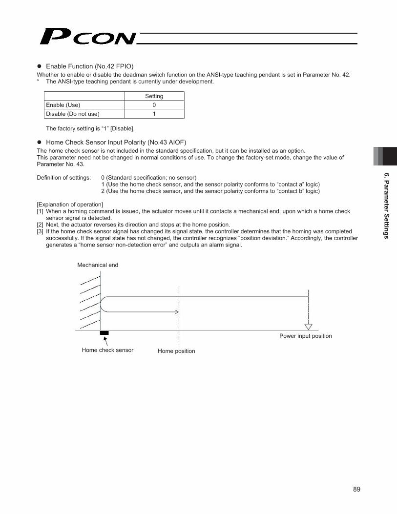
89
6. Parameter Settings
� Enable Function (No.42 FPIO) Whether to enable or disable the deadman switch function on the ANSI-type teaching pendant is set in Parameter No. 42. * The ANSI-type teaching pendant is currently under development.
Setting Enable (Use) 0Disable (Do not use) 1
The factory setting is “1” [Disable].
� Home Check Sensor Input Polarity (No.43 AIOF) The home check sensor is not included in the standard specification, but it can be installed as an option. This parameter need not be changed in normal conditions of use. To change the factory-set mode, change the value of Parameter No. 43.
Definition of settings: 0 (Standard specification; no sensor) 1 (Use the home check sensor, and the sensor polarity conforms to “contact a” logic) 2 (Use the home check sensor, and the sensor polarity conforms to “contact b” logic)
[Explanation of operation] [1] When a homing command is issued, the actuator moves until it contacts a mechanical end, upon which a home check
sensor signal is detected. [2] Next, the actuator reverses its direction and stops at the home position. [3] If the home check sensor signal has changed its signal state, the controller determines that the homing was completed
successfully. If the signal state has not changed, the controller recognizes “position deviation.” Accordingly, the controller generates a “home sensor non-detection error” and outputs an alarm signal.
Mechanical end
Power input position
Home position Home check sensor

90
6. P
aram
eter
Set
tings
� Home Sensor Input Polarity (No. 18, LS) This parameter is supported by the rotational axes of RCP2-RTB/RTC types adopting the home sensor method. Definition of settings: 0 (Sensor not used)
1 (Sensor polarity of contact a) 2 (Sensor polarity of contact b)
� Ball Screw Lead (No. 77, LEAD) This parameter defines the ball screw lead. Before shipment, a default value appropriate for the actuator characteristics is set.
� Axis Operation Type (No. 78, ATYP) This parameter defines the type of the actuator used. Definition of settings: 0 (Linear axis)
1 (Rotational axis)
� Rotational Axis Mode Selection (No. 79, ATYP) If the axis operation type (No. 78) is set to “Rotational axis,” selecting the index mode fixes the current value to within a range of 0 to 359.99. If the index mode is selected, short-cut control is enabled. Definition of settings: 0 (Normal mode)
1 (Index mode)
Note: Push-motion operation cannot be performed in the index mode. Even if data is set in the “Push” field of the position data, in the index mode the data becomes invalid and the actuator moves as normal. Also in the index mode, the positioning band corresponds to the default positioning band set by a parameter.

91
6. Parameter Settings
� Shortcut Selection for Rotational Axis (No. 80, ATYP) This parameter is set in certain conditions, such as when you want to turn a rotational axis in a specific direction. Shortcut refers to operating an actuator in such a way that it always moves to a point that is closest to the next point.
Setting Do not select 0Select 1
You can cause the actuator to rotate in a specific direction by selecting the shortcut mode.
If the actuator is to be moved in the sequence of 1 → 2 → 3 → 4, the specific operation will vary depending on whether or not the shortcut mode is selected, as shown below.
Shortcut mode is not selected
Shortcut mode is selected
� Absolute Unit (No. 83, ETYP) Parameter No. 83 sets whether or not to use the optional simple absolute unit.
Setting Do not use 0Use 1
Positions
Point No. Setting1 0 2 90 3 180 4 270
As for position data, 1° corresponds to 1 mm.
Point No. 1
Point No. 1
Point No. 2
Point No. 3
Point No. 4
Point No. 2
Point No. 3
Point No. 2
Point No. 3
Point No. 4 Point No. 4
Point No. 1
Point No. 1
Point No. 2
Point No. 3
Point No. 2
Point No. 3
Point No. 4 Point No. 4
Point No. 1

92
6. P
aram
eter
Set
tings
6.2.3 Parameters Relating to External Interface
� PIO Pattern Selection (No.25 IOPN) Parameter No. 25 is used to select a desired PIO operation pattern. This is a basic operation parameter, so be sure to set it at the beginning.
Setting of Parameter No. 25 Features of PIO pattern
0 Proximity switch type Each movement complete signal is handled in the same manner as an auto switch of an air cylinder.A movement complete signal is output as the actuator passes the applicable position, even when positioning is not performed. A ready output signal is provided, but no zone output signal is available.
1 Standard type A movement complete signal is output upon completion of positioning following a move command. A zone output signal is provided, but no ready output signal is available.
The factory setting is “0” [Proximity switch type].
� Positioning Complete Signal Output Mode (No.39FPIO) This parameter defines the positioning complete signal state to be applied when the servo turns off or “position deviation” occurs while the actuator is standing still after completion of positioning in the standard type. The following two scenarios can be considered: [1] The actuator position has deviated beyond the value set in the “Positioning band” field of the position table, due to external
force applied while the servo was on. [2] The actuator position has deviated beyond the value set in the “Positioning band” field of the position table, due to external
force applied while the servo was off. This parameter provides flexibility as to how the “positioning complete signal state” is monitored in accordance with the characteristics of the applicable system or sequence circuit of the PLC. The table below shows how the ON/OFF state of a positioning complete signal changes in accordance with each setting of Parameter No. 39.
Setting of Parameter No. 39
Definition of rear end complete (PE0), front end complete (PE1), and intermediate point complete (PE2) signal state
0 [PEND] [1] When the servo is on The signal remains ON even when the current position has deviated from the range corresponding to the value set for the target position in the “Positioning band” field of the position table. [2] When the servo is off The signal turns OFF unconditionally regardless of the current position.
1 [INP] Regardless of the servo on/off status, the signal turns ON if the current position is inside the corresponding to the value set for the target position in the “Positioning band” field of the position table, and turns OFF if it the current position is outside the range. * The signal effectively functions in the same manner as an auto switch of an air cylinder.
The factory setting is “0” [PEND].

93
6. Parameter Settings
� Servo-on Input Disable Selection (No.21 FPIO) Parameter No. 21 is used to set whether enable or disable the servo-on input signal.
Setting Enable (Use) 0Disable (Do not use) 1
The factory setting is “0” [Enable].
� SIO Communication Speed (No.16 BRSL) This parameter is not used with this controller. It applies to controllers of serial communication type. If this parameter is set, it sets the communication speed to be used when the controller implements serial communication control via the PLC’s communication module. Set Parameter No. 16 to a value appropriate for the specification of the communication module. 9600, 19200, 38400 or 115200 bps can be selected as the communication speed. The factory setting is “38400” bps.
� Minimum Delay Time for Slave Transmitter Activation (No.17 RTIM) This parameter is not used with this controller. It applies to controllers of serial communication type. If this parameter is set, it defines the minimum delay before the controller’s transmitter is activated following the completion of command reception, when the controller implements serial communication control via the PLC’s communication module. The factory setting is “5” msec. If the communication module specification exceeds 5 msec, set the required time in Parameter No. 17.
� Silent Interval Multiplication Factor (No.45 SIVM) This parameter is not used with this controller. It applies to RS485 serial communication commands. If this parameter is set, it defines the multiplication factor of silent interval time to be used for delimiter judgment in the RTU mode.The factory setting is the communication time corresponding to 3.5 characters in accordance with the Modbus specification. This parameter need not be changed in normal conditions of use where the actuator is operated using a PC or teaching pendant. If the character sending interval exceeds the silent interval because the scan time of the PLC is not ideal, however, you can extend the silent interval time through Parameter No. 45. The minimum setting unit is 1 (times), and the input range is 0 to 10. If “0” is set, it means that the silent interval multiplication factor is disabled.

94
6. P
aram
eter
Set
tings
6.2.4 Servo Gain Adjustment
Since the servo has been adjusted at the factory in accordance with the standard specification of the actuator, the servo gain need not be changed in normal conditions of use. However, vibration or noise may occur depending on how the actuator is affixed, specific load condition, and so on, and therefore the parameters relating to servo adjustment are disclosed to allow the customer to take quick actions should adjustment become necessary. Particularly with custom models (whose ball screw lead or stroke is longer than the that of the standard model), vibration/noisemay occur due to external conditions. In this case, the parameters shown below must be changed. Contact IAI for details.
� Servo Gain Number (No.7 PLG0)
Parameter number Unit Input range Default 7 5 rad/sec 0 ~ 31 6
This parameter determines the level of response with respect to a position control loop. Increasing the setting improves compliance with the position command. However, increasing the setting too much increases the tendency of the actuator to overshoot. If the setting is low, compliance with the position command drops and the positioning time increases as a result.
� Speed Loop Proportional Gain (No.31 VLPG)
Parameter number Unit Input range Default 31 --- 1 ~ 27661 Set individually in accordance with the actuator characteristics.
This parameter determines the level of response with respect to a speed control loop. Increasing the setting improves compliance with the speed command (i.e., servo rigidity increases). The greater the load inertia, the higher the setting should be. However, increasing the setting too much increases the tendency of the actuator to overshoot or oscillate, resulting in increased mechanical vibration.
Speed Setting is high (overshoot)
Setting is low
Time
Speed Setting is high (overshoot)
Setting is low
Time

95
6. Parameter Settings
Speed Loop Integral Gain (No.32 VLPT)
tluafeDegnar tupnI tinU rebmun retemaraP32 --- 1 ~ 217270 Set individually in accordance with the actuator characteristics.
Torque Filter Time Constant (No.33 TRQF)
Parameter number Unit Input range Default 33 --- 1 ~ 2500 Set individually in accordance with the actuator characteristics.
This parameter determines the filter time constant applicable to the torque command. If the mechanical resonance frequency is equal to or lower than the servo loop response frequency, the motor will vibrate.This mechanical resonance can be suppressed by increasing the setting of this parameter.It should be noted, however, that increasing the setting too much may affect the stability of the control system.
This parameter determines the level of response with respect to a speed control loop.Decreasing the setting results in lower response to the speed command and decreases the reactiveforce upon load change. If the setting is too low, compliance with the position command drops and the positioning time increases as a result.Increasing the setting too much increases the tendency of the actuator to overshoot or oscillate, resulting in increased mechanical vibration.
Speed
Setting is low
Setting is high (overshoot)
Time

96
7. T
roub
lesh
ootin
g
7. Troubleshooting
7.1 What to Do When A Problem Occurs If you encountered a problem, follow the steps below to conduct the specified checks to gather information needed to implement quick recovery and prevent recurrence of the problem.
a. Check the status indicator lamps SV (green) --- The servo is on. ALM (red) --- An alarm is present or emergency stop has been actuated, or the motor drive power is cut off.
b. Check the host controller for abnormality. c. Check the voltage of the 24-VDC main power supply. d. Check the voltage of the 24-VDC power supply for I/O signals. e. Check for alarms.
Check the details of each alarm on the PC or teaching pendant. f. Check the cables for miswiring, disconnection and pinching.
Before checking the continuity of cables, turn off the power (to prevent a runaway actuator) and disconnect all wirings (to prevent the power from being supplied unexpectedly due to a sneak path).
g. Check the I/O signals. h. Check the noise elimination measure (ground connection, surge killer installation, etc.). i. Identify how the problem occurred and the operating condition when the problem occurred. j. Check the serial numbers of the controller and actuator. k. Analyze the cause. l. Take an action.
Before contacting IAI, please check the items in a through j above. Provide the information to our technical staff.
(Reference) Changes in indicators and *ALM output signal in each status
Servo off Servo on Emergency stop actuated Motor drive power cut off
SV (lamp) Unlit Lit Unlit UnlitALM (lamp) Unlit Unlit Lit Lit*ALM (signal) OFF OFF ON ON
(Note 2) The *ALM output signal is a contact-b signal. After the power is input, these signals remain ON while the controller is normal. They turn OFF when the power is cut off.These signals cannot be used for providing a contact-b interlock when the power is not supplied to the controller.

97
7. Troubleshooting
7.2 Alarm Level Classification The alarms are classified into three levels based on the corresponding symptoms.
Alarm level ALM lamp *ALM signal Condition at occurrence of alarm How to reset Operation cancellation Lit Output The actuator decelerates to a stop,
and then the servo turns off. Execute reset using the PC/teaching pendant.
Cold start Lit Output The actuator decelerates to a stop, and then the servo turns off. Reconnect the power.
Note: Whatever the alarm, always investigate the cause of the alarm and remove the cause before resetting the alarm. If the cause of the alarm cannot be removed, or when the alarm cannot be reset even after the cause has been removed, please contact IAI. If the same error occurs again after a reset, the cause of the alarm still exists.

98
7. T
roub
lesh
ootin
g
7.3 Alarms, Causes and Actions
(1) Operation Cancellation Alarms
Code Error Cause/action
0A1 Parameter data error Cause: The parameter data does not meet the specified input range. (Example) This alarm generates when a pair of values clearly has an
inappropriate magnitude relationship, such as when the soft limit + setting is 200.3 mm, while the soft limit – setting is 300 mm.
Action: Change the settings to appropriate values.
0A2 Position data error Cause: [1] A move command was input when a target position was not yet set in the “Position” field.
[2] The target position in the “Position” field is outside the soft limit range. [3] A target position was specified as a relative coordinate in the “Position”
field when the proximity switch type was selected. Action: [1] Set a target position first.
[2] Change the target position to a value inside the soft limit range. [3] Specify the target position as an absolute coordinate.
0A7 Command deceleration error
If the target position is near a soft limit and the deceleration setting is low, issuing a command that specifies this position number while the actuator is moving may cause the actuator to overshoot beyond the soft limit.
Cause: When the speed was changed while the actuator was moving, the next move command was not issued quick enough.
Action: Quicken the switching timing so that the actuator will not overshoot beyond the soft limit.
0BA Home sensor not yet detected
This alarm indicates that the actuator equipped with a home check sensor did not complete homing successfully. Cause: [1] The work contacted peripheral equipment during the homing.
[2] The slide resistance of the actuator is large in some areas. [3] The home check sensor is not installed properly, or the sensor is faulty
or its circuit is open. Action: If the work is not contacting any peripheral equipment, [2] and [3] are
suspected. Contact IAI.
0BE Homing timeout Cause: After the start of homing, homing does not complete after elapse of the time set by the manufacturer’s parameter. (This alarm does not generate during normal operation.)
Action: As one possible cause, the controller and actuator combination may be incorrect. Contact IAI.
The soft limit is not exceeded if deceleration is started here. The soft limit is
exceeded if a command is issued here.
Soft limit

99
7. Troubleshooting
Code Error Cause/action
0C0 Excessive actual speed Cause: The motor speed exceeds the maximum speed set by the manufacturer’ sparameter.This alarm does not generate during normal operation, but it may occur if theload decreased before a servo error was detected and the motor speed hasincreased as a result. This condition occurs due to the following reasons:[1] The slide resistance of the actuator is large in some areas.[2] The load increased due to momentary application of external force.
Action: Check the assembly condition of mechanical parts for any abnormality. If theactuator itself is suspected as the cause, contact IAI.
0C1 Servo error This alarm indicates that after the acceptance of the move command, the motor couldnot operate for 2 seconds or more before the actuator reached the target position.Cause: [1] The connector of the motor relay cable is loose or its circuit is open.
[2] If the actuator is equipped with a brake, the brake cannot be released.[3] The load increased due to application of external force.
he actuator itself is high.
Action: [1] Check the wiring condition of the motor relay cable.[2] Check the wiring condition of the brake cable, and also turn on/off the
brake release switch to check if “click” sound is heard.[3] Check the assembly condition of mechanical parts for any abnormality.
check the slide resistance.ted as the cause, contact IAI.
0C9 Excessive motorpower-supply voltage
This alarm indicates that the voltage of the motor power supply is excessive (24 V +20%: 28.8 V or above).Cause: [1] The voltage of the 24-V input power supply is high.
[2] Faulty part in the controllerAction: Check the input power-supply voltage.
If the voltage is normal, contact IAI.
0CA Overheat This alarm indicates that the temperature around the power transistor in the controlleris excessive (95 C or above).Cause: [1] High surrounding temperature
[2] Defective part in the controllerAction: [1] Lower the temperature around the controller.
If the condition in [1] is not applicable, contact IAI.
0CC Excessive controlpower-supply voltage
This alarm indicates that the voltage of the 24-V input power supply is excessive (24 V+ 20%: 28.8 V or above).Cause: [1] The voltage of the 24-V input power supply is high.
[2] Faulty part in the controllerAction: Check the input power-supply voltage.
If the voltage is normal, contact IAI.
[4] The sliding resistance of t[5] The positioning band setting is smaller than the encoder resolution.
[5] Set the positioning band value greater than that of the encoder
[4] If the load is normal, cut off the power and move the actuator by hand to
If the actuator itself is suspec
resolution.

100
7. T
roub
lesh
ootin
g
Code Error Cause/action
0CE Low control power-supply voltage
This alarm indicates that the voltage of the 24-V input power supply is low (24 V - 20%: 19.2 V or below). Cause: [1] The voltage of the 24-V input power supply is low.
[2] Faulty part in the controller Action: Check the input power-supply voltage.
If the voltage is normal, contact IAI.
0D8 Deviation overflow The position deviation counter has overflowed. Cause: [1] The speed dropped while the actuator was moving due to external force,
etc.[2] Unstable excitation detection operation after the power was turned on
Action: [1] Check the load condition, such as whether the work is contacting any peripheral equipment or the brake is released, and remove the cause of the identified problem.
[2] Overload condition is suspected, so check the load.
0D9 Software limit overshoot error
Cause: [1] The actuator installed in vertical configuration overshot and exceeded a soft limit when the target position was near the soft limit and the load was large or the deceleration setting was high.
[2] The actuator was moved to a position outside the soft limits with the servo turned OFF, and then the servo was turned ON.
Action: [1] Set a deceleration curve that will not cause the actuator to overshoot when stopping.
[2] Return the actuator to within the soft limits first, and then turn ON the servo.

101
7. Troubleshooting
(2) Cold Start Alarms
Code Error Cause/action
0B8 Excitation detection error This controller detects the excited phase when the servo is turned on for the first time after turning on the power. This alarm indicates that the specified encoder signal level cannot be detected after excitation for the time set by Parameter No. 29 (Excited phase signal detection time). Cause: [1] The connector of the motor relay cable is loose or its circuit is open.
[2] If the actuator is equipped with a brake, the brake cannot be released. [3] The load increased due to application of external force. [4] The power was turned on when the actuator was contacting a
mechanical end. [5] The sliding resistance of the actuator itself is high.
Action: [1] Check the wiring condition of the motor relay cable. [2] Check the wiring condition of the brake cable, and also turn on/off the
brake release switch to check if “click” sound is heard. [3] Check the assembly condition of mechanical parts for any abnormality.[4] Move the actuator away from the mechanical end, and then turn on the
power again. [5] If the load is normal, cut off the power and move the actuator by hand to
check the slide resistance. If the actuator itself is suspected as the cause, contact IAI.
0E5 Encoder receive error Cause: [1] When the 24-V power is turned on, the controller is powered up before the simple absolute unit.
[2] When the detail code is H’0001: The controller cannot communicate with the simple absolute unit properly due to noise, etc.
[3] When the detail code is H’0002: The controller cannot communicate with the simple absolute unit properly due to disconnection of the communication wire in the encoder cable, etc.
Action: [1] Always turn on the power to the simple absolute unit before (or simultaneously as) the controller power.
[2] Change the installation location of the controller. Implement noise measures such as installing a FG, noise filter or clamp filter.
[3] Check the encoder relay cable between the controller and simple absolute unit for a loose connector or connectors. If both connectors on the cable are engaged properly, replace the cable.
0E8 Open phase A/B detected Encoder signals cannot be detected correctly.
0E9 Open phase A detected
0EA Open phase B detected
Cause: [1] The connector of the encoder relay cable is loose or its circuit is open. [2] The connector of the supplied actuator cable is loose or its circuit is
open. Action: Check the connection condition of the encoder relay cable and perform
continuity check. If no abnormality is found, contact IAI.

102
7. T
roub
lesh
ootin
g
Code Error Cause/action
0ED Absolute encoder error (1) Cause: [1] When the power was turned off and then on again following an absolute reset, the current position changed due to an external factor, etc., while the controller was communicating with the absolute unit.
[2] When an absolute reset was executed, the current position changed due to an external factor, etc., while the controller was communicating with the absolute unit.
Action: [1] When the detail code is H’0001: Turn off the power and then turn it back on in a condition where the actuator is not receiving vibration, etc.
[2] When the detail code is H’0002: Perform homing again in a condition where the actuator is not receiving vibration, etc.
0EE Absolute encoder error (2) Cause: [1] The power has been turned on for the first time after the battery was connected to the simple absolute unit.
[2] When the detail code is H’0001: The battery voltage has dropped to a level where the encoder counter in the simple absolute unit can no longer retain data.
[3] When the detail code is H’0002: The encoder connector was unplugged during a power outage, or the encoder cable became disconnected.
[4] When the detail code is H’0003: A related parameter was changed.
Action: If [1], [3] or [4] is the case, perform an absolute reset by referring to the operation manual for the simple absolute unit (5.2, “How to Perform an Absolute Reset”). If [2] is the case, supply power for at least 48 hours to fully charge the battery, and then perform an absolute reset.
0EF Absolute encoder error (3) Cause: The current value has changed at a speed corresponding to or exceeding the rotational speed setting, due to an external factor, etc., while the power was cut off.
Action: Change the applicable setting of the simple absolute unit and also implement measures to prevent the actuator from moving at a speed corresponding to or exceeding the set speed while the power is cut off. When the battery has enough retention time, set the motor speed setting high.
Reference: Refer to: 5.1.1, “Piano Switch Settings” in the operation manual for the simple absolute unit. Should this error occur, perform an absolute reset according to the specified procedure (5.2, “How to Perform an Absolute Reset”).

103
7. Troubleshooting
Code Error Cause/action
0F4 Inconsistent PCB This controller uses a different motor drive circuit depending on the motor capacity, and therefore the installed printed circuit board (PCB) is also different with each controller. During the initialization after starting, the controller checks if the motor type set by the manufacturer’s parameter matches the actual PCB installed. This alarm indicates that the two do not match. Cause: The parameter may not be entered correctly or the PCB may not be
assembled correctly. Action: If you have encountered this error, contact IAI.
0F5 Nonvolatile memory verification error after write
When data has been written to the nonvolatile memory, the written data is read and compared (verified) against the written data for confirmation. This alarm indicates that the read data does not match the written data. Cause: [1] Faulty nonvolatile memory
[2] The memory has been rewritten more than 100,000 times. (The nominal life of the nonvolatile memory is 100,000 rewrite operations.)
Action: If the problem still persists after the power has been reconnected, contact IAI.
0F6 Nonvolatile memory timeout after write
This alarm indicates that no response was received within the specified time after writing data to the nonvolatile memory. Cause: [1] Faulty nonvolatile memory
[2] The memory has been rewritten more than 100,000 times. (The nominal life of the nonvolatile memory is 100,000 rewrite operations.)
Action: If the problem still persists after the power has been reconnected, contact IAI.
0F8 Damaged nonvolatile memory
Abnormal data was detected in the nonvolatile memory check after starting. Cause: [1] Faulty nonvolatile memory
[2] The memory has been rewritten more than 100,000 times. (The nominal life of the nonvolatile memory is 100,000 rewrite operations.)
Action: If the problem still persists after the power has been reconnected, contact IAI.
0FA CPU error The CPU is not operating correctly. Cause: [1] Faulty CPU
[2] Malfunction due to noise Action: If the problem still persists after the power has been reconnected, contact
IAI.

104
7. T
roub
lesh
ootin
g
7.4 Messages Displayed during Teaching Pendant Operation This section explains the warning messages that may be displayed while operating the teaching pendant.
Code Message Description
112 Input data error An inappropriate value was input as a user parameter setting. (Example) “9601” was input as the serial communication speed by mistake.
Input an appropriate value again.
113114
Input value too small Input value too large
The input value is under the setting range. The input value is over the setting range. Input an appropriate value again by referring to the actuator specifications and parameter list.
115 Homing not yet complete The current position was written before homing was complete. Perform homing first.
117 No movement data No target position is set under the selected position number. Input a target position first.
11E Inconsistent data pair The magnitude relationship of a pair of data is inappropriate. (Example) The same value is set in both the + and – soft limit parameters. Input appropriate values again.
11F Absolute value too small The minimum travel toward a target position is determined by the lead of the drive system and encoder resolution. This message indicates that the input target position is less than this minimum travel.(Example) If the lead is 20 mm, the encoder resolution is 800 pulses and therefore
the minimum travel is calculated as 0.025 mm/pulse (20 ÷ 800). If 0.02 mm is input as the target position, this message will be displayed.
121 Push search end over The final position in push-motion operation exceeds a soft limit. No harm is done as long as the actuator contacts the work. If it misses the work, however, the actuator will reach the soft limit and this message will be displayed. Change either the target position or positioning band.
122 Multiple axes connected at assignment
An axis number was assigned when multiple axes were connected. Always assign an axis number when only one axis is connected.
180181182183
Axis number change OK Controller initialization OK Home change all clear I/O function changed
This is an operation check message. (It does not indicate misoperation or error.)
202 Emergency stop An emergency stop is currently actuated.
20A Servo OFF during movement The servo ON signal (SON) was turned OFF by the PLC while the actuator was moving. As a result, the servo turned OFF and the actuator stopped.

105
7. Troubleshooting
Code Message Description
20C CSTR-ON during operation A move command signal from the PLC turned ON while the actuator was moving, resulting in redundant move commands.
20E Soft limit over A soft limit was reached.
221 Write inhibited in monitor mode
A position table field or parameter was written in the monitor mode.
223 Operation inhibited in monitor mode
The actuator was moved in the monitor mode.
30130230430530630830A30B
Overrun error (M) Framing error (M) SCIR-QUE OV (M) SCIS-QUE OV (M) R-BF OV Response timeout (M) Packet R-QUE OV Packet S-QUE OV
An error occurred in serial communication with the controller. Cause: [1] Garbage data due to noise [2] Duplicate slave numbers when multiple actuators are controlled via
serial communication Action: [1] Revise the wiring, equipment layout, etc., to eliminate noise. [2] Change the slave numbers to eliminate duplication. If the message persists, please contact IAI.
307 Memory command denied A command was denied in serial communication with the controller.
309 Write address error An indeterminable write address error occurred in serial communication with the controller. These messages do not generate during normal operation. Should either of them occur, record the entire error list before turning off the power. The recorded error list will help us identify the cause of the problem. Also contact IAI.
30C No connected axis The controller axis number cannot be recognized. Cause: [1] The controller is not operating properly.
[2] Only the communication line of the supplied cable (SGA/SGB) is open.
[3] If the SIO converter is used, the link cable is not connected although the converter is receiving 24 V.
[4] When multiple controllers are linked, the ADRS switch is set to the same number by mistake on two or more controllers.
Action: [1] Check if the RDY LED on the controller is lit. If this LED is not lit, the controller is faulty.
[2] If you have a spare teaching pendant, change to the spare teaching pendant. Or, switch to the PC software mode and see if the message will disappear.
[3] Connect all pairs of converter and controller using link cables, and then supply the power.
[4] Set each ADRS switch to a unique number. If the message persists, please contact IAI.

106
7. T
roub
lesh
ootin
g
7.5 Common Problems and Recommended Actions
� I/O Signals Cannot Be Sent or Received to/from the PLC. Cause: [1] The 24-V I/O power supply is connected in reverse polarities.
(In this case, input circuits are not affected, but output circuits will be damaged.) [2] If an output circuit presents this problem, electrical current exceeding the maximum current flowed due to a
large load and a circuit component was damaged. [3] Poor contact at the connector or relay terminal block on the PLC side. [4] The female pins on the flat cable connector are bent outward, thus causing contact failure with the male pins
on the controller connector. Action: Check the connection condition of the power supply and connector, as well as the load on the output side.
If [1] or [2] is suspected, the controller must be replaced. If [4] is likely, the flat cable must be replaced. Either way, contact IAI.
Warning: When checking the continuity of the flat cable, exercise due caution not to bend the female pins on the connector outward. It may cause contact failure, resulting in malfunction.
� The ALM Lamp Illuminates after the Power Is Turned On. (An alarm is present, emergency stop is actuated, or the motor power is cut off.) * If the ALM output signal is OFF, an alarm is present. Connect a PC or teaching pendant to check the nature of the error
and remove the cause. * If the ALM output signal is ON, the emergency stop circuit is actuated. Check the following items: [1] Is the emergency stop switch on the operation panel pressed by mistake? Is the necessary interlock canceled? [2] Is the emergency stop switch on the teaching pendant pressed by mistake? [3] Is Parameter No. 42 (Enable function) enabled by mistake when a teaching pendant is connected that does not support
the enable switch? [4] If multiple controllers are linked together, are they wired correctly?
� After Turning On the Power, the SV Lamp Does Not Illuminate upon Servo-on Signal Input. (The Servo Does Not Turn On.) Cause: [1] Contact failure of the flat cable
[2] Faulty controller Check the servo-on signal (SON) in the I/O monitor screen on the PC or teaching pendant. If the signal is input, the controller may be faulty. Contact IAI.

107
7. Troubleshooting
� With an Actuator Installed in Vertical Orientation, Positioning Completes Prematurely. Cause: [1] The load exceeds the rated load capacity.
[2] The ball screw is receiving torsional stress due to the actuator affixing method, uneven tightening of bolts, etc.
[3] The slide resistance of the actuator itself is high. Action: If [1] is suspected, increase the value of User Parameter No. 13 (Current-limiting value during homing).
Increasing the parameter value increases the homing torque. As a guide, however, the setting should not exceed 100% for the RA3C/RGD3C types or 75% for all other types. [2] To check if the condition in [2] is present, loosen the affixing bolts and check if the slider moves smoothly. If
the slider moves smoothly, adjust the affixing method and bolt tightening method. [3] If the slide resistance of the actuator itself is high, contact IAI.
� With an Actuator Installed in Vertical Orientation, Noise Generates during Downward Movement. Cause: The load exceeds the rated load capacity. Action: [1] Decrease the speed.
[2] Decrease the value set in User Parameter No. 7 (Servo gain number). As a guide, do not decrease the setting to below 3.
� Vibration Occurs when the Actuator Is at Standstill. Cause: The slider is receiving external force. Action: If external force cannot be removed, increase the value set in User Parameter No. 12 (Current-limiting value at
standstill after positioning). Increasing the setting of this parameter increases the holding torque. As a guide, keep the current limiting value to 70% or below.
� The Actuator Overshoots while Decelerating to a Stop. Cause: The load inertia is high due to an inappropriate balance of the load and deceleration. Action: Decrease the set deceleration.
� Stopped Position Sometime Deviates from the Home Position or Target Position. Cause: [1] Encoder waveforms are disturbed due to noise.
[2] If the actuator is of rod type, non-rotational error increased due to application of rotational moment to the rod.
Action: [1] Check if the grounding is provided correctly, and also check for any equipment that may be generating noise.
[2] Depending on the condition, the actuator may have to be replaced. Contact IAI.
� The Actuator Moves Slow during Push-motion Operation. Cause: The set current-limiting value is low with respect to the load and slide resistance. Action: Increase the current-limiting value during push-motion operation.
� The Actuator Moves Only a Half, or as Much as Twice, the Specified Travel. Cause: [1] The controller and actuator combination is incorrect.
The ball screw lead varies according to the actuator type. If the actuator is not combined with an appropriate controller, the travel and speed will change.
[2] Pre-shipment setting error at IAI Action: [1] If multiple actuators of different types are used, check the label on each actuator or use other means to see
if they are connected to correct controllers. [2] Contact IAI.

108
7. T
roub
lesh
ootin
g
� A Servo Error Occurred while the ROBO Gripper Was Moving. Cause: The work was not positioned properly and a finger attachment contacted the work in the positioning mode. Action: Consider how much the work deviates and adjust the start position of push-motion operation, as well as the
thickness of the finger attachment (including buffer material), so that the work can be clamped properly in the push-motion mode. Before resetting the error, be sure to turn the open/close screw and loosen the finger attachments first, because the feed mechanism may be locked.
Caution: If the alarm is reset when the servo-on signal is disabled or while the servo-on signal is ON, the servo will turn on. Turning the open/close screw in this condition only results in the screw returning to the original position, and the feed mechanism remains locked. Therefore, the alarm will generate again the next time a move command is issued.
[Two-finger type]
[Three-finger type] Remove one of the finger attachments and take out the work, and then turn the open/close screw clockwise.
OP
EN
Open/close screw Turn counterclockwise using a flat-head screwdriver.
Remove one of the finger attachments.
Open/close screw
Opening direction
Turn clockwise.

109
7. Troubleshooting
� The Actuator Malfunctions when the Servo Is Turned On after Turning On the Power. Cause: Excited phase detection is not performed properly when the servo is turned on, because one of the following
conditions exists when the power was turned on: [1] The slider or rod was contacting a mechanical end. [2] The work was pushed by a strong external force.
Action: [1] Check if the slider or rod is not contacting a mechanical end. If the slider/rod is contacting a mechanical end, separate the slider/rod from the mechanical end. If the actuator is equipped with a brake, turn on the brake release switch to forcibly release the brake before moving the actuator. At this time, be careful not to pinch your hand or damage the robot hand or work by the slider/rod, as the slider/rod may drop unexpectedly by its dead weight. If the actuator cannot be moved by hand, one measure is to check the direction of excited phase signal detection and change the direction of detection as necessary. If you wish to change the direction, contact IAI beforehand. For details, refer to the applicable parameter explained in 6.2.2, “Parameters Relating to Actuator Operating Characteristics.”
[2] Check if the work is not contacting any peripheral equipment. If the work is contacting peripheral equipment, separate the work from the equipment by providing a minimum clearance of 1 mm in between.
If neither [1] nor [2] applies, contact IAI. � The SV Lamp Blinks.
The automatic servo-off mode is active. (This is not an error or failure.)
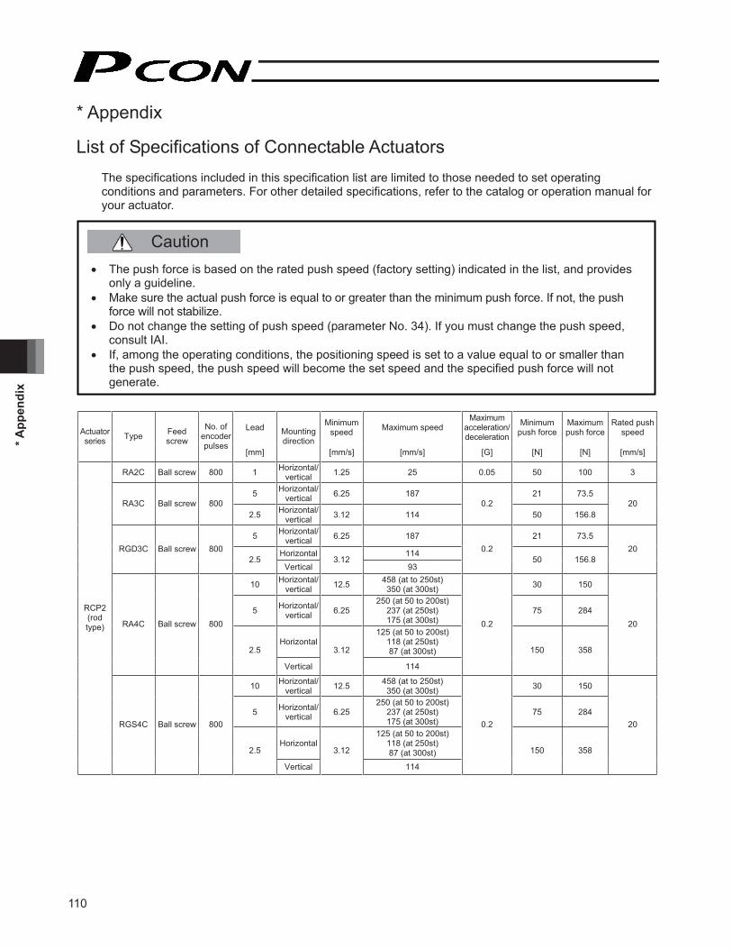
110
* App
endi
x
* Appendix
List of Specifications of Connectable Actuators The specifications included in this specification list are limited to those needed to set operating conditions and parameters. For other detailed specifications, refer to the catalog or operation manual for your actuator.
Lead Minimumspeed Maximum speed
Maximum acceleration/deceleration
Minimumpush force
Maximum push force
Rated push speedActuator
series Type Feedscrew
No. of encoder pulses
[mm]
Mounting direction
[mm/s] [mm/s] [G] [N] [N] [mm/s]
RA2C Ball screw 800 1 Horizontal/vertical 1.25 25 0.05 50 100 3
5 Horizontal/vertical 6.25 187 21 73.5
RA3C Ball screw 800 2.5 Horizontal/
vertical 3.12 114 0.2
50 156.8 20
5 Horizontal/vertical 6.25 187 21 73.5
Horizontal 114 RGD3C Ball screw 800 2.5
Vertical3.12
93
0.250 156.8
20
10 Horizontal/vertical 12.5 458 (at to 250st)
350 (at 300st) 30 150
5 Horizontal/vertical 6.25
250 (at 50 to 200st) 237 (at 250st) 175 (at 300st)
75 284
Horizontal125 (at 50 to 200st)
118 (at 250st) 87 (at 300st)
RA4C Ball screw 800
2.5
Vertical
3.12
114
0.2
150 358
20
10 Horizontal/vertical 12.5 458 (at to 250st)
350 (at 300st) 30 150
5 Horizontal/vertical 6.25
250 (at 50 to 200st) 237 (at 250st) 175 (at 300st)
75 284
Horizontal125 (at 50 to 200st)
118 (at 250st) 87 (at 300st)
RCP2(rodtype)
RGS4C Ball screw 800
2.5
Vertical
3.12
114
0.2
150 358
20
� The push force is based on the rated push speed (factory setting) indicated in the list, and provides only a guideline.
� Make sure the actual push force is equal to or greater than the minimum push force. If not, the push force will not stabilize.
� Do not change the setting of push speed (parameter No. 34). If you must change the push speed, consult IAI.
� If, among the operating conditions, the positioning speed is set to a value equal to or smaller than the push speed, the push speed will become the set speed and the specified push force will not generate.
Caution

111
* Appendix
Lead Minimumspeed Maximum speed
Maximum acceleration/deceleration
Minimumpush force
Maximum push force
Rated push speedActuator
series Type Feedscrew
No. of encoder pulses
[mm]
Mounting direction
[mm/s] [mm/s] [G] [N] [N] [mm/s]
10 Horizontal/vertical 12.5 458 (at to 250st)
350 (at 300st) 30 150
5 Horizontal/vertical 6.25
250 (at 50 to 200st) 237 (at 250st) 175 (at 300st)
75 284
Horizontal125 (at 50 to 200st)
118 (at 250st) 87 (at 300st)
RGD4C Ball screw 800
2.5
Vertical
3.12
114
0.2
150 358
20
Horizontal 450 16
Vertical20
40075 240
8 Horizontal/vertical 10 210 130 470 RA6C Ball screw 800
4 Horizontal/vertical 5 130
0.2
300 800
20
Horizontal 450 16
Vertical20
40075 240
8 Horizontal/vertical 10 210 130 470 RGS6C Ball screw 800
4 Horizontal/vertical 5 130
0.2
300 800
20
Horizontal 450 16
Vertical20
40075 240
8 Horizontal/vertical 10 210 130 470 RGD6C Ball screw 800
4 Horizontal/vertical 5 130
0.2
300 800
20
5 Horizontal/vertical 6.25 250 0.3 26 90
Horizontal 124 SRA4R Ball screw 800 2.5
Vertical3.12
1250.2 50 170
20
5 Horizontal/vertical 6.25 250 0.3 26 90
Horizontal 124 SRGS4R Ball screw 800 2.5
Vertical3.12
1250.2 50 170
20
5 Horizontal/vertical 6.25 250 0.3 26 90
Horizontal 124
RCP2(rodtype)
SRGD4R Ball screw 800 2.5
Vertical3.12
1250.2 50 170
20

112
* App
endi
x
Lead Minimumspeed Maximum speed
Maximum acceleration/deceleration
Minimumpush force
Maximum push force
Rated push speedActuator
series Type Feedscrew
No. of encoder pulses
[mm]
Mounting direction
[mm/s] [mm/s] [G] [N] [N] [mm/s]
Horizontal
380 (at 50st) 540 (at 100st) 660 (at 150st) 770 (at 200st) 860 (at 250st) 940 (at 300st)
1000 (at 350 to 550st)980 (at 600st) 850 (at 650st) 740 (at 700st) 650 (at 750st) 580 (at 800st)
0.7
20
Vertical
25
380 (at 50st) 540 (at 100st) 660 (at 150st) 770 (at 200st)
800 (at 250 to 600st) 740 (at 700st) 650 (at 750st) 580 (at 800st)
0.2
11 39
Horizontal 0.7
12
Vertical
15
300 (at 50st) 460 (at 100st)
600 (at 150 to 550st) 540 (at 600st) 460 (at 650st) 400 (at 700st) 360 (at 750st) 300 (at 800st)
0.3
40 115
Horizontal 0.7
6
Vertical
7.5
295 (at 50st) 300 (at 100 to 550st)
270 (at 600st) 230 (at 650st) 200 (at 700st) 180 (at 750st) 150 (at 800st)
0.3
70 210
Horizontal 0.7
SA5C Ball screw 800
3
Vertical
3.75
150 (at to 550st) 135 (at 600st) 115 (at 650st) 100 (at 700st) 90 (at 750st) 75 (at 800st)
0.3
140 330
20
Horizontal 0.3
12
Vertical
15
300 (at 50st) 460 (at 100st)
600 (at 150 to 550st) 540 (at 600st) 460 (at 650st) 400 (at 700st) 360 (at 750st) 300 (at 800st)
0.2
– – –
Horizontal 0.3
6
Vertical
7.5
295 (at 50st) 300 (at 100 to 550st)
270 (at 600st) 230 (at 650st) 200 (at 700st) 180 (at 750st) 150 (at 800st)
0.2
– – –
Horizontal 0.2
RCP2(slider type)
SA5R Ball screw 800
3
Vertical
3.75
150 (at to 550st) 135 (at 600st) 115 (at 650st) 100 (at 700st) 90 (at 750st) 75 (at 800st)
0.2
– – –

113
* Appendix
Lead Minimumspeed Maximum speed
Maximum acceleration/deceleration
Minimumpush force
Maximum push force
Rated push speedActuator
series Type Feedscrew
No. of encoder pulses
[mm]
Mounting direction
[mm/s] [mm/s] [G] [N] [N] [mm/s]
Horizontal
380 (at 50st) 540 (at 100st) 660 (at 150st) 770 (at 200st) 860 (at 250st) 940 (at 300st)
1000 (at 350 to 550st)980 (at 600st) 850 (at 650st) 740 (at 700st) 650 (at 750st) 580 (at 800st)
0.7
20
Vertical
25
380 (at 50st) 540 (at 100st) 660 (at 150st) 770 (at 200st)
800 (at 250 to 600st) 740 (at 700st) 650 (at 750st) 580 (at 800st)
0.2
11 39
Horizontal 0.7
12
Vertical
15
300 (at 50st) 460 (at 100st)
600 (at 150 to 550st) 540 (at 600st) 460 (at 650st) 400 (at 700st) 360 (at 750st) 300 (at 800st)
0.3
40 115
Horizontal 0.7
6
Vertical
7.5
295 (at 50st) 300 (at 100 to 550st)
270 (at 600st) 230 (at 650st) 200 (at 700st) 180 (at 750st) 150 (at 800st)
0.3
70 210
Horizontal 0.7
SA6C Ball screw 800
3
Vertical
3.75
150 (at to 550st) 135 (at 600st) 115 (at 650st) 100 (at 700st) 90 (at 750st) 75 (at 800st)
0.3
140 330
20
Horizontal 0.3
12
Vertical
15
300 (at 50st) 460 (at 100st)
600 (at 150 to 550st) 540 (at 600st) 460 (at 650st) 400 (at 700st) 360 (at 750st) 300 (at 800st)
0.2
– – –
Horizontal 0.3
6
Vertical
7.5
295 (at 50st) 300 (at 100 to 550st)
270 (at 600st) 230 (at 650st) 200 (at 700st) 180 (at 750st) 150 (at 800st)
0.2
– – –
Horizontal 0.2
RCP2(slider type)
SA6R Ball screw 800
3
Vertical
3.75
150 (at to 550st) 135 (at 600st) 115 (at 650st) 100 (at 700st) 90 (at 750st) 75 (at 800st)
0.2
– – –
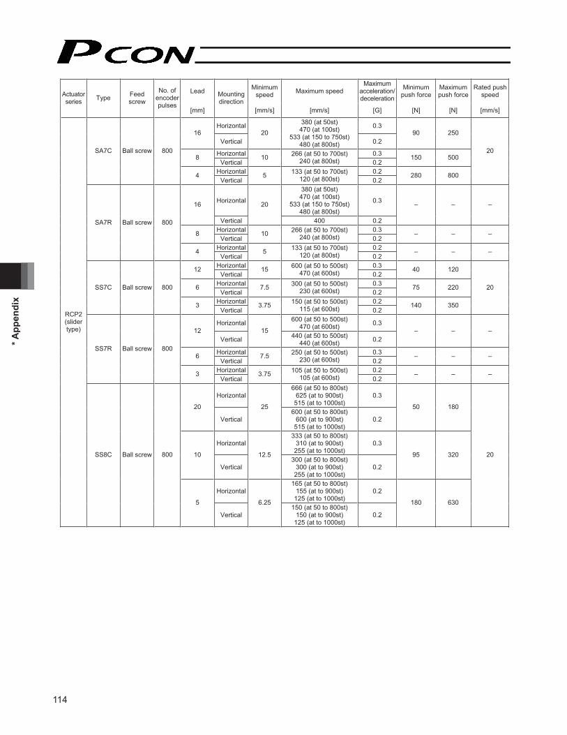
114
* App
endi
x
Lead Minimumspeed Maximum speed
Maximum acceleration/deceleration
Minimumpush force
Maximum push force
Rated push speedActuator
series Type Feedscrew
No. of encoder pulses
[mm]
Mounting direction
[mm/s] [mm/s] [G] [N] [N] [mm/s]
Horizontal 0.3 16
Vertical20
380 (at 50st) 470 (at 100st)
533 (at 150 to 750st) 480 (at 800st) 0.2
90 250
Horizontal 0.3 8Vertical
10 266 (at 50 to 700st) 240 (at 800st) 0.2
150 500
Horizontal 0.2
SA7C Ball screw 800
4Vertical
5 133 (at 50 to 700st) 120 (at 800st) 0.2
280 800
20
Horizontal
380 (at 50st) 470 (at 100st)
533 (at 150 to 750st) 480 (at 800st)
0.316
Vertical
20
400 0.2
– – –
Horizontal 0.3 8Vertical
10 266 (at 50 to 700st) 240 (at 800st) 0.2
– – –
Horizontal 0.2
SA7R Ball screw 800
4Vertical
5 133 (at 50 to 700st) 120 (at 800st) 0.2
– – –
Horizontal 0.3 12Vertical
15 600 (at 50 to 500st) 470 (at 600st) 0.2
40 120
Horizontal 0.3 6Vertical
7.5 300 (at 50 to 500st) 230 (at 600st) 0.2
75 220
Horizontal 0.2
SS7C Ball screw 800
3Vertical
3.75 150 (at 50 to 500st) 115 (at 600st) 0.2
140 350
20
Horizontal 600 (at 50 to 500st) 470 (at 600st) 0.3
12Vertical
15440 (at 50 to 500st)
440 (at 600st) 0.2– – –
Horizontal 0.3 6Vertical
7.5 250 (at 50 to 500st) 230 (at 600st) 0.2
– – –
Horizontal 0.2
SS7R Ball screw 800
3Vertical
3.75 105 (at 50 to 500st) 105 (at 600st) 0.2
– – –
Horizontal666 (at 50 to 800st)
625 (at to 900st) 515 (at to 1000st)
0.3
20
Vertical
25600 (at 50 to 800st)
600 (at to 900st) 515 (at to 1000st)
0.2
50 180
Horizontal333 (at 50 to 800st)
310 (at to 900st) 255 (at to 1000st)
0.3
10
Vertical
12.5300 (at 50 to 800st)
300 (at to 900st) 255 (at to 1000st)
0.2
95 320
Horizontal165 (at 50 to 800st)
155 (at to 900st) 125 (at to 1000st)
0.2
RCP2(slider type)
SS8C Ball screw 800
5
Vertical
6.25150 (at 50 to 800st)
150 (at to 900st) 125 (at to 1000st)
0.2
180 630
20

115
* Appendix
Lead Minimumspeed Maximum speed
Maximum acceleration/deceleration
Minimumpush force
Maximum push force
Rated push speedActuator
series Type Feedscrew
No. of encoder pulses
[mm]
Mounting direction
[mm/s] [mm/s] [G] [N] [N] [mm/s]
Horizontal600 (at 50 to 800st)
600 (at to 900st) 515 (at to 1000st)
0.3
20
Vertical
25333 (at 50 to 800st)
333 (at to 900st) 333 (at to 1000st)
0.2
– – –
Horizontal300 (at 50 to 800st)
300 (at to 900st) 255 (at to 1000st)
0.3
10
Vertical
12.5250 (at 50 to 800st)
250 (at to 900st) 250 (at to 1000st)
0.2
– – –
Horizontal160 (at 50 to 800st)
155 (at to 900st) 125 (at to 1000st)
0.2
SS8R Ball screw 800
5
Vertical
6.25140 (at 50 to 800st)
140 (at to 900st) 140 (at to 1000st)
0.2
– – –
Horizontal1200 (at 50 to 800st)
1000 (at to 900st) 800 (at to 1000st)
0.3
HS8C Ball screw 800 30
Vertical
37.5750 (at 50 to 800st)
750 (at to 900st) 750 (at to 1000st)
0.2
– – –
Horizontal1200 (at 50 to 800st)
1000 (at to 900st) 800 (at to 1000st)
0.3
RCP2(slider type)
HS8R Ball screw 800 30
Vertical
37.5750 (at 50 to 800st)
750 (at to 900st) 750 (at to 1000st)
0.2
– – –
BA6/BA6U Belt 800 Equivalent
to 54 Horizontal 67.5 1000 0.5 – – – RCP2(belttype) BA7/
BA7U Belt 800 Equivalent to 54 Horizontal 67.5 1500 0.5 – – –
GRSS – 800 1.57 – 1.96 78 – 4 14 20 GRLS – 800 12 – 15 (deg/s) 600 (deg/s) – 1.8 6.4 5 (deg/s)GRS – 800 1 – 1.25 33.3 – 9 21 5 GRM – 800 1.1 – 1.37 36.7 – 23 80 5
– 800 1.05 – 1.31 34 – 15 40 5 GRST– 800 2.27 – 2.83 75 – 7.5 20 5
GR3LS – 800 12 – 15 200 – 5 18 5 (deg/s)GR3LM – 800 12 – 15 200 – 15 51 5 (deg/s)GR3SS – 800 2.5 – 3.12 40 – 7 22 5 GR3SM – 800 3 – 3.75 50 – 30 102 5 GRHM – 800 2 – 2.5 100 – 25 125 5
RCP2(gripper
type)
GRHB – 800 2 – 2.5 100 – 60 200 5

116
* App
endi
x
Lead Minimumspeed Maximum speed
Maximum acceleration/deceleration
Minimumpush force
Maximum push force
Rated push speedActuator
series Type Feedscrew
No. of encoder pulses
[mm]
Mounting direction
[mm/s] [mm/s] [G] [N] [N] [mm/s]
– Gear ratio: 1/30 – 15 (deg/s) 400 (deg/s) – – – –
RTBS–
800Gear ratio:
1/45 – 10 (deg/s) 266 (deg/s) – – – –
– Gear ratio: 1/30 – 15 (deg/s) 400 (deg/s) – – – –
RTBSL–
800Gear ratio:
1/45 – 10 (deg/s) 266 (deg/s) – – – –
– Gear ratio: 1/30 – 15 (deg/s) 400 (deg/s) – – – –
RTCS–
800Gear ratio:
1/45 – 10 (deg/s) 266 (deg/s) – – – –
– Gear ratio: 1/30 – 15 (deg/s) 400 (deg/s) – – – –
RTCSL–
800Gear ratio:
1/45 – 10 (deg/s) 266 (deg/s) – – – –
– Gear ratio: 1/20 – 22.5
(deg/s) 600 (deg/s) – – – – RTB
–800
Gear ratio: 1/30 – 15 (deg/s) 400 (deg/s) – – – –
– Gear ratio: 1/20 – 22.5
(deg/s) 600 (deg/s) – – – – RTBL
–800
Gear ratio: 1/30 – 15 (deg/s) 400 (deg/s) – – – –
– Gear ratio: 1/20 – 22.5
(deg/s) 600 (deg/s) – – – – RTC
–800
Gear ratio: 1/30 – 15 (deg/s) 400 (deg/s) – – – –
– Gear ratio: 1/20 – 22.5
(deg/s) 600 (deg/s) – – – – RTCL
–800
Gear ratio: 1/30 – 15 (deg/s) 400 (deg/s) – – – –
– Gear ratio: 1/20 – 22.5
(deg/s) 600 (deg/s) – – – – RTBB
–800
Gear ratio: 1/30 – 15 (deg/s) 400 (deg/s) – – – –
– Gear ratio: 1/20 – 22.5
(deg/s) 600 (deg/s) – – – – RTBBL
–800
Gear ratio: 1/30 – 15 (deg/s) 400 (deg/s) – – – –
– Gear ratio: 1/20 – 22.5
(deg/s) 600 (deg/s) – – – – RTCB
–800
Gear ratio: 1/30 – 15 (deg/s) 400 (deg/s) – – – –
– Gear ratio: 1/20 – 22.5
(deg/s) 600 (deg/s) – – – –
RCP2(rotary type)
RTCBL–
800Gear ratio:
1/30 – 15 (deg/s) 400 (deg/s) – – – –

117
* Appendix
Lead Minimumspeed Maximum speed
Maximum acceleration/deceleration
Minimumpush force
Maximum push force
Rated push speedActuator
series Type Feedscrew
No. of encoder pulses
[mm]
Mounting direction
[mm/s] [mm/s] [G] [N] [N] [mm/s]
4 5 180 (at 25st) 200 (at 50 to 100st) 0.9 16.1
2 2.5 100 1.9 28.3 RA2AC Leadscrew 800
1
Horizontal/vertical
1.25 50
0.2
3.8 39.5
5
6 7.5180 (at 25st) 280 (at 50st)
300 (at 75 to 150st) 0.6 11.9
4 5 180 (at 25st) 200 (at 50 to 150st) 0.9 16.1
RA2BC Leadscrew 800
2
Horizontal/vertical
2.5 100
0.2
1.9 28.3
5
4 5 180 (at 25st) 200 (at 50 to 150st) 0.9 16.1
2 2.5 100 1.9 28.3 RA2AR Leadscrew 800
1
Horizontal/vertical
1.25 50
0.2
3.8 39.5
5
6 7.5180 (at 25st) 280 (at 50st)
300 (at 75 to 150st) 0.6 11.9
4 5 180 (at 25st) 200 (at 50 to 150st) 0.9 16.1
RCP3(rodtype)
RA2BR Leadscrew 800
2
Horizontal/vertical
2.5 100
0.2
1.9 28.3
5
4 5 180 (at 25st) 200 (at 50 to 100st)
2 2.5 100 SA2AC Leadscrew 800
1
Horizontal
1.25 50
0.2 – – –
6 7.5180 (at 25st) 280 (at 50st)
300 (at 75 to 150st)
4 5 180 (at 25st) 200 (at 50 to 150st)
SA2BC Leadscrew 800
2
Horizontal
2.5 100
0.2 – – –
4 5 180 (at 25st) 200 (at 50 to 100st)
2 2.5 100 SA2AR Leadscrew 800
1
Horizontal
1.25 50
0.2 – – –
6 7.5180 (at 25st) 280 (at 50st)
300 (at 75 to 150st)
4 5 180 (at 25st) 200 (at 50 to 150st)
SA2BR Leadscrew 800
2
Horizontal
2.5 100
0.2 – – –
Horizontal 0.3 6Vertical
7.5 300 0.2
9 15
Horizontal 0.3 4Vertical
5 200 0.2
14 22
Horizontal 0.2
SA3C Ball screw 800
2Vertical
2.5 100 0.2
27 44
20
Horizontal 0.3 6Vertical
7.5 300 0.2
9 15
Horizontal 0.3 4Vertical
5 200 0.2
14 22
Horizontal 0.2
RCP3(slider type)
SA3R Ball screw 800
2Vertical
2.5 100 0.2
27 44
–

118
* App
endi
x
Lead Minimumspeed Maximum speed
Maximum acceleration/deceleration
Minimumpush force
Maximum push force
Rated push speedActuator
series Type Feedscrew
No. of encoder pulses
[mm]
Mounting direction
[mm/s] [mm/s] [G] [N] [N] [mm/s]
Horizontal 0.7 10Vertical
12.5 380 (at 50st) 500 (at 100st to 500st) 0.3
20 34
Horizontal 0.7 5Vertical
6.25 250 0.3
40 68
Horizontal 0.7
SA4C Ball screw 800
2.5Vertical
3.12 125 0.3
82 136
20
Horizontal 0.3 10Vertical
12.5 380 (at 50st) 500 (at 100st to 500st) 0.2
20 34
Horizontal 0.3 5Vertical
6.25 250 0.2
40 68
Horizontal 0.2
SA4R Ball screw 800
2.5Vertical
3.12 125 0.2
82 136
–
Horizontal
380 (at 50st) 540 (at 100st) 660 (at 150st) 770 (at 200st) 860 (at 250st) 940 (at 300st)
1000 (at 350 to 600st)910 (at 650st) 790 (at 700st) 690 (at 750st) 610 (at 800st)
0.7
20
Vertical
25
380 (at 50st) 540 (at 100st) 660 (at 150st) 770 (at 200st)
800 (at 250 to 650st) 790 (at 700st) 690 (at 750st) 610 (at 800st)
0.2
17 28
Horizontal 0.7
12
Vertical
15
380 (at 50st) 540 (at 100st)
600 (at 150st to 550st)570 (at 600st) 490 (at 650st) 425 (at 700st) 370 (at 750st) 330 (at 800st)
0.3
28 47
Horizontal 0.7
6
Vertical
7.5
300 (at 50st to 550st) 285 (at 600st) 245 (at 650st) 210 (at 700st) 185 (at 750st) 165 (at 800st)
0.3
57 95
Horizontal 0.7
RCP3(slider type)
SA5C Ball screw 800
3
Vertical
3.75
150 (at 50st to 550st) 140 (at 600st) 120 (at 650st) 105 (at 700st) 90 (at 750st) 80 (at 800st)
0.3
113 189
20

119
* Appendix
Lead Minimumspeed Maximum speed
Maximum acceleration/deceleration
Minimumpush force
Maximum push force
Rated push speedActuator
series Type Feedscrew
No. of encoder pulses
[mm]
Mounting direction
[mm/s] [mm/s] [G] [N] [N] [mm/s]
Horizontal 0.3
12
Vertical
15
380 (at 50st) 540 (at 100st)
600 (at 150st to 550st)570 (at 600st) 490 (at 650st) 425 (at 700st) 370 (at 750st) 330 (at 800st)
0.2
30 47
Horizontal 0.3
6
Vertical
7.5
300 (at 50st to 550st) 285 (at 600st) 245 (at 650st) 210 (at 700st) 185 (at 750st) 165 (at 800st)
0.2
58 95
Horizontal 0.2
SA5R Ball screw 800
3
Vertical
3.75
150 (at 50st to 550st) 140 (at 600st) 120 (at 650st) 105 (at 700st) 90 (at 750st) 80 (at 800st)
0.2
112 189
20
Horizontal
380 (at 50st) 540 (at 100st) 660 (at 150st) 770 (at 200st) 860 (at 250st) 940 (at 300st)
1000 (at 350 to 600st)910 (at 650st) 790 (at 700st) 690 (at 750st) 610 (at 800st)
0.7
20
Vertical
25
380 (at 50st) 540 (at 100st) 660 (at 150st) 770 (at 200st)
800 (at 250 to 650st) 790 (at 700st) 690 (at 750st) 610 (at 800st)
0.2
17 28
Horizontal 0.7
12
Vertical
15
380 (at 50st) 540 (at 100st)
600 (at 150st to 550st)570 (at 600st) 490 (at 650st) 425 (at 700st) 370 (at 750st) 330 (at 800st)
0.3
28 47
Horizontal 0.7
6
Vertical
7.5
300 (at 50st to 550st) 285 (at 600st) 245 (at 650st) 210 (at 700st) 185 (at 750st) 165 (at 800st)
0.3
57 95
Horizontal 0.7
RCP3(slider type)
SA6C Ball screw 800
3
Vertical
3.75
150 (at 50st to 550st) 140 (at 600st) 120 (at 650st) 105 (at 700st) 90 (at 750st) 80 (at 800st)
0.3
113 189
20

120
* App
endi
x
Lead Minimumspeed Maximum speed
Maximum acceleration/deceleration
Minimumpush force
Maximum push force
Rated push speedActuator
series Type Feedscrew
No. of encoder pulses
[mm]
Mounting direction
[mm/s] [mm/s] [G] [N] [N] [mm/s]
Horizontal 0.3
12
Vertical
15
380 (at 50st) 540 (at 100st)
600 (at 150st to 550st)570 (at 600st) 490 (at 650st) 425 (at 700st) 370 (at 750st) 330 (at 800st)
0.2
30 47
Horizontal 0.3
6
Vertical
7.5
300 (at 50st to 550st) 285 (at 600st) 245 (at 650st) 210 (at 700st) 185 (at 750st) 165 (at 800st)
0.2
58 95
Horizontal 0.2
RCP3(slider type)
SA6R Ball screw 800
3
Vertical
3.75
150 (at 50st to 550st) 140 (at 600st) 120 (at 650st) 105 (at 700st) 90 (at 750st) 80 (at 800st)
0.2
112 189
20
Horizontal 300 0.3 6Vertical
7.5200 0.2
5.4 9
Horizontal 200 0.3 4Vertical
5133 0.2
8.4 14
Horizontal 100 0.2
TA3C Ball screw 800
2Vertical
2.567 0.2
16.8 28
20
Horizontal 300 0.3 6Vertical
7.5200 0.2
5.4 9
Horizontal 200 0.3 4Vertical
5133 0.2
8.4 14
Horizontal 100 0.2
TA3R Ball screw 800
2Vertical
2.567 0.2
16.8 28
20
Horizontal 0.3 6Vertical
7.5 300 0.2
9 15
Horizontal 0.3 4Vertical
5 200 0.2
13.2 22
Horizontal 0.2
TA4C Ball screw 800
2Vertical
2.5 100 0.2
26.4 44
20
Horizontal 0.3 6Vertical
7.5 300 0.2
9 15
Horizontal 0.3 4Vertical
5 200 0.2
13.2 22
Horizontal 0.2
TA4R Ball screw 800
2Vertical
2.5 100 0.2
26.4 44
20
Horizontal 465 0.3 10Vertical
12.5400 0.2
20 34
Horizontal 0.3 5Vertical
6.25 250 0.2
40 68
Horizontal 0.2
TA5C Ball screw 800
2.5Vertical
3.12 125 0.2
82 136
20
Horizontal 465 0.3 10Vertical
12.5400 0.2
20 34
Horizontal 0.3 5Vertical
6.25 250 0.2
40 68
Horizontal 0.2
RCP3(table type)
TA5R Ball screw 800
2.5Vertical
3.12 125 0.2
82 136
20

121
* Appendix
Lead Minimumspeed Maximum speed
Maximum acceleration/deceleration
Minimumpush force
Maximum push force
Rated push speedActuator
series Type Feedscrew
No. of encoder pulses
[mm]
Mounting direction
[mm/s] [mm/s] [G] [N] [N] [mm/s]
Horizontal 560 0.3 12Vertical
15500 0.2
30 47
Horizontal 0.3 6Vertical
7.5 300 0.2
58 95
Horizontal 0.2
TA6C Ball screw 800
3Vertical
3.75 150 0.2
112 189
20
Horizontal 560 0.3 12Vertical
15500 0.2
30 47
Horizontal 0.3 6Vertical
7.5 300 0.2
58 95
Horizontal 0.2
TA6R Ball screw 800
3Vertical
3.75 150 0.2
112 189
20
Horizontal 600 0.3 12Vertical
15580 0.2
30 47
Horizontal 0.3 6Vertical
7.5 300 0.2
58 95
Horizontal 0.2
TA7C Ball screw 800
3Vertical
3.75 150 0.2
112 189
20
Horizontal 600 0.3 12Vertical
15580 0.2
30 47
Horizontal 0.3 6Vertical
7.5 300 0.2
58 95
Horizontal 0.2
RCP3(table type)
TA7R Ball screw 800
3Vertical
3.75 150 0.2
112 189
20

122
* App
endi
x
Appendix
Correlation diagram of speed and load capacity for the slider type (motor-straight type)
(Note) In the above graphs, the number after the type code indicates the lead.
Horizontal installation Vertical installation
Hig
h-sp
eed
type
M
ediu
m-s
peed
type
Lo
w-s
peed
type
Speed (mm/sec)
Load
cap
acity
(kg)
Speed (mm/sec)
Load
cap
acity
(kg)
Speed (mm/sec)
Load
cap
acity
(kg)
Speed (mm/sec)
Load
cap
acity
(kg)
Speed (mm/sec)
Load
cap
acity
(kg)
Speed (mm/sec)
Load
cap
acity
(kg)

123
* Appendix
Appendix
Correlation diagram of speed and load capacity for the slider type (motor-reversing type)
(Note) In the above graphs, the number after the type code indicates the lead.
Horizontal installation Vertical installation
Hig
h-sp
eed
type
M
ediu
m-s
peed
type
Lo
w-s
peed
type
Speed (mm/sec)
Load
cap
acity
(kg)
Speed (mm/sec)
Load
cap
acity
(kg)
Speed (mm/sec)
Load
cap
acity
(kg)
Speed (mm/sec)
Load
cap
acity
(kg)
Speed (mm/sec)
Load
cap
acity
(kg)
Speed (mm/sec)
Load
cap
acity
(kg)

124
* App
endi
x
Appendix
Correlation diagram of speed and load capacity for the standard rod type
(Note) In the above graphs, the number after the type code indicates the lead. (Note 1) The figures for horizontal installation assume use of an external guide.
Horizontal installation (Note 1) Vertical installation
Hig
h-sp
eed
type
M
ediu
m-s
peed
type
Lo
w-s
peed
type
Speed (mm/sec)
Load
cap
acity
(kg)
Speed (mm/sec)
Load
cap
acity
(kg)
Speed (mm/sec)
Load
cap
acity
(kg)
Speed (mm/sec)
Load
cap
acity
(kg)
Speed (mm/sec)
Load
cap
acity
(kg)
Speed (mm/sec)
Load
cap
acity
(kg)

125
* Appendix
Appendix
Correlation diagram of speed and load capacity for the single-guide type
(Note) In the above graphs, the number after the type code indicates the lead.
Horizontal installation Vertical installation
Hig
h-sp
eed
type
M
ediu
m-s
peed
type
Lo
w-s
peed
type
Speed (mm/sec)
Load
cap
acity
(kg)
Speed (mm/sec)
Load
cap
acity
(kg)
Speed (mm/sec)
Load
cap
acity
(kg)
Speed (mm/sec)
Load
cap
acity
(kg)
Speed (mm/sec)
Load
cap
acity
(kg)
Speed (mm/sec)
Load
cap
acity
(kg)

126
* App
endi
x
Appendix
Correlation diagram of speed and load capacity for the double-guide type
(Note) In the above graphs, the number after the type code indicates the lead.
Low
-spe
ed ty
pe
Horizontal installation Vertical installation
Hig
h-sp
eed
type
M
ediu
m-s
peed
type
Speed (mm/sec)
Load
cap
acity
(kg)
Speed (mm/sec)
Load
cap
acity
(kg)
Speed (mm/sec)
Load
cap
acity
(kg)
Speed (mm/sec)
Load
cap
acity
(kg)
Speed (mm/sec)
Load
cap
acity
(kg)
Speed (mm/sec)
Load
cap
acity
(kg)

127
* Appendix
Appendix
Correlation diagram of speed and load capacity for the dustproof/splash-proof type
(Note) In the above graphs, the number after the type code indicates the lead. (Note 1) The figures for horizontal installation assume use of an external guide. (Note 2) Use of the actuator at the maximum load capacity corresponding to the applicable speed may cause vibration/overshooting.
Select an appropriate model that provides an allowance of approx. 70%.
Horizontal installation (Note 1) Vertical installation (Note 2)
Hig
h-sp
eed
type
M
ediu
m-s
peed
type
Lo
w-s
peed
type
Speed (mm/sec)
Load
cap
acity
(kg)
Speed (mm/sec)
Load
cap
acity
(kg)
Speed (mm/sec)
Load
cap
acity
(kg)
Speed (mm/sec)
Load
cap
acity
(kg)
Speed (mm/sec)
Load
cap
acity
(kg)
Speed (mm/sec)
Load
cap
acity
(kg)

128
* App
endi
x
Appendix
Correlation diagram of speed and load capacity for the RCP3 slider type
Horizontal installation Vertical installation
Speed (mm/sec)
Load
cap
acity
(kg)
Lead 2
Speed (mm/sec)
Load
cap
acity
(kg)
Speed (mm/sec)
Load
cap
acity
(kg)
Speed (mm/sec)
Load
cap
acity
(kg)
Speed (mm/sec)
Load
cap
acity
(kg)
Speed (mm/sec)
Load
cap
acity
(kg)
Speed (mm/sec)
Load
cap
acity
(kg)
Speed (mm/sec)
Load
cap
acity
(kg)
Lead 4
Lead 2 Lead 4 Lead 6
Lead 2.5
Lead 5
Lead 10
Lead 2.5
Lead 5
Lead 10
Lead 6
Lead 3
Lead 6
Lead 12
Lead 3
Lead 6
Lead 12
Lead 3
Lead 6
Lead 12
Lead 3
Lead 6
Lead 12

129
* Appendix
Appendix
Correlation diagram of speed and load capacity for the RCP3 table type
Horizontal installation Vertical installation
Speed (mm/sec)
Load
cap
acity
(kg)
Speed (mm/sec)
Load
cap
acity
(kg)
Speed (mm/sec)
Load
cap
acity
(kg)
Speed (mm/sec)
Load
cap
acity
(kg)
Speed (mm/sec)
Load
cap
acity
(kg)
Speed (mm/sec)
Load
cap
acity
(kg)
Lead 2.5
Lead 5 Lead 10
Lead 2.5
Lead 5
Lead 10
Lead 3
Lead 6
Lead 12
Lead 3
Lead 6 Lead 12
Lead 3
Lead 6 Lead 12
Lead 3
Lead 6 Lead 12

130
* App
endi
x
Appendix
Push Force and Current-limiting Value
RCP2 Series Rod Type
RA2C Type
Current-limiting value (ratio, %)
Pus
h fo
rce
(N)
Hig
h-sp
eed
type
M
ediu
m-s
peed
type
Lo
w-s
peed
type
Current-limiting value (ratio, %)
Pus
h fo
rce
(N)
Current-limiting value (ratio, %)
Pus
h fo
rce
(N)
Current-limiting value (ratio, %)
Pus
h fo
rce
(N)
Current-limiting value (ratio, %)
Pus
h fo
rce
(N)
Current-limiting value (ratio, %)
Pus
h fo
rce
(N)
Current-limiting value (ratio, %)
Pus
h fo
rce
(N)
Current-limiting value (ratio, %)
Pus
h fo
rce
(N)
Current-limiting value (ratio, %)
Pus
h fo
rce
(N)
Caution• The relationship of push force and current-limiting value is based on the rated push speed (factory setting) and
provides only a guideline. • Make sure the actual push force is equal to or greater than the minimum push force. If not, the push force will not
stabilize. • Do not change the setting of push speed (parameter No. 7). If you must change the push speed, consult IAI. • If, among the operating conditions, the positioning speed is set to a value equal to or smaller than the push speed,
the push speed will become the set speed and the specified push force will not generate.

131
* Appendix
Appendix
RCP2 Series Short Type
Current-limiting value (ratio, %)
Pus
h fo
rce
(N)
Slider Type RCP2 Series
Current-limiting value (ratio, %)
Pus
h fo
rce
(N)
Current-limiting value (ratio, %)
Pus
h fo
rce
(N)
Current-limiting value (ratio, %)
Pus
h fo
rce
(N)
SA5C/SA6C/SS7C Type SA7C Type
SS8C Type
Lead 2.5
Lead 5

132
* App
endi
x
Appendix
GripperRCP2 Series
Current-limiting value (ratio, %)
Grip
ping
forc
e (N
)
Current-limiting value (ratio, %)
Grip
ping
forc
e (N
)
Current-limiting value (ratio, %)
Grip
ping
forc
e (N
)
Current-limiting value (ratio, %)
Grip
ping
forc
e (N
)
Current-limiting value (ratio, %)
Pus
h fo
rce
(N) Standard type
High-speed type

133
* Appendix
Appendix
3-finger Gripper RCP2 Series
Current-limiting value (ratio, %)
Grip
ping
forc
e (N
)
Current-limiting value (ratio, %)
Grip
ping
forc
e (N
)
Current-limiting value (ratio, %)
Grip
ping
forc
e (N
)
Current-limiting value (ratio, %)
Grip
ping
forc
e (N
)

134
* App
endi
x
Appendix
Slim, Compact Rod Type RCP3 Series
Current-limiting value (ratio, %)
Pus
h fo
rce
(N)
Current-limiting value (ratio, %)
Pus
h fo
rce
(N)
Current-limiting value (ratio, %)
Pus
h fo
rce
(N)
Current-limiting value (ratio, %)
Pus
h fo
rce
(N)
Current-limiting value (ratio, %)
Pus
h fo
rce
(N)
Current-limiting value (ratio, %)
Pus
h fo
rce
(N)
RA2AC/RA2AR Lead 1 RA2BC/RA2BR Lead 2
RA2AC/RA2AR Lead 2 RA2BC/RA2BR Lead 4
RA2AC/RA2AR Lead 4 RA2BC/RA2BR Lead 6

135
* Appendix
Appendix
Slider Type RCP3 Series
Current-limiting value (ratio, %)
Pus
h fo
rce
(N)
Current-limiting value (ratio, %)
Pus
h fo
rce
(N)
SA3C Type SA4C Type
Current-limiting value (ratio, %)
Pus
h fo
rce
(N)
SA5C/SA6C Type
Slim, Compact Table TypeRCP3 Series
Current-limiting value (ratio, %)
Pus
h fo
rce
(N)
TA3C/TA3R Type
Current-limiting value (ratio, %)
Pus
h fo
rce
(N)
TA4C/TA4R Type
Lead 2
Lead 4
Lead 6
Lead 2
Lead 4
Lead 6
Table Type RCP3 Series
TA5C Type TA6C/TA7C Type
Current-limiting value (ratio, %)
Pus
h fo
rce
(N)
Current-limiting value (ratio, %)
Pus
h fo
rce
(N)

���
��������
� ���������������������������
!""��#$%�&�#��'�()%!��*")#�+,�-.�
/!01�2+"3��
*4.�

137
* Appendix
Appendix
Sta
ndst
illm
ode
Com
man
dm
ode
Incr
emen
tal
Acc
eler
atio
n/
dece
lera
tion
mod
e
Dat
e R
ecor
ded:
Zone
–
[mm
]Zo
ne +
[m
m]
Pos
ition
ing
band
[mm
]
Thre
shol
d[%
]P
ush
[%]
Dec
eler
atio
n[G
]A
ccel
erat
ion
[G]
Spe
ed[m
m/s
]P
ositi
on[m
m]
Pos
ition
Tab
le R
ecor
d
No. 0 1 2

138
* App
endi
x
Appendix
Parameter Record Recorded date:
Types: a: Parameter relating to actuator stroke range b: Parameter relating to actuator operating characteristics c: Parameter relating to external interface d: Servo gain adjustment
No. Type Name Unit Data1 a Zone limit 1 + side mm 2 a Zone limit 1 – side mm 3 a Soft limit + side mm 4 a Soft limit – side mm 5 a Home direction [0: Reverse / 1: Forward] - 6 b Push-motion completion judgment time msec7 d Servo gain number - 8 b Default speed mm/sec 9 b Default acceleration/deceleration G 10 b Default positioning band (in-position) mm12 b Current-limiting value at standstill after positioning % 13 b Current-limiting value during homing % 16 c SIO communication speed bps17 c Minimum delay time for slave transmitter activation msec 18 b Home sensor input polarity -21 c Servo-on input disable selection [0: Enable / 1: Disable] - 22 a Home offset mm 23 a Zone limit 2 + side mm 24 a Zone limit 2 – side mm 25 c PIO pattern selection -
28 b Default direction of excited phase signal detection [0: Reverse / 1: Forward] -
29 b Excited phase signal detection time msec 31 d Speed loop proportional gain - 32 d Speed loop integral gain - 33 d Torque filter time constant - 34 b Push speed mm/sec 35 b Safety speed mm/sec36 b Automatic servo-off delay time 1 sec37 b Automatic servo-off delay time 2 sec38 b Automatic servo-off delay time 3 sec39 c Positioning complete signal output mode [0: PEND / 1: INP] -42 b Enable function [0: Enable / 1: Disable] -43 b Home check sensor input polarity - 45 c Silent interval multiplication factor times46 b Speed override %53 b Default standstill mode -77 b Ball screw lead mm78 b Axis operation type -79 b Rotational axis mode selection -80 b Shortcut selection for rotational axis -83 b Absolute unit [0: Do not use / 1: Use] -

139
Change H
istory
Appendix
2007.03
2009.12
2010.02
2010.03
2010.04
2010.09
2011.01
First edition
Second edition
Third edition
Third B edition
• Note added regarding CE Marking at the beginning
Fourth edition
• Operation Manual Catalog No. changed
Fifth edition
• “Please Read Before Use” added after top page
• “H: High-acceleration loading specification” added to model name in P.4
Sixth edition
• “Precautions for Safety” in P.1 to 7, before Table of Contents, deleted and swapped to “Safety Guide” after Table of Contents
• “List of Specifications of Applicable Actuators” in Appendix in P.110 swapped with “List of Specifications of Connectable Actuators”
• “Push Force and Current-limiting Value” added to Appendix in P.126
Seventh edition
• Skipped
Eighth edition
• Note added regarding CE Marking at the beginning
• Correction made to explanations of excited phase signal detection time in P.45 and 46• Notes related to “Push Force and Current-limiting Value” in P.72 to 75 moved to last pages• Cautions for push-motion operation added to P.70
• 0C8 error added in P.97
• Correction made to referable parameter numbers in caution note in P.106 and 122
Ninth edition
• Correction made in “Speed loop integral gain” in P.95
Revision Date Description of Revision
Change History
11.04 Tenth edition• Swapped over the page for CE Marking
2011.07 Eleventh edition• Contents changed in 1.6 Warranty in P. 16 to P. 17• Caution note added regarding positioning band setting in P. 85 and P. 99• Contents changed and added in Appendix: List of Specifications of
Connectable Actuators.
20

���
��������
���
��������
������������� ��� !��������"���������#��#$�%
#��#$�&#��'$��
()�*"�+��������,�-.��*��������"�!�/0�1�2�*��� �3�������4�"�!��1�������,�1������������������ +��5������6�"��7�89���,�'$��:����**������.���!��2����!������(+�!�����+��������,�1�������� +��5������/0;�9!�����+��������,�1����������*��������/0<=>?@>> ABCDEEFDGEHBDBIFJK@LMINEOPQRSBFTUIHEQRDVDRFHWXMIQBDBIFQOESBQEH


Manual No.: ME0156-15B (October 2014)
The information contained in this document is subject to change without notice for purposes of product improvement.Copyright © 2014. Oct. IAI Corporation. All rights reserved.
14.10.000
Head Office: 577-1 Obane Shimizu-KU Shizuoka City Shizuoka 424-0103, JapanTEL +81-54-364-5105 FAX +81-54-364-2589
website: www.iai-robot.co.jp/
Ober der Röth 4, D-65824 Schwalbach am Taunus, GermanyTEL 06196-88950 FAX 06196-889524
SHANGHAI JIAHUA BUSINESS CENTER A8-303, 808, Hongqiao Rd. Shanghai 200030, ChinaTEL 021-6448-4753 FAX 021-6448-3992
website: www.iai-robot.com
Technical Support available in USA, Europe and China
Head Office: 2690 W. 237th Street, Torrance, CA 90505TEL (310) 891-6015 FAX (310) 891-0815
Chicago Office: 110 East State Parkway, Schaumburg, IL 60173TEL (847) 908-1400 FAX (847) 908-1399
TEL (678) 354-9470 FAX (678) 354-9471website: www.intelligentactuator.com
Atlanta Office: 1220 Kennestone Circle, Suite 108, Marietta, GA 30066


