19
Limits of MA cavity C. Ohmori KEK
| Date post: | 02-Jan-2016 |
| Category: |
Documents |
| Upload: | aleshanee-clark |
| View: | 22 times |
| Download: | 0 times |
Limits of MA cavity
C. Ohmori KEK
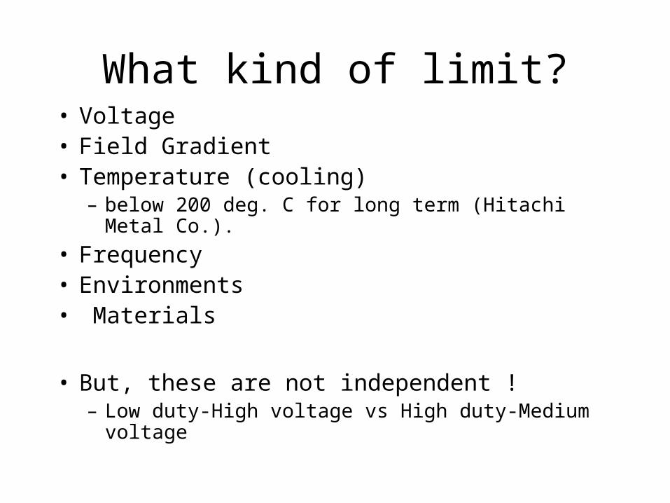
What kind of limit?• Voltage• Field Gradient• Temperature (cooling)
– below 200 deg. C for long term (Hitachi Metal Co.).
• Frequency• Environments• Materials
• But, these are not independent !– Low duty-High voltage vs High duty-Medium voltage
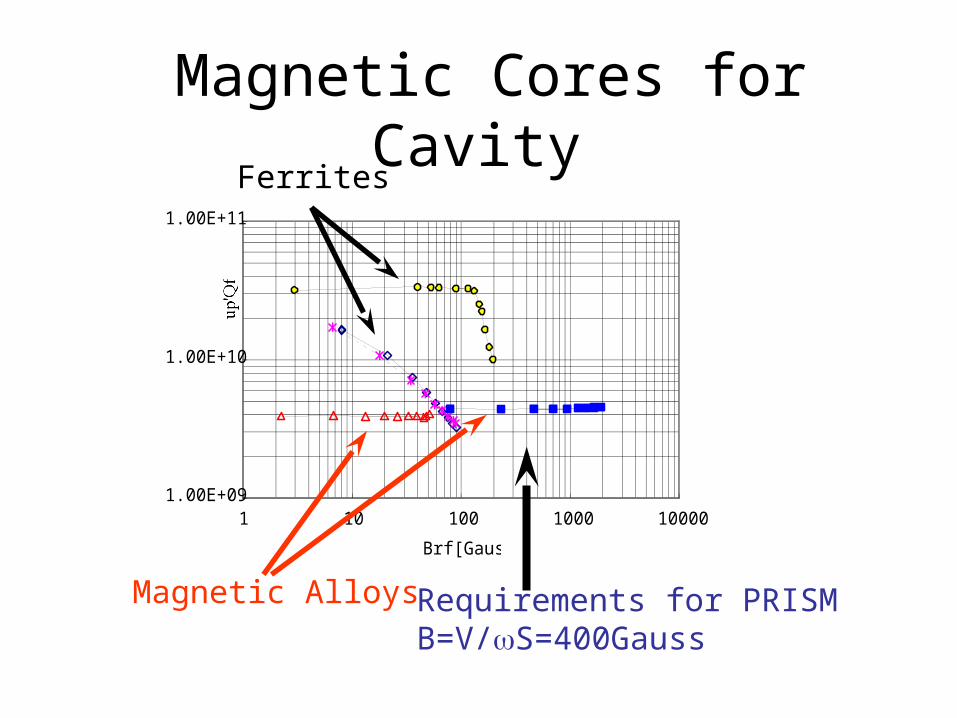
Magnetic Cores for Cavity
1.00E+09
1.00E+10
1.00E+11
1 10 100 1000 10000
Brf[Gauss]
up'Qf
Magnetic Alloys
Ferrites
Requirements for PRISMB=V/S=400Gauss
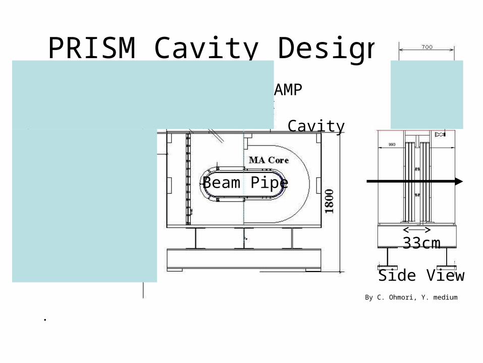
PRISM Cavity Design
.
APS
AMP
Cavity
By C. Ohmori, Y. medium
Beam Pipe
Side View
33cm
RF CavitiesField Gradient of Cavities for Proton
Synchrotrons Proton Synchrotron RF System
0
10
20
30
40
50
60
0 2 4 6 8 10 12
Frequency (MHz)
Field Gradient (kV/m)
SATUNE
MIMAS
CERN PSB
CERN PS
AGS
ISIS
KEK BSTR
KEK PS
JKJÅ@50GeV MR
JKJ Å@3GeV RCS
50GeV MR Upgrade
KEK-HGC
Ferrite Cavities
JKJ RF CavitiesKEK-PS MA Cavity
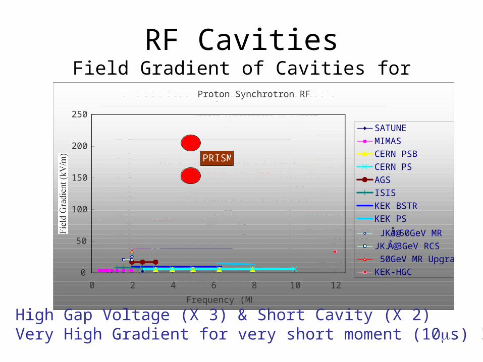
Proton Synchrotron RF System
0
50
100
150
200
250
0 2 4 6 8 10 12
Frequency (MHz)
Field Gradient (kV/m)
SATUNE
MIMAS
CERN PSB
CERN PS
AGS
ISIS
KEK BSTR
KEK PS
JKJÅ@50GeV MRJKJ Å@3GeV RCS 50GeV MR UpgradeKEK-HGC
PRISM
High Gap Voltage (X 3) & Short Cavity (X 2)Very High Gradient for very short moment (10s) !
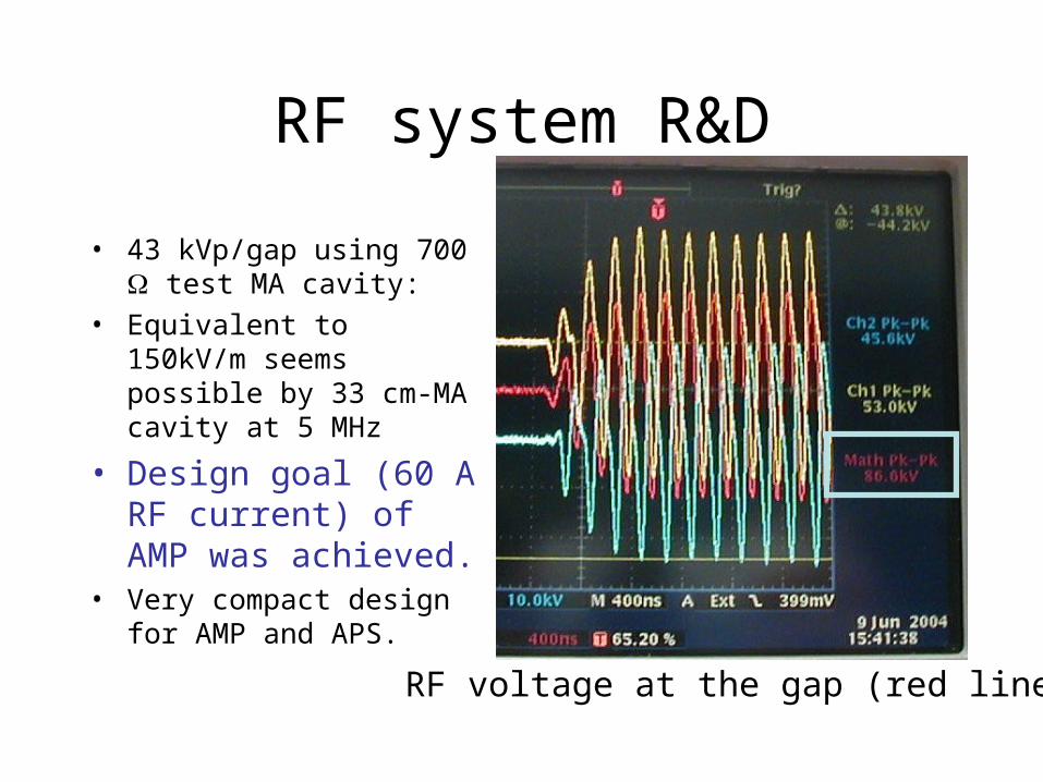
RF system R&D
• 43 kVp/gap using 700 test MA cavity:
• Equivalent to 150kV/m seems possible by 33 cm-MA cavity at 5 MHz
• Design goal (60 A RF current) of AMP was achieved.
• Very compact design for AMP and APS.
RF voltage at the gap (red line)
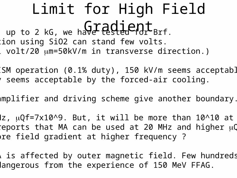
Limit for High Field GradientSo far, up to 2 kG, we have tested for Brf.Insulation using SiO2 can stand few volts.
(1 volt/20 m=50kV/m in transverse direction.)
For PRISM operation (0.1% duty), 150 kV/m seems acceptable.1%-duty seems acceptable by the forced-air cooling.
Power amplifier and driving scheme give another boundary.
At 5 MHz, Qf=7x10^9. But, it will be more than 10^10 at 10MHz.RIKEN reports that MA can be used at 20 MHz and higher Qf.
More field gradient at higher frequency ?
But, MA is affected by outer magnetic field. Few hundreds gauss seems dangerous from the experience of 150 MeV FFAG.
Limits for high duty operation• Cooling of MA cores is main issue.• But, reduction of impedance happens by
environmental conditions (capacitance and magnetic field)
• Cooling schemes– Air KEK-PSBooster
– Indirect water 150 MeV FFAG
– Direct Water cooling J-PARC, CERN-LEIR
Forced Air cooling• At KEK-PS booster, ferrite cavities have been
replaced by MA cavities.– 20 Hz, 40-500 MeV– 30-40 kV– Duty : 25-30%– Impedance ?– Power dissipation ?
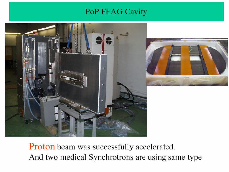
• Pop FFAG uses air cooling.
Indirect Cooling• J-PARC R&D shows 5 kW/core (80 cm OD) seems
acceptable without significant impedance reduction. – But, 5kW is not enough for J-PARC– Conflict between cooling efficiency and impedance.
• 150 MeV FFAG can be operated with 25-50 Hz repetition. Cavity impedance is reduced by the magnetic field.
• FNAL MA cavity• New HIMAC MA cavity (Toshiba core)• Saclay
• Possible to use at high frequency if you design carefully.
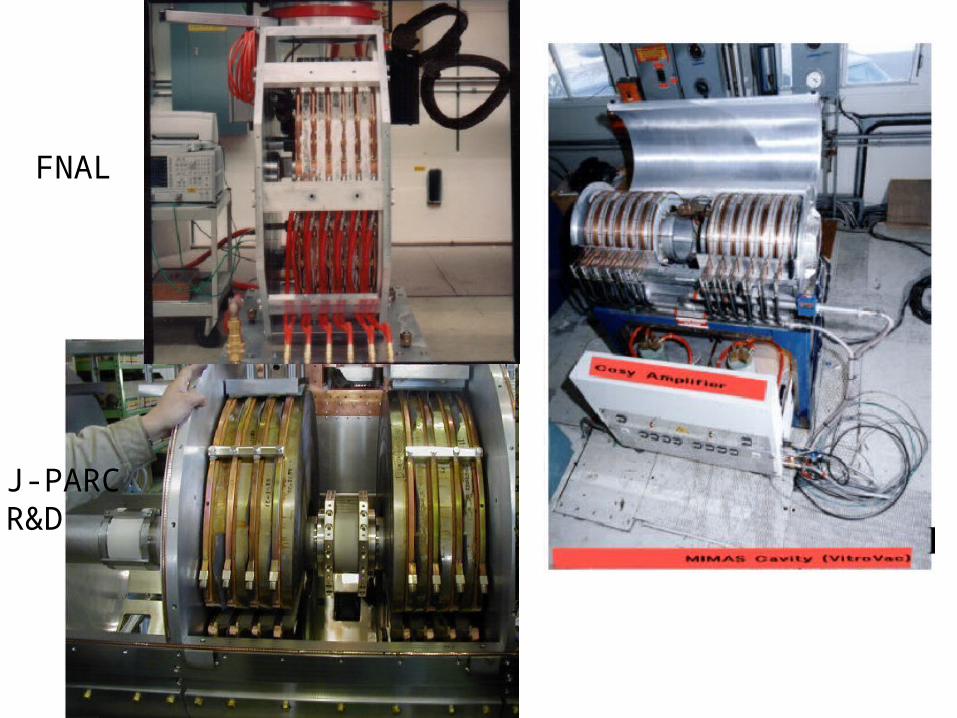
FNAL
J-PARCR&D
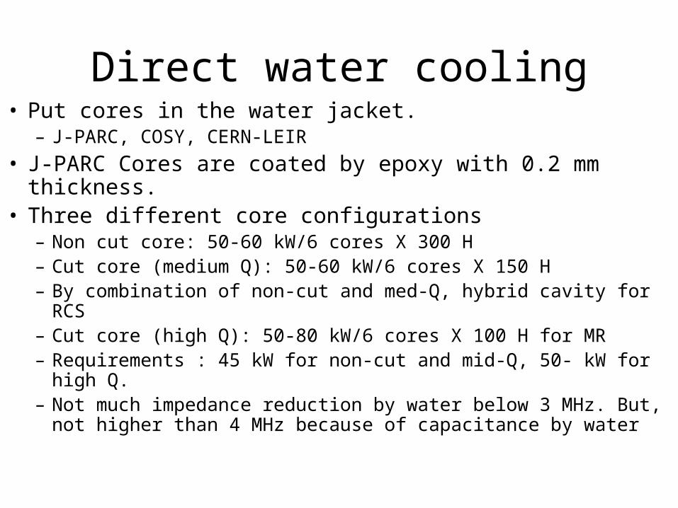
Direct water cooling• Put cores in the water jacket.
– J-PARC, COSY, CERN-LEIR
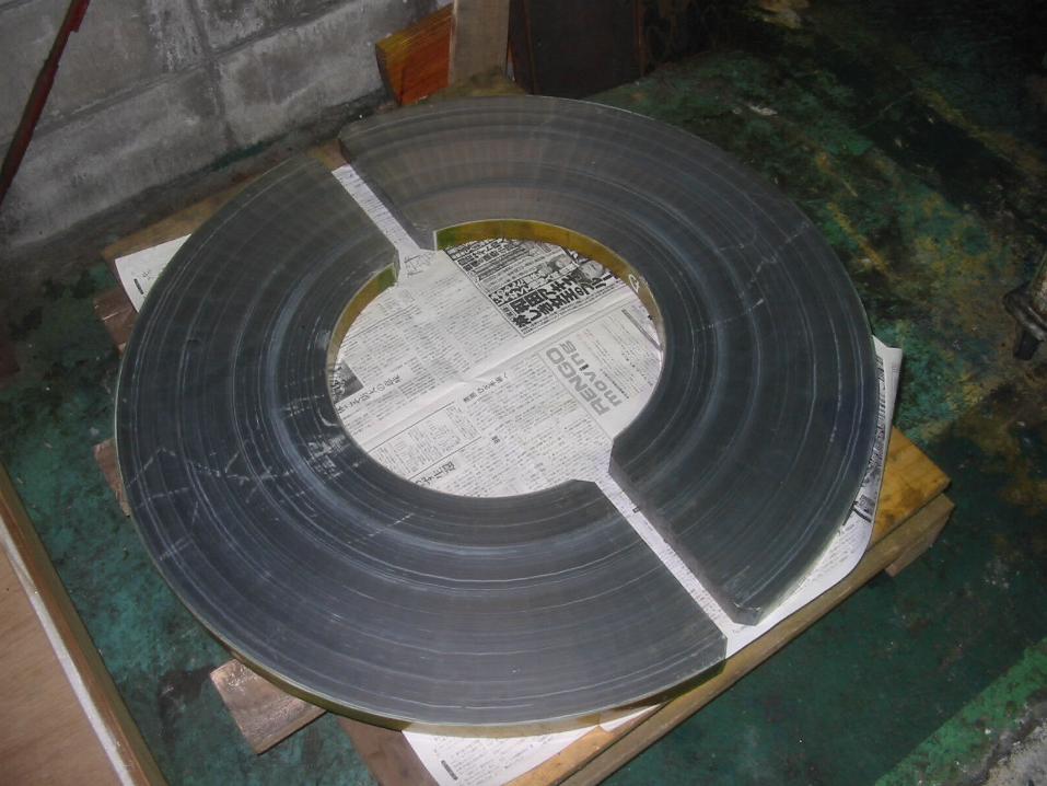
• J-PARC Cores are coated by epoxy with 0.2 mm thickness. • Three different core configurations
– Non cut core: 50-60 kW/6 cores X 300 H– Cut core (medium Q): 50-60 kW/6 cores X 150 H– By combination of non-cut and med-Q, hybrid cavity for RCS– Cut core (high Q): 50-80 kW/6 cores X 100 H for MR– Requirements : 45 kW for non-cut and mid-Q, 50- kW for high Q.– Not much impedance reduction by water below 3 MHz. But, not
higher than 4 MHz because of capacitance by water
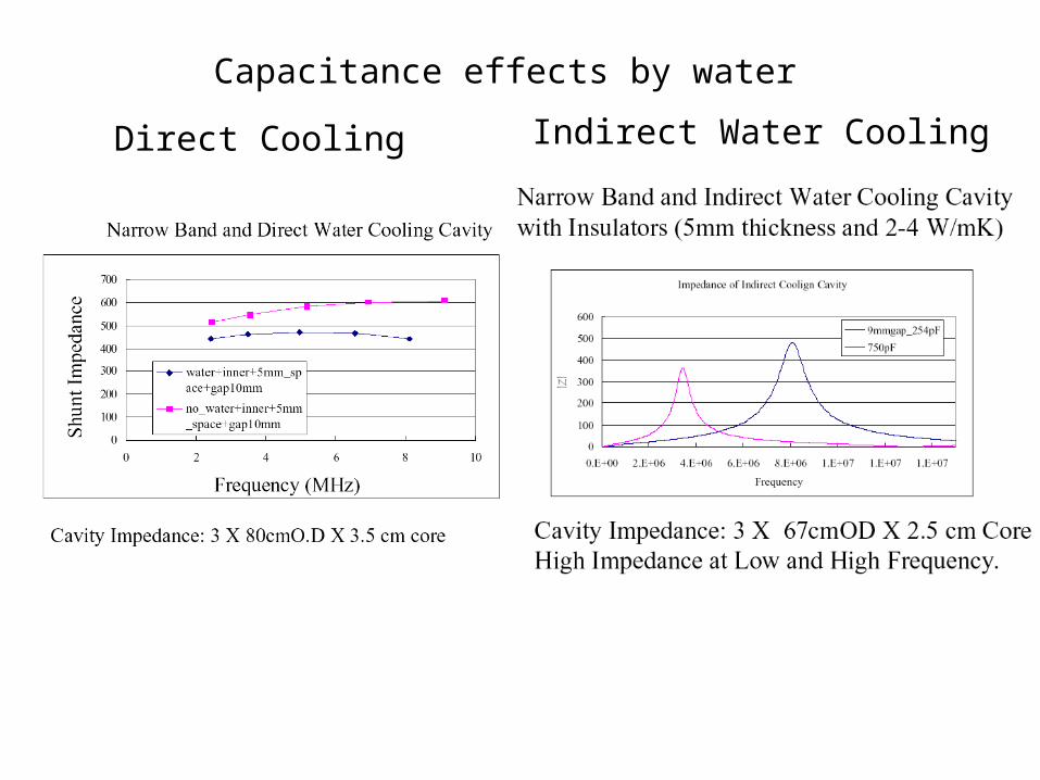
Capacitance effects by water
Direct Cooling Indirect Water Cooling
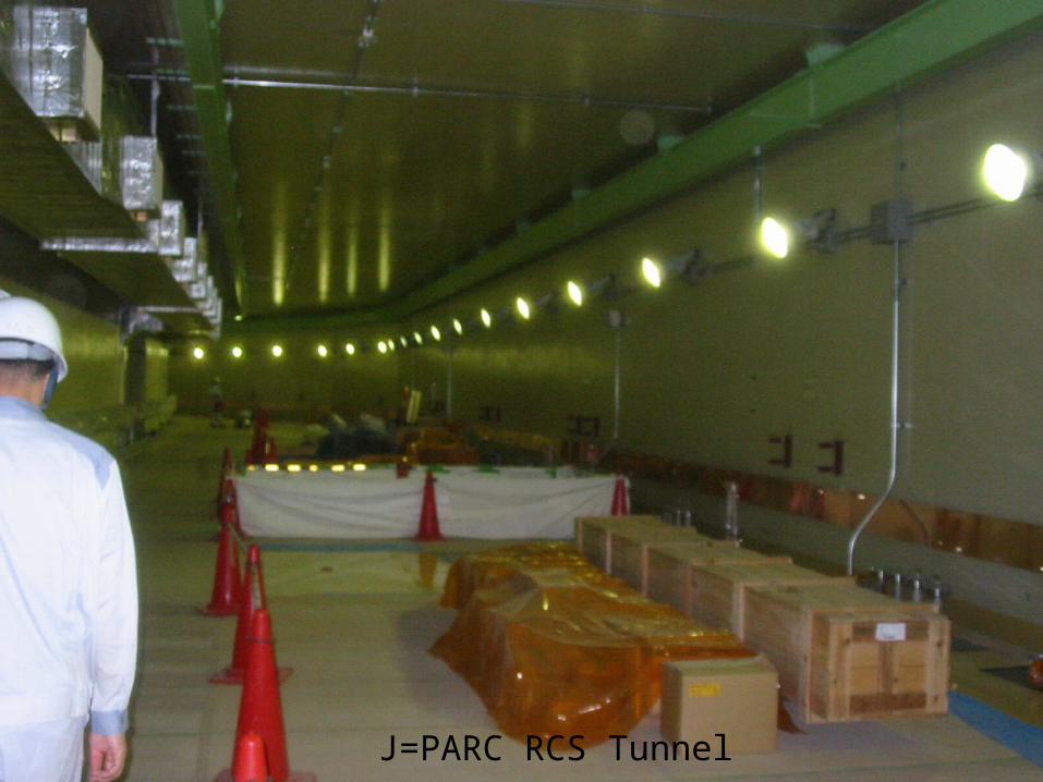
J=PARC RCS Tunnel

CERN-LEIR Cavity ( 2005/4 )


