50
INSTALLATION GUIDE LX100 Vehicle Accessory Interface Kit | 22.01.18 LIN VEHICLE ACCESSORY INTERFACE

INSTALLATION GUIDELX100 Vehicle Accessory Interface Kit | 22.01.18
LINVEHICLE ACCESSORY INTERFACE

PAGE 2
| LX100 VEHICLE ACCESSORY INTERFACE KIT INSTALLATION GUIDE
WHAT IS LINX?

| LX100 VEHICLE ACCESSORY INTERFACE KIT INSTALLATION GUIDE
PAGE 3
WHAT ISLINX?
INTRODUCING TOTAL CONTROL
LINX is a unique modern controller that declutters the dashboard and centralises the command of vehicle accessories by replacing classic switches, gauges and monitors with one sleek and smart driver interface. Built on an expandable platform, LINX will continue to evolve your on and off road driving experience both now and into the future.
The mobile touchscreen display integrates seamlessly into the vehicle cabin and mounts to a LINX Display Gimbal Mount that’s installed within easy reach of the driver. This connects to the LINX Controller which is the brains behind the system, and is conveniently installed out-of-sight either underneath the dash or the seat.
STAY IN THE LOOPFor the latest details, updates and list of accessories, head over to:
www.linx.arb.com.au
LINX is a sleek touchscreen interface that enables total control of both new and existing 4X4 Accessories. Gone are the days where the only option for installing aftermarket switches meant drilling multiple holes into the dashboard.
| LX100 VEHICLE ACCESSORY INTERFACE KIT INSTALLATION GUIDE
PAGE 4
TABLE OFCONTENTS
Get to know the basic in’s and out’s of your brand new LINX - the next generation of 4x4 Accessories.
KIT CONTENTS
WHAT’S IN THE BOX? .................................................................
SPECIFICATIONS
SPECIFICATIONS OVERVIEW .......................................................
LINX CONTROLLER LAYOUT .........................................................
TERMINALS FUNCTION TABLE ....................................................
CONTROLLER INSTALLATION
REQUIRED TOOLS ......................................................................
WIRING TECHNICAL NOTE ...........................................................
MOUNTING THE CONTROLLER .....................................................
CONNECTING POWER ................................................................
BLUETOOTH PAIRING DISPLAY WITH CONTROLLER ........................
CONNECTING TO VEHICLE AUTOMATION INPUTS ...........................
CONFIGURING NEGATIVELY SWITCHED INPUTS ..............................
INTEGRATION WITH COMPRESSOR WIRING HARNESS ....................
BATTERY VOLTAGE MONITOR CONNECTION ..................................
SWITCHBOARD CONNECTION .....................................................
CONNECTING THE USB CABLE ....................................................
INSTALLING THE DISPLAY MOUNT ................................................
INSTALLING OPTIONAL LINX ACCESSORIES
LINX PRESSURE PRESSURE CONTROL KIT ....................................
AIR SUSPENSION ISOLATION KIT .................................................
A-PILLAR BRACKETS .................................................................
01.
p. 9
p. 11
p. 13
p. 15
p. 15
p. 17
p. 18
p. 19
p. 20
p. 21
p. 22
p. 22
p. 23
p. 24
p. 25
p. 27
p. 30
p. 33
02.
03.
04.
05.
06.
07.
08.
09.
10.
11.
p. 7

| LX100 VEHICLE ACCESSORY INTERFACE KIT INSTALLATION GUIDE
PAGE 5
A-PILLAR BRACKET KIT 1 ............................................................
A-PILLAR BRACKET KIT 2 ............................................................
A-PILLAR BRACKET KIT 3 ............................................................
A-PILLAR BRACKET KIT 4 ............................................................
A-PILLAR BRACKET KIT 5 ............................................................
COMPLIANCE INFORMATION
EUROPE - EU DECLARATION OF CONFORMITY ...............................
USA - FCC STATEMENT ..............................................................
ENVIRONMENTAL PROTECTION ...................................................
p. 34
p. 36
p. 38
p. 38
p. 42
p. 47
p. 48
p. 48

PAGE 6
| LX100 VEHICLE ACCESSORY INTERFACE KIT INSTALLATION GUIDE
KIT CONTENTS
BACK TO TABLE OF CONTENTS

| LX100 VEHICLE ACCESSORY INTERFACE KIT INSTALLATION GUIDE
PAGE 7
Get to know your starter LINX kit components, their pur-pose and part numbers.
01.WHAT’S IN THE BOX?
LINX Controller PRODUCT CODE: 7450102
LINX DisplayPRODUCT CODE: 7450102
LINX Gimbal Display MountPRODUCT CODE: 7450103
DIN Rail 180mmPRODUCT CODE: 7450210
Wiring Harness - LINX Inputs PRODUCT CODE: 180426
Wiring Harness- LINX Patch PRODUCT CODE: 180420
Wiring Harness- LINX PowerPRODUCT CODE: 180423
USB Cable PRODUCT CODE: 7450104
LINX Terminal KitPRODUCT CODE: 7450105

PAGE 8
| LX100 VEHICLE ACCESSORY INTERFACE KIT INSTALLATION GUIDE
SPECIFICATIONS
BACK TO TABLE OF CONTENTS

| LX100 VEHICLE ACCESSORY INTERFACE KIT INSTALLATION GUIDE
PAGE 9
02.SPECIFICATIONSOVERVIEW
CONTROLLER FEATURES
Operates from 12VDC (nominal) power
25 digital outputs for switching low wattage devices such as relays and solenoids
8 digital inputs for detecting the state of switches
2 analog inputs for measuring battery voltages
7 analog inputs for sensor inputs
Bluetooth based communication link for communication with LINX Display
USB port for communication with LINX Display, and charging the battery in the LINX Display
Clip-off connection cover for securing wiring connections and promoting tidy wiring
Quick rail mounting system allows the LINX Controller wiring connections to be made in an open area before mounting, then quickly and securely mounted in confined space.
FCC, CE and RCM certification
Dimensions: 180mm x 126mm x 44mm Weight: 0.38KG
DISPLAY FEATURES
ARB LINX App
ARB LINX magnetic mounting system
Android operating system
USB, Bluetooth, and Wifi connectivity
GPS
Capacitive touch screen
FCC, CE and RCM certification Weight: 0.16KG
CONTROLLER MINIMUM RATINGS
DESCRIPTION MIN NOMINAL MAX UNITS
Power supply voltage 9.0 12.8 16.0 VDC
Power supply current 8.0 A
Digital output current 0.5 A
Digital input voltage 16.0 VDC
Battery voltage inputs 16.0 VDC
Analog sensor inputs 5.0 VDC
USB charging port voltage 5.1 VDC
USB charging port current 1.4 A
NOTE: Please refer to Operation Guide for further information on setup and use of each module.

| LX100 VEHICLE ACCESSORY INTERFACE KIT INSTALLATION GUIDE
PAGE 10
The LINX Controller terminals are grouped into blocks for referencing purposes and to simplify identification. The groups do not relate to individual LINX Modules, such as Traction or Switchboard.
The relationship between LINX functions and LINX Controller terminals is specified in the LINX Terminals Function Table.
The groups are labelled from A to O, and the terminals in each group are numbered from left to right as shown in the following figures.
03.LINX CONTROLLER LAYOUT
The bottom row of connection terminals (see above) are groups A, B, C, D, E, F and G and contain the group of power terminals, digital outputs and digital inputs.
A B C D E F G
Power Digital Output Digital Output Digital Output Digital Output Digital Output Digital Input
1 2 3 1 2 3 4 5 1 2 3 4 5 1 2 3 4 5 1 2 3 4 5 1 2 3 4 5 1 2 3 4 5 6 7 8

| LX100 VEHICLE ACCESSORY INTERFACE KIT INSTALLATION GUIDE
PAGE 11
The terminals will be referenced when connecting wiring harnesses in accordance with the following examples:
Connect the power positive wire (red) to terminal A1, and the ground negative wire (black) to terminal A2.:
Connect the accessory wire to digital output terminal C3:
H I J K L M N O USB
Batteries 2 & 3 Sensor Sensor Sensor Sensor Sensor Sensor Sensor USB Port
1 2 1 2 3 1 2 3 1 2 3 1 2 3 1 2 3 1 2 3 1 2 3 1
The top row of connection terminals are groups: H, I, J, K, L, M, N, O and USB. These groups contain all the connections related to the analog sensor inputs and the USB port.
EXAMPLE ONE EXAMPLE TWO

| LX100 VEHICLE ACCESSORY INTERFACE KIT INSTALLATION GUIDE
PAGE 12
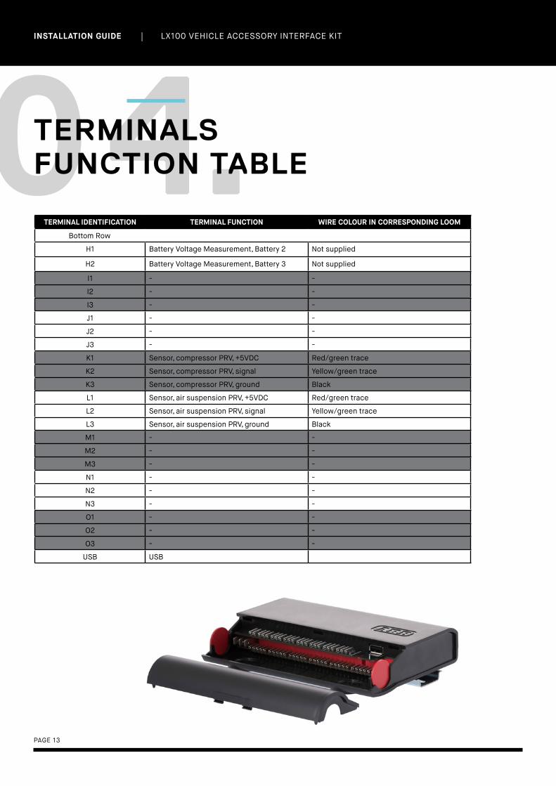
04.TERMINALS FUNCTION TABLE
TERMINAL IDENTIFICATION TERMINAL FUNCTION WIRE COLOUR IN CORRESPONDING LOOM
Bottom Row
A1 Power, battery positive (+12VDC), also Bat-tery Voltage Measurement Battery 1
Red
A2 Power, battery negative (vehicle ground) Black
A3 - -
B1 - -
B2 Air Locker solenoid, front Dark green/white trace
B3 - -
B4 Air Locker solenoid, rear Yellow/white trace
B5 Compressor, compressor wiring harness relay
Red/white trace
C1 Compressor, PRV, inflate solenoid Orange
C2 Compressor, PRV, deflate solenoid Purple
C3 Switchboard, Accessory 1 relay Not supplied
C4 Switchboard, Accessory 2 relay Not supplied
C5 Switchboard, Accessory 3 relay Not supplied
D1 Switchboard, Accessory 4 relay Not supplied
D2 Switchboard, Accessory 5 relay Not supplied
D3 Switchboard, Accessory 6 relay Not supplied
D4 Air Suspension, PRV, inflate solenoid Orange
D5 Air Suspension, PRV, deflate solenoid Purple
E1 Air Suspension, front left isolation solenoid Orange
E2 Air Suspension, front right isolation solenoid Purple
E3 Air Suspension, rear left isolation solenoid Orange
E4 Air Suspension, rear right isolation solenoid Purple
E5 - -
F1 - -
F2 - -
F3 - -
F4 - -
F5 - -
G1 Input, vehicle ACC power (+12VDC) Grey/red trace
G2 Input, parker lights/low beam Grey/yellow trace
G3 Input, headlight high beam Grey/blue trace
G4 Input, reverse light Grey/purple trace
G5 Input, switch, Air Locker, front Green
G6 Input, switch, Air Locker, rear Yellow
G7 - -
G8 - -
| LX100 VEHICLE ACCESSORY INTERFACE KIT INSTALLATION GUIDE
PAGE 13
TERMINAL IDENTIFICATION TERMINAL FUNCTION WIRE COLOUR IN CORRESPONDING LOOM
Bottom Row
H1 Battery Voltage Measurement, Battery 2 Not supplied
H2 Battery Voltage Measurement, Battery 3 Not supplied
I1 - -
I2 - -
I3 - -
J1 - -
J2 - -
J3 - -
K1 Sensor, compressor PRV, +5VDC Red/green trace
K2 Sensor, compressor PRV, signal Yellow/green trace
K3 Sensor, compressor PRV, ground Black
L1 Sensor, air suspension PRV, +5VDC Red/green trace
L2 Sensor, air suspension PRV, signal Yellow/green trace
L3 Sensor, air suspension PRV, ground Black
M1 - -
M2 - -
M3 - -
N1 - -
N2 - -
N3 - -
O1 - -
O2 - -
O3 - -
USB USB
04.TERMINALSFUNCTION TABLE

PAGE 14
| LX100 VEHICLE ACCESSORY INTERFACE KIT INSTALLATION GUIDE
CONTROLLERINSTALLATION
BACK TO TABLE OF CONTENTS
| LX100 VEHICLE ACCESSORY INTERFACE KIT INSTALLATION GUIDE
PAGE 15
The following tools may be required for the installation of the LINX Controller:
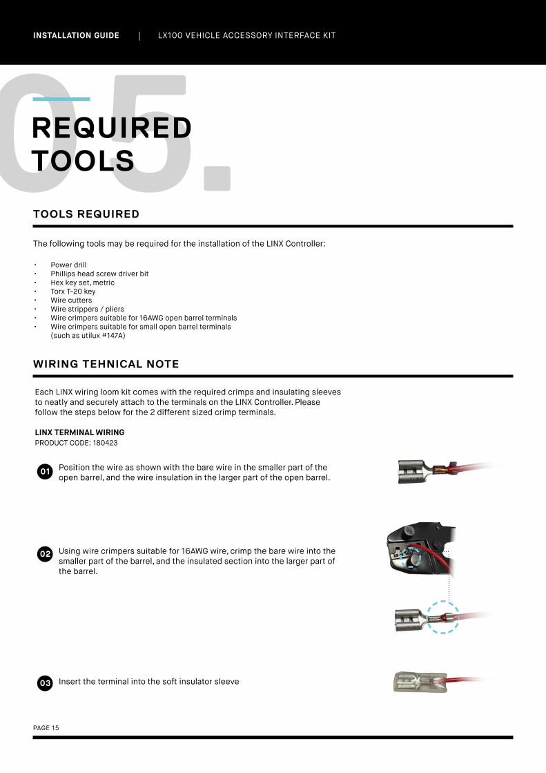
05.REQUIRED TOOLS
TOOLS REQUIRED
• Power drill• Phillips head screw driver bit• Hex key set, metric• Torx T-20 key• Wire cutters• Wire strippers / pliers• Wire crimpers suitable for 16AWG open barrel terminals• Wire crimpers suitable for small open barrel terminals
(such as utilux #147A)
Each LINX wiring loom kit comes with the required crimps and insulating sleeves to neatly and securely attach to the terminals on the LINX Controller. Please follow the steps below for the 2 different sized crimp terminals.
LINX TERMINAL WIRINGPRODUCT CODE: 180423
WIRING TEHNICAL NOTE
• Position the wire as shown with the bare wire in the smaller part of the open barrel, and the wire insulation in the larger part of the open barrel.
• Using wire crimpers suitable for 16AWG wire, crimp the bare wire into the smaller part of the barrel, and the insulated section into the larger part of the barrel.
• Insert the terminal into the soft insulator sleeve
01
02
03
| LX100 VEHICLE ACCESSORY INTERFACE KIT INSTALLATION GUIDE
PAGE 16
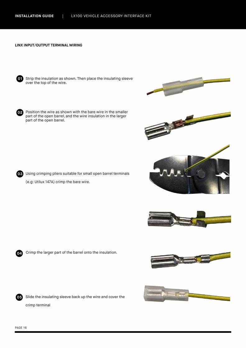
LINX INPUT/OUTPUT TERMINAL WIRING
01
02
03
04
05
Strip the insulation as shown. Then place the insulating sleeve over the top of the wire.
Position the wire as shown with the bare wire in the smaller part of the open barrel, and the wire insulation in the larger part of the open barrel.
Using crimping pliers suitable for small open barrel terminals
(e.g: Utilux 147A) crimp the bare wire.
Crimp the larger part of the barrel onto the insulation.
Slide the insulating sleeve back up the wire and cover the
crimp terminal
| LX100 VEHICLE ACCESSORY INTERFACE KIT INSTALLATION GUIDE
PAGE 17
06.MOUNTING THE CONTROLLER
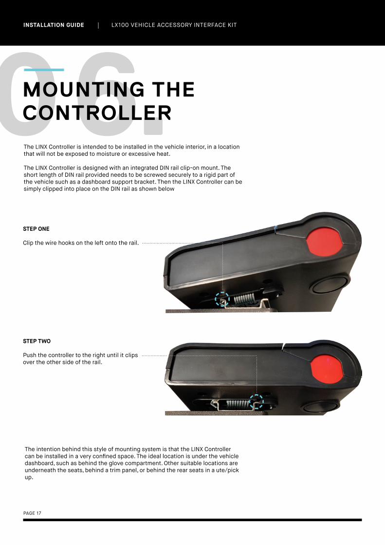
The LINX Controller is intended to be installed in the vehicle interior, in a location that will not be exposed to moisture or excessive heat.
The LINX Controller is designed with an integrated DIN rail clip-on mount. The short length of DIN rail provided needs to be screwed securely to a rigid part of the vehicle such as a dashboard support bracket. Then the LINX Controller can be simply clipped into place on the DIN rail as shown below
STEP ONE
Clip the wire hooks on the left onto the rail.
STEP TWO
Push the controller to the right until it clips over the other side of the rail.
The intention behind this style of mounting system is that the LINX Controller can be installed in a very confined space. The ideal location is under the vehicle dashboard, such as behind the glove compartment. Other suitable locations are underneath the seats, behind a trim panel, or behind the rear seats in a ute/pick up.

| LX100 VEHICLE ACCESSORY INTERFACE KIT INSTALLATION GUIDE
PAGE 18
The LINX Controller should be connected to the vehicle main battery. Using a multimeter check for approximately 12.7V (engine not running) to confirm the battery is in good condition.
Using the provided wiring harness, part number 180423, run the wiring from the battery end which already has the terminals and fuse holder assembled, to the LINX Controller end which is unterminated. This way the unterminated end can pass through rubber grommets and small holes, and be extended or shortened at the LINX Controller end if required.
07.CONNECTING POWER
Position the ring terminal with black heat shrink near the negative battery terminal, and position the ring terminal with red heat shrink near the positive battery terminal. Neatly run the wiring harness from the battery to the LINX Controller, making sure it can be secured with cable ties at 200mm intervals, grouped together with a vehicle factory wiring harness if possible and avoiding hot or moving parts that could damage the harness.
Determine if the wiring harness needs to be extended or can be shortened, ensuring that it can be connected to the battery and LINX Controller at both ends without tension on the wire to prevent fatigue and damage to the terminals.
If the wiring harness needs to be extended, ensure the additional wire used is an equivalent or larger wire gauge than the existing 1.25mm2 (16AWG) wire.
Crimp the terminals onto the wire as described above in the wiring tech note. Connect the power positive wire (red) to terminal A1, and the ground negative wire (black) to terminal A2.
NOTE:
At this stage it is a good idea to check if the LINX Controller is powered on before doing any further wiring. To complete this, you will need to turn on the LINX Display and then Bluetooth pair the LINX Display and LINX Controller (please see next page).

| LX100 VEHICLE ACCESSORY INTERFACE KIT INSTALLATION GUIDE
PAGE 19
BLUETOOTH PAIRING THE DISPLAY WITH CONTROLLER
Access the BLUETOOTH SETTINGS by:
2. Tap SETTINGS and select BLUETOOTH
1. Open up the APP DRAWER
2. Once paired, the LINX Display screen should change to the main split screen view, and be
displaying the vehicle’s battery voltage
1. Tap ‘ARB LINX’ from the available devices.
To pair with LINX:
NOTE:Once the Display and Controller have been Bluetooth paired, the LINX Controller will become invisible to all other devices.

| LX100 VEHICLE ACCESSORY INTERFACE KIT INSTALLATION GUIDE
PAGE 20
Using the 180426 (LINX Inputs Wiring Harness) provides the LINX with pickups from the following vehicle circuits: ACC power, parker light/low beam illumination, high beam illumination, reverse.
Always connect all inputs for maximum LINX automation functionality.
ACC PICKUPThe ACC power pickup can be taken from the ARB compressor wiring harness (red/yellow) which also requires ACC power. If an ARB compressor isn’t installed then ACC power pickup location will be different for every vehicle, but a good starting point is cigarette lighter/12V sockets, or other factory dashboard switches for things such as fog lights.
PARKER LIGHT/LOW BEAM PICKUPThe parker light/low beam pickup can again be taken from the ARB compressor wiring harness (blue/white) which has illumination for the dashboard switches. If an ARB compressor isn’t installed then this will be different for every vehicle, but a good starting point is from other factory dashboard switches that also have illumination.
HIGH BEAM PICKUPThe high beam pickup can be taken from the back of the headlight, as it is with the various ARB driving light looms. If driving light loom is already installed then the same high beam pickup can be used.
Note with negatively switched headlights, the pickup should come from the negative switched side of the light globe. The input pickup will need to be configured as described in the following section.
REVERSE PICKUPThe reverse pickup location will be different for every vehicle but is usually found easiest at the vehicle tail lights.
CONNECTING TO VEHICLE AUTOMATION INPUTS
DESCRIPTION WIRE COLOUR CONTROLLER TERMINAL CODE
ACC power pickup Grey / Red stripe G1
Parker / Low Beam pickup
Grey / Yellow stripe G2
High Beam pickup Grey / Blue strpe G3
Reverse Light pickup Grey / Purple stripe G4
CONNECTION TABLE
| LX100 VEHICLE ACCESSORY INTERFACE KIT INSTALLATION GUIDE
PAGE 21
CONFIGURING NEGATIVELY SWITCHED INPUTS
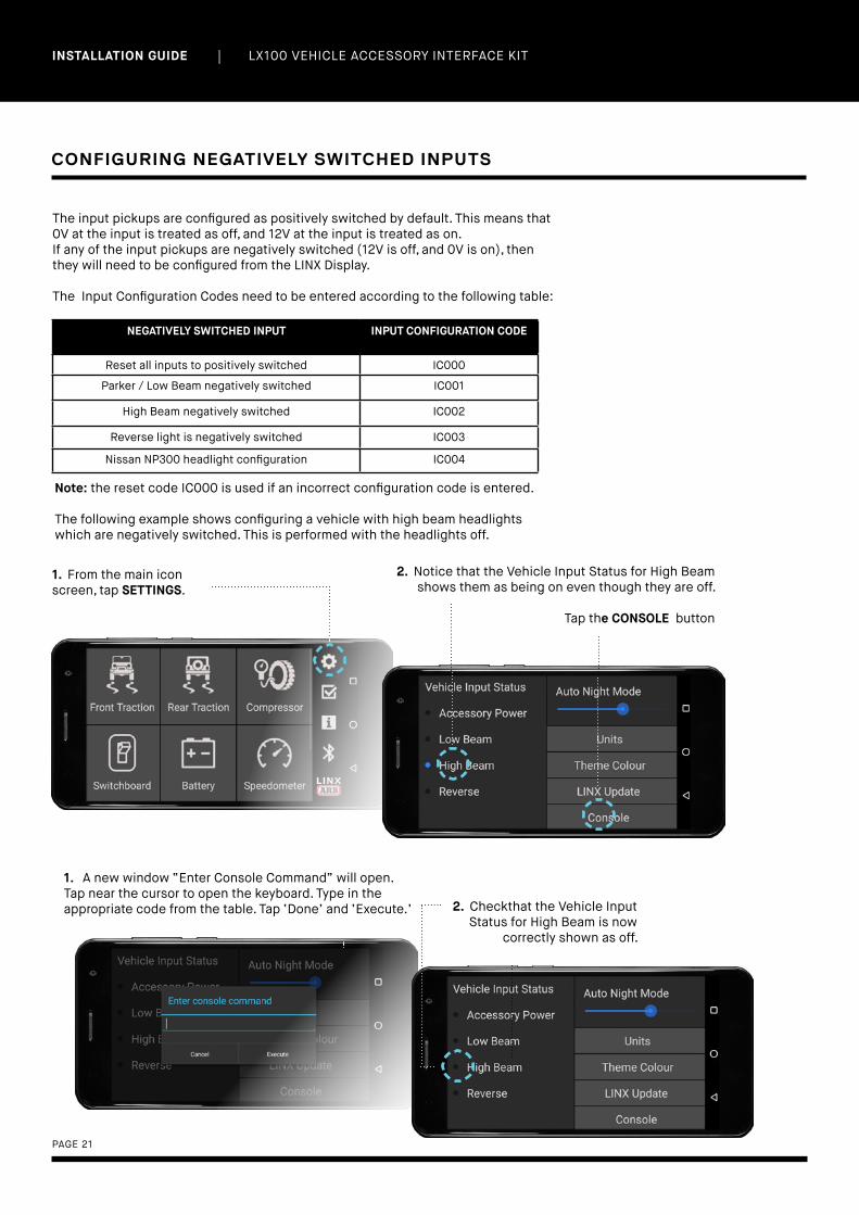
The input pickups are configured as positively switched by default. This means that 0V at the input is treated as off, and 12V at the input is treated as on. If any of the input pickups are negatively switched (12V is off, and 0V is on), then they will need to be configured from the LINX Display.
The Input Configuration Codes need to be entered according to the following table:
NEGATIVELY SWITCHED INPUT INPUT CONFIGURATION CODE
Reset all inputs to positively switched IC000
Parker / Low Beam negatively switched IC001
High Beam negatively switched IC002
Reverse light is negatively switched IC003
Nissan NP300 headlight configuration IC004
1. From the main icon screen, tap SETTINGS.
Note: the reset code IC000 is used if an incorrect configuration code is entered.
The following example shows configuring a vehicle with high beam headlights which are negatively switched. This is performed with the headlights off.
2. Notice that the Vehicle Input Status for High Beam shows them as being on even though they are off.
Tap the CONSOLE button
1. A new window “Enter Console Command” will open. Tap near the cursor to open the keyboard. Type in the appropriate code from the table. Tap ‘Done’ and ‘Execute.’ 2. Checkthat the Vehicle Input
Status for High Beam is now correctly shown as off.
| LX100 VEHICLE ACCESSORY INTERFACE KIT INSTALLATION GUIDE
PAGE 22
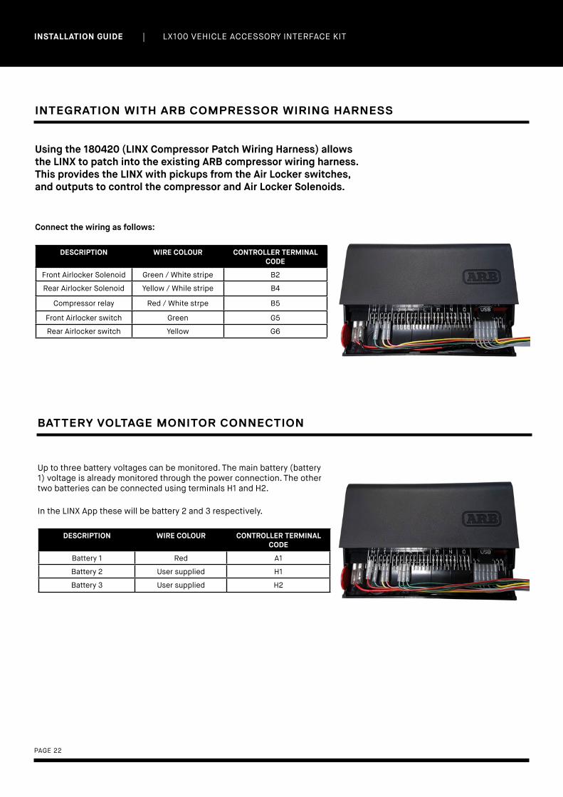
INTEGRATION WITH ARB COMPRESSOR WIRING HARNESS
Using the 180420 (LINX Compressor Patch Wiring Harness) allows the LINX to patch into the existing ARB compressor wiring harness. This provides the LINX with pickups from the Air Locker switches, and outputs to control the compressor and Air Locker Solenoids.
Connect the wiring as follows:
BATTERY VOLTAGE MONITOR CONNECTION
Up to three battery voltages can be monitored. The main battery (battery 1) voltage is already monitored through the power connection. The other two batteries can be connected using terminals H1 and H2.
In the LINX App these will be battery 2 and 3 respectively.
DESCRIPTION WIRE COLOUR CONTROLLER TERMINAL CODE
Front Airlocker Solenoid Green / White stripe B2
Rear Airlocker Solenoid Yellow / While stripe B4
Compressor relay Red / White strpe B5
Front Airlocker switch Green G5
Rear Airlocker switch Yellow G6
DESCRIPTION WIRE COLOUR CONTROLLER TERMINAL CODE
Battery 1 Red A1
Battery 2 User supplied H1
Battery 3 User supplied H2

| LX100 VEHICLE ACCESSORY INTERFACE KIT INSTALLATION GUIDE
PAGE 23
The ARB LINX switchboard module has been designed to replace all of your aftermarket accessory switches.
CONNECTION TO ARB DRIVING LIGHT LOOM
For connection to ARB driving light loom the following steps must be taken
SWITCHBOARD CONNECTION
1. Unplug the bullet connectors on the black/white wire and black earth wire, and remove the switch and fuse from the loom.
2. Connect the black/white wire from the relay to the required switchboard output (C3, C4, C5, D1, D2, D3) as per the wiring tech note. HINT: Wiring terminals and insulator sleeves are available in 7450105 (ARB LINX Terminal Kit).
3. The black earth wire that used to run from the relay to the switch is no longer required and can be removed from the loom.
NOTE: Do not remove the short earth wire with eye terminal, as this is needed to earth the relay.
CONNECTION TO OTHER ACCESSORIES
For connection to other accessories ARB recommends the use of 180422 (LINX Relay Harness).
Simply connect the green/white wire to the required switchboard output (C3, C4, C5, D1, D2, D3) as per the wiring tech note, and join the rest of the accessory wiring to the appropriate flying leads in the relay block.
NOTE: Pins C3, C4 & C5 have been connected to 180422 (LINX Relay Harness) in the above image.

| LX100 VEHICLE ACCESSORY INTERFACE KIT INSTALLATION GUIDE
PAGE 24
CONNECTING THE USB CABLE
The USB connection can be used to power and charge the LINX Display, and provide the communications channel between the LINX Controller and LINX Display.
The provided USB Cable (7450104), has a USB A connector at one end for connection to the LINX Controller, and a USB micro B (back angled) connector at the other end for connection to the LINX Display.
The USB cable should be secured to the LINX Controller using a cable tie as shown below. This prevents vibration or cable strain from damaging the USB connection.
NOTE:
The LINX Display can also be connected to an alternate USB power socket. In this case, the communications channel will be via Bluetooth only.
• USB cable• Alternative USB power socket.
USB CABLE

| LX100 VEHICLE ACCESSORY INTERFACE KIT INSTALLATION GUIDE
PAGE 25
08.INSTALLINGDISPLAY MOUNT
CENTRE BOLT
THUMB NUT
The LINX Display Gimbal Mount can be fixed to a vehicle specific A-pillar bracket (which is available separately) or directly screwed to a dashboard if desired.
LINX DISPLAY GIMBAL MOUNT
STEP ONE
Unscrew the thumb nut and remove the centre bolt.
STEP TWO
Hold the steel bracket in one hand, and the pivot assembly in the other hand. Then pull them apart.
STEP THREE
Remove the mount screw cover from the steel bracket.
STEP FIVE
Reassemble by following the steps in reverse.
MOUNT SCREWCOVER
Firstly, the mount must be disassembled as shown below:
STEP FOUR
Screw or bolt the steel bracket to the dashboard, console, or LINX A-Pillar bracket.

PAGE 26
| LX100 VEHICLE ACCESSORY INTERFACE KIT INSTALLATION GUIDE
INSTALLING OPTIONALLINX ACCESSORIES
BACK TO TABLE OF CONTENTS

| LX100 VEHICLE ACCESSORY INTERFACE KIT INSTALLATION GUIDE
PAGE 27
09.LINX PRESSURECONTROL KIT
The LINX Pressure Control Kit (7540107) provides the capability to control the air pressure in any connected item. It is required hardware for accessory inflation/deflation (Compressor Module – Pressure Control Option) and it is also used for controlling air suspension pressures (Air Suspension Module).
LINX Pressure Control Kit contains a LINX PRV (Pressure Regulating Valve), a LINX Pressure Transducer, and 2 associated wiring looms.
WIRING HARNESS, LINX TRANSDUCER
WIRING HARNESS, LINX SOLENOID PAIRPRODUCT CODE: 180421
PRODUCT CODE: 180425
PRESSURE TRANSDUCERPRODUCT CODE: 180902
PRV (PRESSURE REGULATING VALVE)PRODUCT CODE: 180105

| LX100 VEHICLE ACCESSORY INTERFACE KIT INSTALLATION GUIDE
PAGE 28
GENERAL INSTALLATION PROCEDURE
1. Connect an inlet port of the LINX PRV to a compressed air supply (e.g., an output port of an ARB Air Compressor).
2. Install the LINX pressure transducer into an output port of the LINX PRV.
3. Connect an output port of the LINX PRV to your air filler hose, air accessory, or isolation valves.
4. Connect the solenoid harness.
5. Connect the transducer harness.
6. Connect the body ground.
7. Route and connect both harnesses to the LINX controller.
OUTPUT
INPUT/SUPPLYAlternate or daisy chain function to screw extra solenoid valve into.
INPUT/SUPPLY
EXHAUST
OUTPUT OUTPUT
1. The LINX PRV must be connected to a compressed air source that has a higher minimum output pressure than the maximum required of any connected accessory. The LINX PRV comes with a 1/8 BSPT nipple pre-installed. If desired this can be relocated to the input port on the opposite side by removing the threaded plug.
Notes: Always use thread sealant or PTFE tape to seal all tapered threaded joints. O-ring sealed parallel threaded joints do not require sealant or tape. All ARB Air Compressors come with threaded ports configured to connect to the threaded nipple.
2. The LINX pressure transducer can be screwed into any of the three available LINX PRV output ports (labelled above) by removing and discarding the threaded plug. Choose the output that best suits your particular installation.
Notes: The LINX Pressure Transducer does not require thread sealant. Do not over tighten.
3. Connect any of the remaining two output ports of the LINX PRV to the
LINX PRV PORT IDENTIFICATION

| LX100 VEHICLE ACCESSORY INTERFACE KIT INSTALLATION GUIDE
PAGE 29
DESCRIPTION WIRE COLOUR CONTROLLER TERMINAL CODE
Sensor power Red / Green stripe K1
Sensor signal Yellow / Green stripe K2
Sensor ground Black K3
Solenoid pair, inflate Orange C1
Solenoid pair, deflate Purple C2
CONNECTION TABLE
air lines or accessories to be controlled by the pressure control kit.
4. Attach the two connectors of the LINX Solenoid Pair wiring harness (180425) to the two solenoid coils of the LINX PRV. Note that the connector with the purple wire should be matched only with the deflate valve coil (shown on the right directly opposite to the exhaust fitting). Retain the connectors using the supplied screws.
5. Connect the transducer
connector of the LINX Transduce wiring harness (180421) to the transducer by inserting it until it clicks in.
6. Connect the ring terminal (black wire) to a body ground (e.g., bolt or screw into body steel).
7. Route both wiring harnesses to the controller making sure not to leave the wires under tension after they are secured. Trim off excess length or lengthen harnesses if necessary. Terminate (see Wiring Termination tech note) and connect both harnesses to the LINX controller using the following table:
| LX100 VEHICLE ACCESSORY INTERFACE KIT INSTALLATION GUIDE
PAGE 30
The LINX Air Suspension Isolation Kit (7450109) is installed as an upgrade to an existing LINX Pressure Control Kit (7450107), and it provides the capability to isolate accessories for the purpose of varying the pressure between them.
A good example of this is in using separate air bag/air spring pressures to load level a vehicle front to back and/or side to side.
Note: The following hardware requirements for Air Suspension configuration:
10.LINX AIR SUSPENSIONISOLATION KIT
CONFIGURATION LINX HARDWARE REQUIREMENT
One airline joined between any number of air bags/springs equally where all air bags/springs share the same pressure and a linked path between them.
1 x 7450107 (isolation kit not req’d)
One airline split to control 2 air bag/spring pressures independently with no pathway between them
1 x 74501071 x 7450109
One airline split to control 3 or 4 air bag/spring pressures independently with no pathway between them
1 x 74501072 x 7450109
Installing this module requires that the LINX Pressure Control Kit (7450107) is pre-connected to the air supply (refer to installation section).

| LX100 VEHICLE ACCESSORY INTERFACE KIT INSTALLATION GUIDE
PAGE 31
WIRING HARNESS, LINX SOLENOID PAIRPRODUCT CODE: 180425
2 x SOLENOID, 12V 2/2, DAISY CHAINABLEPRODUCT CODE: 180106
The threaded nipple of the first solenoid should be screwed into the most suitable PRV output port (i.e., one of the free output ports of the LINX Pressure Control Kit). Or alternatively they can be remote mounted by connecting an airline between a PRV output port and one of the 2 input ports (labelled #1) of the solenoids.
The second solenoid is attached to the first by removing the threaded plug from an input port of the first and screwing the threaded nipple of the second into the port.
Notes:
• Always use thread sealant or PTFE tape to seal all tapered threaded joints.
• O-ring sealed parallel threaded joints do not require sealant or tape.
• All ARB Air Compressors come with threaded ports
configured to connect to the threaded nipple (1/8 BSPT/BSPP).
• Isolation kits for Air Suspension control cannot be
connected to a LINX. Pressure Control Kit that is being used for compressor pressure control (e.g., tyre inflation). Air Suspension control requires its own LINX Pressure Control Kit.

| LX100 VEHICLE ACCESSORY INTERFACE KIT INSTALLATION GUIDE
PAGE 32
The figures below demonstrate how configurable the LINX PRV and LINX Air Suspension Kit are due to the daisy chainability and multiple outlet ports.
Many more arrangements are possible so experiment with the possibilities to find the arrangement that best suits your installation.
LONG NARROW CONFIGURATION
SHORT CONFIGURATION
CONFIGURATIONS

| LX100 VEHICLE ACCESSORY INTERFACE KIT INSTALLATION GUIDE
PAGE 33
Designed to suit a large range of popular 4WD’s the LINX A-Pillar Brackets provide a secure location for the LINX Display Screen that is in easy reach of the driver, while avoiding having to make additional holes in the vehicle dashboard.
Utilising the LINX Display Gimbal Mount, the display can be orientated and set in the desired position.
PART # DESCRIPTION MAKE MODEL YEAR
7450106 Linx A-Pillar Bracket Kit 1 ToyotaToyotaToyotaToyotaToyotaToyotaMitsubishi
HiluxHilux 2015 onPrado 120Prado 150Fortuner79 series 5 star ANCAPTriton
2005-20152015-onAllAll2015 on2016 on2016 on
7450110 Linx A-Pillar Bracket Kit 2 Toyota 200 series Land Cruiser All
7450111 Linx A-Pillar Bracket Kit 3 FordFordMazdaNissanNissanVolkswagen
RangerEverestBT-50Patrol Y62Patrol GUAmarok
All
7450112 Linx A-Pillar Bracket Kit 4 Jeep JK Wrangler All
7450113 Linx A-Pillar Bracket Kit 5 Toyota 79 Series single cab (pre ANCAP)79 Series dual cab
All
11.A-PILLARBRACKETS

| LX100 VEHICLE ACCESSORY INTERFACE KIT INSTALLATION GUIDE
PAGE 34
A-PILLAR BACKET KIT 1 (745106)
INSTALLATION STEPS
STEP ONE:
Expose the A-pillar pinch weld seam by pulling the door seal away in the area shown.
STEP TWO:
Position the A-pillar Bracket in a suitable location along the A-pillar pinch weld seam. Mark the position with tape.
Note: Consider positioning it as low as practical to avoid any chance of blocking the drivers view of the road, avoiding SRS airbags, but still making sure that the LINX Mount and Display doesn’t contact the vehicle dashboard or door trim when the door is closed.
STEP THREE:
Hold the A-pillar Bracket on the outer side of the pinch weld seam to mark the position of the holes to drill.

| LX100 VEHICLE ACCESSORY INTERFACE KIT INSTALLATION GUIDE
PAGE 35
STEP FOUR:
Drill the holes with a 4.5mm drill bit. Take care not to scratch the A-pillar paintwork with the drill chuck, or drill through into anything that might be located in the A-pillar such as wiring, SRS air bags, plastics, etc.
STEP FIVE:
Loosely assemble the Linx Mount onto the Linx A-pillar Bracket using the M6 bolts and nuts provided in the kit and hand tighten.
STEP SIX:
Then re-position the A-pillar Bracket in between the pinch weld seam and the interior plastic trim panel, then insert the M4 Torx head screws in from the outside and tighten using a T-20 Torx key or driver bit.
At this step you can also tighten up the M6 nuts securing the Linx Mount to the A-pillar Bracket and reassemble it.
STEP SEVEN:
Partially reinstall the door seal and mark the section that interferes with the A-pillar Bracket.

| LX100 VEHICLE ACCESSORY INTERFACE KIT INSTALLATION GUIDE
PAGE 36
STEP EIGHT:
Then using tin snips cut a section from the middle web of the door seal.
STEP NINE:
Complete the installation by reinstalling the door seal.
A-PILLAR BACKET KIT 2 (7450110)
The installation of all the A-pillar Bracket Kits are similar, but the Toyota 200 series Landcruiser installation has a few addition steps.
STEP ONE:
Unbolt and remove the grab handle from the A-pillar.
STEP TWO:
Remove the A-pillar trim panel.
| LX100 VEHICLE ACCESSORY INTERFACE KIT INSTALLATION GUIDE
PAGE 37
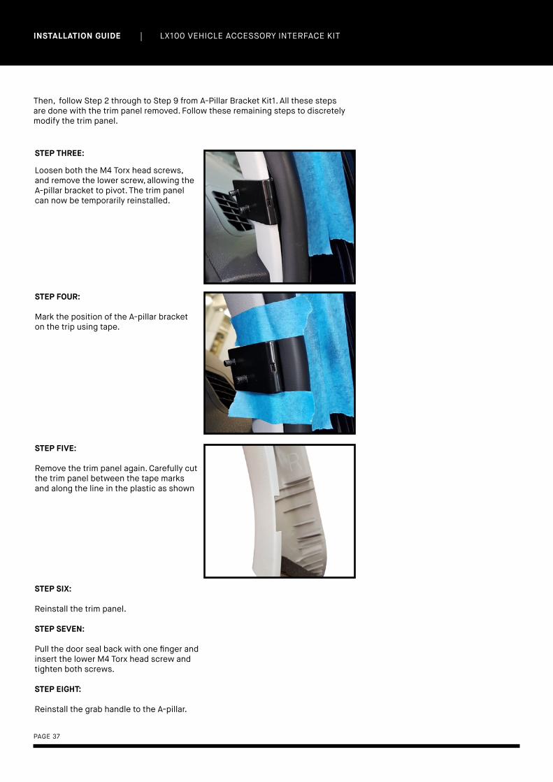
STEP THREE:
Loosen both the M4 Torx head screws, and remove the lower screw, allowing the A-pillar bracket to pivot. The trim panel can now be temporarily reinstalled.
STEP FOUR:
Mark the position of the A-pillar bracket on the trip using tape.
STEP FIVE:
Remove the trim panel again. Carefully cut the trim panel between the tape marks and along the line in the plastic as shown
Then, follow Step 2 through to Step 9 from A-Pillar Bracket Kit1. All these steps are done with the trim panel removed. Follow these remaining steps to discretely modify the trim panel.
STEP SIX:
Reinstall the trim panel.
STEP SEVEN:
Pull the door seal back with one finger and insert the lower M4 Torx head screw and tighten both screws.
STEP EIGHT:
Reinstall the grab handle to the A-pillar.

| LX100 VEHICLE ACCESSORY INTERFACE KIT INSTALLATION GUIDE
PAGE 38
A-PILLAR BACKET KIT 3 (7450111)
For the installation of this bracket follow the same procedure as A-Pillar Bracket Kit 1.
A-PILLAR BACKET KIT 4 (7450112)
INSTALLATION STEPS
STEP ONE:
Remove the A-pillar upper trim panel by unscrewing the fastener shown, and the sun visor.
UPPER TRIM PANEL

| LX100 VEHICLE ACCESSORY INTERFACE KIT INSTALLATION GUIDE
PAGE 39
STEP TWO:
Remove the lower A-pillar trim panel by pulling it away from the windscreen.
STEP THREE:
Position the A-pillar Bracket as shown. It should be against a flat surface, below the rib/lump in the pinch weld seam as shown.
Note: it shouldn’t be so low as to interfere with the retaining clip on the back of the trim panel.
STEP FOUR:
Hold the A-pillar Bracket on the outer side of the pinch weld seam to mark the position of the holes to drill.
STEP FIVE:
Drill the holes with a 4.5mm drill bit. Take care not to scratch the A-pillar paintwork with the drill chuck, or drill through into anything that might be located in the A-pillar such as wiring, SRS air bags, plastics, etc.
LOWER TRIM PANEL

| LX100 VEHICLE ACCESSORY INTERFACE KIT INSTALLATION GUIDE
PAGE 40
STEP SIX:
Then re-position the A-pillar Bracket on the inner side of the pinch weld seam and insert the M4 Torx head screws in from the outside and lightly and temporarily tighten using a T-20 Torx key.
STEP SEVEN:
Measure and record the position of each hole from the A-pillar seam weld, and height above the dash.
STEP EIGHT:
Reinstall the A-pillar trim panel and measure the overhang as shown.
Note: The bracket might interfere with the clip on the back of the trim panel while trying to reinstall it. So to facilitate this remove the lower Torx head screw, allowing the bracket to rotate out of the way.

| LX100 VEHICLE ACCESSORY INTERFACE KIT INSTALLATION GUIDE
PAGE 41
STEP NINE:
Using the recorded measurements mark the hole positions on the A-pillar trim panel. Remember to add the overhang measurement to the horizontal measurements.
For example: From the previous photos the first hole position will be 24mm + 5mm = 29mm from the edge of the trim panel, and 48mm above the dashboard.
STEP TEN:
Drill a small pilot hole through the trim panel and check that your positions are correctly centred over the holes in the Linx A-pillar Bracket.
STEP ELEVEN:
Open up the holes to 14mm to clear the 12mm spacer washers provided in the kit (7450410). Then reinstall the A-pillar trim panel, and insert the lower Torx head screw and tighten both of them.
STEP TWELVE:
Assemble the Linx Gimbal Mount Bracket with the M6 bolts and space washers as shown.
Note: RHD installation shown. For LHD installation shift the bolts across 1 slot.

| LX100 VEHICLE ACCESSORY INTERFACE KIT INSTALLATION GUIDE
PAGE 42
STEP THIRTEEN:
Assemble the Linx Gimbal Mount Bracket with the M6 bolts and space washers as shown.
STEP FOURTEEN:
Reassemble the Linx Display Gimbal Mount with the long through bolt inserted from the door side and the thumb nut on the central side. This is ensure there is clearance between the Mount the door when closed.
Note : RHD installation shown. For a LHD installation reverse the installation of the throught bolt and thumb nut.
A-PILLAR BACKET KIT 5 (7450113)

| LX100 VEHICLE ACCESSORY INTERFACE KIT INSTALLATION GUIDE
PAGE 43
INSTALLATION STEPS
STEP ONE: Expose the A-pillar pinch weld seam by pulling the pinch weld PVC trim away in the area shown.
STEP TWO: Hold the A-pillar Bracket to the Linx Display Gimbal Mount as shown. Note the orientation of the flange relative to the gimbal mount.
STEP THREE: Position the A-pillar Bracket in a suitable location along the A-pillar pinch weld seam. Mark the position with tape
Note: Consider positioning it as low as practical to avoid any chance of blocking the drivers view of the road, avoiding SRS airbags, but still making sure that the Linx Mount and Display doesn’t contact the vehicle dashboard or. door trim when the door is closed
STEP FOUR: Turn the A-pillar Bracket upside down, then hold it on the outer side of the pinch weld seam to mark the position of the holes to drill.

| LX100 VEHICLE ACCESSORY INTERFACE KIT INSTALLATION GUIDE
PAGE 44
STEP FIVE:
Drill the holes with a 4.5mm drill bit. Take care not to scratch the A-pillar paintwork with the drill chuck, or drill through into anything that might be located in the A-pillar such as wiring, SRS air bags, plastics, etc.
STEP SIX:
The Linx A-pillar Bracket must be fixed up against the pinch weld seam, without the plastic trim panel sandwiched in between. Carefully cut the trim panel between the tape marks as shown. Note: This cut line will be concealed by the pinch weld PVC trim.
STEP SEVEN:
Loosely assemble the Linx Mount onto the Linx A-pillar Bracket using the M6 bolts and nuts provided in the kit and hand tighten.
STEP EIGHT:
Then re-position the A-pillar Bracket on the inside of the pinch weld seam, then insert the M4 Torx head screws in from the outside and tighten using a T-20 Torx key or driver bit.
At this step you can also tighten up the M6 nuts securing the Linx Mount to the A-pillar Bracket and reassemble it.

| LX100 VEHICLE ACCESSORY INTERFACE KIT INSTALLATION GUIDE
PAGE 45
STEP NINE: Complete the installation by reinstalling the pinch weld PVC trim.
Note: to allow the pinch weld PVC trim to sit and flat over the screws, cut away the internal fingers in this area

PAGE 46
COMPLIANCEINFORMATION
BACK TO TABLE OF CONTENTS

| LX100 VEHICLE ACCESSORY INTERFACE KIT INSTALLATION GUIDE
PAGE 47
13.COMPLIANCE INFORMATION
EUROPE - EU DECLARATION OF CONFORMITY
This declaration of conformity is issued under the sole responsibility of the manufacturer.
This declaration relates to these products:LINX 1.0
The products are in conformity with the following standards or standardized documents:
ETSI EN 301 489-17 V2.2.1:2012ETSI EN 301 489-1 V1.9.2:2011ETSI EN 300 328 V1.9.1:2015EN 60950-1:2006 + A11:2009 + A1:2010 + A12:2011 + A2:2013IEC 60950-1:2005 (Second Edition) + Am 1:2009 + Am 2:2013
According to the provisions of the directives:
1999/5/EC (Radio Equipment and Telecommunication Terminal Equipment Directive)2014/30/EU (Electromagnetic Compatibility Directive)2014/35/EU (Low Voltage Directive)
Technical file at:ARB Corporation Ltd, 42-44 Garden St, Kilsyth, Victoria, Australia
Signed for and on behalf of ARB Corporation Ltd
Andrew BrownManaging DirectorMelbourne, November 2017

| LX100 VEHICLE ACCESSORY INTERFACE KIT INSTALLATION GUIDE
PAGE 48
USA - FCC STATEMENT
This device complies with part 15 of the FCC Rules. Operation is subject to the following two conditions: (1) this device may not cause harmful interference, and (2) this device must accept any interference received, including interference that may cause undesired operation.
This equipment has been tested and found to comply with the limits for a Class B digital device, pursuant to part 15 of the FCC Rules. These limits are designed to provide reasonable protection against harmful interference in a residential installation. This equipment generates, uses and can radiate radio frequency energy and, if not installed and used in accordance with the instructions, may cause harmful interference to radio communications. However, there is no guarantee that interference will not occur in a particular installation. If this equipment does cause harmful interference to radio or television reception, which can be determined by turning the equipment off and on, the user is encouraged to try to correct the interference by one or more of the following measures:
• Reorient or relocate the receiving antenna.• Increase the separation between the equipment
and receiver.• Connect the equipment into an outlet on a
circuit different from that to which the receiver is connected.
• Consult the dealer or an experienced radio/TV technician for help.
FCC CAUTIONSChanges or modifications made to this device that are not expressly approved by ARB Corporation Ltd may void the user’s authority to operate the equipment.This device must not be co-located or operated in conjunction with any other antenna or transmitter.
FCC RADIATION EXPOSURE STATEMENTThis equipment complies with FCC radiation exposure limits set forth for an uncontrolled environment. This equipment should be installed and operated with minimum distance of 20 cm between the radiator and your body.
ENVIRONMENTAL PROTECTION
Waste electrical products should not be disposed of with household waste. Please recycle where facilities exist. Check with your local authority or retailer for recycling advice.

SETUP COMPLETE?Find out how you can unleash the full
power of your brand new LINX device...
VIEW OPERATIONS MANUAL
T H E N E X T G E N E R A T I O N O F4 X 4 A C C E S S O R I E S

ARB STORES
VICTORIA
Bairnsdale (03) 5152 1226
Ballarat (03) 5336 4605
Bendigo (03) 5445 7100
Brighton (03) 9557 1888
Dandenong (03) 9793 0002
Echuca (03) 5480 2600
Geelong (03) 5272 2611
Hoppers Crossing (03) 9749 5905
Keilor Park (03) 9331 7333
Kilsyth (03) 9761 6622
Pakenham (03) 5940 5500
Shepparton (03) 5822 1877
Somerton (03) 9460 9988
Traralgon (03) 5174 9190
SOUTH AUSTRALIA
Elizabeth (08) 8252 1599
Morphett Vale (08) 8186 6101
Regency Park (08) 8244 5001
ACT
Fyshwick (02) 6280 7475
NEW SOUTH WALES
Albury (02) 6021 2477
Artarmon (02) 9438 4484
Broken Hill (08) 8087 9250
Brookvale (02) 8507 3073
Dubbo (02) 6885 5777
Moorebank (02) 9821 3633
Newcastle (02) 4953 9555
Orange (02) 6369 0700
Penrith (02) 4731 1266
Port Macquarie (02) 6581 2500
St Peters (02) 9565 2455
Tamworth (02) 6762 0541
Thornleigh (02) 9980 8855
Wagga Wagga (02) 6925 8777
Wentworthville (02) 9631 7889
WESTERN AUSTRALIA
Canning Vale (02) 9455 4366
Geraldton (08) 9921 8077
Mandurah (08) 9583 3200
Osborne Park (08) 9244 3553
Wangara (08) 9409 5764
Welshpool (08) 9358 3688
NORTHERN TERRITORY
Alice Springs (08) 8953 0572
Darwin (08) 8947 2262
QUEENSLAND
Biggera Waters (07) 5537 8800
Bundaberg (07) 4153 2929
Burleigh Heads (07) 5535 9223
Caboolture (07) 5499 1955
Capalaba (07) 3823 5900
Cairns (07) 4035 3350
Caloundra (07) 5491 4500
Coopers Plains (07) 3277 2020
Jindalee (07) 3715 6400
Nundah (07) 3266 3255
North Lakes (07) 3491 9600
Springwood (07) 3493 3030
Mackay (07) 4998 6888
Maroochydore (07) 5475 4011
Rockhampton (07) 4922 7788
Toowoomba (07) 4632 1122
Townsville (07) 4728 0900
TASMANIA
Burnie (03) 6431 4494
Hobart (03) 6232 2333
Launceston (03) 6331 4190
INTERNATIONAL OFFICES
HEAD OFFICE
ARB 4X4 ACCESSORIES
42-44 Garden Street,
Kilsyth Victoria 3137 Australia
Tel: +61 (03) 9761 6622
Fax: +61 (03) 9761 6807
Email: [email protected]
Web: www.arb.com.au
NORTH AMERICA
720 SW 34th Street
Renton, WA 98057
Tel: +1 (425) 264 1391
Fax: +1 (425) 264 1392
Email: [email protected]
Web: www.arbusa.com
CENTRAL & SOUTH AMERICA
3700 Port Jacksonville Pkwy Suite
#1, Jacksonville FL 32226, USA
Tel: +1 (904) 379 8216
Fax: +1 (904) 813 7197
Email: [email protected]
THAILAND
Building GW1, 300/56,
Moo 1, Tambon Tasit,
Amphur Pluakdaeng,
Rayong, 21140, Thailand
Tel: +66 (0) 38 929 672
Fax: +66 (0) 38 929 676
Email: [email protected]
Web: www.arb.co.th
EUROPE
Na Dlouhém čc.80, DC2,
Ricany - Jažlovic,
251 01, Czech Republic
Tel: +420 323 040 900
Fax: +420 323 040 910
Email: [email protected]
Web: www.arbeurope.com
MIDDLE EAST
ARB Middle East FZE
LIU15, RA07AB05
Jebel Ali Freezone,
North Dubai, United Arab Emirates
Tel: +971 4 880 7005
Email: [email protected]
OTHER REGIONS
Please contact our
Export Department
Tel: +61 3 9761 6622
Email: [email protected]


