Lindab 1 General information and theory 2 Safe 3 Silencers 4 Dampers & Measure units 5 Fire dampers & Smoke evacuation 6 Air valves 7 Roof hoods 8 Other circular products 9 Transfer 10 Rectangular 11 Flexible ducting 12 Isol 13 Access doors 14 Smart tools 15 Duct suspensions & Support systems 16 Fastening material 17 Index 18 Air valves lindab | air valves
Transcript
Lindab 1
General information and theory 2
Safe 3
Silencers 4
Dampers & Measure units 5
Fire dampers & Smoke evacuation 6
Air valves 7
Roof hoods 8
Other circular products 9
Transfer 10
Rectangular 11
Flexible ducting 12
Isol 13
Access doors 14
Smart tools 15
Duct suspensions & Support systems 16
Fastening material 17
Index 18
Air valves
l indab | air valves
388 We reserve the right to make changes without prior notice
We reserve the right to make changes without prior notice 389
1
2
3
4
5
6
7
8
9
10
11
12
13
14
15
16
17
18
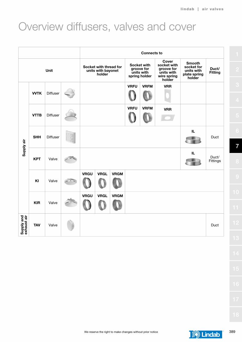
Overview diffusers, valves and cover
l indab | air valves
Connects to
UnitSocket with thread for
units with bayonet holder
Socket with groove for units with
spring holder
Cover socket with groove for units with
wire spring holder
Smooth socket for units with
plate spring holder
Duct/Fitting
Sup
ply
air
VVTK Diffuser
VRFU VRFM VRR
VTTB Diffuser
VRFU VRFM VRR
SHH Diffuser
IL
Duct
KPT Valve
ILDuct/
Fittings
KI Valve
VRGU VRGL VRGM
KIR Valve
VRGU VRGL VRGM
Sup
ply
and
exha
ust
air
TAV Valve Duct
390 We reserve the right to make changes without prior notice
1
2
3
4
5
6
7
8
9
10
11
12
13
14
15
16
17
18
l indab | air valves
Exh
aust
air
KVB Valve
VRFU VRFM VRR
KDPF Valve
VRGU VRGL VRGM VRFU VRFM VRR
KVGØ 100–
160Valve
VRFU VRFM VRR
KVGØ 200 Valve
VRGU VRGL VRGM
KU Valve
VRGU VRGL VRGM
KSU Valve
VRGU VRGL VRGM
KSUBValve
and fire damper
VRGU VRGL VRGM
KPF Valve
ILDuct/
Fittings
No
air
TLO Cover
VRFU VRFM VRR
Connects to
UnitSocket with thread for
units with bayonet holder
Socket with groove for units with
spring holder
Cover socket with groove for units with
wire spring holder
Smooth socket for units with
plate spring holder
Duct/Fitting
We reserve the right to make changes without prior notice 391
1
2
3
4
5
6
7
8
9
10
11
12
13
14
15
16
17
18
Diffuser supply air VVTK
l indab | air valves
DescriptionDiffuser for supply air.Designed for wall mounting. Spring holders connect to socket VRFU, VRFM or VRR.
* For Ø125 the outer part of the brim of the socket is visible. If this is not acceptable the cover plate VVTKR can be used to hide the brim.
Materials and finishMaterialPainted galvanized sheet metal.
ColourWhite RAL 9010, gloss 70, equivalent to NCS S 0502 Y.
MaintenanceThe visible parts can be wiped with a damp cloth.
Dimensions
Ordering exampleVVTK 100
ProductDimension Ød
Ødnom
lmm
mkg
100 90 0,31
125 * 90 0,31
Ø 1
35–1
45
l
Ød
a
VVTK
392 We reserve the right to make changes without prior notice
1
2
3
4
5
6
7
8
9
10
11
12
13
14
15
16
17
18
Diffuser supply air VVTK
l indab | air valves
Technical dataAir flow, q [l/s] and [m3/h],total pressure drop, Δpt [Pa],throw length, l0,2 [m], andA-weighted sound power level, LWA [dB], for different settings, a [mm], are shown in the graph.
Note! The A-weighted sound power level, LWA, will increase by 3 dB when the valve is mounted in a bend.
Sound power level, LW [dB], in octave bandsis calculated as LWA + Kok.Kok is found in the table below.
Sound attenuation, ΔL, [dB]
Air jet diffusion patternMaximum vertical width, bv = 0,1 × l0,2 mMaximum horizontal width, bh = 0,6 × l0,2 m
Measurement of air flowData is available in a separate brochure.
We reserve the right to make changes without prior notice 393
1
2
3
4
5
6
7
8
9
10
11
12
13
14
15
16
17
18
Cover plate VVTKR
l indab | air valves
DescriptionPlate to cover the outer part of the brim of the socket.
Materials and finishMaterialPainted galvanized sheet metal.
ColourWhite RAL 9010, gloss 70, equivalent to NCS S 0502 Y.
MaintenanceThe visible parts can be wiped with a damp cloth.
Dimensions
Cover plate together with valve VVTK Ø125
Ordering exampleVVTKR 125
ProductDimension Ød
Ødnom
mkg
125 0,07Ø
92
Ød
6
Ø14
5
VVTKR
394 We reserve the right to make changes without prior notice
1
2
3
4
5
6
7
8
9
10
11
12
13
14
15
16
17
18
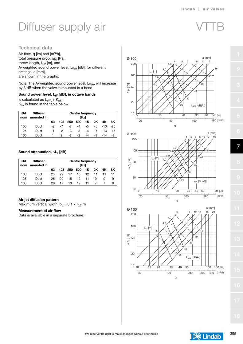
Diffuser supply air VTTB
l indab | air valves
DescriptionDiffuser for supply air.Designed with a prolonged neck for ceiling mounting. Is equipped with a fixed blanking-off segment for preventing the air flow in a desired direction.Spring holders connect to socket VRFU, VRFM or VRR.
Materials and finishMaterialPainted galvanized sheet metal.
ColourWhite RAL 9010, gloss 70, equivalent to NCS S 0502 Y.
MaintenanceThe visible parts can be wiped with a damp cloth.
Dimensions
Ordering exampleVTTB 125
ProductDimension Ød
Ødnom
ØDmm
lmm
mkg
100 155 70 0,44
125 185 76 0,60
160 226 83 0,85
Ød
ØD
l
a
VTTB
We reserve the right to make changes without prior notice 395
1
2
3
4
5
6
7
8
9
10
11
12
13
14
15
16
17
18
Diffuser supply air VTTB
l indab | air valves
Technical dataAir flow, q [l/s] and [m3/h],total pressure drop, Δpt [Pa],throw length, l0,2 [m], andA-weighted sound power level, LWA [dB], for different settings, a [mm], are shown in the graphs.
Note! The A-weighted sound power level, LWA, will increase by 3 dB when the valve is mounted in a bend.
Sound power level, LW [dB], in octave bandsis calculated as LWA + Kok.Kok is found in the table below.
Sound attenuation, ΔL, [dB]
Air jet diffusion patternMaximum vertical width, bv = 0,1 × l0,2 m
Measurement of air flowData is available in a separate brochure.
396 We reserve the right to make changes without prior notice
1
2
3
4
5
6
7
8
9
10
11
12
13
14
15
16
17
18
Diffuser SHH
l indab | air valves
DescriptionDiffuser for supply air.Designed for wall mounting.Fits in duct. Equipped with a single lip rubber gasket.
Materials and finishMaterialPainted sheet metal.
ColourWhite RAL 9010, gloss 30.
Dimensions
Ordering exampleSHH 100
ProductDimension Ød
Ødnom
mkg
100 0,60
125 0,60
156
Ød
21552
SHH
We reserve the right to make changes without prior notice 397
1
2
3
4
5
6
7
8
9
10
11
12
13
14
15
16
17
18
Diffuser SHH
l indab | air valves
Technical dataAir flow, q [l/s] and [m³/h],total pressure drop, Δpt [Pa],throw length, l0,2 [m], andA-weighted sound power level, LWA [dB], for differentsettings, n [number of open rows],are shown in the graph.
The setting is made by sealing off rows of holes with tape on the front's inside.
Sound power level, LW [dB], in octave bandsis calculated as LWA + Kok.Kok is found in the table below.
Sound attenuation, ΔL, [dB]
Measurement of air flowData is available in a separate brochure.
398 We reserve the right to make changes without prior notice
1
2
3
4
5
6
7
8
9
10
11
12
13
14
15
16
17
18
Valve KPT
l indab | air valves
DescriptionValve for supply air.Designed for ceiling mounting.Flat spring holders connect to duct.
Materials and finishMaterialPlastic.
ColourWhite RAL 9010.
Dimensions
Ordering exampleKPT 125
ProductDimension Ød
Ødnom
ØDmm
mkg
80 118 0,08
100 148 0,10
125 180 0,16
160 203 0,22
200 246 0,55
Ød
ØD
KPT
We reserve the right to make changes without prior notice 399
1
2
3
4
5
6
7
8
9
10
11
12
13
14
15
16
17
18
Valve KPT
l indab | air valves
Technical dataAir flow, q [l/s] and [m3/h],total pressure drop, Δpt [Pa], andA-weighted sound power level, LWA [dB], for differentsettings, n [number of opening turns],are shown in the graphs.
Sound power level, LWA [dB], A-weightedis shown in the graphs.
Sound attenuation, ΔLA, [dB]
Measurement of air flowData is available in a separate brochure.
Ødnom
Valve mounted in
Settingn
[number of opening turns]
AttenuationΔLA[dB]
100 Duct
023468
10
8,58,58,58888
125 Duct
0456789
1488
7,57
6,56
160 Duct
068
1012
14,56,5666
200 Duct
079
111315
15,56,56
5,55,55,5
Tolerance ±1
10
20
50
100
5 10 20 50 [l/s]
Δ p
t [P
a]
20
q
50 100 180 [m3/h]
Ø 100
200
30 40
2 3 4 68
LWA [dB]35
38
number of opening turns
10
20
50
100
5 10 20 80 [l/s]
Δ p
t [P
a]
20
q
50 100 200 [m3/h]
Ø 125
200
30 40 50
4 5 6 7 8 9
number of opening turns
10
20
50
100
10 15 20 130 [l/s]
Δ p
t [P
a]
40
q
100 200 300 [m3/h]
Ø 160
200
30 40 50
400
100
LWA [dB]
30
35
40
6 8 10 12
number of opening turns
400 We reserve the right to make changes without prior notice
1
2
3
4
5
6
7
8
9
10
11
12
13
14
15
16
17
18
Valve KPT
l indab | air valves
10
20
50
100
20 30 40 150 [l/s]
Δ p t
[Pa]
80
q
150 200 300 [m3/h]
Ø 200
200
50 100
400
200
100 500
LWA [dB]
30
35
40
7 9 11 13 15
number of opening turns
We reserve the right to make changes without prior notice 401
1
2
3
4
5
6
7
8
9
10
11
12
13
14
15
16
17
18
Valve KI
l indab | air valves
DescriptionValve for supply air.Designed for ceiling mounting.Bayonet holders connect to socket VRGU, VRGL or VRGM.
Materials and finishMaterialPainted galvanized sheet metal.
ColourWhite RAL 9010, gloss 70, equivalent to NCS S 0502 Y.
Dimensions
Ordering exampleKI 125
ProductDimension Ød
Ødnom
ØDmm
mkg
80 111 0,14
100 130 0,21
125 160 0,30
150 190 0,39
160 190 0,41
200 245 0,65
ØD
Ød
KI
402 We reserve the right to make changes without prior notice
1
2
3
4
5
6
7
8
9
10
11
12
13
14
15
16
17
18
Valve KI
l indab | air valves
Technical dataAir flow, q [l/s] and [m3/h],total pressure drop, Δpt [Pa],throw length, l0,2 [m], andA-weighted sound power level, LWA [dB], for differentsettings, a [mm],are shown in the graphs.
Sound power level, LW [dB], in octave bandsis calculated as LWA + Kok.Kok is found in the table below.
Sound attenuation, ΔL, [dB]
Measurement of air flowData is available in a separate brochure.
We reserve the right to make changes without prior notice 403
1
2
3
4
5
6
7
8
9
10
11
12
13
14
15
16
17
18
Valve KI
l indab | air valves
10
20
50
100
10 15 20 130 [l/s]
Δ p t
[Pa]
40
q
100 200 300 [m3/h]
Ø 160
200
30 40 50
400
100
l0,2 [m]
4 6 9 12
20
a [mm]
15
3,0
3,5
4,0
30
35
40
LWA [dB(A)]
10
20
50
100
20 30 40 150 [l/s]
Δ p
t [P
a]
80
q
150 200 300 [m3/h]
Ø 200
200
50 100
400
200
100 500
LWA [dB(A)]
l0,2 [m]
a [mm]5 6 9 12 15 20
3,5
4,0
4,5
30
35
40
404 We reserve the right to make changes without prior notice
1
2
3
4
5
6
7
8
9
10
11
12
13
14
15
16
17
18
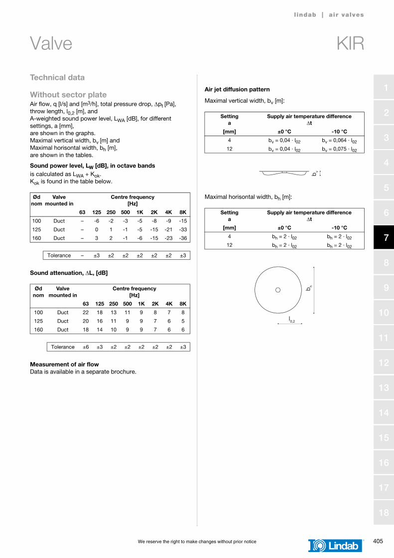
Valve KIR
l indab | air valves
DescriptionValve for supply air.Designed for ceiling mounting. Equipped with a removable blanking-off sector plate for preventing the air flow in a desired direction.Bayonet holders connect to socket VRGU, VRGL or VRGM.
Materials and finishMaterialPainted galvanized sheet metal.
ColourWhite RAL 9010, gloss 70, equivalent to NCS S 0502 Y.
MaintenanceThe visible parts can be wiped with a damp cloth.
Dimensions
Ordering exampleKIR 100
ProductDimension Ød
Ødnom
ØDmm
mkg
100 135 0,28
125 165 0,44
160 205 0,62
ØD
Ød
KIR
We reserve the right to make changes without prior notice 405
1
2
3
4
5
6
7
8
9
10
11
12
13
14
15
16
17
18
Valve KIR
l indab | air valves
Technical data
Without sector plateAir flow, q [l/s] and [m3/h], total pressure drop, Δpt [Pa], throw length, l0,2 [m], andA-weighted sound power level, LWA [dB], for differentsettings, a [mm], are shown in the graphs.Maximal vertical width, bv [m] and Maximal horisontal width, bh [m], are shown in the tables.
Sound power level, LW [dB], in octave bandsis calculated as LWA + Kok.Kok is found in the table below.
Sound attenuation, ΔL, [dB]
Measurement of air flowData is available in a separate brochure.
Air jet diffusion pattern
Maximal vertical width, bv [m]:
Maximal horisontal width, bh [m]:Ødnom
Valve mounted in
Centre frequency [Hz]
63 125 250 500 1K 2K 4K 8K
100 Duct – -6 -2 -3 -5 -8 -9 -15
125 Duct – 0 1 -1 -5 -15 -21 -33
160 Duct – 3 2 -1 -6 -15 -23 -36
Tolerance – ±3 ±2 ±2 ±2 ±2 ±2 ±3
Ødnom
Valve mounted in
Centre frequency [Hz]
63 125 250 500 1K 2K 4K 8K
100 Duct 22 18 13 11 9 8 7 8
125 Duct 20 16 11 9 9 7 6 5
160 Duct 18 14 10 9 9 7 6 6
Tolerance ±6 ±3 ±2 ±2 ±2 ±2 ±2 ±3
Settinga
Supply air temperature differenceΔt
[mm] ±0 °C -10 °C
4 bv = 0,04 · l02 bv = 0,064 · l02
12 bv = 0,04 · l02 bv = 0,075 · l02
Settinga
Supply air temperature differenceΔt
[mm] ±0 °C -10 °C
4 bh = 2 · l02 bh = 2 · l02
12 bh = 2 · l02 bh = 2 · l02
bv
l0,2
b h
406 We reserve the right to make changes without prior notice
1
2
3
4
5
6
7
8
9
10
11
12
13
14
15
16
17
18
Valve KIR
l indab | air valves
10
20
50
100
5 10 20 50 [l/s]
Δ p
t [P
a]
20
q
50 100 180 [m3/h]
Ø 100
200
30 40
LWA [dB(A)]
l0,2 [m]
a [mm]2 4 6
9
12
1,0
1,5
2,0 2,5
30
35
40
10
20
50
100
5 10 20 80 [l/s]
Δ p
t [P
a]
20
q
50 100 200 [m3/h]
Ø 125
200
30 40 50
LWA [dB(A)]
l0,2 [m]
a [mm]4 6 9
12
15
1,5
2,0
2,5
3,03,5
30
35
40
10
20
50
100
10 15 20 130 [l/s]
Δ p
t [P
a]
40
q
100 200 300 [m3/h]
Ø 160200
30 40 50
400
100
LWA [dB(A)]
l0,2 [m]
a [mm]
4 6 10 15
20
1,5
2,0
2,5 3,0
30
35
40
We reserve the right to make changes without prior notice 407
1
2
3
4
5
6
7
8
9
10
11
12
13
14
15
16
17
18
Valve KIR
l indab | air valves
Technical data
With sector plateAir flow, q [l/s] and [m3/h], total pressure drop, Δpt [Pa], throw length, l0,2 [m], andA-weighted sound power level, LWA [dB], for differentsettings, a [mm], are shown in the graphs.Maximal vertical width, bv [m] and Maximal horisontal width, bh [m], are shown in the tables.
Sound power level, LW [dB], in octave bandsis calculated as LWA + Kok.Kok is found in the table below.
Sound attenuation, ΔL, [dB]
Measurement of air flowData is available in a separate brochure.
Air jet diffusion pattern
Maximal vertical width, bv [m]:
Maximal horisontal width, bh [m]:Ødnom
Valve mounted in
Centre frequency [Hz]
63 125 250 500 1K 2K 4K 8K
100 Duct – -2 -2 -4 -6 -8 -8 -16
125 Duct – -1 -1 -1 -4 -12 -19 -33
160 Duct – 3 0 -2 -5 -10 -21 -35
Tolerance – ±3 ±2 ±2 ±2 ±2 ±2 ±3
Ødnom
Valve mounted in
Centre frequency [Hz]
63 125 250 500 1K 2K 4K 8K
100 Duct 22 18 13 11 9 8 7 8
125 Duct 20 16 11 9 9 7 6 5
160 Duct 18 14 10 9 9 7 6 6
Tolerance ±6 ±3 ±2 ±2 ±2 ±2 ±2 ±3
Settinga
Supply air temperature differenceΔt
[mm] ±0 °C -10 °C
4 bv = 0,04 · l02 bv = 0,064 · l02
12 bv = 0,04 · l02 bv = 0,075 · l02
Settinga
Supply air temperature differenceΔt
[mm] ±0 °C -10 °C
4 bh = 1,45 · l02 bh = 1,15 · l02
12 bh = 1,45 · l02 bh = 1,09 · l02
bv
l0,2
b h
408 We reserve the right to make changes without prior notice
1
2
3
4
5
6
7
8
9
10
11
12
13
14
15
16
17
18
Valve KIR
l indab | air valves
10
20
50
100
5 10 20 50 [l/s]
Δ p
t [P
a]
20
q
50 100 180 [m3/h]
Ø 100
200
30 40
LWA [dB(A)]
l0,2 [m]
a [mm]2 4 6 9 12
30
35
40
1,5
1,0
2
3 4 5
10
20
50
100
5 10 20 80 [l/s]
Δ p
t [P
a]
20
q
50 100 200 [m3/h]
Ø 125
200
30 40 50
LWA [dB(A)]
l0,2 [m]
a [mm]4 6 9 1215
30
35
40
1,5
2
3
4
10
20
50
100
10 15 20 130 [l/s]
Δ p
t [P
a]
40
q
100 200 300 [m3/h]
Ø 160200
30 40 50
400
100
LWA [dB(A)]
l0,2 [m]
a [mm]
4 6 10 15 20
30
35
40
1,5
2
4 5
3
We reserve the right to make changes without prior notice 409
1
2
3
4
5
6
7
8
9
10
11
12
13
14
15
16
17
18
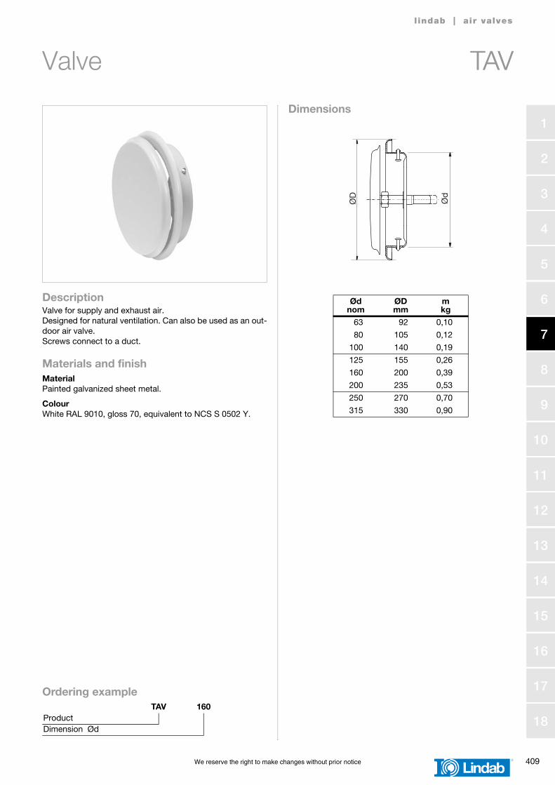
Valve TAV
l indab | air valves
DescriptionValve for supply and exhaust air.Designed for natural ventilation. Can also be used as an out-door air valve.Screws connect to a duct.
Materials and finishMaterialPainted galvanized sheet metal.
ColourWhite RAL 9010, gloss 70, equivalent to NCS S 0502 Y.
Dimensions
Ordering exampleTAV 160
ProductDimension Ød
Ødnom
ØDmm
mkg
63 92 0,10
80 105 0,12
100 140 0,19
125 155 0,26
160 200 0,39
200 235 0,53
250 270 0,70
315 330 0,90
Ød
ØD
TAV
410 We reserve the right to make changes without prior notice
1
2
3
4
5
6
7
8
9
10
11
12
13
14
15
16
17
18
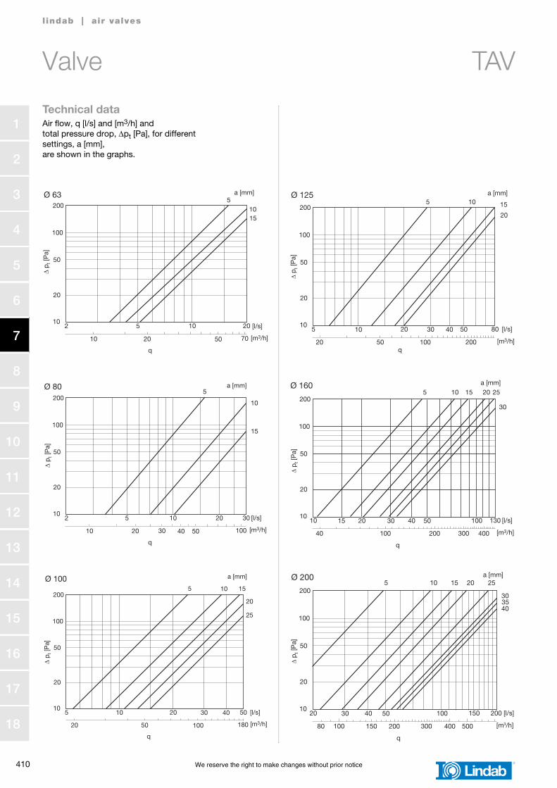
Valve TAV
l indab | air valves
Technical dataAir flow, q [l/s] and [m3/h] and total pressure drop, Δpt [Pa], for different settings, a [mm], are shown in the graphs.
10
20
50
100
2 5 10 20 [l/s]
Δ p
t [P
a]
10
q
20 50 70 [m3/h]
Ø 63200
51015
a [mm]
10
20
50
100
5 10 20 80 [l/s]
Δ p
t [P
a]
20q
50 100 200 [m3/h]
Ø 125200
30 40 50
5 10 15
20
a [mm]
10
20
50
100
2 5 10 30 [l/s]
Δ p
t [P
a]
10
q
20 50 100 [m3/h]
Ø 80200
20
30 40
5
10
15
a [mm]
10
20
50
100
5 10 20 50 [l/s]
Δ p t
[Pa]
20
q
50 100 180 [m3/h]
Ø 100
200
30 40
5 10 15
20
25
a [mm]
10
20
50
100
10 15 20 130 [l/s]
Δ p
t [P
a]
40
q
100 200 300 [m3/h]
Ø 160
200
30 40 50
400
100
5 10 15 20 25
30
a [mm]
10
20
50
100
20 30 40 150 [l/s]
Δ p
t [P
a]
80
q
150 200 300 [m3/h]
Ø 200
200
50 100
400
200
100 500
5 10 15 20 25
303540
a [mm]
We reserve the right to make changes without prior notice 411
1
2
3
4
5
6
7
8
9
10
11
12
13
14
15
16
17
18
Valve TAV
l indab | air valves
10
20
50
100
20 30 40 150 [l/s]
Δ p
t [P
a]
80
q
150 200 300 [m3/h]
Ø 250
200
50 100
400
200
100 500
300
1000
5 10 15 20 25 30a [mm]
10
20
50
100
50 [l/s]
Δ p
t [P
a]
200
q
500 [m3/h]
Ø 315
200
100 200 300
300 1000
500
1500
400
5 10 15 20 25 30a [mm]
412 We reserve the right to make changes without prior notice
1
2
3
4
5
6
7
8
9
10
11
12
13
14
15
16
17
18
Valve KVB
l indab | air valves
DescriptionValve for exhaust air.Designed for wall or ceiling mounting.Spring holders connect to socket VRFU, VRFM or VRR.
Materials and finishMaterialPainted galvanized sheet metal.
ColourWhite RAL 9010, gloss 70, equivalent to NCS S 0502 Y.
Dimensions
Ordering exampleKVB 125
ProductDimension Ød
Ødnom
ØDmm
mkg
100 125 0,27
125 150 0,36
160 190 0,54Ø
D
Ød
KVB
We reserve the right to make changes without prior notice 413
1
2
3
4
5
6
7
8
9
10
11
12
13
14
15
16
17
18
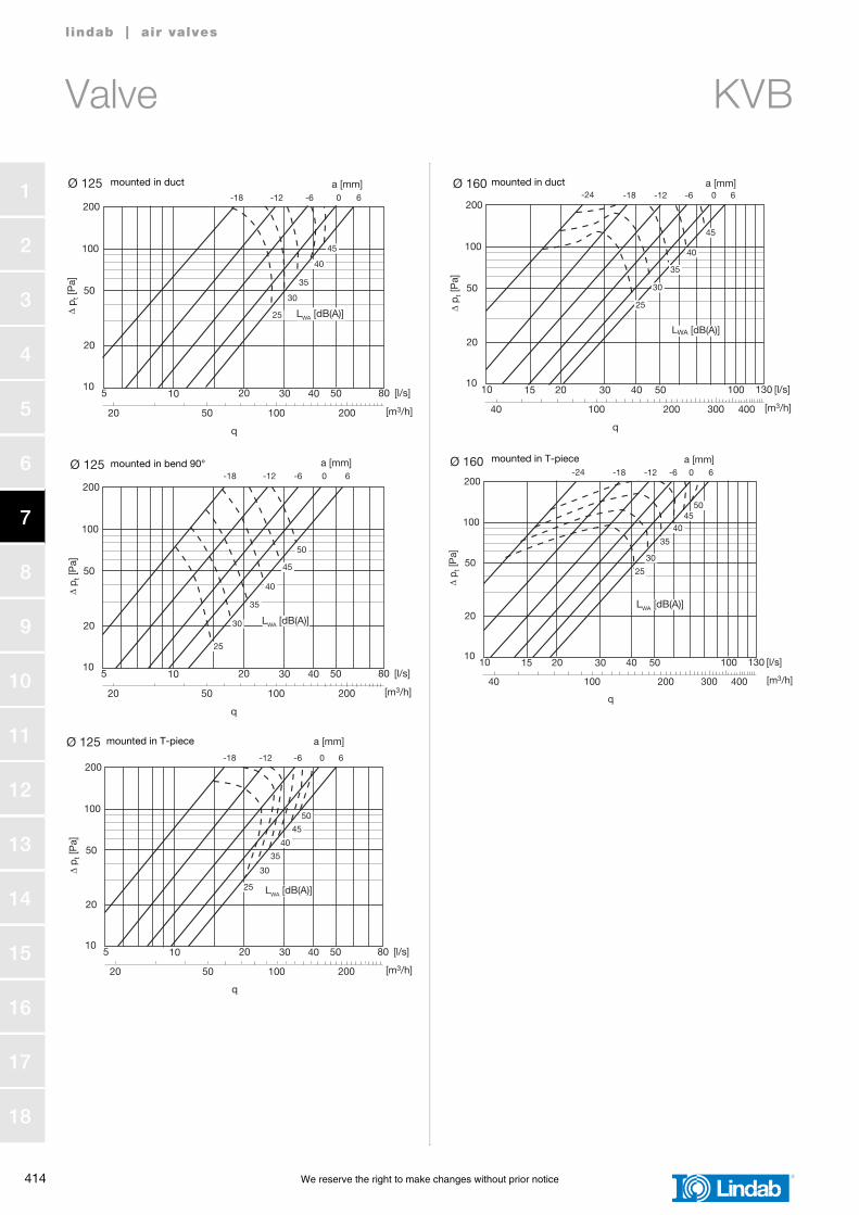
Valve KVB
l indab | air valves
Technical dataAir flow, q [l/s] and [m3/h],total pressure drop, Δpt [Pa], andA-weighted sound power level, LWA [dB], for differentsettings, a [mm],are shown in the graphs.
Sound power level, LW [dB], in octave bandsis calculated as LWA + Kok.Kok is found in the table below.
Sound attenuation, ΔL, [dB]
Measurement of air flowData is available in a separate brochure.
Ødnom
Valve mounted in
Centre frequency [Hz]
63 125 250 500 1K 2K 4K 8K
100Duct
Bend 90°T-piece
666
222
111
-3-3-3
-6-6-6
-8-8-8
-11-11-11
-16-16-16
125Duct
Bend 90°T-piece
131313
-2-2-2
-1-1-1
-5-5-5
-5-5-5
-8-8-8
-12-12-12
-16-16-16
160Duct
T-piece1414
00
-1-1
-4-4
-3-3
-8-8
-16-16
-18-18
Ødnom
Valve mounted in
Centre frequency [Hz]
63 125 250 500 1K 2K 4K 8K
100Duct
Bend 90°T-piece
253025
222722
212321
201720
141614
181918
9129
101310
125Duct
Bend 90°T-piece
242924
202520
171917
151215
111311
121312
7107
7107
160Duct
T-piece2222
1818
1616
1212
1414
1010
99
88
10
20
50
100
5 10 20 50 [l/s]
Δ p t
[Pa]
20
q
50 100 180 [m3/h]
Ø 100
200
30 40
25
LWA [dB(A)]
30
35
40
a [mm]-11 -9 -6 0 6
mounted in duct
10
20
50
100
5 10 20 50 [l/s]
Δ p t
[Pa]
20
q
50 100 180 [m3/h]
Ø 100
200
30 40
a [mm]
25
30
35
40
45
-11 -9 -6 0 6
LWA [dB(A)]
mounted in bend 90°
10
20
50
100
5 10 20 50 [l/s]
Δ p t
[Pa]
20
q
50 100 180 [m3/h]
Ø 100
200
30 40
25
30
35
40
LWA [dB(A)]
-11 -9 -6 0 6a [mm]mounted in T-piece
414 We reserve the right to make changes without prior notice
1
2
3
4
5
6
7
8
9
10
11
12
13
14
15
16
17
18
Valve KVB
l indab | air valves
10
20
50
100
5 10 20 80 [l/s]
Δ p t
[Pa]
20
q
50 100 200 [m3/h]
Ø 125
200
30 40 50
a [mm]
LWA [dB(A)]25
30
35
40
45
-18 -12 -6 0 6
mounted in duct
10
20
50
100
5 10 20 80 [l/s]
Δ p t
[Pa]
20
q
50 100 200 [m3/h]
Ø 125
200
30 40 50
a [mm]
LWA [dB(A)]
25
30
35
40
45
50
-18 -12 -6 0 6mounted in bend 90°
10
20
50
100
5 10 20 80 [l/s]
Δ p t
[Pa]
20
q
50 100 200 [m3/h]
Ø 125
200
30 40 50
a [mm]
LWA [dB(A)]25
30
35
40
45
50
-18 -12 -6 0 6
mounted in T-piece
10
20
50
100
10 15 20 130 [l/s]
Δ p t
[Pa]
40
q
100 200 300 [m3/h]
Ø 160
200
30 40 50
400
100
a [mm]
25
30
35
40
45
-24 -18 -12 -6 0 6
LWA [dB(A)]
mounted in duct
10
20
50
100
10 15 20 130 [l/s]
Δ p t
[Pa]
40
q
100 200 300 [m3/h]
Ø 160
200
30 40 50
400
100
a [mm]
25
30
35
4045
-24 -18 -12 -6 0 6
50
LWA [dB(A)]
mounted in T-piece
We reserve the right to make changes without prior notice 415
1
2
3
4
5
6
7
8
9
10
11
12
13
14
15
16
17
18
Exhaust valve KVG
l indab | air valves
DescriptionValve for exhaust air.Designed for wall or ceiling mounting.Ø 100–160 have spring holders which connect to socket VRFU, VRFM or VRR.Ø 200 has bayonet holders which connect to socket VRGU, VRGL or VRGM.
Materials and finishMaterialPainted galvanized sheet metal.
ColourWhite RAL 9010, gloss 70, equivalent to NCS S 0502 Y.
Dimensions
Ordering exampleKVG 100
ProductDimension Ød
Ødnom
ØDmm
mkg
100 132 0,18
125 162 0,25
160 192 0,37
200 243 0,59
l
ØD
KVG
416 We reserve the right to make changes without prior notice
1
2
3
4
5
6
7
8
9
10
11
12
13
14
15
16
17
18
Exhaust valve KVG
l indab | air valves
Technical dataAir flow, q [l/s] and [m3/h],total pressure drop, Δpt [Pa], andA-weighted sound power level, LWA [dB], for differentsettings, a [mm],are shown in the graphs.
Sound power level, LW [dB], in octave bandsis calculated as LWA + Kok.Kok is found in the table below.
Sound attenuation, ΔL, [dB]
Measurement of air flowData is available in a separate brochure.
Ødnom
Valve mounted in
Centre frequency [Hz]
63 125 250 500 1K 2K 4K 8K
100Duct
Bend 90°T-piece
4-17
-4-10
-6-3-2
-7-3-7
-6-5-6
-4-7-5
-13-16-11
-18-27-21
125Duct
T-piece67
-10
-3-2
-6-7
-7-6
-4-5
-16-13
-27-24
160Duct
T-piece55
-51
-4-5
-6-8
-3-6
-7-4
-18-18
-30-29
200 Duct 3 -2 -5 -6 -2 -9 -16 -26
Tolerance ±6 ±3 ±2 ±2 ±2 ±2 ±2 ±3
Ødnom
Valve mounted in
Settinga
[mm]
Centre frequency [Hz]
63 125 250 500 1K 2K 4K 8K
100
Duct-1208
232222
191616
1499
1487
1265
1165
1364
16108
Bend 90°-1208
252424
201717
151111
1376
1265
1275
1265
151111
T-piece-1208
232222
191616
1499
1487
1265
1165
1364
16108
125 Duct-17-65
212019
151414
12109
1076
854
854
1164
1478
160 Duct-1856
191818
141312
1087
865
754
954
131010
1386
200 Duct-200
20
171715
141212
976
855
853
1064
1188
1287
10
20
50
100
5 10 20 50 [l/s]
Δ p t
[Pa]
20
q
50 100 180 [m3/h]
Ø 100
200
30 40
a [mm]
30
35
40
-9 -5 0 5
8
12
LWA [dB(A)]
mounted in duct
10
20
50
100
5 10 20 50 [l/s]
Δ p t
[Pa]
20
q
50 100 180 [m3/h]
Ø 100
200
30 40
a [mm]
25
30
35
40
-9 -5 0 5 8
12
LWA [dB(A)]
mounted in bend 90°
10
20
50
100
5 10 20 50 [l/s]
Δ p t
[Pa]
20
q
50 100 180 [m3/h]
Ø 100
200
30 40
a [mm]
25
30
35
40
45
-9 -5 0 5
8
12
LWA [dB(A)]
mounted in T-piece
We reserve the right to make changes without prior notice 417
1
2
3
4
5
6
7
8
9
10
11
12
13
14
15
16
17
18
Exhaust valve KVG
l indab | air valves
10
20
50
100
5 10 20 80 [l/s]
Δ p t
[Pa]
20
q
50 100 200 [m3/h]
Ø 125
200
30 40 50
a [mm]
30
35
40
-17 -13 -9 -6 -3 0 5
10
1545
LWA [dB(A)]
mounted in duct
10
20
50
100
5 10 20 80 [l/s]
Δ p t
[Pa]
20
q
50 100 200 [m3/h]
Ø 125
200
30 40 50
a [mm]
25
30
35
40
-17 -13 -9-6
-3 0 5 10
15
45
LWA [dB(A)]
mounted in T-piece
10
20
50
100
10 15 20 130 [l/s]
Δ p t
[Pa]
40
q
100 200 300 [m3/h]
Ø 160
200
30 40 50
400
100
a [mm]
25
30
35
40
-18 -14 -10 -5 0 6 12
18
LWA [dB(A)]
mounted in duct
10
20
50
100
10 15 20 130 [l/s]
Δ p t
[Pa]
40
q
100 200 300 [m3/h]
Ø 160
200
30 40 50
400
100
a [mm]
25
30
35
40
-18 -14 -10 -5 0 6 1218
45
LWA [dB(A)]
mounted in T-piece
10
20
50
100
20 30 40 150 [l/s]
Δ p t
[Pa]
80
q
150 200 300 [m3/h]
Ø 200
200
50 100
400
200
100 500
a [mm]
25
30
35
40
45
-23 -18 -15 -10 -5 0 10
20
LWA [dB(A)]
mounted in duct
418 We reserve the right to make changes without prior notice
1
2
3
4
5
6
7
8
9
10
11
12
13
14
15
16
17
18
Exhaust valve KU
l indab | air valves
DescriptionValve for exhaust air.Designed for wall or ceiling mounting.Bayonet holders connect to socket VRGU, VRGL or VRGM.
Materials and finishMaterialPainted galvanized sheet metal.
ColourWhite RAL 9010, gloss 70, equivalent to NCS S 0502 Y.
Dimensions
Ordering exampleKU 125
ProductDimension Ød
Ødnom
ØDmm
mkg
80 110 0,13
100 130 0,19
125 160 0,27
150 188 0,36
160 190 0,38
200 245 0,58
Ød
ØD
KU
We reserve the right to make changes without prior notice 419
1
2
3
4
5
6
7
8
9
10
11
12
13
14
15
16
17
18
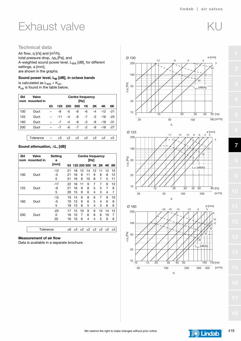
Exhaust valve KU
l indab | air valves
Technical dataAir flow, q [l/s] and [m3/h],total pressure drop, Δpt [Pa], andA-weighted sound power level, LWA [dB], for differentsettings, a [mm],are shown in the graphs.
Sound power level, LW [dB], in octave bandsis calculated as LWA + Kok.Kok is found in the table below.
Sound attenuation, ΔL, [dB]
Measurement of air flowData is available in a separate brochure.
Ødnom
Valve mounted in
Centre frequency [Hz]
63 125 250 500 1K 2K 4K 8K
100 Duct – -8 -5 -6 -6 -4 -12 -21
125 Duct – -11 -4 -6 -7 -3 -16 -25
160 Duct – -7 -4 -6 -3 -6 -18 -31
200 Duct – -7 -6 -7 -2 -9 -18 -27
Tolerance – ±3 ±2 ±2 ±2 ±2 ±2 ±3
Ødnom
Valve mounted in
Settinga
[mm]
Centre frequency [Hz]
63 125 250 500 1K 2K 4K 8K
100 Duct-12-55
212121
181616
1298
141110
1298
1187
1285
151211
125 Duct-17-95
222120
161615
1199
986
754
753
974
1287
160 Duct-15-55
191918
141313
998
865
654
743
966
1086
200 Duct-250
20
171616
121010
1076
964
964
1265
14109
1276
Tolerance ±6 ±3 ±2 ±2 ±2 ±2 ±2 ±3
10
20
50
100
5 10 20 50 [l/s]
Δ p t
[Pa]
20
q
50 100 180 [m3/h]
Ø 100200
30 40
LWA [dB(A)]
a [mm]
30
35
40
-12 -9 -5 05
10
20
50
100
5 10 20 80 [l/s]
Δ p
t [P
a]
20
q
50 100 200 [m3/h]
Ø 125200
30 40 50
LWA [dB(A)]
a [mm]
30
35
40
-17 -15 -12 -9 -6 -3 0
5
10
20
50
100
10 15 20 130 [l/s]
Δ p t
[Pa]
40
q
100 200 300 [m3/h]
Ø 160200
30 40 50
400
100
LWA [dB(A)]
a [mm]
30
35
40
-20 -18 -15 -10 -5 0
6
10
12
420 We reserve the right to make changes without prior notice
1
2
3
4
5
6
7
8
9
10
11
12
13
14
15
16
17
18
Exhaust valve KU
l indab | air valves
10
20
50
100
20 30 40 150 [l/s]
Δ p
t [P
a]
80
q
150 200 300 [m3/h]
Ø 200200
50 100
400
200
100 500
LWA [dB(A)]
a [mm]
30
35
40
-25 -20 -15 -10 -5 0 10
20
We reserve the right to make changes without prior notice 421
1
2
3
4
5
6
7
8
9
10
11
12
13
14
15
16
17
18
Exhaust valve KSU
l indab | air valves
DescriptionValve for exhaust air.Designed for wall or ceiling mounting.Bayonet holders connect to socket VRGU, VRGL, or VRGM.
Materials and finishMaterialPainted galvanized sheet metal.
ColourWhite RAL 9010, gloss 70, equivalent to NCS S 0502 Y.
Dimensions
Ordering exampleKSU 160
ProductDimension Ød
Ødnom
ØDmm
mkg
100 130 0,30
125 160 0,39
150 188 0,52
160 190 0,52
200 235 0,78
ØD Ø
d
KSU
422 We reserve the right to make changes without prior notice
1
2
3
4
5
6
7
8
9
10
11
12
13
14
15
16
17
18
Exhaust valve KSU
l indab | air valves
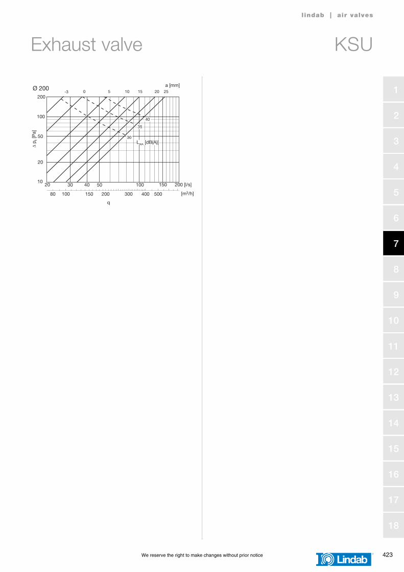
Technical dataAir flow, q [l/s] and [m3/h], total pressure drop, Δpt [Pa], andA-weighted sound power level, LWA [dB], for differentsettings, a [mm],are shown in the graphs.
Sound power level, LW [dB], in octave bandsis calculated as LWA + Kok.Kok is found in the table below.
Sound attenuation, ΔL, [dB]
Measurement of air flowData is available in a separate brochure.
We reserve the right to make changes without prior notice 423
1
2
3
4
5
6
7
8
9
10
11
12
13
14
15
16
17
18
Exhaust valve KSU
l indab | air valves
10
20
50
100
20 30 40 150 [l/s]
Δ p t
[Pa]
80
q
150 200 300 [m3/h]
Ø 200200
50 100
400
200
100 500
a [mm]
30
35
40
-3 0 5 10 15 20 25
LWA [dB(A)]
424 We reserve the right to make changes without prior notice
1
2
3
4
5
6
7
8
9
10
11
12
13
14
15
16
17
18
Valve and fire damper KSUB
l indab | air valves
DescriptionValve and fire damper for exhaust air.Is used to prevent spreading of fire and smoke into duct systems. A spring loaded melting fuse shuts the valve when the temperature exceeds +70° C.Bayonet holders connect to socket VRGU, VRGL or VRGM.Socket VRGL is as standard delivered together with KSUB. This case is shown in the ordering example below.If socket VRGU or VRGM is wanted instead this socket has to be specified in the type field.The product holds a Swedish type approval with number 0901. Certification body is Swedcert.
Materials and finishMaterialPainted galvanized sheet metal.
ColourWhite RAL 9010, gloss 70, equivalent to NCS S 0502 Y.
MaintenanceThe visible parts can be wiped with a damp cloth.
Dimensions
Fire class without protective distance
Fire class with protective distanceThe valve´s surface may not be altered, e.g. by painting.
We reserve the right to make changes without prior notice 425
1
2
3
4
5
6
7
8
9
10
11
12
13
14
15
16
17
18
Valve and fire damper KSUB
l indab | air valves
Technical dataAir flow, q [l/s] and [m3/h],total pressure drop, Δpt [Pa], andA-weighted sound power level, LWA [dB], for differentsettings, a [mm],are shown in the graphs.
Sound power level, LW [dB], in octave bandsis calculated as LWA + Kok.Kok is found in the table below.
Sound attenuation, ΔL, [dB]
Measurement of air flowData is available in a separate brochure.
Ødnom
Valve mounted in
Centre frequency [Hz]
63 125 250 500 1K 2K 4K 8K
100 Duct – -2 -5 -5 -3 -8 -12 -26
125 Duct – -7 -7 -7 -6 -4 -11 -28
160 Duct – -4 -7 -5 -2 -11 -15 -29
200 Duct – -3 -7 -8 -1 -12 -16 -33
Tolerance – ±3 ±2 ±2 ±2 ±2 ±2 ±3
Ødnom
Valve mounted in
Settinga
[mm]
Centre frequency [Hz]
63 125 250 500 1K 2K 4K 8K
100 Duct-100
10
222222
191817
161312
16129
16128
181311
964
976
125 Duct-100
10
211920
181716
151210
14119
15119
14108
1065
755
160 Duct-100
10
191818
161414
141110
14119
14119
161311
854
876
200 Duct0
101413
1211
118
108
129
1210
76
76
Tolerance ±6 ±3 ±2 ±2 ±2 ±2 ±2 ±3
10
20
50
100
5 10 20 50 [l/s]
Δ p t
[Pa]
20
q
50 100 180 [m3/h]
Ø 100200
30 40
LWA [dB]
a [mm]
30
35
40
-15 -12 -10 -5 0 510
10
20
50
100
5 10 20 80 [l/s]
Δ p
t [P
a]
20
q
50 100 200 [m3/h]
Ø 125200
30 40 50
LWA [dB]
a [mm]
30
35
40
-10 -5 0 5 10
10
20
50
100
10 15 20 130 [l/s]
Δ p t
[Pa]
40
q
100 200 300 [m3/h]
Ø 160200
30 40 50
400
100
LWA [dB]
a [mm]
25
30
35
-10 -5 0 5 10 15
426 We reserve the right to make changes without prior notice
1
2
3
4
5
6
7
8
9
10
11
12
13
14
15
16
17
18
Valve and fire damper KSUB
l indab | air valves
10
20
50
100
20 30 40 150 [l/s]
Δ p t
[Pa]
80
q
150 200 300 [m3/h]
Ø 200200
50 100
400
200
100 500
LWA [dB]
a [mm]
30
35
40
-3 0 5 10 15
We reserve the right to make changes without prior notice 427
1
2
3
4
5
6
7
8
9
10
11
12
13
14
15
16
17
18
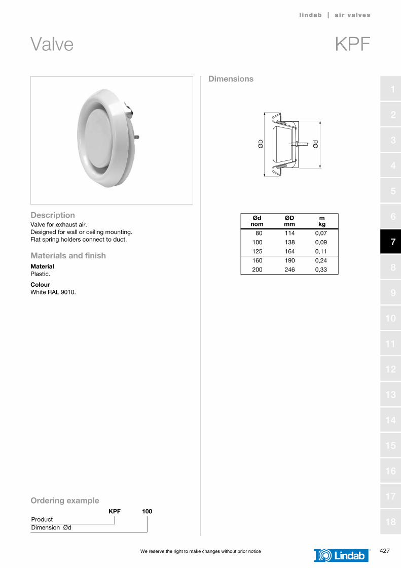
Valve KPF
l indab | air valves
DescriptionValve for exhaust air.Designed for wall or ceiling mounting.Flat spring holders connect to duct.
Materials and finishMaterialPlastic.
ColourWhite RAL 9010.
Dimensions
Ordering exampleKPF 100
ProductDimension Ød
Ødnom
ØDmm
mkg
80 114 0,07
100 138 0,09
125 164 0,11
160 190 0,24
200 246 0,33
Ød
ØD
KPF
428 We reserve the right to make changes without prior notice
1
2
3
4
5
6
7
8
9
10
11
12
13
14
15
16
17
18
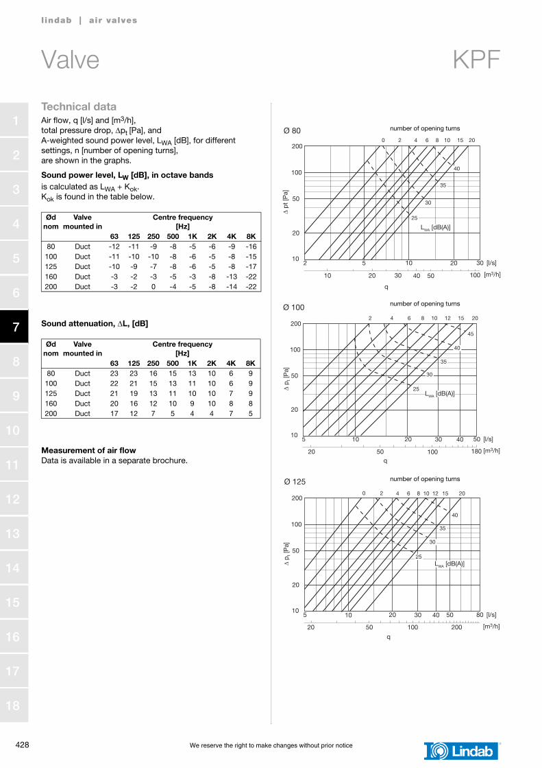
Valve KPF
l indab | air valves
Technical dataAir flow, q [l/s] and [m3/h],total pressure drop, Δpt [Pa], andA-weighted sound power level, LWA [dB], for differentsettings, n [number of opening turns],are shown in the graphs.
Sound power level, LW [dB], in octave bandsis calculated as LWA + Kok.Kok is found in the table below.
Sound attenuation, ΔL, [dB]
Measurement of air flowData is available in a separate brochure.
We reserve the right to make changes without prior notice 429
1
2
3
4
5
6
7
8
9
10
11
12
13
14
15
16
17
18
Valve KPF
l indab | air valves
10
20
50
100
10 15 20 130 [l/s]
Δ p t
[Pa]
40
q
100 200 300 [m3/h]
Ø 160
200
30 40 50
400
100
30
35
40
45
50
25
6 8 10 15 20
25
LWA [dB(A)]
number of opening turns
10
20
50
100
20 30 40 150 [l/s]
Δ p t
[Pa]
80
q
150 200 300 [m3/h]
Ø 200
200
50 100
400
200
100 500
30
35
40
45
50
2 4 6 8 10 12 15
LWA [dB(A)]
number of opening turns
430 We reserve the right to make changes without prior notice
1
2
3
4
5
6
7
8
9
10
11
12
13
14
15
16
17
18
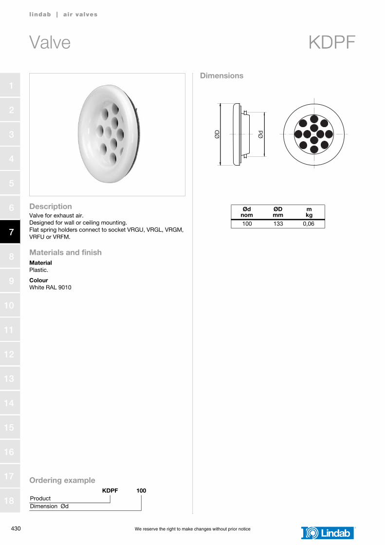
Valve KDPF
l indab | air valves
DescriptionValve for exhaust air.Designed for wall or ceiling mounting.Flat spring holders connect to socket VRGU, VRGL, VRGM, VRFU or VRFM.
Materials and finishMaterialPlastic.
ColourWhite RAL 9010
Dimensions
Ordering exampleKDPF 100
ProductDimension Ød
Ødnom
ØDmm
mkg
100 133 0,06Ø
D
Ød
KDPF
We reserve the right to make changes without prior notice 431
1
2
3
4
5
6
7
8
9
10
11
12
13
14
15
16
17
18
Valve KDPF
l indab | air valves
Technical dataAir flow, q [l/s] and [m3/h],total pressure drop, Δpt [Pa], andA-weighted sound power level, LWA [dB], for differentsettings, n [number of open holes],are shown in the graphs.
Measurement of air flowData is available in a separate brochure.
Sound power level, LW [dB], in octave bandsis calculated as LWA + Kok. Kok is found in the table below.