Page 1
Roland Ritter, Linde-K C A Dresden G mbH Yeppoon, 2nd Oxyfuel C ombustion C onference, S eptemper 14th 2011, plenary sess ion 3
LINDE’s activities for design and development of the CO2 processing unit in the Oxyfuel power plant
Page 2
Linde-K C A Dres den G mbH 2. Oxyfuel C ombus tion C onference – S es s ion 3 plenary s es s ion / 14. S eptember 2011
2
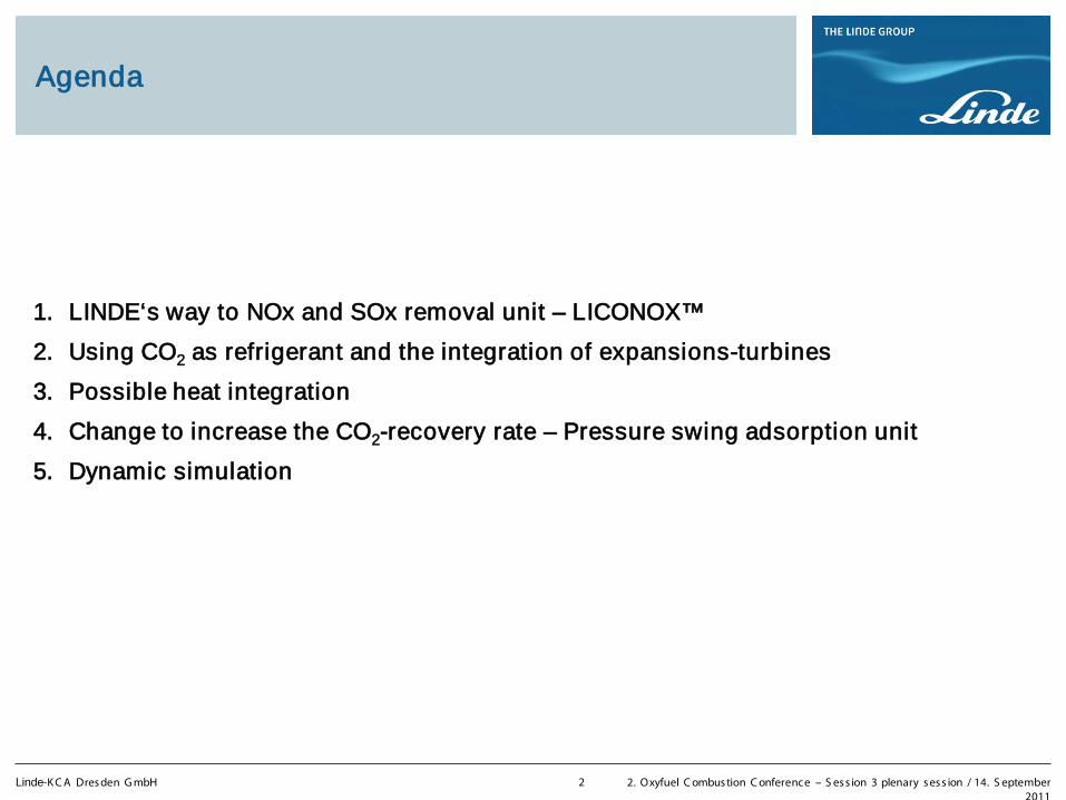
Agenda
1. LINDE‘s way to NOx and SOx removal unit – LICONOX™
2. Using CO2 as refrigerant and the integration of expansions-turbines
3. Possible heat integration
4. Change to increase the CO2-recovery rate – Pressure swing adsorption unit
5. Dynamic simulation
Page 3
Linde-K C A Dres den G mbH 2. Oxyfuel C ombus tion C onference – S es s ion 3 plenary s es s ion / 14. S eptember 2011
3
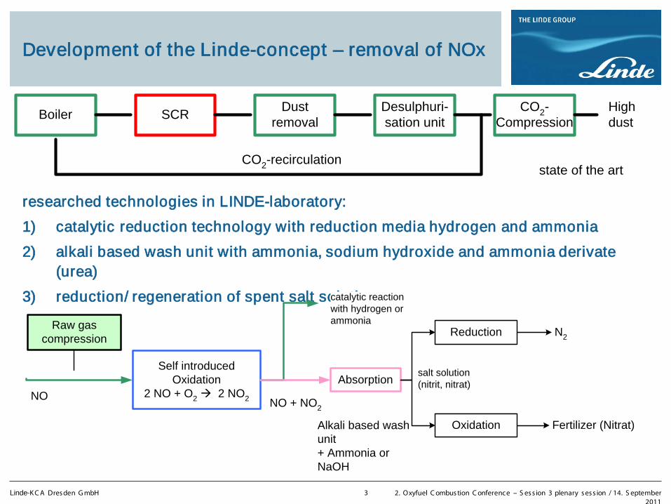
Development of the Linde-concept – removal of NOx
researched technologies in LINDE-laboratory:
1) catalytic reduction technology with reduction media hydrogen and ammonia
2) alkali based wash unit with ammonia, sodium hydroxide and ammonia derivate (urea)
3) reduction/ regeneration of spent salt solution
CO2-recirculation
Boiler High dust
SCRDust
removalDesulphuri-sation unit
CO2-Compression
state of the art
Raw gascompression
Self introducedOxidation
2 NO + O2 2 NO2NO
Reduction
Absorption
Alkali based washunit+ Ammonia orNaOH
Fertilizer (Nitrat)
N2
NO + NO2
Oxidation
catalytic reactionwith hydrogen orammonia
salt solution(nitrit, nitrat)
Page 4
Linde-K C A Dres den G mbH 2. Oxyfuel C ombus tion C onference – S es s ion 3 plenary s es s ion / 14. S eptember 2011
4
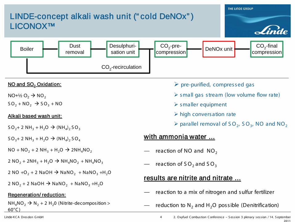
LINDE-concept alkali wash unit (“ cold DeNOx” ) LICONOX™
NO and SO2 Oxidation:
NO+½ O2 NO 2
S O 2 + NO 2 S O 3 + NO
Alkali based wash unit:
S O 2+ 2 NH3 + H2O (NH4)2 S O 3
S O 3+ 2 NH3 + H2O (NH4)2 S O 4
NO + NO 2 + 2 NH3 + H2O 2NH4NO 2
2 NO 2 + 2NH3 + H2O NH4NO 2 + NH4NO 3
2 NO +O 2 + 2 NaOH NaNO 2 + NaNO 3 +H2O
2 NO 2 + 2 NaOH NaNO 2 + NaNO 3 +H2O
Regeneration/ reduction:
NH4NO 2 N2 + 2 H20 (Nitrite-decomposition > 60°C )
with ammonia water …
— reaction of NO and NO2
— reaction of S O2 and S O3
results are nitrite and nitrate …
— reaction to a mix of nitrogen and sulfur fertilizer
— reduction to N2 and H2O poss ible (Denitrification)
Boiler DeNOx unitDust
removalDesulphuri-sation unit
CO2-pre-compression
CO2-recirculation
CO2-finalcompression
pre-purified, compressed gas
small gas s tream (low volume flow rate)
smaller equipment
high conversation rate
parallel removal of S O2, S O3, NO and NO2
Page 5
Linde-K C A Dres den G mbH 2. Oxyfuel C ombus tion C onference – S es s ion 3 plenary s es s ion / 14. S eptember 2011
5
Test phase on the alkali wash unit
simple process flow diagram
FC
PC
AC
TCAI
M
M
FI
FI
LC
FC
AI
TI
AI
SC
SC
4 x
7 x
Kühlwasser
Make-up Wasser
Ammoniak-wasser
Abwasser
Rauchgas
gereinigtesRauchgas
PDI
PDI
TI
TC
AI
T701
P701
E701
P702
P703
D701
M
pH
NOx
first test phase:
27.07. – 07.09.2010 using ammonia water
laboratory results confirmed
second test phase:
26.04. – 27.05.2011
(1) reduction of spent salt solution
(2) using sodium hydroxide
Page 6
Linde-K C A Dres den G mbH 2. Oxyfuel C ombus tion C onference – S es s ion 3 plenary s es s ion / 14. S eptember 2011
6
LICONOX™ - results of pilot plant
Simulat ion and Comparison with measured Data10bar; 24°C; 6,5vol% O2; pH6,5
0
20
40
60
80
100
120
140
160
180
0 5 10 15 20 25 30
time sec.
NO
x [v
ppm
]
0,5
0,6
0,7
0,8
0,9
1
nitr
ite
sele
ctiv
ity
[mol
/m
ol]
nit rogen monoxide
nitrogen dioxide
nitrite select ivity
50%
55%
60%
65%
70%
75%
80%
85%
90%
95%
100%
0 5 10 15 20pressure in bar
NO
x con
vers
ion
pilo
t pl
ant
Extended Kinetic Model
Consideration of NO2 yield and influence onto NO conversion
Determination of kinetic rate constants
Nitrite selectivity forecast
Good correlation between measured data and kinetic model
NOx conversation rate versus pressure
nitrite selectivity versus NO-NO 2 rate on column entry
Page 7
Linde-K C A Dres den G mbH 2. Oxyfuel C ombus tion C onference – S es s ion 3 plenary s es s ion / 14. S eptember 2011
7
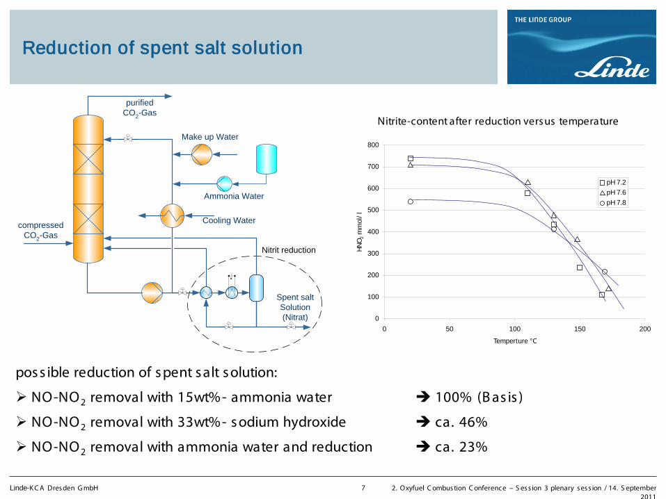
Reduction of spent salt solution
Cooling Water
Make up Water
Spent saltSolution(Nitrat)
Ammonia Water
compressedCO2-Gas
purifiedCO2-Gas
Nitrit reduction
pos s ible reduction of s pent s alt s olution:
NO-NO2 removal with 15wt%- ammonia water 100% (B as is )
NO-NO2 removal with 33wt%- s odium hydroxide ca. 46%
NO-NO2 removal with ammonia water and reduction ca. 23%
0
100
200
300
400
500
600
700
800
0 50 100 150 200
Temperture °C
HN
O2
mm
ol/l
pH 7.2
pH 7.6
pH 7.8
Nitrite-content after reduction versus temperature
Page 8
Linde-K C A Dres den G mbH 2. Oxyfuel C ombus tion C onference – S es s ion 3 plenary s es s ion / 14. S eptember 2011
8
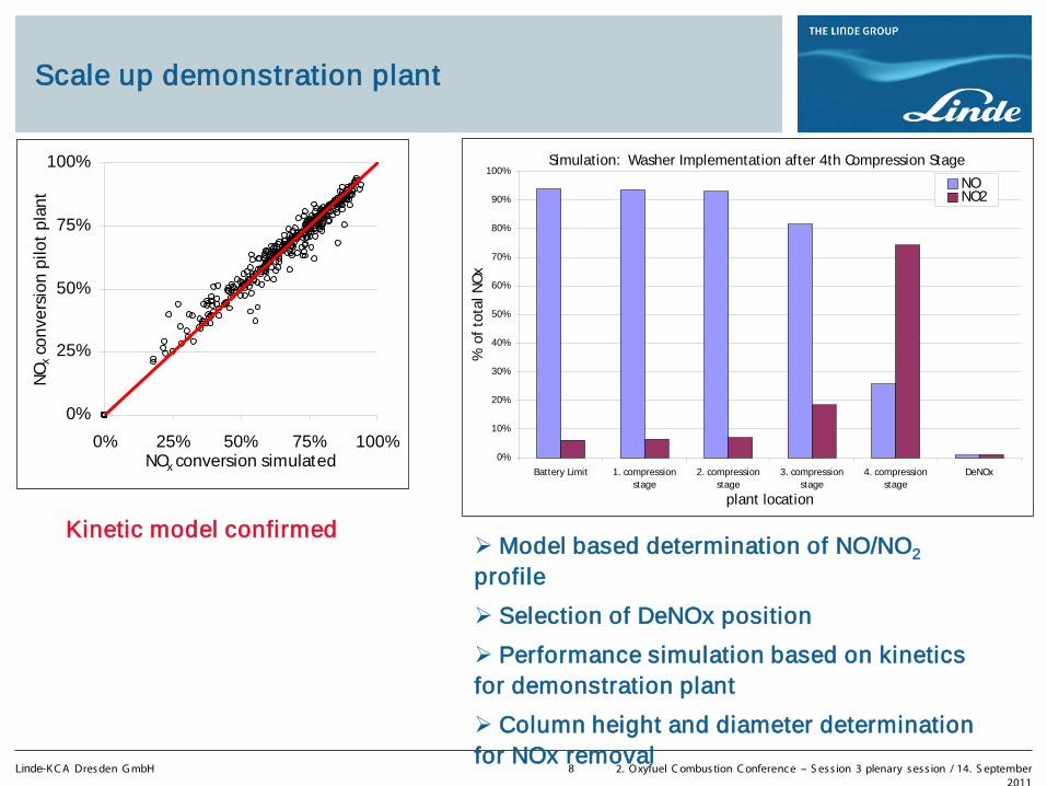
Scale up demonstration plant
Simulation: Washer Implementation after 4th Compression Stage
0%
10%
20%
30%
40%
50%
60%
70%
80%
90%
100%
Battery Limit 1. compressionstage
2. compressionstage
3. compressionstage
4. compressionstage
DeNOx
plant location
% o
f to
tal N
Ox
NONO2
0%
25%
50%
75%
100%
0% 25% 50% 75% 100%NOx conversion simulated
NO
x con
vers
ion
pilo
t pl
ant
Kinetic model confirmed
Model based determination of NO/NO2 profile
Selection of DeNOx position
Performance simulation based on kinetics for demonstration plant
Column height and diameter determination for NOx removal
Page 9
Linde-K C A Dres den G mbH 2. Oxyfuel C ombus tion C onference – S es s ion 3 plenary s es s ion / 14. S eptember 2011
9
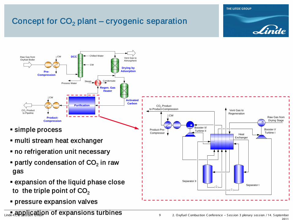
Concept for CO2 plant – cryogenic separation
Raw Gas fromOxyfuel Boiler
Pre-Compression
Product-Compression
Purification
CO2 Productto Pipeline
CW
CW
CW
Steam
Vent Gas toAtmosphere
Chilled Water
Condensate
DCC
Drying byAdsorption
Process Water
ActivatedCarbon
Regen. GasHeater
simple process
multi stream heat exchanger
no refrigeration unit necessary
partly condensation of CO2 in raw gas
expansion of the liquid phase close to the triple point of CO2
pressure expansion valves
application of expansions turbines
CW
Separator II
Separator I
HeatExchanger
Booster I/Turbine I
Booster II/Turbine IIProduct-Pre-
Compressor
CO2 Productto Product-Compression
Raw Gas fromDrying Stage
Vent Gas toRegeneration
Page 10
Linde-K C A Dres den G mbH 2. Oxyfuel C ombus tion C onference – S es s ion 3 plenary s es s ion / 14. S eptember 2011
10
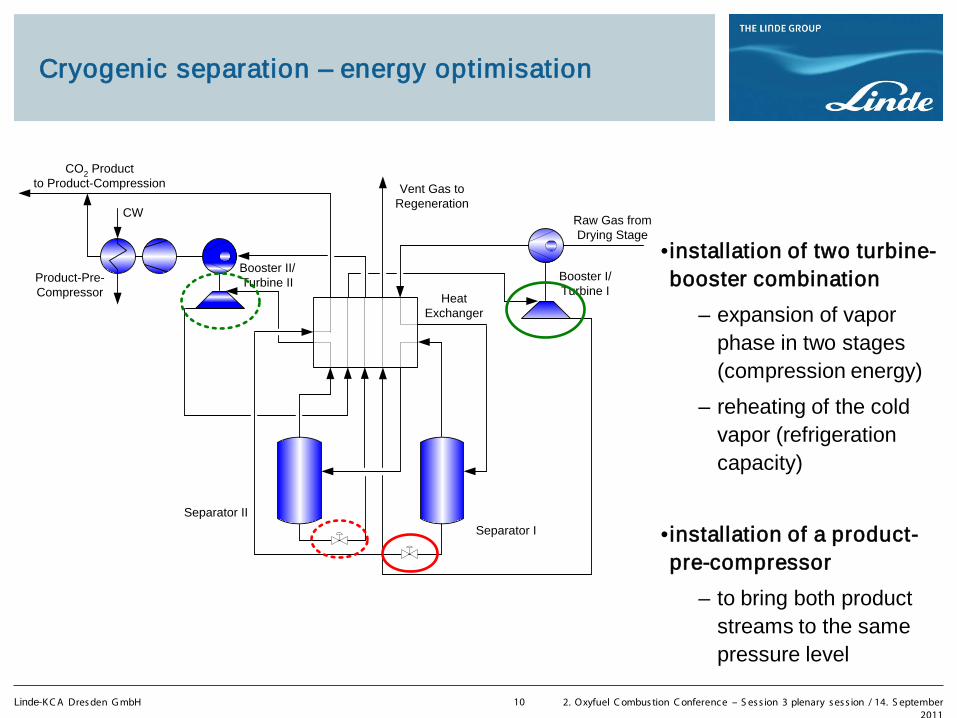
Cryogenic separation – energy optimisation
•installation of two turbine-booster combination
– expansion of vapor phase in two stages (compression energy)
– reheating of the cold vapor (refrigeration capacity)
•installation of a product-pre-compressor
– to bring both product streams to the same pressure level
CW
Separator II
Separator I
HeatExchanger
Booster I/Turbine I
Booster II/Turbine IIProduct-Pre-
Compressor
CO2 Productto Product-Compression
Raw Gas fromDrying Stage
Vent Gas toRegeneration
Page 11
Linde-K C A Dres den G mbH 2. Oxyfuel C ombus tion C onference – S es s ion 3 plenary s es s ion / 14. S eptember 2011
11
Application of valve and turbine expansion
Inlet
Inlet Outlet
Outlet
Expansion by Valve
Expansion by
Turbine
Page 12
Linde-K C A Dres den G mbH 2. Oxyfuel C ombus tion C onference – S es s ion 3 plenary s es s ion / 14. S eptember 2011
12
Possible Heat Integration
Heat integration will be optimized in the total oxyfuel process
•flue gas cooling
– plate heat exchanger for heating of BFW
•pre-compression
– compression with intermediate cooling temp. level of C O2 after compress ion 70 – 100°C
– cooling after every second compress ion stage temp. level of C O2 after compress ion 160 – 200°C heating of B F W
– but: higher electric energy consumption for the driver (lower efficiency)
•final CO2-product-compression
– without intermediate cooling
Page 13
Linde-K C A Dres den G mbH 2. Oxyfuel C ombus tion C onference – S es s ion 3 plenary s es s ion / 14. S eptember 2011
13
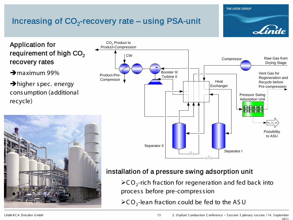
Increasing of CO2-recovery rate – using PSA-unit
CW
Separator II
Separator I
HeatExchanger
Compressor
Booster II/Turbine IIProduct-Pre-
Compressor
Pressure SwingAdsorption Unit
N2, O2, Ar
Possibilityto ASU
CO2 Product toProduct-Compression
Raw Gas fromDrying Stage
Vent Gas forRegeneration andRecycle beforePre-compression
Application for requirement of high CO2 recovery rates
maximum 99%
higher s pec. energy cons umption (additional recycle)
installation of a pressure swing adsorption unit
C O2-rich fraction for regeneration and fed back into proces s before pre-compres s ion
C O2-lean fraction could be fed to the AS U
Page 14
Linde-K C A Dres den G mbH 2. Oxyfuel C ombus tion C onference – S es s ion 3 plenary s es s ion / 14. S eptember 2011
14
Dynamic modeling of Oxyfuel power plant
Requirement of performance „ Transmission code 2000“
high flexibility of power stations; extreme changing of power load (4… 6%/ min)
especially with high renewables
day and night load
Dynamic simulation is key technology in the execution of Oxyfuel power plant
Goals of dynamic modeling:
ens ure robus t des ign of the plant
improve proces s efficiency
Load change evaluation
dis turbance analys es
C ontrol des ign and tuning
S tart-up and s hut-down analys es
better knowledge of trans ient plant behaviour in the clos e connection of all s eparated plants
Page 15
Linde-K C A Dres den G mbH 2. Oxyfuel C ombus tion C onference – S es s ion 3 plenary s es s ion / 14. S eptember 2011
15
Dynamic Modeling and Simulation Novel CCS processes pose challenges to plant engineering
n
CO2
ue Gas
G U e ts
Page 16
Linde-K C A Dres den G mbH 2. Oxyfuel C ombus tion C onference – S es s ion 3 plenary s es s ion / 14. S eptember 2011
16
A common intuitive HMI for dynamic process analysis is essential for collaboration among subject matter experts
HMI (human machine interface) - CO2 process Overview Screen
Page 17
Linde-K C A Dres den G mbH 2. Oxyfuel C ombus tion C onference – S es s ion 3 plenary s es s ion / 14. S eptember 2011
17
Reduced models for plant-wide simulation of oxyfuel plants – develop “ black box” models with minimal number of inputs and outputs
B oiler Model
G P U Model
AS U Model
Objective: S tudy overall performance of Oxyfuel proces s , by linking models from different tools , e.g. UniS im, OP T IS IM® (Linde-internal), …
Constraints: K now-how protection, reas onable computing times
P latform-independent model repres entation bas ed on black-box models (reduced models )
E xample: S ys tem Identification for G P U model
GPU model input:
F lue gas condition
GPU model outputs:
-P roduct and vent gas condition
-F eed header pressure
-C ompress ion power demand
Page 18
Thank you for your attention
Roland Ritter LINDE-KCA DRESDEN GmbH phone +49-351-250 3267 [email protected]