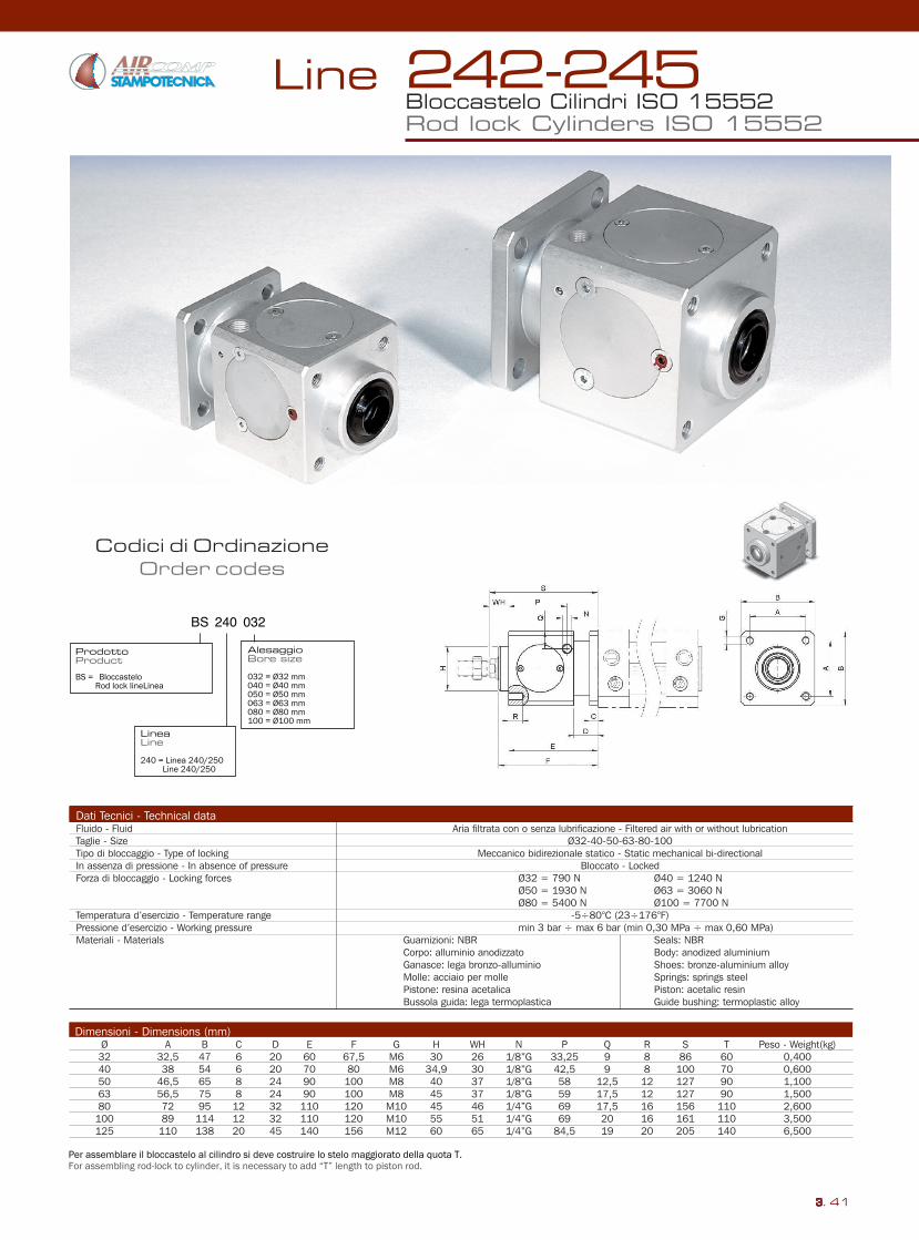
Codici di Ordinazione Order codes Line 3. 41 Dati Tecnici - Technical data Fluido - Fluid Aria filtrata con o senza lubrificazione - Filtered air with or without lubrication Taglie - Size Ø32-40-50-63-80-100 Tipo di bloccaggio - Type of locking Meccanico bidirezionale statico - Static mechanical bi-directional In assenza di pressione - In absence of pressure Bloccato - Locked Forza di bloccaggio - Locking forces Ø32 = 790 N Ø40 = 1240 N Ø50 = 1930 N Ø63 = 3060 N Ø80 = 5400 N Ø100 = 7700 N Temperatura d’esercizio - Temperature range -5÷80°C (23÷176°F) Pressione d’esercizio - Working pressure min 3 bar ÷ max 6 bar (min 0,30 MPa ÷ max 0,60 MPa) Materiali - Materials Guarnizioni: NBR Seals: NBR Corpo: alluminio anodizzato Body: anodized aluminium Ganasce: lega bronzo-alluminio Shoes: bronze-aluminium alloy Molle: acciaio per molle Springs: springs steel Pistone: resina acetalica Piston: acetalic resin Bussola guida: lega termoplastica Guide bushing: termoplastic alloy Dimensioni - Dimensions (mm) Ø A B C D E F G H WH N P Q R S T Peso - Weight(kg) 32 32,5 47 6 20 60 67,5 M6 30 26 1/8”G 33,25 9 8 86 60 0,400 40 38 54 6 20 70 80 M6 34,9 30 1/8”G 42,5 9 8 100 70 0,600 50 46,5 65 8 24 90 100 M8 40 37 1/8”G 58 12,5 12 127 90 1,100 63 56,5 75 8 24 90 100 M8 45 37 1/8”G 59 17,5 12 127 90 1,500 80 72 95 12 32 110 120 M10 45 46 1/4”G 69 17,5 16 156 110 2,600 100 89 114 12 32 110 120 M10 55 51 1/4”G 69 20 16 161 110 3,500 125 110 138 20 45 140 156 M12 60 65 1/4”G 84,5 19 20 205 140 6,500 Bloccastelo Cilindri ISO 15552 Rod lock Cylinders ISO 15552 242-245
Transcript
Codici di OrdinazioneOrder codes
Line
3. 41
Dati Tecnici - Technical dataFluido - Fluid Aria filtrata con o senza lubrificazione - Filtered air with or without lubricationTaglie - Size Ø32-40-50-63-80-100Tipo di bloccaggio - Type of locking Meccanico bidirezionale statico - Static mechanical bi-directionalIn assenza di pressione - In absence of pressure Bloccato - LockedForza di bloccaggio - Locking forces Ø32 = 790 N Ø40 = 1240 N Ø50 = 1930 N Ø63 = 3060 N Ø80 = 5400 N Ø100 = 7700 NTemperatura d’esercizio - Temperature range -5÷80°C (23÷176°F)Pressione d’esercizio - Working pressure min 3 bar ÷ max 6 bar (min 0,30 MPa ÷ max 0,60 MPa)Materiali - Materials Guarnizioni: NBR Seals: NBR Corpo: alluminio anodizzato Body: anodized aluminium Ganasce: lega bronzo-alluminio Shoes: bronze-aluminium alloy Molle: acciaio per molle Springs: springs steel Pistone: resina acetalica Piston: acetalic resin Bussola guida: lega termoplastica Guide bushing: termoplastic alloy
Bloccastelo Cilindri ISO 15552Rod lock Cylinders ISO 15552
242-245242-245 ø32÷200mm
Line
3. 42
Codici di OrdinazioneOrder codes
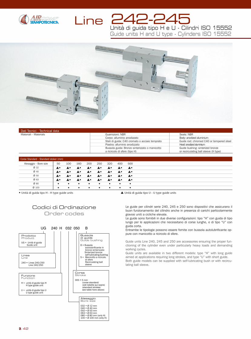
Dati Tecnici - Technical dataMateriali - Materials Guarnizioni: NBR Seals: NBR Corpo: alluminio anodizzato Body: anodized aluminium Steli di guida: C40 cromato o acciaio temprato Guide rod: chromed C40 or tempered steel Piastra: alluminio anodizzato Head: anodized aluminium Bussola guida: Bronzo sinterizzato o manicotto Guide bushing: sinterized bronze a ricircolo di sfere (tipo H) or recirculating ball sleeve (H type)
Le guide per cilindri serie 240, 245 e 250 sono dispositivi che assicurano il buon funzionamento del cilindro anche in presenza di carichi particolarmente gravosi uniti a cicliche elevate.Le guide sono fornibili in due diverse configurazioni: tipo “H” con guida di tipo lungo per le applicazioni che necessitano di corse lunghe, e di tipo “U” con guida corta. Entrambe le tipologie possono essere fornite con bussola autolubrificante op-pure con manicotto a ricircolo di sfere.
Guide units Line 240, 245 and 250 are accessories ensuring the proper fun-ctioning of the cylinder even under particularly heavy loads and demanding working cycles.Guide units are available in two different models: type “H” with long guide aimed at applications requiring long strokes, and type “U” with short guide.Both guide models can be supplied with self-lubricating bush or with recircu-lating ball sleeve.
Unità di guida tipo H e U - Cilindri ISO 15552Guide units H and U type - Cylinders ISO 15552
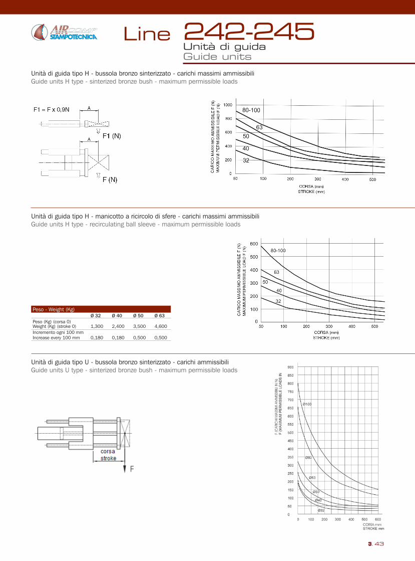
Unità di guida tipo H - bussola bronzo sinterizzato - carichi massimi ammissibiliGuide units H type - sinterized bronze bush - maximum permissible loads
Unità di guida tipo H - manicotto a ricircolo di sfere - carichi massimi ammissibiliGuide units H type - recirculating ball sleeve - maximum permissible loads
Unità di guida tipo U - bussola bronzo sinterizzato - carichi ammissibiliGuide units U type - sinterized bronze bush - maximum permissible loads


![mlit.go.jp · 2019. 2. 1. · [235] [235) 123 [24.2] [240] [240] [24.3] [242 [242 [242] [242) [245 43] [242 (242 [242] [24.2] [ú.2] [242] [242 [240] [242] 27 087 087 [24.6] [24.6]](https://static.documents.pub/doc/80x56/613019b41ecc51586943e0fb/mlitgojp-2019-2-1-235-235-123-242-240-240-243-242-242-242.jpg)


