1/10 Line Lock Package, Camaro 2010-2011 PACKING LIST Before installation, use this check list to make sure all necessary parts have been included. WARNING: SLP Recommends wearing safety glasses for the complete installation. WARNING: SLP Recommends allowing the vehicle to cool (not running) for five hours before beginning installation. WARNING: Too avoid the chance of electrical shock or damage to your vehicle’s electrical system, disconnect both the negative and positive batter leads (in that order) at the battery. INSTALLATION INSTRUCTIONS – #25005 1. First drain the brake fluid from the master cylinder reservoir by either sucking the fluid out from the top or removing the rear brake line and letting the fluid drip into a cup. If the reservoir is not drained properly, brake fluid will drip onto you and your vehicle. 2. Next disconnect the negative battery terminal PART #25005 ITEM QTY CHECK PART NUMBER DESCRIPTION 1. 1 020402305 Harness, Wire, Solenoid to Switch 2. 1 020402306 Harness, Wire, Power to Switch 3. 1 020402307 Harness, Wire, Solenoid to Ground 4. 1 260093100 Line,Master Cylinder to Solenoid Brake, Camaro, 5th Gen 5. 1 260093101 Line, ABS to Solenoid Brake,Camaro, 5th Gen 6. 1 020758100 Solenoid 7. 2 020706250 Self Drilling Hex Head Screws 8. 1 950846785 Union, 12 mm X 1.5, SAE 45 Inverted Flare 9. 2 950330787 Fitting, 12 mm Inverted Female to 1/8" NPT Male 10. 1 050501863 SLP Logo Adhesive Label w/o dome resin 11. 1 020895524 Switch 12. 1 Instructions
Transcript
1/10
Line Lock Package, Camaro 2010-2011 PACKING LIST Before installation, use this check list to make sure all necessary parts have been included.
WARNING: SLP Recommends wearing safety glasses for the complete installation.
WARNING: SLP Recommends allowing the vehicle to cool (not running) for five hours before beginning
installation.
WARNING: Too avoid the chance of electrical shock or damage to your vehicle’s electrical system,
disconnect both the negative and positive batter leads (in that order) at the battery.
INSTALLATION INSTRUCTIONS – #25005
1. First drain the brake fluid from the master cylinder reservoir by either sucking the
fluid out from the top or removing the rear brake line and letting the fluid drip into a
cup. If the reservoir is not drained properly, brake fluid will drip onto you and your
vehicle.
2. Next disconnect the negative battery terminal
PART #25005
ITEM QTY CHECK PART NUMBER DESCRIPTION
1. 1 020402305 Harness, Wire, Solenoid to Switch
2. 1 020402306 Harness, Wire, Power to Switch
3. 1 020402307 Harness, Wire, Solenoid to Ground
4. 1 260093100
Line,Master Cylinder to Solenoid Brake, Camaro, 5th Gen
5. 1 260093101 Line, ABS to Solenoid Brake,Camaro, 5th Gen
6. 1 020758100 Solenoid
7. 2 020706250 Self Drilling Hex Head Screws
8. 1 950846785 Union, 12 mm X 1.5, SAE 45 Inverted Flare
9. 2 950330787 Fitting, 12 mm Inverted Female to 1/8" NPT Male
10. 1 050501863 SLP Logo Adhesive Label w/o dome resin
11. 1 020895524 Switch
12. 1 Instructions
2/10
3. Next, remove the brake line that runs to the rear port of the master cylinder. Once
removed push the line so that it stays “under” the master cylinder. See Photo 1 below
for location of line in master cylinder.
Photo 1: Location of Front Brake Line on Master Cylinder
4. Next, pre-assemble the included brake line that runs from the solenoid to factory tube
nut on the brake line removed in step 3 above. Assemble as shown in the photo
below with the included female/female coupler. DO NOT USE any thread sealer as
this coupler will seal on the flare at the end of the line. Tighten the coupler to this
line now as shown in photo 2 below.
Photo 2: Solenoid to Stock Brake line assembly (out of car)
3/10
5. Next install the line assembled in step 4 above onto the stock line/tube nut removed in
step 3 above. See photo 3 below.
Photo 3
4/10
6. Next, install the remaining brake line included in the kit onto the rear of the master
cylinder as shown in the photo below. The end of the line that has a 90 degree bend
goes into the master cylinder.
Photo 4
7. Next, install the two 1/8” NPT to 12mm Flare fitting onto the solenoid. USE
TEFLON TAPE ONLY ON THE 1/8” NPT THREAD INTO THE SOLENOID.
Next insert the solenoid between the two lines loosely (NOTE: Make sure the side
marked MC is facing the Master Cylinder.) installed in step 6. Position the solenoid
so that both lines are relaxed and mark through the mounting holes to the fender with
a sharpie where you will be drilling for the mounting screws. See photo 5 below.
Photo 5
5/10
8. Remove the solenoid and drill a pilot hole on each mark made in step 7.
9. Mount the solenoid to the fender using the supplied hardware making sure to first
plug the ground wire onto the solenoid then behind one of the included solenoid
mounting screws. See photo 6 below.
Photo 6
6/10
10. Tighten all of the tube nuts.
11. Fill the reservoir with brake fluid.
12. BLEED THE BRAKE SYSTEM.
13. Next, install the remaining 2 supplied wire harnesses.
14. Connect the “power to switch harness” (the only harness containing a fuse) to the fuse
box as shown below (circuit 15). Removing the 5 amp fuse from the fuse box (circuit
15) connecting the fuse back into the open space in the harness then plugging the
harness assembly back into the fuse box. (circuit 15) Route the wire out of the fuse
box as shown in photo 8 below.
Photo 7
7/10
Photo 8
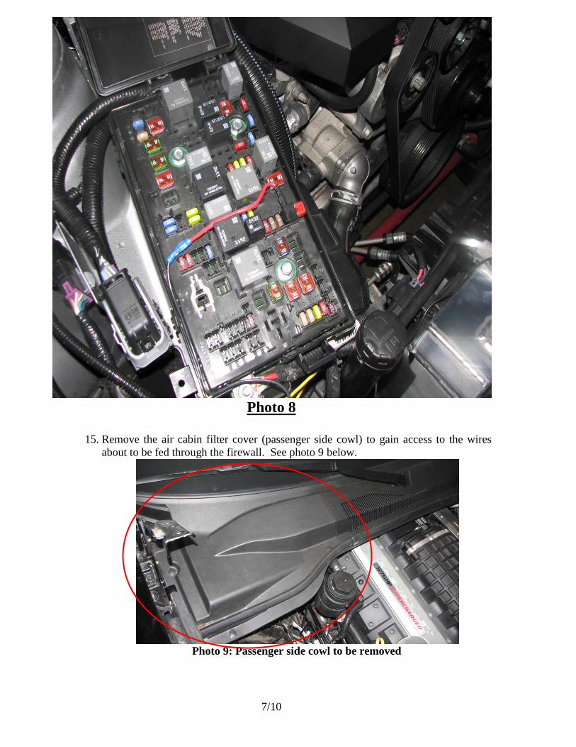
15. Remove the air cabin filter cover (passenger side cowl) to gain access to the wires
about to be fed through the firewall. See photo 9 below.
Photo 9: Passenger side cowl to be removed
8/10
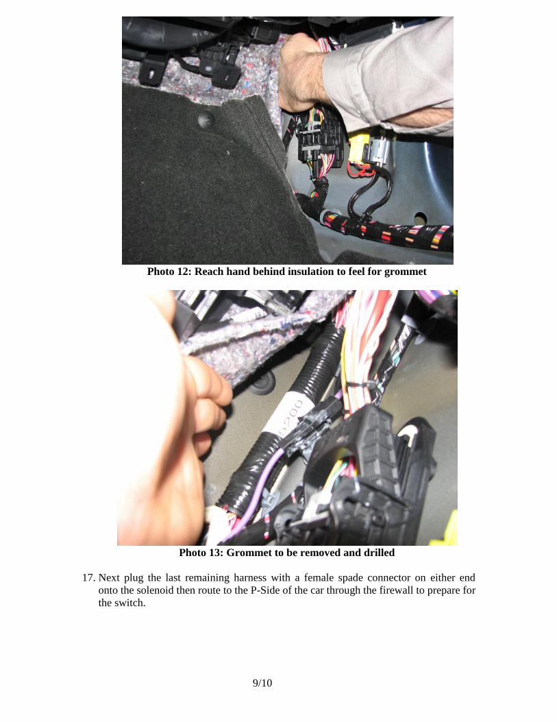
16. Route the wire through the firewall from the inside of the car to the outside on the P-
side. There is a grommet that goes through the firewall that the wire can go though.
Remove the grommet, poke a hole in the center, run the wire though it, and re-install
the grommet into the firewall. The grommet is difficult to see, but feel around the
wire harness near the kick panel for the grommet. You will have to remove the
plastic passenger side door sill and kick panel to get to this grommet, as well as pull
back the insulation. Feed 6 inches of the wire through the grommet and it will appear
where you removed the cowl. See photos 10, 11, 12, and 13 below.
Photo 10: P-side plastic door sill to remove
Photo 11: P-side kick panel removal
9/10
Photo 12: Reach hand behind insulation to feel for grommet
Photo 13: Grommet to be removed and drilled
17. Next plug the last remaining harness with a female spade connector on either end
onto the solenoid then route to the P-Side of the car through the firewall to prepare for
the switch.
10/10
18. Next mount the switch and plug the power and solenoid harnesses into the switch. A
suggested switch location is shown below. To make the mounting hole use a ½” drill
bit.
Photo 14: Suggested location
Photo 15: Suggested location with switch installed
19. Re-install all panels and clips. Tuck away/wire tie any loose wires.