49
Line Protection Roy Moxley – Siemens USA siemens.com/digitalgrid Unrestricted © Siemens AG 2017

Line ProtectionRoy Moxley – Siemens USA
siemens.com/digitalgridUnrestricted © Siemens AG 2017

What is a Railroad’s Biggest Asset ?
• Rolling Stock
• Share-holders
• Relationships
• Shipping Contracts
• Employees (Engineers)
• Tracks and Right of Way

What is a Railroad’s Biggest Asset ?
• Rolling Stock
• Share-holders
• Relationships
• Shipping Contracts
• Employees (Engineers)
• Tracks and Right of Way

Transmission Lines are the Power System’s Largest Asset

Exposed to Weather
Self-Sustaining Arc
Clear Quickly to Avoid Permanent Damage
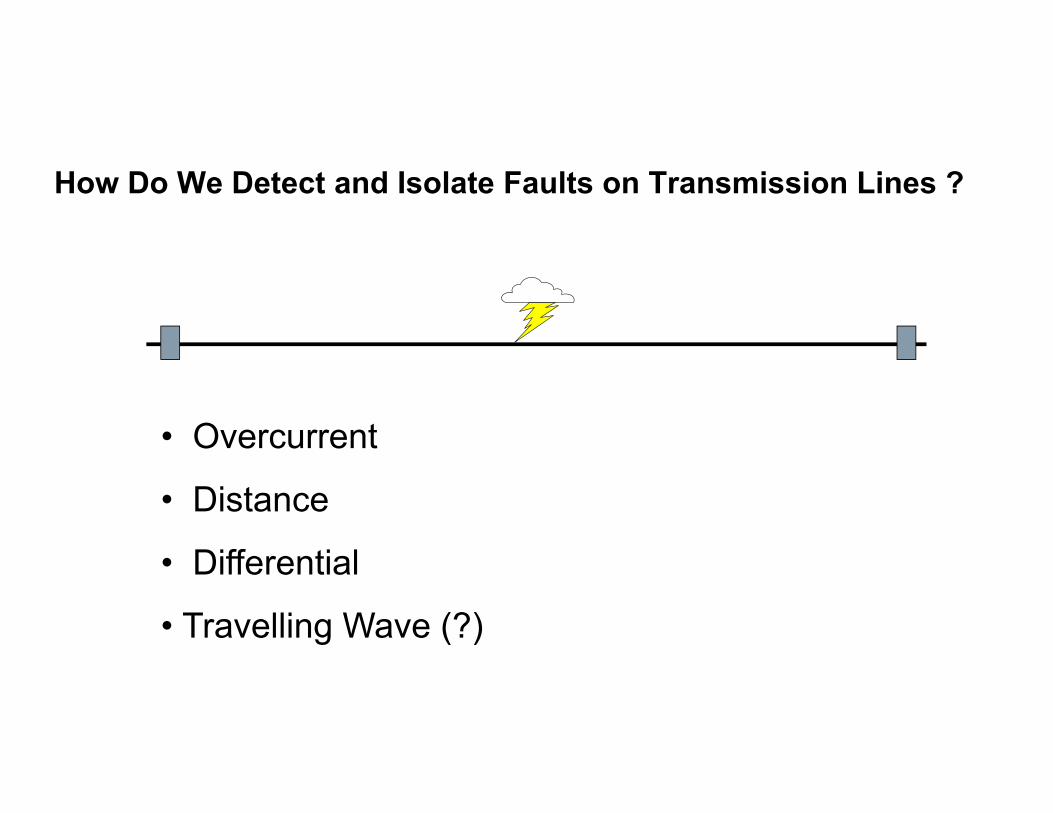
How Do We Detect and Isolate Faults on Transmission Lines ?
• Overcurrent
• Distance
• Differential
• Travelling Wave (?)

Overcurrent I>PU
1000 A
Advantages:•Simple•Reliable•Easy to Set
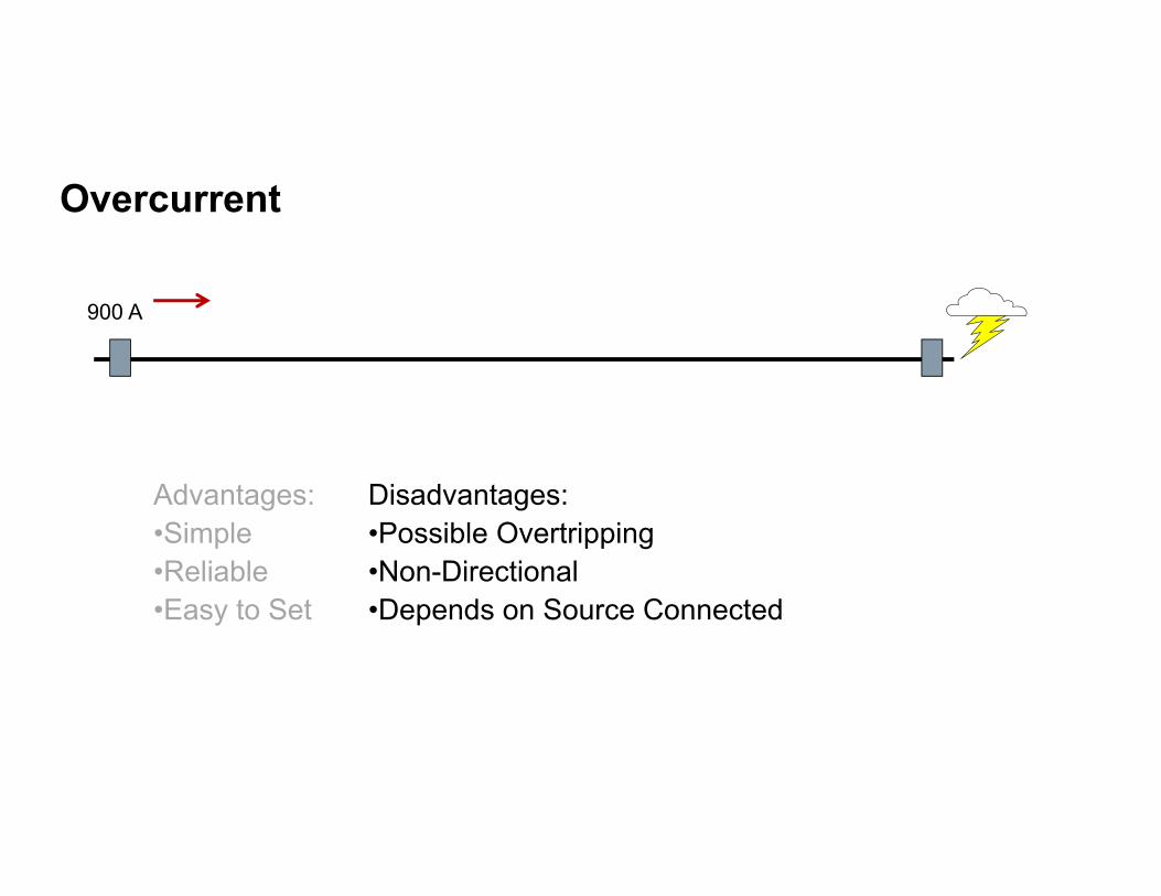
Overcurrent
900 A
Advantages:•Simple•Reliable•Easy to Set
Disadvantages:•Possible Overtripping•Non-Directional•Depends on Source Connected
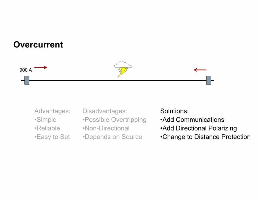
Overcurrent
900 A
Advantages:•Simple•Reliable•Easy to Set
Disadvantages:•Possible Overtripping•Non-Directional•Depends on Source
Solutions:•Add Communications•Add Directional Polarizing•Change to Distance Protection
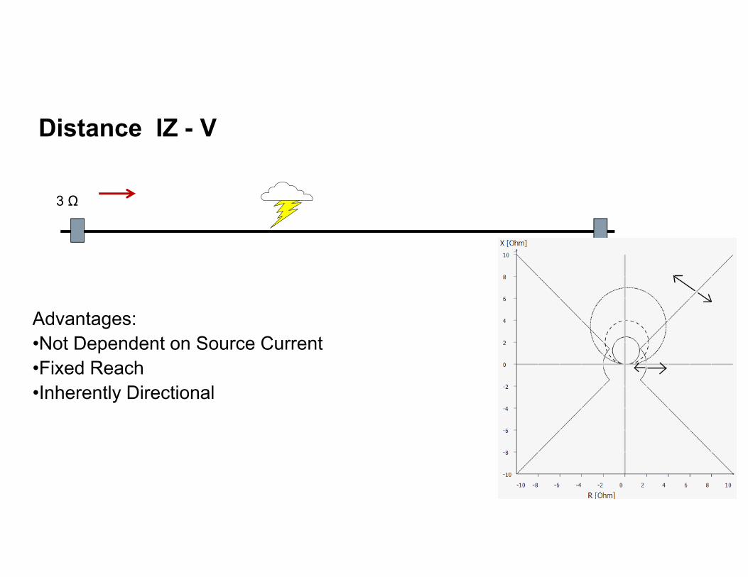
Distance IZ - V
3 Ω
Advantages:•Not Dependent on Source Current•Fixed Reach•Inherently Directional
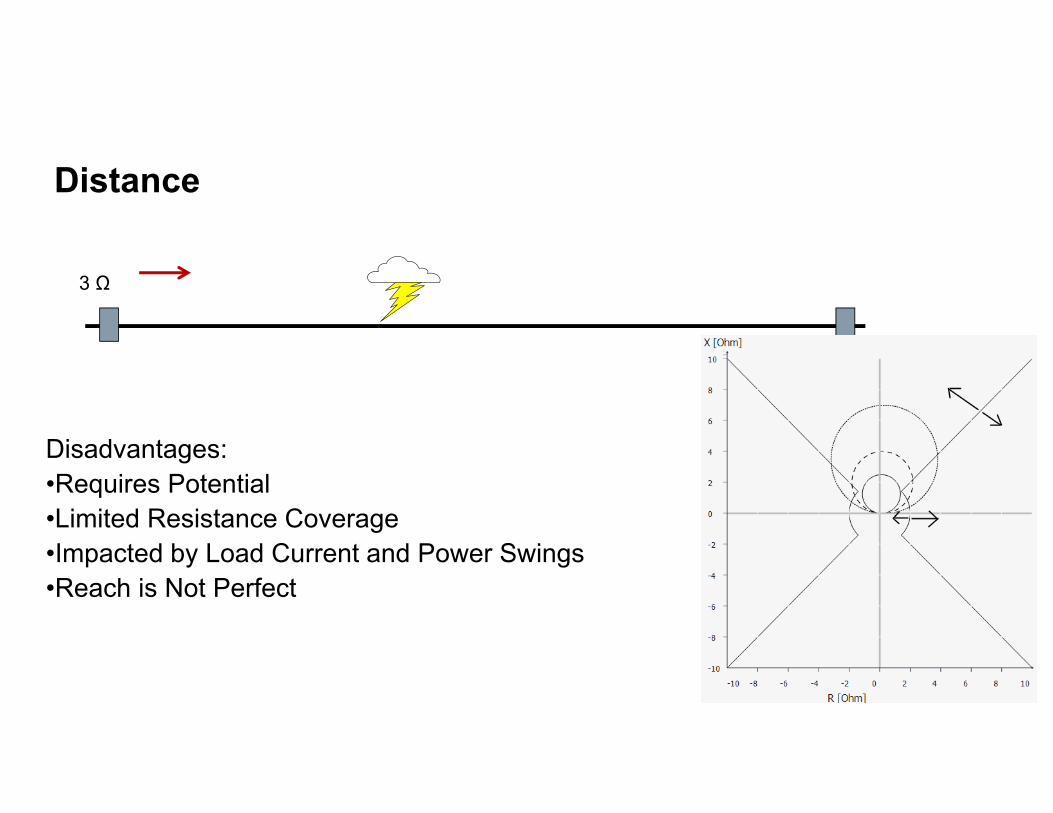
Distance
3 Ω
Disadvantages:•Requires Potential•Limited Resistance Coverage•Impacted by Load Current and Power Swings•Reach is Not Perfect
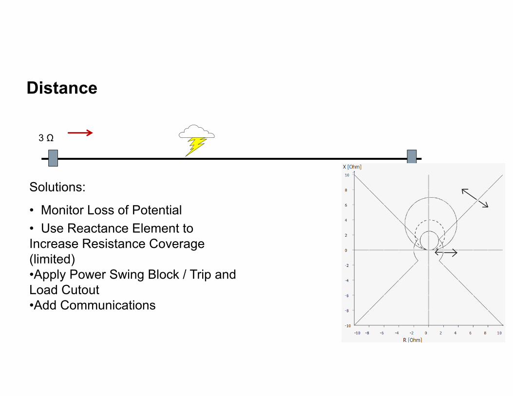
Distance
3 Ω
Solutions:
• Monitor Loss of Potential• Use Reactance Element to Increase Resistance Coverage (limited)•Apply Power Swing Block / Trip and Load Cutout•Add Communications
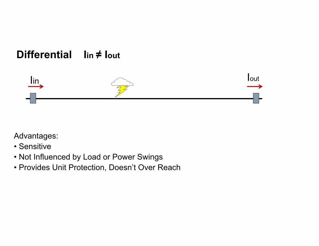
Differential Iin ≠ Iout
Advantages:• Sensitive• Not Influenced by Load or Power Swings• Provides Unit Protection, Doesn’t Over Reach
Iin Iout
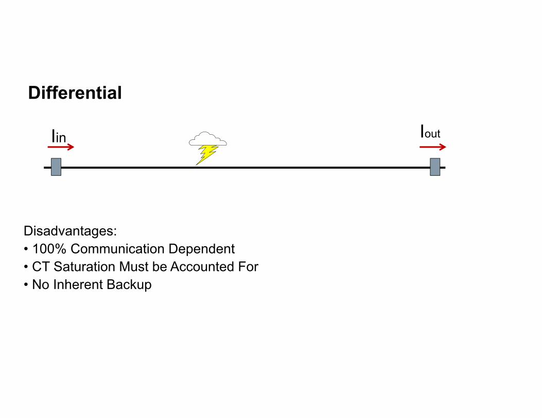
Differential
Disadvantages:• 100% Communication Dependent• CT Saturation Must be Accounted For• No Inherent Backup
Iin Iout

Differential
Solutions:• Monitor Communications• Detect and Account for CT Saturation• Provide Backup With No Communications or on Different Channel
Iin Iout

Traveling Wave
Advantages:• Sensitive• Minimal Settings• Fast• Precise Fault Location
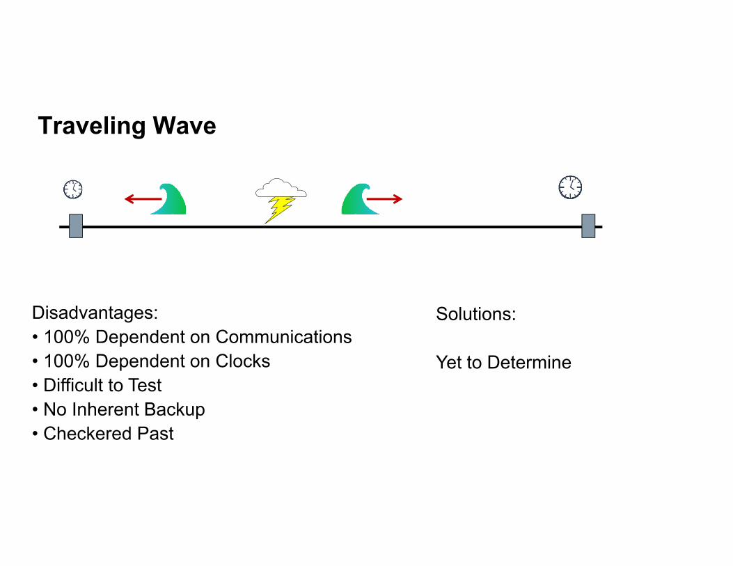
Traveling Wave
Disadvantages:• 100% Dependent on Communications• 100% Dependent on Clocks• Difficult to Test• No Inherent Backup• Checkered Past
Solutions:
Yet to Determine

Every System Has Strengths and Weaknesses

Communications is King
Overcomes Weakness
Enhances Strengths
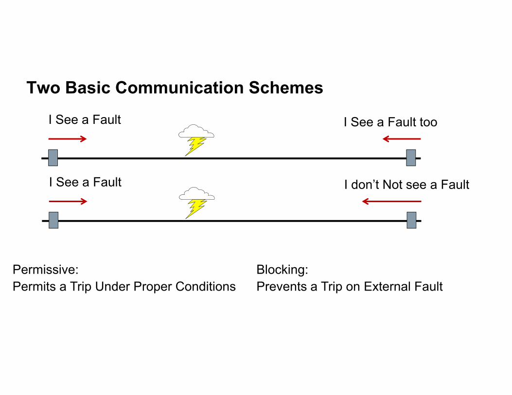
Two Basic Communication Schemes
Permissive:Permits a Trip Under Proper Conditions
I See a Fault I See a Fault too
I See a Fault I don’t Not see a Fault
Blocking:Prevents a Trip on External Fault
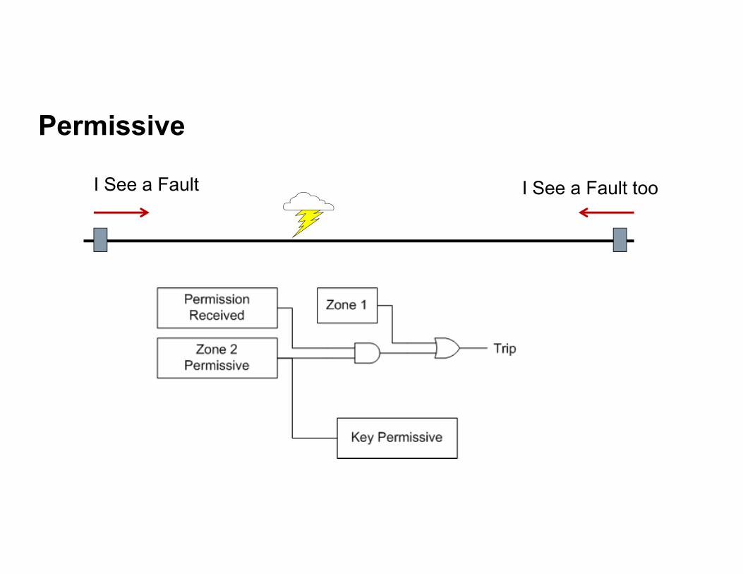
Permissive
I See a Fault I See a Fault too
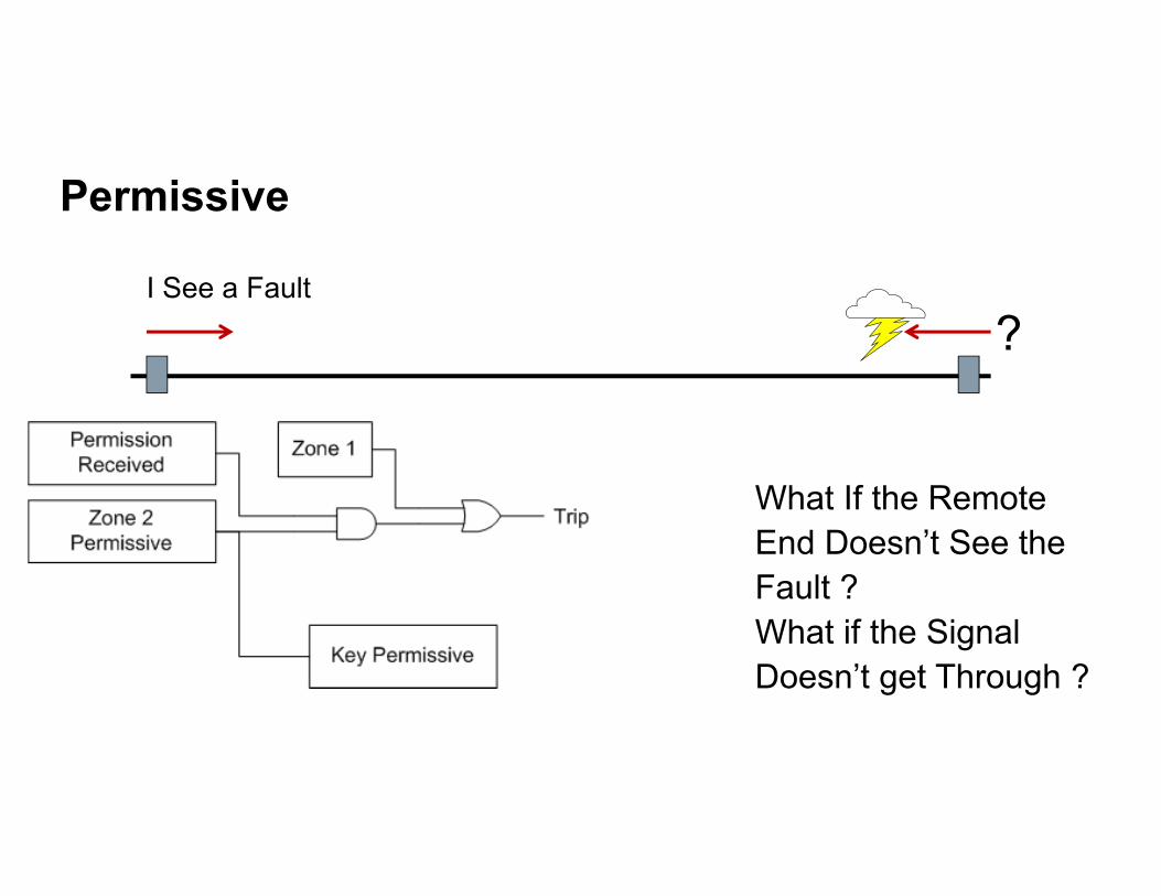
Permissive
I See a Fault
?
What If the Remote End Doesn’t See the Fault ?What if the Signal Doesn’t get Through ?

BlockingI See a Fault
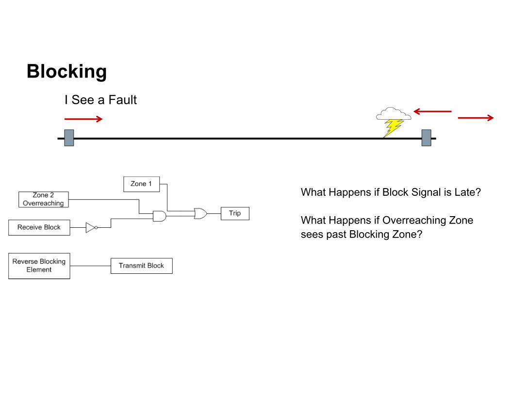
BlockingI See a Fault
What Happens if Block Signal is Late?
What Happens if Overreaching Zone sees past Blocking Zone?

Hybrid SchemeI See a Fault
Weak InfeedI See No Fault
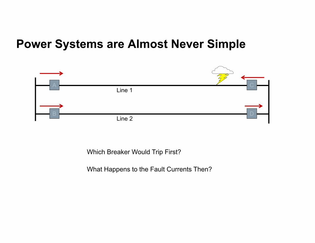
Power Systems are Almost Never Simple
CA
DB
Line 1
Line 2
Which Breaker Would Trip First?
What Happens to the Fault Currents Then?
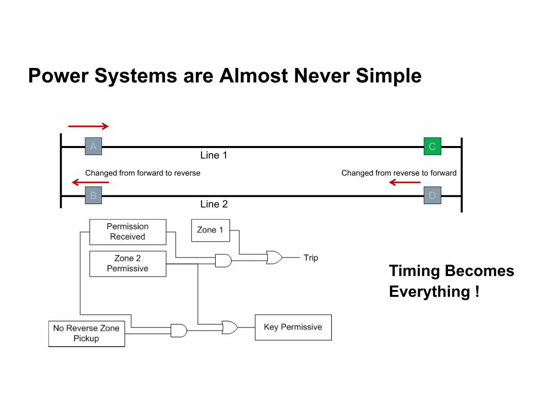
Power Systems are Almost Never Simple
CA
DB
Line 1
Line 2
Changed from forward to reverse Changed from reverse to forward
Timing Becomes Everything !

Three (or More) Terminals Save Money
BA
C
Blocking or Permissive ?

Sensitivity
On Short Lines Ground Resistance Can Be Higher than Line Impedence
But What Can Happen if we Just Increase Resistive Reach?
18 Ω
3 Ω

Load Flow and Sensitivity
Load Trajectory
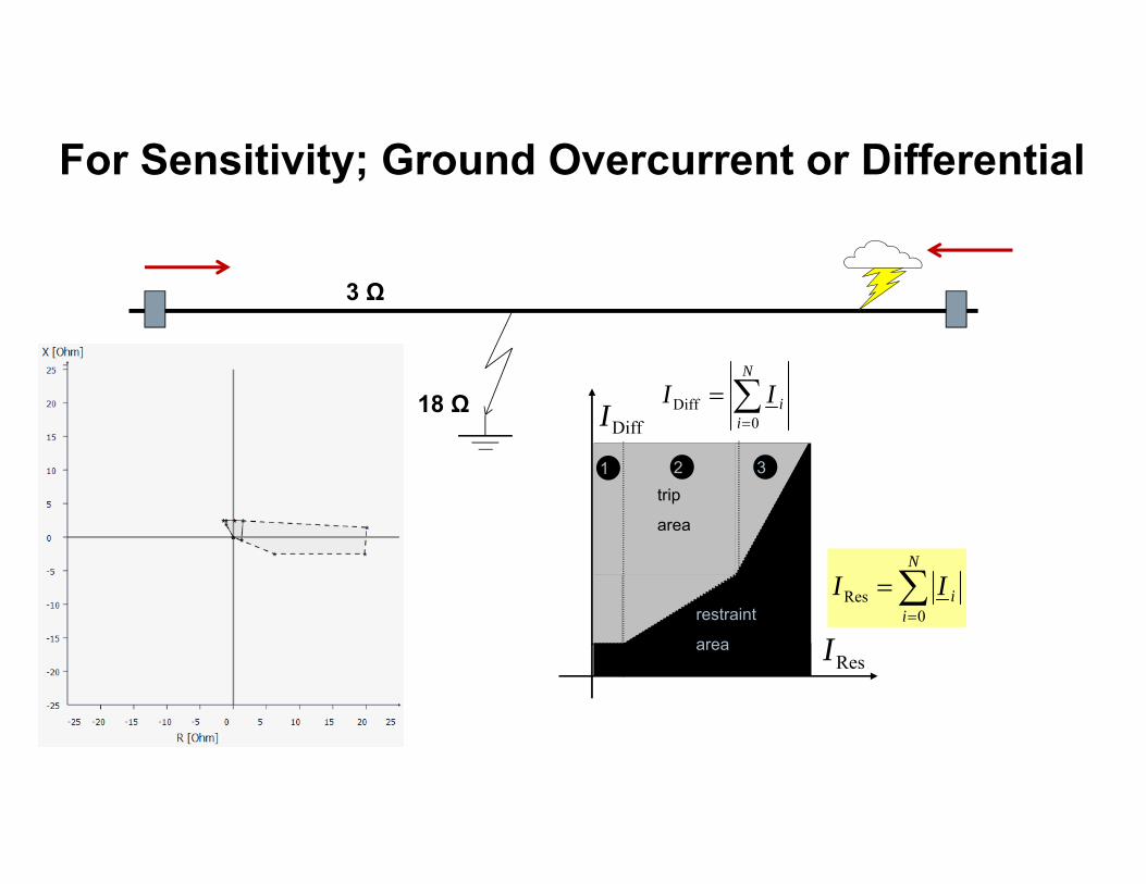
For Sensitivity; Ground Overcurrent or Differential
18 Ω
3 Ω
DiffI
ResI
trip
area
restraint
area
1 2 3
N
iiII
0Diff
N
iiII
0Res

Differential Relays Have to Accommodate CT saturation
relay measures a distorted current signal (red curve)
relay calculates the fundamental frequency component (blue curve)
deviation between both curves (green area) is a criteria for signal distortion
relay determines restrained current depending this signal deviation

Restraining on Errors
AI
AI
BI
BI IRe
IImeach I is the summation of:Ii = ICT-Err.+ ISignal-Err.+ISync-Err.
DiffI
BI
AI
AI BII
Res_minRes III
min_Re sI Trip if differential current exceeds sum of measurement errors added by safety margin IRes_min
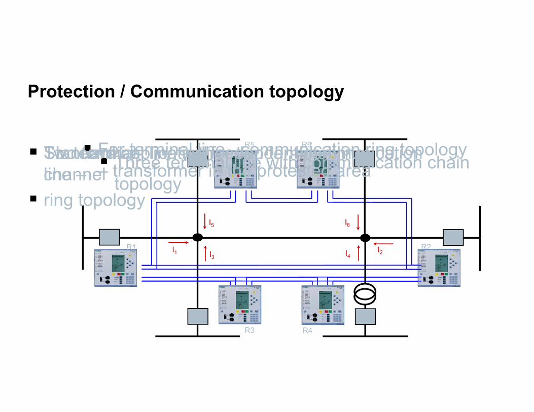
Protection / Communication topology
I2I1 R2R1
R5
I5
R6
I6
R3
I3
Standard application for two terminal line: Two terminal line with redundant communication channel Three terminal line with communication chain
topology
R4
I4
For terminal line - communication ring topology – transformer in the protected area
Six terminal line – ring topology

Special Conditions - Transformers in Zone
Wind Farm
Inrush ? 2nd Harmonic Restraint
Ratio and Angle Correction for differential
Reach for Distance Relay
Will the relay see through the transformer for ground faults?

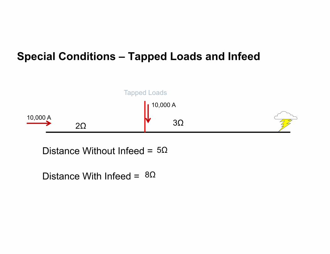
Special Conditions – Tapped Loads and Infeed
Tapped Loads
2Ω 3Ω
Distance Without Infeed =
Distance With Infeed =
10,000 A
10,000 A
Special Conditions – Tapped Loads and Infeed
Tapped Loads
2Ω 3Ω
Distance Without Infeed =
Distance With Infeed =
10,000 A
10,000 A
5Ω
8Ω

Special Conditions Combined
Wind Farm
Tapped Loads
Major Industrials
Photo VoltaicDifferential – Multi-terminalDistance – Blocking SchemeDistance (no-Comms) – Sequential Tripping

Relay 1
Relay 6
Relay 2
Relay 5
Relay 3
Relay 4
Information sent to all Relays by Transmitting “Partial Summation”
Addressed Data Sent Until All Terminals Have All the Data
I1
I5
I4
I3
I2
I6
I2 +I3+I4+I5+I6
I2 +I1
Hot Standby
I6
I5 +I6
I4 +I5+I6
I3+I4 +I5+I6
I1I3+I2 +I1
I4+I3+I2 +I1
I5+I4+I3+I2 +I1
Relay 1
Relay 6
Relay 2
Relay 5
Relay 3
Relay 4
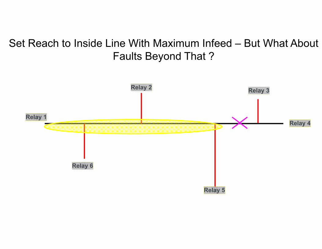
Set Reach to Inside Line With Maximum Infeed – But What About Faults Beyond That ?
Relay 1
Relay 6
Relay 2
Relay 5
Relay 3
Relay 4
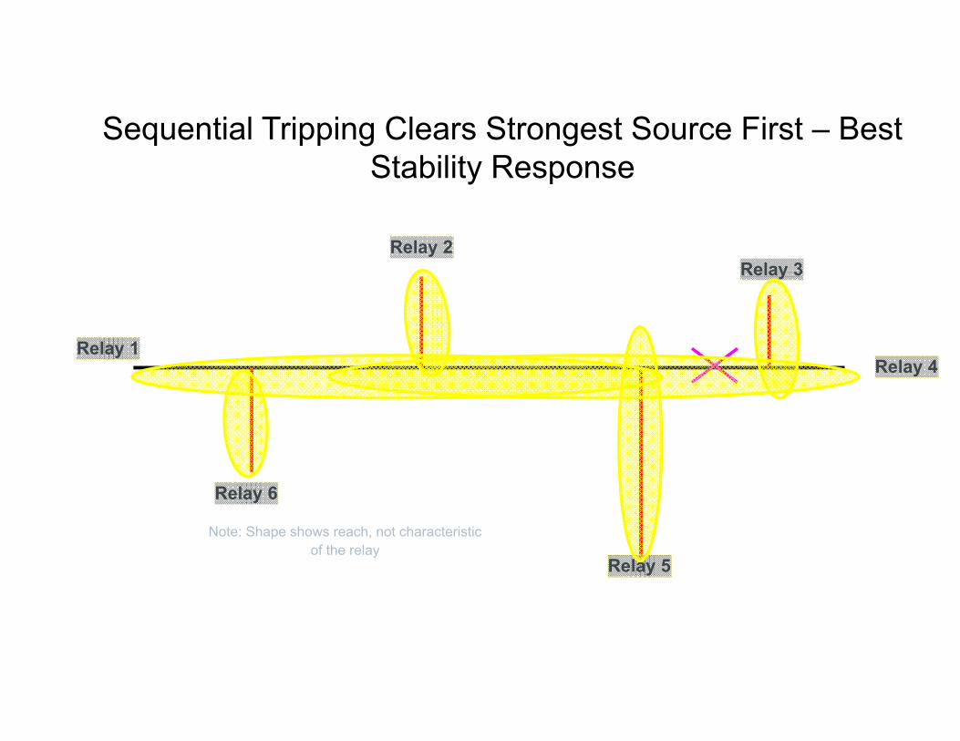
Sequential Tripping Clears Strongest Source First – Best Stability Response
Note: Shape shows reach, not characteristic of the relay

Phu My
Industrial
Area
New Plant 720 MW total from Three Units
Real-World Application

Things Don’t Always End Up How You Expect !!
Who Me ?

Initial Plans Were Pretty Standard500 kV Station

GT 1 GT 2 ST 3
Everything Wasn’t Ready On Time –Changes Connections
220 kV Station
450 MVA
500 / 220 kV
450 MVA
500 / 220 kV
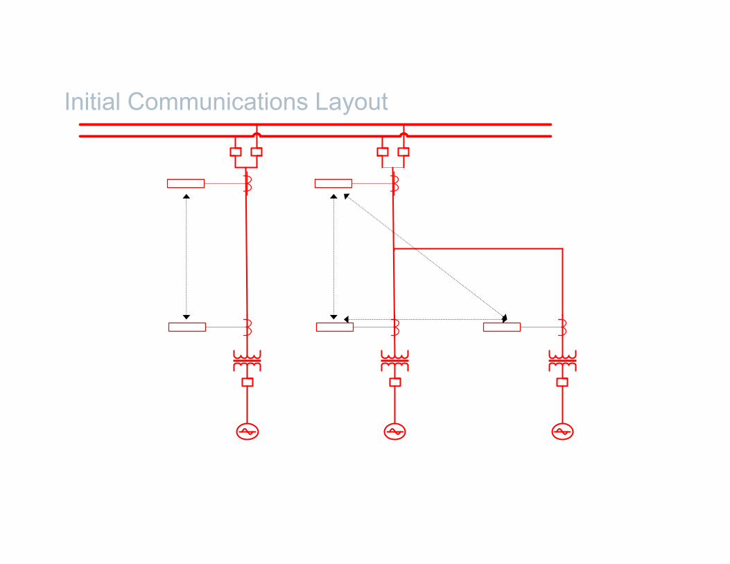
Initial Communications Layout
GT 1 GT 2 ST 3
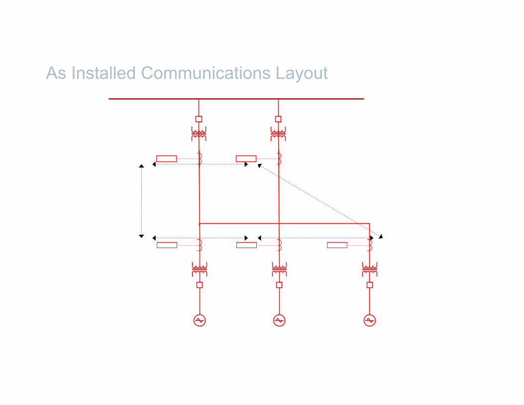
As Installed Communications Layout

It’s OK

Contact
Roy MoxleySiemens Power Systems Protection Consultant
Phone: 509-288-0847
E-mail:[email protected]


