351 SPOJ 0,5 0,75 1 1,5 2,5 4 6 10 16 6 9 13,5 17,5 24 32 41 57 76 25 35 50 70 95 120 150 185 240 101 125 150 192 232 269 309 353 415 M2,5 0,4 0,7 - - M 3 0,5 1,0 - - M 3,5 0,8 1,4 - - M 4 1,2 2,0 1,2 2,0 M 5 2,0 4,0 2,0 4,0 M 6 2,5 5,0 3,0 6,0 M 8 3,5 - 6,0 12,0 M 10 4,0 - 10,0 20,0 DATA Terminal’s elements Insulation part The material of the insulating body of the terminals type VS PA is PA 6.6 polyamide (self–exstinguishable - colour of ebony acc. to RAL 1014) which is made of polyamide resin and has higher temperature resistance, it is thermal stabi- lized and is resistant to aging. Polyamide 6.6 has good geometrical stability and excellent mechanical resistance. The material satisfies regulation according to IEC 695-2-1. It is suitable for use in temperature range from -40º C to +100º C according to IEC 216 rules. In the mentioned range the material remains unchanged. It is resistant to oils, greases, salts, several alkaline solutions ant to low percentage of acid concentration. It is resistant to micro-organisms, bacteria, fungi, enzymes and termites. The design of the insulation body of the terminal consider the regulations of air and creepage distances of nominal voltage according IEC 947-1. Terminal body The terminal body of 2,5 mm 2 connecting elements are made from brass, others are made from steel. The body is equipped with a hole with thread for obtaining screw pressure. In the final phase of the production the bodies of brass are treated by coating with Ni and other are treated by coating with 12 microns of zinc and with blue pasivation. In this way galvanically and corrosion protection is obtained. The terminal body has excellent mechanical characteristics and they are not subject to mechanical deformation in ordinary use, which are prescribed with IEC 947-1 regulations. Terminal bodies are equipped with body nose (except terminal body VS 2.5 PA). So, it is avoided to insert cable under body if the terminal body is closed or half closed. Conducting bar The conducting bar is made of copper and is galvanically protected with 6 microns tin in surface. The coating provides ideal conducting characteristics and better surface contact, at the same time the corrosion effect is reduced. Conducting bushes They are made of brass containing a high percentage of cooper and they are protected against atmospheric corroding agents, chemical corrosion and marine corrosion by galvanic treatment. Screws The screws are made of steel, treated to have a hard coating and they obtain a high tightening torque. Screws are equipped with metric threads according ISO and are galvanically protected against corrosion with 8 microns zinc. Screws are designed to sustain mechanical tightening torque according to IEC 947-1. Current carrying capacity of conduct The table below lists the test currents of the individual conductor cross sections as specified in the European standard IEC 947-7-1. Terminal blocks that are tested with this load must maintain the tolerance limits specified in the standard (e.g. maximum temperature rise). Tightening screw torque of terminal blocks IEC 947-7-1 specifies mechanical tests for judging the quality of the connection elements. According to these tests conductors should be connected by tightening the terminal block screws with a certain torque. The value of the torque depends on the dimensions of the terminal block screw and is shown in the table below. The relatively low torque allows safe connections. Line-up terminal Test currents in acc. with IEC 947-7-1 table V Rated cross section [mm 2 ] Test current [A] Rated cross section [mm 2 ] Test current [A] Extract from IEC 947-1 table IV Thread Head screw with slot Head screw without slot - hexa- gon nut Tightening torque [Nm] Maximal tightening torque [Nm] Steel screw Steel screw
Terminal’s elementsInsulation partThe material of the insulating body of the terminals type VS PA is PA 6.6 polyamide (self–exstinguishable - colour of ebony acc. to RAL 1014) which is made of polyamide resin and has higher temperature resistance, it is thermal stabi-lized and is resistant to aging. Polyamide 6.6 has good geometrical stability and excellent mechanical resistance. The material satisfies regulation according to IEC 695-2-1. It is suitable for use in temperature range from -40º C to +100º C according to IEC 216 rules. In the mentioned range the material remains unchanged. It is resistant to oils, greases, salts, several alkaline solutions ant to low percentage of acid concentration. It is resistant to micro-organisms, bacteria, fungi, enzymes and termites. The design of the insulation body of the terminal consider the regulations of air and creepage distances of nominal voltage according IEC 947-1.Terminal bodyThe terminal body of 2,5 mm2 connecting elements are made from brass, others are made from steel. The body is equipped with a hole with thread for obtaining screw pressure. In the final phase of the production the bodies of brass are treated by coating with Ni and other are treated by coating with 12 microns of zinc and with blue pasivation. In this way galvanically and corrosion protection is obtained. The terminal body has excellent mechanical characteristics and they are not subject to mechanical deformation in ordinary use, which are prescribed with IEC 947-1 regulations. Terminal bodies are equipped with body nose (except terminal body VS 2.5 PA). So, it is avoided to insert cable under body if the terminal body is closed or half closed.Conducting barThe conducting bar is made of copper and is galvanically protected with 6 microns tin in surface. The coating provides ideal conducting characteristics and better surface contact, at the same time the corrosion effect is reduced.Conducting bushesThey are made of brass containing a high percentage of cooper and they are protected against atmospheric corroding agents, chemical corrosion and marine corrosion by galvanic treatment.ScrewsThe screws are made of steel, treated to have a hard coating and they obtain a high tightening torque. Screws are equipped with metric threads according ISO and are galvanically protected against corrosion with 8 microns zinc. Screws are designed to sustain mechanical tightening torque according to IEC 947-1.
Current carrying capacity of conductThe table below lists the test currents of the individual conductor cross sections as specified in the European standard IEC 947-7-1. Terminal blocks that are tested with this load must maintain the tolerance limits specified in the standard (e.g. maximum temperature rise).
Tightening screw torque of terminal blocksIEC 947-7-1 specifies mechanical tests for judging the quality of the connection elements. According to these tests conductors should be connected by tightening the terminal block screws with a certain torque. The value of the torque depends on the dimensions of the terminal block screw and is shown in the table below. The relatively low torque allows safe connections.
Line-up terminal
Test currents in acc. with IEC 947-7-1 table VRated cross section [mm2]Test current [A]Rated cross section [mm2]Test current [A]
Extract from IEC 947-1 table IVThread Head screw with slot Head screw without slot - hexa-
Line-up terminal VS 2,5 PAdimensionsthickness of terminal [mm]
av. tolerance of engaging on terminals rail [mm]stripping length of conductor [mm]cross-section of conductorscross-section of single wire [mm2] cross-section of fine wire [mm2]cross-section of fine wire [mm2]cross-section of multiple wire [mm2]nominal value (IEC 947-1) nominal voltage [V]nominal current [A]nominal cross-section [mm2]
Line-up terminal VS 4 PAdimensionsthickness of terminal [mm]
av. tolerance of engaging on terminals rail [mm]stripping length of conductor [mm]cross-section of conductorscross-section of single wire [mm2]cross-section of fine wire [mm2]cross-section of fine wire [mm2]cross-section of multiple wire [mm2]nominal value (IEC 947-1) nominal voltage [V]nominal current [A]nominal cross-section [mm2]
Line-up terminal VS 6 PAdimensionsthickness of terminal [mm]
av. tolerance of engaging on terminals rail [mm]stripping length of conductor [mm]cross-section of conductorscross-section of single wire [mm2] cross-section of fine wire [mm2]cross-section of fine wire [mm2]cross-section of multiple wire [mm2]nominal value (IEC 947-1) nominal voltage [V]nominal current [A]nominal cross-section [mm2]
Line-up terminal VS 10 PAdimensionsthickness of terminal [mm]
av. tolerance of engaging on terminals rail [mm]stripping length of conductor [mm]cross-section of conductorscross-section of single wire [mm2]cross-section of fine wire [mm2]cross-section of fine wire [mm2]cross-section of multiple wire [mm2]nominal value (IEC 947-1) nominal voltage [V]nominal current [A]nominal cross-section [mm2]
353
SPOJ
12
+0,111
4-166-164-1610-25
6607616
16
+0,115
6-3510-356-3510-50
66012535
20
+0,220
10-3510-7010-3510-95
66019270
5,1
+0,28
0,3-40,3-2,5
440242,5
M4
62
5756
55
M6
74
7068
68
M8
65,6
59,1
57,6
75,4
M3
67
62
67
DA
TA
Line-up terminal VS 16 PAdimensionsthickness of terminal [mm]
av. tolerance of engaging on terminals rail [mm]stripping length of conductor [mm]cross-section of conductorscross-section of single wire [mm2] cross-section of fine wire [mm2]cross-section of fine wire [mm2]cross-section of multiple wire [mm2]nominal value (IEC 947-1) nominal voltage [V]nominal current [A]nominal cross-section [mm2]
Line-up terminal VS 35 PAdimensionsthickness of terminal [mm]
av. tolerance of engaging on terminals rail [mm]stripping length of conductor [mm]cross-section of conductorscross-section of single wire [mm2]cross-section of fine wire [mm2]cross-section of fine wire [mm2]cross-section of multiple wire [mm2]nominal value (IEC 947-1) nominal voltage [V]nominal current [A]nominal cross-section [mm2]
Line-up terminal VS 70 PAdimensionsthickness of terminal [mm]
av. tolerance of engaging on terminals rail [mm]stripping length of conductor [mm]cross-section of conductorscross-section of single wire [mm2] cross-section of fine wire [mm2]cross-section of fine wire [mm2]cross-section of multiple wire [mm2]nominal value (IEC 947-1) nominal voltage [V]nominal current [A]nominal cross-section [mm2]
Sensor terminal block VS 2,5 INdimensionsthickness of terminal [mm]
av. tolerance of engaging on terminals rail [mm]stripping length of conductor [mm]cross-section of conductorscross-section of single wire [mm2]cross-section of fine wire [mm2]nominal value (IEC 947-1) nominal voltage [V]nominal current [A]nominal cross-section [mm2]
354
M3
54,560,8
55,5
69,5
M3
54,560,8
55,5
69,5
M3
54,5
60,855,5
69,5
M3
77,5
6873
SPOJ
5
+0,18
0,3-4,00,3-2,5
440242,5
6
+0,18
0,3-6,00,3-4,0
440324
6
+0,18
0,3-6,00,3-4,0
440324
6
+0,18
0,3-4,00,3-2,5
440242,5
DA
TA
Double level line-up terminal VS 2,5 NAdimensionsthickness of terminal [mm]
av. tolerance of engaging on terminals rail [mm]stripping length of conductor [mm]cross-section of conductorscross-section of single wire [mm2]cross-section of fine wire [mm2]nominal value (IEC 947-1) nominal voltage [V]nominal current [A]nominal cross-section [mm2]
Double level line-up terminal VS 4 NAdimensionsthickness of terminal [mm]
av. tolerance of engaging on terminals rail [mm]stripping length of conductor [mm]cross-section of conductorscross-section of single wire [mm2]cross-section of fine wire [mm2]nominal value (IEC 947-1) nominal voltage [V]nominal current [A]nominal cross-section [mm2]
Double level line-up terminal VS 4 NAIdimensionsthickness of terminal [mm]
av. tolerance of engaging on terminals rail [mm]stripping length of conductor [mm]cross-section of conductorscross-section of single wire [mm2]cross-section of fine wire [mm2]nominal value (IEC 947-1) nominal voltage [V]nominal current [A]nominal cross-section [mm2]
Three level line-up terminal VS 2,5 NA3dimensionsthickness of terminal [mm]
av. tolerance of engaging on terminals rail [mm]stripping length of conductor [mm]cross-section of conductorscross-section of single wire [mm2]cross-section of fine wire [mm2]nominal value (IEC 947-1) nominal voltage [V]nominal current [A]nominal cross-section [mm2]
355
SPOJ
6
+0,18
0,3-4,00,3-2,5
440242,5
8
+0,27
1,4-4,00,3-4,0
440324
6
+0,18
0,3-2,50,3-4,0
440324
6
+0,18
0,3-2,50,3-4,0
440324
M3
7368
77,5
M3
61,3
67,6
M3
89,3
78,3
54
43,2
77,0
49,7
DA
TA
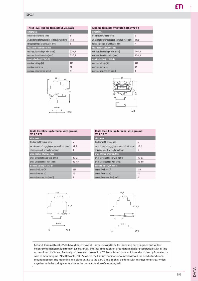
Three level line-up terminal VS 2,5 NAI3dimensionsthickness of terminal [mm]
av. tolerance of engaging on terminals rail [mm]stripping length of conductor [mm]cross-section of conductorscross-section of single wire [mm2]cross-section of fine wire [mm2]nominal value (IEC 947-1) nominal voltage [V]nominal current [A]nominal cross-section [mm2]
Line-up terminal with fuse holder VSV 4dimensionsthickness of terminal [mm]
av. tolerance of engaging on terminals rail [mm]stripping length of conductor [mm]cross-section of conductorscross-section of single wire [mm2]cross-section of fine wire [mm2]nominal value (IEC 947-1) nominal voltage [V]nominal current [A]nominal cross-section [mm2]
Multi level line-up terminal with ground VS 2,5 PE2dimensionsthickness of terminal [mm]
av. tolerance of engaging on terminals rail [mm]stripping length of conductor [mm]cross-section of conductorscross-section of single wire [mm2]cross-section of fine wire [mm2]nominal value (IEC 947-1) nominal voltage [V]nominal current [A]nominal cross-section [mm2]
Multi level line-up terminal with groundVS 2,5 PE3dimensionsthickness of terminal [mm]
av. tolerance of engaging on terminals rail [mm]stripping length of conductor [mm]cross-section of conductorscross-section of single wire [mm2]cross-section of fine wire [mm2]nominal value (IEC 947-1) nominal voltage [V]nominal current [A]nominal cross-section [mm2]
Ground terminal blocks VSPE have different layout - they are closed type for insulating parts in green and yellow colour combination made from PA 6.6 materials. External dimensions of ground terminals are compatible with all line-up terminals of VSN and PA family of the same cross-section. With combined base which conducts directly from electric wire to mounting rail EN 50035 or EN 50022 where the line-up terminal is mounted without the need of additional mounting space. The mounting and dismounting to the bar 32 and 35 shall be done with an inner long screw which together with the spring washer assures the correct position of mounting rail.
356
M3
33
34
31,2
M3
32,7
34
34,6
M3
33,8
32,6
34,4
M3
48
4357
SPOJ
5,1
+0,28
0,3-4,00,3-2,5
440242,5
6
+0,28
0,3-6,00,3-4,0
440324,0
7,2
+0,28
0,3-4,00,3-4,0
344
7,5
+0,27
1,5-6,00,5-4,0
354
DA
TA
Mini line-up terminal VS 2,5 PAMdimensionsthickness of terminal [mm]
av. tolerance of engaging on terminals rail [mm]stripping length of conductor [mm]cross-section of conductorscross-section of single wire [mm2]cross-section of fine wire [mm2]nominal value (IEC 947-1) nominal voltage [V]nominal current [A]nominal cross-section [mm2]
Mini line-up terminal VS 4 PAMdimensionsthickness of terminal [mm]
av. tolerance of engaging on terminals rail [mm]stripping length of conductor [mm]cross-section of conductorscross-section of single wire [mm2] cross-section of fine wire [mm2]nominal value (IEC 947-1) nominal voltage [V]nominal current [A]nominal cross-section [mm2]
Ground terminal VS 4 PEMdimensionsthickness of terminal [mm]
av. tolerance of engaging on terminals rail [mm]stripping length of conductor [mm]cross-section of conductorscross-section of single wire [mm2] cross-section of fine wire [mm2]nominal value (IEC 947-1) nominal current [A]nominal cross-section [mm2]
Ground terminal block VS 4 PEdimensionsthickness of terminal [mm]
av. tolerance of engaging on terminals rail [mm]stripping length of conductor [mm]cross-section of conductorscross-section of single wire [mm2]cross-section of fine wire [mm2]nominal value (IEC 947-1) nominal current [A]nominal cross-section [mm2]
357
9
+0,27
1,5-10,02,5-6,0
436
12
+0,210
4-166-1610-25
7016
16
+0,215
6-3510-3510-50
9535
42
+0,3
25x3
100019270
SPOJ
M3
53
55
57,5
M4
53
55
57,5
M6
6769,5
64,5
M8
88
4857
M8
DA
TA
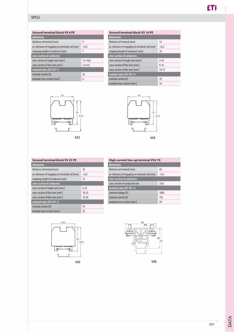
Ground terminal block VS 6 PEdimensionsthickness of terminal [mm]
av. tolerance of engaging on terminals rail [mm]stripping length of conductor [mm]cross-section of conductorscross-section of single wire [mm2]cross-section of fine wire [mm2]nominal value (IEC 947-1) nominal current [A]nominal cross-section [mm2]
Ground terminal block VS 16 PEdimensionsthickness of terminal [mm]
av. tolerance of engaging on terminals rail [mm]stripping length of conductor [mm]cross-section of conductorscross-section of single wire [mm2]cross-section of fine wire [mm2]cross-section of fine wire [mm2]nominal value (IEC 947-1) nominal current [A]nominal cross-section [mm2]
Ground terminal block VS 35 PEdimensionsthickness of terminal [mm]
av. tolerance of engaging on terminals rail [mm]stripping length of conductor [mm]cross-section of conductorscross-section of single wire [mm2]cross-section of fine wire [mm2]cross-section of fine wire [mm2]nominal value (IEC 947-1) nominal current [A]nominal cross-section [mm2]
High current line-up terminal VSU 70dimensionsthickness of terminal [mm]
av. tolerance of engaging on terminals rail [mm]cross-section of conductorscross-section of conduction railnominal value (IEC 947-1) nominal voltage [V]nominal current [A]nominal cross-section [mm2]
358
M8
88
4857
M8
M10
5748
88M10
M12
88
4857
M12
M12
88
4857
M12
42
+0,3
25x4
100023295
42
+0,3
25x5
1000269120
42
+0,3
25x8
1000353185
42
+0,3
25x10
1000415240
SPOJ
DA
TA
High current line-up terminal VSU 95dimensionsthickness of terminal [mm]
av. tolerance of engaging on terminals rail [mm]cross-section of conductorscross-section of conduction railnominal value (IEC 947-1) nominal voltage [V]nominal current [A]nominal cross-section [mm2]
High current line-up terminal VSU 120dimensionsthickness of terminal [mm]
av. tolerance of engaging on terminals rail [mm]cross-section of conductorscross-section of conduction railnominal value (IEC 947-1) nominal voltage [V]nominal current [A]nominal cross-section [mm2]
High current line-up terminal VSU 185dimensionsthickness of terminal [mm]
av. tolerance of engaging on terminals rail [mm]cross-section of conductorscross-section of conduction railnominal value (IEC 947-1) nominal voltage [V]nominal current [A]nominal cross-section [mm2]
High current line-up terminal VSU 240dimensionsthickness of terminal [mm]
av. tolerance of engaging on terminals rail [mm]cross-section of conductorscross-section of conduction railnominal value (IEC 947-1) nominal voltage [V]nominal current [A]nominal cross-section [mm2]
It maintains air gaps and creeping distances among cable lugs of conductors and protects the terminals against electric-shock hazard. It could be mounted on terminals VSU 70 to 150 connected with bridges, though in this case part of protective cover side wall should be cut along the line designed in the inferior. Cover, with the width identical to the width of terminals (42 mm) could be removed by means of screw driver. With terminals VSU 185 and 240 despite the bridging exclusively the usage of end plates KP VSU is required.
Protective cover ZP 200
359
SPOJ
In construction of distribution and switching equipment as well as in construction of electrical wiring there are various systems of either connection or wiring. The usage of wiring systems is increasing because they enable rapid intervention in the plant, i.e. substitution of conductors in case of failure. The advantage of wiring by means of plastic channels is the reduction of the assembly time to a minimum, space saving as well as aesthetic appearance. Channels are made of hard PVC and are resistant against acids, lyes and other chemicals. Constant temperature resistance is up to 60°C. Channels IKP consist of the lower part where the conductors are inserted and covers. The holes cut out from the side wall of the lower part of the channel are designed for the branching of the conductors to individual instruments. These holes are cut out so as to ease the insertion of conductor. In case a larger hole is required it could be enlarged with removal of the intermediate wall. The colour of channels is RAL 7030. Material is self-extin-guished according to UL 94 V-0 and can be used for ship-building.