36
Catalogue Models NB, WB, GN and GW Linear Bar Grilles www.air-diffusion.co.uk sales@air-diffusion.co.uk

2
Contents
Linear Bar Grilles
Page
Introduction Page 3
Models NB, WB, GN and GW Specifications Page 4
Selection Procedure Page 5
Models NB, 75mm – 125mm Selection Guide Page 6
Models NB, 150mm – 200mm Selection Guide Page 7
Models NB, 225mm – 275mm Selection Guide Page 8
Models NB, 300mm – 400mm Selection Guide Page 9
Models WB, 75mm – 125mm Selection Guide Page 10
Models WB, 150mm – 200mm Selection Guide Page 11
Models WB, 225mm – 275mm Selection Guide Page 12
Models WB, 300mm – 400mm Selection Guide Page 13
Models GN, 100mm – 200mm Selection Guide Page 14
Models GN, 250mm – 350mm Selection Guide Page 15
Models GN, 400mm Selection Guide Page 16
Models GW, 100mm – 200mm Selection Guide Page 17
Models GW, 250mm – 350mm Selection Guide Page 18
Models GW, 400mm Selection Guide Page 19
Flange Styles Page 20
Models NB, WB, GN and GW Dimensions Page 21
Installation Guide Page 22
Removable Core Details Page 23
Mitred Corners Page 24
Curved Sections Page 25
Ordering Information Linear Bar Page 26
Plenum Boxes Page 27
Plenum Box Dimensions PBL–1 Page 28
Plenum Box Dimensions PBL–2 Page 29
Plenum Box Dimensions PBL–3 Page 30
Plenum Box Dimensions PBL–4 Page 31
Plenum Box Dimensions Continued Page 32
Ordering Information Plenum Boxes Page 33
Product Range Page 34
Swegon R&D Academy Page 35

3 - Linear Bar Grilles
IntroductionThe Air Diffusion range of fixed blade Linear Bar Grillesincludes four model types to satisfy most applications. Eachmodel type is manufactured from robust extrudedaluminium sections to ensure the finished product offersfunctional strength and performance that also gives anattractive and aesthetically pleasing appearance.
Model NB narrow blade bar type linear grille incorporatesa 3.5mm wide blade on a 12.5mm pitch, with bladesavailable in 3 deflection angles 0°, 15° or 30°.
Model WB wide blade bar type linear grille incorporates a6.5mm wide blade on a 12.5mm pitch, with blades availablein 2 deflection angles 0° or 15°.
Model GN narrow blade bar type linear grille incorporatesa 3.5mm wide blade on a 19mm pitch, with blades availablein 3 deflection angles 0°, 15° or 30°.
Model GW wide blade bar type linear grille incorporates a6.5mm wide blade on a 19mm pitch, with blades availablein 2 deflection angles 0° or 15°.
A total of seven different flange styles are availableincluding tegular, bevel plaster, 20mm or 32mm widesurface mounting flange, alternatively an internal orexternal reverse angle flange may be provided.
The versatility of the range is demonstrated by the ability tooffer curved sections in either a vertical or horizontal plane,mitred corner sections, for sidewalls, soffits, cills or ceilingsand finally for added convenience hinged access panels toallow easy accessibility for controls or maintenance.
Standard colours are White RAL9010 (30% gloss) or SilverRAL9006 with a wide variety of alternative finishes alsoavailable on request.
Matching plenum boxes can be supplied to guarantee theperformance of the linear bar grille and plenum box,including a correctly sized spigot entry. An optionalopposed blade damper may also be supplied fitted to thegrille, if required.
The Models NB, WB, GN and GW may be used for eithersupply or extract systems and typically are suitable forinstallation in Shops, Showrooms, Hotels, ConferenceRooms, Offices, Reception Areas, Sports Halls and LeisureCentres.
4
Linear Bar Grilles
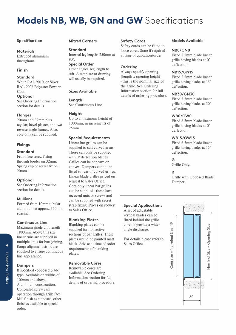
Models NB, WB, GN and GW Specifications
MaterialsExtruded aluminiumthroughout.
Finish
StandardWhite RAL 9010, or SilverRAL 9006 Polyester PowderCoat. OptionalSee Ordering Informationsection for details.
Flanges20mm and 32mm plustegular, bevel plaster, and tworeverse angle frames. Also,core only can be supplied.
Fixings
StandardFront face screw fixingthrough border on 32mm.Spring clip or secret fix on20mm.
OptionalSee Ordering Informationsection for details.
MullionsFormed from 10mm tubularaluminium at approx. 350mmspacing.
Continuous LineMaximum single unit length1800mm. Above this sizelinear runs are supplied inmultiple units for butt joining,flange alignment strips aresupplied to ensure continuousline appearance.
DampersIf specified - opposed bladetype. Available on widths of100mm and above.Aluminium construction.Concealed screw camoperation through grille face.Mill finish as standard, otherfinishes available to specialorder.
Mitred Corners
StandardInternal leg lengths 250mm at90°.Special OrderOther angles, leg length tosuit. A template or drawingwill usually be required.
Sizes Available
LengthSee Continuous Line.
HeightUp to a maximum height of1000mm, in increments of25mm.
Special RequirementsLinear bar grilles can besupplied to suit curved areas.These can only be suppliedwith 0° deflection blades.Grilles can be concave orconvex. Dampers cannot befitted to rear of curved grilles. Linear blade grilles priced onrequest to Sales Office.Core only linear bar grillescan be supplied - these haverecessed nuts or screws andcan be supplied with secretstrap fixing. Prices on requestto Sales Office.
Blanking PlatesBlanking plates can besupplied for non-activesections of bar grilles. Theseplates would be painted mattblack. Advise at time of orderrequirements of blankingplates.
Removable CoresRemovable cores areavailable. See OrderingInformation section for fulldetails of ordering procedure.
Safety CordsSafety cords can be fitted toloose cores. State if requiredat time of quotation/order.
OrderingAlways specify opening[length x opening height] - this is the nominal size ofthe grille. See OrderingInformation section for fulldetails of ordering procedure.
Specification
Cor
e siz
e =
Nor
min
al S
ize
–19
Nom
inal
Siz
e =
Ope
ning
Siz
e
60
Special ApplicationsA set of adjustablevertical blades can befitted behind the grillecore to provide a widerangle discharge.
For details please refer toSales Office.
Models Available
NB0/GN0Fixed 3.5mm blade lineargrille having blades at 0°deflection.
NB15/GN15Fixed 3.5mm blade lineargrille having blades at 15°deflection.
NB30/GN30Fixed 3.5mm blade lineargrille having blades at 30°deflection.
WB0/GW0Fixed 6.5mm blade lineargrille having blades at 0°deflection.
WB15/GW15Fixed 6.5mm blade lineargrille having blades at 15°deflection.
GGrille Only.
RGrille with Opposed BladeDamper.

5 - Linear Bar Grilles
NominalHeight Nominal Width - mm
mm 150 200 250 300 350 400 500 600 700 800 900 1000 1100 1200 100 .0077 .0110 .0143 .0176 .0209 .0242 .0308 .0374 .0440 .0506 .0572 .0638 .0704 .0770 150 .0136 .0193 .0251 .0309 .0367 .0425 .0541 .0657 .0773 .0889 .1005 .1121 .1237 .1353 200 .0276 .0359 .0442 .0525 .0608 .0774 .0940 .1106 .1272 .1438 .1604 .1770 .1936 250 .0467 .0574 .0683 .0791 .1007 .1223 .1439 .1655 .1871 .2087 .2303 .2519 300 .0708 .0841 .0974 .1240 .1506 .1772 .2038 .2304 .2570 .2836 .3102 400 .1340 .1706 .2072 .2438 .2804 .3170 .3536 .3902 .4268 500 .2172 .2638 .3104 .3570 .4036 .4502 .4968 .5434 600 .3204 .3770 .4336 .4902 .5468 .6034 .6600
Models NB, WB, GN and GW Selection Procedure
Free Area Factors:GN = 0.85GW = 0.70NB = 0.65WB = 0.50Based on 300 x 300 nominal size, the figures above may vary by 5% dependent on grille size.
Core area (m2)
Throw is based on a temperature differential of 10°C coolingto a terminal velocity of 0.25 m/s with a room height of 2.7when mounted flush with an unobstructed ceiling.
Pressure measurement is static pressure based on a bulkheadarrangement.
NR Values include –8dB room absorption and are calculatedas per BS 8233:2014 Anex B (NR = dbA –6).
Aerodynamic testing carried out in general accordance to BS EN 12238:2001 (Ventilation for buildings - Air Terminaldevices - Aerodynamic testing and rating for mixed flowapplications).
Acoustic data based on previous Catalogue. In future it shouldbe carried out in general accordance to BS EN ISO 5135:1999Acoustics. Determination of sound power levels of noise fromair-terminal devices, air terminal units, dampers and valves bymeasurement in reverberation room, or equivalent.
NR15
NR20
NR10
NR25
NR30
NR35
NR40
125mm Grille Height NB5.0
4.5
4.0
3.5
3.0
2.5
2.0
1.5
1.0
0.5
0.0
25.0
22.5
20.0
17.5
15.0
12.5
10.0
7.5
5.0
2.5
0.075 100 125 150 175 200 225 250 275 300 325 350 375
Pres
sure
(Pa
)
Volume l /s/m
Thro
w (
m)
Vt 0.25 m/s
Pressure
Selection Example
Volume 225 l/s/m
Pressure 8.5 Pa
Throw 3M (Vt 0.25 m/s)
Sound NR 25

NR15
NR20
NR25
NR30
NR35
NR40
NR15
NR20
NR10
NR25
NR30
NR35
NR40
NR15
NR20
NR25
NR30
NR35
NR40
75mm Grille Height
100mm Grille Height
125mm Grille Height
25
20
15
10
5
0
4
35
30
25
20
15
10
5
0
6
5
4
3
2
1
0
5.0
4.5
4.0
3.5
3.0
2.5
2.0
1.5
1.0
0.5
0.0
25.0
22.5
20.0
17.5
15.0
12.5
10.0
7.5
5.0
2.5
0.075 100 125 150 175 200 225 250 275 300 325 350 375
3
2
1
0
50 75 100 125 150 175 200 225 250 2750 300
75 100 125 150 175 200 225 250 275 300 325
Pres
sure
(Pa
)Pr
essu
re (
Pa)
Pr
essu
re (
Pa)
Volume l /s/m
Volume l /s/m
Volume l /s/m
Thro
w (
m)
Thro
w (
m)
Th
row
(m
)
Vt 0.25 m/s
Pressure
Vt 0.25 m/s
Pressure
Vt 0.25 m/s
Pressure
6
Linear Bar Grilles
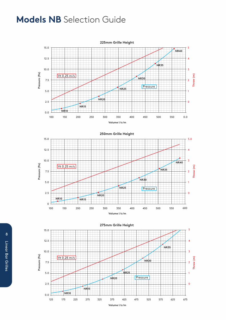
Models NB Selection Guide

NR15
NR20
NR25
NR30
NR35
150mm Grille Height5
4
3
2
1
0
12.5
15.0
10
7.5
5.0
2.5
0.0100 125 150 175 200 225 250 275 300 325 350 375 400
Pres
sure
(Pa
)
Volume l /s/m
Volume l /s/m
Thro
w (
m)Vt 0.25 m/s
Pressure
NR10 NR20
NR25
NR30
NR35
NR40
NR15
NR10
NR20
NR25
NR30
NR35
NR40
NR15
175mm Grille Height
200mm Grille Height
35
30
25
20
15
10
5
0
100 150 200 250 300 350 400 450 500
100 150 200 250 300 350 400 450 500
6
15.0
12.5
10.0
7.5
5.0
2.5
0
5
4
3
2
1
0
5
4
3
2
1
0
Pres
sure
(Pa
)Pr
essu
re (
Pa)
Volume l /s/m
Thro
w (
m)
Vt 0.25 m/s
Pressure
Vt 0.25 m/s
Pressure
7 - Linear Bar Grilles
Models NB Selection Guide
NR10NR20
NR25
NR30
NR35
NR40
NR15
NR10
NR20
NR25
NR30
NR35
NR40
NR15
225mm Grille Height
250mm Grille Height
15.0
12.5
10.0
7.5
5.0
2.5
0.0
5
15.0
12.5
10.0
7.5
5.0
2.5
0
5.0
4
3
2
1
0
4
3
2
1
0
100 150 200 250 300 350 400 450 500 550 0.0
100 150 200 250 300 350 400 450 500 550 600
Pres
sure
(Pa
)
Thro
w (
m)
Pres
sure
(Pa
)Pr
essu
re (
Pa)
Thro
w (
m)
Thro
w (
m)
Vt 0.25 m/s
Vt 0.25 m/s
Vt 0.25 m/s
Pressure
Pressure
Pressure
Volume l /s/m
Volume l /s/m
Volume l /s/m
NR10NR15
NR35
NR25
NR30
NR20
N
275mm Grille Height
125 175 225 275 325 375 425 475 525 575 625 675
12.5
15.0
10.0
7.5
5.0
2.5
0.0
4
5
3
2
1
0
8
Linear Bar Grilles
Models NB Selection Guide

9 - Linear Bar Grilles
Pres
sure
(Pa
)Pr
essu
re (
Pa)
Pres
sure
(Pa
)
Thro
w (
m)
Thro
w (
m)
Thro
w (
m)
Volume l /s/m
Volume l /s/m
Volume l /s/m
NR10NR15
NR20
NR25
NR30
NR35
NR5 NR15NR15
NR20
NR25
NR30
NR35
NR40
300mm Grille Height
350mm Grille Height
100 150 200 250 300 350 400 450
100 200 300 400 500 600 700 800 900 1000 1100
500 550 600 650 700 750 800 850 900
10
9
8
7
6
5
4
3
2
1
0
5.0
4.5
4.0
3.5
3.0
2.5
2.0
1.5
2.0
0.5
0.00
10
9
8
7
6
5
4
3
2
1
0
5
4
3
2
1
0
125 175 225 275 325 375 425 475 525 575 625 675 725
NR5 NR10NR15
NR20
NR25
NR30
NR35
NR40
400mm Grille Height8
7
6
5
4
3
2
1
0
4.0
3.5
3.0
2.5
2.0
1.5
1.0
0.5
0.0
Vt 0.25 m/s
Pressure
Vt 0.25 m/s
Pressure
Vt 0.25 m/s
Pressure
Models NB Selection Guide

NR10 NR15
NR20
NR25
NR30
NR35
NR20
NR15
NR25
NR30
NR35
NR20
NR15
NR25
NR30
NR35
75mm Grille Height
100mm Grille Height
125mm Grille Height
30
25
20
15
10
5
0
40
35
30
25
20
15
10
5
0100 125 150 175 200 225 250 275
0 25 50 75 100 125 150 175 200 225 250 275
50 75 100 125 150 175 200 225 250 275 300
300 325 350
6
5
4
3
2
1
0
6
40
35
30
25
20
15
10
5
0
5.0
3.5
2.0
0.5
0
5
4
3
2
1
0
Pres
sure
(Pa
)Pr
essu
re (
Pa)
Pres
sure
(Pa
)
Volume l /s/m
Volume l /s/m
Volume l /s/m
Thro
w (
m)
Thro
w (
m)
Thro
w (
m)
Vt 0.25 m/s
Pressure
Vt 0.25 m/s
Pressure
Vt 0.25 m/s
Pressure
10
Linear Bar Grilles
Models WB Selection Guide

NR15
NR20
NR25
NR30
NR35
NR40
NR10NR15
NR20
NR25
NR30
NR35
NR40
35
30
25
20
15
10
5
0100 150 200 250 300 350 400 450
6
24
22
20
18
1614
12
10
8
6
4
2
0100 150 200 250 300 350 400 450 500
5
4
3
2
1
0
5
4
3
2
1
0
Pres
sure
(Pa
)Pr
essu
re (
Pa)
Pres
sure
(Pa
)
Volume l /s/m
Volume l /s/m
Volume l /s/m
175mm Grille Height
200mm Grille Height
Thro
w (
m)
Thro
w (
m)
NR15
NR20
NR25
NR30
NR35
NR40
150mm Grille Height
100 125 150 175 200 225 250 275 300 325 350 375 400 425
40
35
30
25
20
15
10
5
0
6.0
3.5
1.0
Thro
w (
m)
Vt 0.25 m/s
Pressure
Vt 0.25 m/s
Pressure
Vt 0.25 m/s
Pressure
11 - Linear Bar Grilles
Models WB Selection Guide

275mm Grille Height
15.0
12.5
10.0
7.5
5.0
2.5
0.0
100 150 200 250 300 350 400
Volume (I/s /m)
Volume (I/s /m)
Volume (I/s /m)
450 500 550 600 650
5
4
3
2
1
0
Pres
sure
(Pa
)Pr
essu
re (
Pa)
Pres
sure
(Pa
)
Thro
w (
m)
Thro
w (
m)
Thro
w (
m)
NR15NR10
NR20
NR25
NR30
NR35
NR40
NR10NR15
NR20
NR25
NR30
NR35
NR40
NR10
NR15
NR20
NR25
NR30
NR35
NR40
24
22
20
18
16
14
12
10
8
6
4
2
100 150 200 250 300 350 400 450 500 550
5
24 5
4
3
2
1
0
22
20
18
16
14
12
10
8
6
4
2
0100 150 200 250 300 350 400 450 500 550 600
4
3
2
1
0
0
225mm Grille Height
250mm Grille Height
Vt 0.25 m/s
Pressure
Vt 0.25 m/s
Pressure
Vt 0.25 m/s
Pressure
12
Linear Bar Grilles
Models WB Selection Guide

300mm Grille Height
350mm Grille Height
400mm Grille Height
Volume (I/s /m)
Volume (I/s /m)
Volume (I/s /m)
100 150 200 250 400350300 450 500 550 600 650 700
15
6
5
4
3
2
1
0
12.5
10.0
7.5
5.0
2.5
0.0200100 300 400 500 600 700 800 900 1000
15.0 5
4
3
2
1
0
6
5
4
3
2
1
0
12.5
10.0
7.5
5.0
2.5
0.0
100 150 200 250 300 350 400 450 500 550 600 650 700 750 800 850
Pres
sure
(Pa
)
Thro
w (
m)
Pres
sure
(Pa
)
Thro
w (
m)
Pres
sure
(Pa
)
Thro
w (
m)
15.0
12.5
10.0
7.5
5.0
2.5
0.0
NR10
NR15
NR20
NR25
NR30
NR35
NR40
NR10
NR20
NR15
NR25
NR30
NR35
NR40
NR40
NR35
NR30
NR25
NR20
NR15NR10
NR5
Vt 0.25 m/s
Pressure
Vt 0.25 m/s
Pressure
Vt 0.25 m/s
Pressure
13 - Linear Bar Grilles
Models WB Selection Guide

NR5NR10
NR15
NR20
NR25
NR30
NR35
NR40
NR5NR10
NR15NR20
NR25
NR30
NR35
NR40
NR5NR10
NR15
NR25
NR30
NR35
NR40
NR20
N
100mm Grille Height
150mm Grille Height
200mm Grille Height
40
35
30
25
20
15
10
5
0
7
20.0
17.5
15.0
12.5
10.0
7.5
5.0
2.5
0
7
6
5
4
3
2
1
0
550525500457450425400375350325300275250225200175150
20.0
17.5
15.0
12.5
10
7.5
5.5
2.5
0.0
6
5
4
3
2
1
0
50 75 100 125 150 175 200 225 250 275 300 325 350
75 100 125 150 175 200 225 250 275 300 325 350 375 400 425 450
Pres
sure
(Pa
)Pr
essu
re (
Pa)
Volume l /s/m
Volume l /s/m
Volume l /s/m
Thro
w (
m)
Thro
w (
m)
Pres
sure
(Pa
)
Thro
w (
m)
7
6
5
4
3
2
1
0
Vt 0.25 m/s
Vt 0.25 m/s
Vt 0.25 m/s
Pressure
Pressure
Pressure
14
Linear Bar Grilles
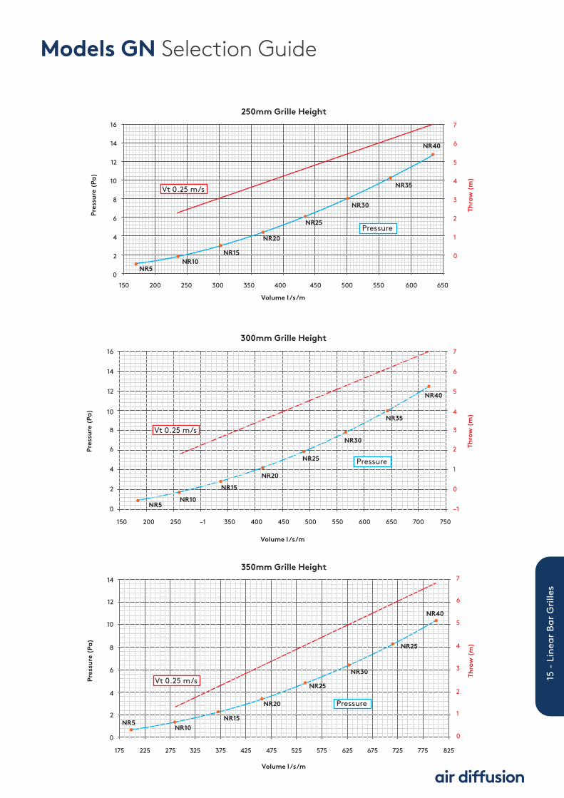
Models GN Selection Guide
NR5NR10
NR15
NR20
NR25
NR30
NR35
NR40
NR5NR10
NR20
NR15
NR25
NR30
NR25
NR40
300mm Grille Height
350mm Grille Height
16
14
12
10
8
6
4
2
0
7
6
5
4
3
2
1
0
–1
14
12
10
8
6
4
2
0
750
175 225 275 325 375 425 475 525 575 625 675 725 775 825
700650600550500450400350–1250200150
Pres
sure
(Pa
)
Thro
w (
m)
Pres
sure
(Pa
)
Thro
w (
m)
Volume l /s/m
Volume l /s/m
7
6
5
4
3
2
1
0
Vt 0.25 m/s
Vt 0.25 m/s
Pressure
Pressure
NR5NR10
NR15
NR20
NR25
NR30
NR35
NR40
250mm Grille Height16
150 200 250 300 350 400 450 500 550 600 650
14
12
10
8
6
4
2
0
Volume l /s/m
Pres
sure
(Pa
)
Thro
w (
m)
7
6
5
4
3
2
1
0
Vt 0.25 m/s
Pressure
15 - Linear Bar Grilles
Models GN Selection Guide

NR5NR10
NR15NR20
NR25
NR30
NR40
NR35
400mm Grille Height8
7
6
5
4
3
2
1
0
200 250 300 350 400 450 500 550 600 650 700 750 800 850 900
Pres
sure
(Pa
)
Thro
w (
m)
7
6
5
4
3
2
1
0
Volume l /s/m
Vt 0.25 m/s
Pressure
16
Linear Bar Grilles
Models GN Selection Guide

NR10 NR10NR15
NR20
NR30
NR35
NR40
NR25
NR5NR10
NR15
NR25
NR20
NR30
NR35
NR440
NR5NR10
NR15
NR20
NR25
NR30
NR35
NR40
100mm Grille Height
150mm Grille Height
200mm Grille Height
45.0
37.5
30
22.5
15.0
7.5
0.0
20.0
17.5
15.0
12.5
10
7.5
5.0
2.5
0.0
6
5
4
3
2
1
0
7
6
5
4
3
2
1
0
6
5
4
3
2
1
0
30
25
20
15
10
5
0
25 50 75 100 125 150 175 200 225 250 275 300
75 125 175 225 275 325 375 425 475
50 75 100 125 150 175 200 225 250 275 300 325 350 375 400
Pres
sure
(Pa
)
Volume l /s/m
Thro
w (
m)
Pres
sure
(Pa
)
Volume l /s/m
Thro
w (
m)
Pres
sure
(Pa
)
Volume l /s/m
Thro
w (
m)
Vt 0.25 m/s
Pressure
Vt 0.25 m/s
Pressure
Vt 0.25 m/s
Pressure
17 - Linear Bar Grilles
Models GW Selection Guide

NR5
NR5NR10
NR15NR20
NR25
NR30
NR35
NR40
NR10NR15
NR20
NR25
NR30
NR35
NR40
NR5NR10
NR15
NR20
NR25
NR30
NR35
NR40
14
12
10
8
6
4
2
0
6
5
4
3
2
1
0
100 150 200 250 300 350 400 450 500 550 600 650
10
9
8
7
6
5
4
3
2
1
0
4.0
3.5
3.0
2.5
2.0
1.5
1.0
0.5
0.0
125 175 225 275 325 375 425 475 525 575 625 675 725
Pres
sure
(Pa
)Pr
essu
re (
Pa)
Volume l /s/m
Volume l /s/m
Thro
w (
m)
Thro
w (
m)
250mm Grille Height7
6
5
4
3
2
1
0
20.0
17.5
15.0
12.5
10.0
7.5
5.0
2.5
0.0100 150 200 250 300 350 400 450 500 550
Pres
sure
(Pa
)
Volume l /s/m
Thro
w (
m)Vt 0.25 m/s
Pressure
300mm Grille Height
350mm Grille Height
Vt 0.25 m/s
Pressure
Vt 0.25 m/s
Pressure
18
Linear Bar Grilles
Models GW Selection Guide

NR40
NR35
NR30
NR25
NR20
NR35
NR10
NR5
10
9
8
7
6
5
4
3
2
1
0
3.0
2.5
2.0
1.5
1.0
0.5
0.0
100 150 200 250 300 350 400 450 500 550 600 650 700 750 800
Pres
sure
(Pa
)
Volume l /s/m
Thro
w (
m)
400mm Grille Height
Vt 0.25 m/s
Pressure
19 - Linear Bar Grilles
Models GW Selection Guide

3.2
28.6 28.6
28.6
25.4
28.6
3.2
3.2
20 20
37
8
27
36
32
37
4
37
20
37
32
25
Flange Styles
32mm Linear Flange 20mm Linear Flange 32mm Bevel Linear Flange(Fixed Core Only)
32mm Beveledge Linear Flange(Removable Core Only)
20mm 8TW Linear Flange 4mm Linear Flange (4P)
All dimensions are in millimetres (mm)
Reverse Angle Flat Bar Frame Flanges
FBF25 Flat Bar Frame
RAI Internal Reverse Angle Flange RAE External Reverse Angle Flange
20
Linear Bar Grilles
Opposed blade volume control damper
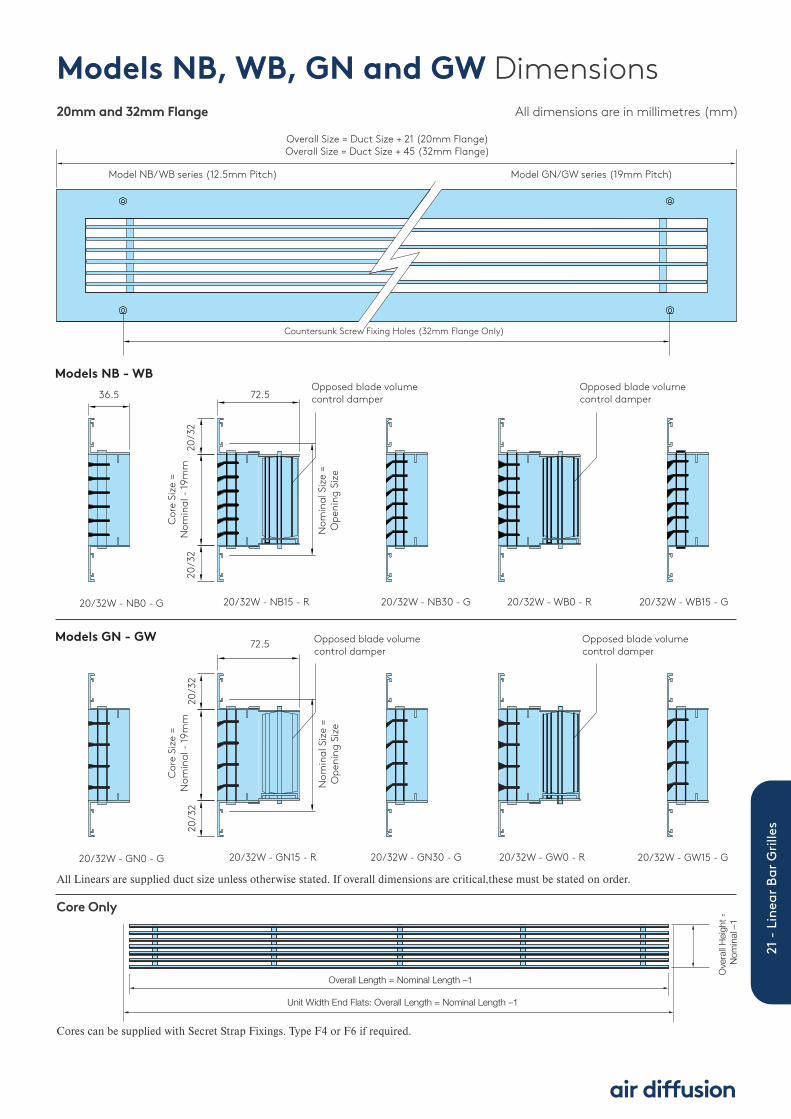
Models GN - GW Opposed blade volume control damper
20/32W - GN0 - G 20/32W - GN15 - R 20/32W - GN30 - G 20/32W - GW0 - R 20/32W - GW15 - G
Opposed blade volume control damper
Models NB - WBOpposed blade volume control damper
20/32W - NB0 - G 20/32W - NB15 - R 20/32W - NB30 - G 20/32W - WB0 - R 20/32W - WB15 - G
72.5
Cor
e Si
ze =
Nom
inal
- 19
mm
20/3
220
/32
Nom
inal
Siz
e =
Ope
ning
Siz
e
72.536.5
Cor
e Si
ze =
Nom
inal
- 19
mm
20/3
220
/32
Nom
inal
Siz
e =
Ope
ning
Siz
eCountersunk Screw Fixing Holes (32mm Flange Only)
Overall Size = Duct Size + 21 (20mm Flange)Overall Size = Duct Size + 45 (32mm Flange)
Model NB/WB series (12.5mm Pitch) Model GN/GW series (19mm Pitch)
Models NB, WB, GN and GW Dimensions All dimensions are in millimetres (mm)20mm and 32mm Flange
Overall Length = Nominal Length –1
Unit Width End Flats: Overall Length = Nominal Length –1
Ove
rall H
eight
=
Nom
inal –
1
Cores can be supplied with Secret Strap Fixings. Type F4 or F6 if required.
All Linears are supplied duct size unless otherwise stated. If overall dimensions are critical,these must be stated on order.
Core Only
21 - Linear Bar Grilles

22
Linear Bar Grilles
12m
mMating strap by others
Rear strap �tted to grille
‘U’ bracket by others
Rear strap �tted to grille
Type F1 Screw FixingStandard face countersunk holes forscrew fixing.
Type F2 Spring Clip FixingOptional spring clips.
Note:For satisfactory fixing require accuratelyformed opening or duct with firm sides.Not suitable for ceiling or high sidewallinstallation.
Type F4 Secret Rear Strap Fixing onlyOptional rear strap.
Note:Mating strap by others.
Type F4/F6 Secret Strap and ‘U’ BracketFixingOptional rear strap plus mating ‘U’ bracket.
Note:Hemmed duct by others or plenums by us.
Installation Guide
Type F8 - Ceiling Alignment Clip(Details of ceiling system and clip to besupplied).

Side ViewTypical ClipArrangement Terry Clips
12.5 crs
Brass Ferrules
12.5 crs
Nominal Size
Overall Size = Nominal + 45mm (32w border)
Terry Clip Option (RT)
Brass Ferrule Option (RB)
Removable Core Details All dimensions are in millimetres (mm)
23 - Linear Bar Grilles

Mitred CornersMitred Corners
Mitred corners are available and are manufactured to order. Mitres can be cut to angles ranging from 50° to 179°.Available in three styles for cill or sidewall.
250
Overall
Heigh
t
OverallHeight
250
Ø
Style M - Flat Corner (Cill)
Style M Interior - Inside Corner Concave (Sidewall)
Style M Exterior - Outside Corner Convex(Sidewall)
24
Linear Bar Grilles

25 - Linear Bar Grilles
A
B
Radi
us
Shown for ConvexVertical Grille
Ø
NominalOpeningSizeCurved Linear Grilles
Information required for manufacture of curved grilles:
A = Nominal Opening Size of ChordB = ArcC = Radius.
Curved grilles are supplied with 0° Deflection Blade.Where possible, a template should be supplied so thattrue radius can be supplied to fit opening.
Curved Sections
ExampleVertical grille can be supplied as core only or with flanges.
Horizontal Blades
Vertical Blades

26
Linear Bar Grilles
Flange Style Model Type Damper Core Fixing Finish
32C NB15 R FC F0 3
Ordering Information Linear BarTo order a cleated 20mm Flange Narrow Blade Fixed Core 15 Degree Blade with no fixing holes, finished RAL9010 white.This model would normally be written as: 20C - NB15 - R - FC - F0 - 3.
0 Mill extruded aluminium.
2 Silver RAL 9006 PolyesterPowder Coat finish.
3 White RAL 9010 (30%gloss) Polyester PowderCoat finish.
4 Black RAL 9005 PolyesterPowder Coat finish.
5 Brushed (linished) naturalaluminium face surfaces(32C or 32W flange only).
6 Special finish to bespecified external to themodel reference.
7 White RAL 9003 (30%gloss) Polyester PowderCoat finish.
16White RAL 9016 (30%gloss) Polyester PowderCoat finish.
20C 20mm flangewithmechanicallycleated corners.
20W 20mm flangewith fully weldedcorners.
32BW 32mm widebevel edgeflange.
32C 32mm flangewithmechanicallycleated corners.
32W 32mm flangewith fully weldedcorners.
27BW 27mm wide bevel edgeflange.
25TW8 28mm steppedflange to suit8mm ‘tegular’style ceiling grid.
4P Linear plasterflange.
RAI Reversed angleflange internal.
RAE Reversed angleflange external.
NB0 Fixed Blade Linear with3.5mm Blade 0° deflectionand 12.5mm pitch.
NB15Fixed Blade Linear with3.5mm Blade 15° deflectionand 12.5mm pitch.
NB30Fixed Blade Linear with3.5mm Blade 30° deflectionand 12.5mm pitch.
WB0 Fixed Blade Linear with6.5mm Blade 0° deflectionand 12.5mm pitch.
WB15Fixed Blade Linear with6.5mm Blade 15° deflectionand 12.5mm pitch.
GN0 Fixed Blade 0° Narrow BladeGrille with 19mm pitch.
GN15 Fixed Blade 15° NarrowBlade Grille with 19mmpitch.
GN30Fixed Blade 30° NarrowBlade Grille with 19mmpitch.
GW0 Fixed Blade 0° Wide BladeGrille with 19mm pitch.
GW15 Fixed Blade 15° Wide BladeGrille with 19mm pitch.
R Registers(grille withdampers).
G Grille only.
RB Removable Corevia Brass Ferrule.
RT Removable Corevia Terry Clip.
FC Fixed Core.
F0 No fixing (e.g. for ‘lay-in’ fixing or wherefixing holes are drilledon site).
F1 Countersunk screwfixing holes in flanges.(Not available with20C or 20W flange).
F2 Spring Clip - forfriction fitting toaccurate prepared openings (not suitablefor ceilings).
F4 Mating Strap - matingstrap in duct oropening provided byothers.
F6 ‘U’ bracket fixing withmating strap fitted togrille.
F8 Ceiling clip (detail tobe supplied, i.e. type of ceiling, spring tee).
Note: Redesign may occur whichsupersedes the information in thisbrochure.
Note: Special applications for grilleswith rear set of vanes please refer topage 4.
Example
Important Note: If the overall size is critical then it must be clearly stated on the order. All orders must be addressed to Swegon Air Management Ltd.

27 - Linear Bar Grilles
Plenum BoxesSupplied unlined as standardwith side entry spigot. Grillesare attached by either pop rivetor PK screw through neck ofgrille.
Plenum boxes can be suppliedinternally lined with 6mm class“O” foam at extra cost.
Plenum Boxes
Pressure Drops and Sound Rating Spigot Velocity m/s 1.5 2.0 2.5 3.0 3.5 4.0Pressure Drop Pa* 2 4 6 8 12 16Sound Power Level NR* - - 25 30 35 40* The figures given are approximate - dependent upon spigot entry conditions.
Spigot Velocity m/sDiameter (mm) 1.5 2.0 2.5 3.0 3.5 4.0
100 10 15 19 22 26 30 125 18 24 30 35 41 47 150 25 34 42 51 60 68 175 35 46 58 70 82 94 200 45 60 75 91 109 121 225 58 77 96 117 137 151 250 71 95 120 142 170 191 275 86 115 145 172 205 230 300 103 139 172 208 240 275 325 120 160 200 240 280 320 350 140 188 235 280 328 375 400 185 245 310 370 430 495
The pressure drop given isfor supply grille withdamper fully open. Whenthe grille is installed withplenum box, the pressureloss of the box has to beadded to the grille.
Plenum Box Spigot Volumes (l/s)
Specifications
MaterialStandard is a minimum of 0.7mmthick galvanised steel.
ConstructionPlenum boxes are generally fabricatedin 3 sections having indented ends,which are either mechanically joinedor spot welded to form an airtightseal. Flush ends (no indents) are alsoavailable. As standard, spigots areside entry and located centrally. Allboxes are supplied with plain edges,as standard, (F0 fixing).
Installation OptionsFor plenum boxes having flush endsindented separate hangingbrackets/fixing lugs need to be fitted toallow independent support of diffuserand plenum box.
AccessoriesJoggled style plenum boxes or panadapters.Spigot dampers include; quadrant,teleflex operation or cord operated.6mm thick Class ‘O’ internal lining. Equalising grids (50% free areaperforated mesh). Fixing lugs or special fixings (by others).Flush Ends (No Indent).
FinishSelf finish galvanised steel as standard.

H (
Exte
rnal
)
W (Internal)
X V V V V
Y (External)D (Nominal) D (Nominal) D (Nominal) D (Nominal)
D (Nominal)
65
9
A
Detail AIndented Detail
L (Internal)
28
Linear Bar Grilles
Plenum Box DimensionsType PBL-1 Indented All dimensions are in millimetres (mm)
Type PBL-1 Dimension Key
L - Length of Plenum (Internal)
W - Width of Plenum (Internal)
H - Height of Plenum (External)
C - Height of Cut-out (from bottom edge)
R - Lining Cutback distance (from bottom edge)
D - Nominal Spigot diameter
A - Square Spigot Width (Nominal)
B - Square Spigot Height (Nominal)
V - Spigot Spacing (Between centres)
X - Spigot Start Dimension ( Internal face)
Y - Spigot Vertical Position (External face)
G - Equalising Grid Length (Overall)
Z - Equalising Grid Height (from bottom edge)
Top Face
Face Front

X (Internal) V V V V
W (Internal)
D (Nominal)
9
A
Detail AIndented Detail
D (Nominal) D (Nominal) D (Nominal) D (Nominal)
Y (External)
L (Internal)
H (
Exte
rnal
)
65
Plenum Box DimensionsType PBL-2 Indented All dimensions are in millimetres (mm)
Type PBL-2 Dimension Key
L - Length of Plenum (Internal)
W - Width of Plenum (Internal)
H - Height of Plenum (External)
C - Height of Cut-out (from bottom edge)
R - Lining Cutback distance (from bottom edge)
D - Nominal Spigot diameter
A - Square Spigot Width (Nominal)
B - Square Spigot Height (Nominal)
V - Spigot Spacing (Between centres)
X - Spigot Start Dimension ( Internal face)
Y - Spigot Vertical Position (External face)
G - Equalising Grid Length (Overall)
Z - Equalising Grid Height (from bottom edge)
Top Face
Face Front
29 - Linear Bar Grilles

30
Linear Bar Grilles
V V V V
X (Internal) + 9
H (
Exte
rnal
)W
(In
tern
al)
D (Nominal) D (Nominal) D (Nominal) D (Nominal) D (Nominal)
L (Internal) + 18L (Internal) = Lo (Internal) Q (External) Wo (Internal)
Ko (External)Y (External)
65
Plenum Box DimensionsType PBL-3 Indented All dimensions are in millimetres (mm)
Type PBL-3 Dimension Key
L - Length of Plenum (Internal)
W - Width of Plenum (Internal)
H - Height of Plenum (External)
C - Height of Cut-out (from bottom edge)
R - Lining Cutback distance (from bottom edge)
D - Nominal Spigot diameter
A - Square Spigot Width (Nominal)
B - Square Spigot Height (Nominal)
V - Spigot Spacing (Between centres)
X - Spigot Start Dimension ( Internal face)
Y - Spigot Vertical Position (External face)
G - Equalising Grid Length (Overall)
Z - Equalising Grid Height (from bottom edge)
Wo - Outlet Width of Plenum (Internal)
Ko - Outlet Height of Plenum (External)
Q - Outlet Width Offset (External)
P - Outlet Length Offset (External)
Di - Circular Adaptor Spigot Diameter (Nominal)
Top Face
Face Front

31 - Linear Bar Grilles
Plenum Box DimensionsType PBL-4 Indented All dimensions are in millimetres (mm)
V V V V
W (
Inte
rnal
)H
(Ex
tern
al)
D (Nominal)
X (Internal) + 9
D (Nominal) D (Nominal) D (Nominal) D (Nominal)
Y (External)
L (Internal) + 18L (Internal) = Lo (Internal)
Q (External) Wo (Internal)
Ko (External)
(Y Ref.)
65
Type PBL-4 Dimension Key
L - Length of Plenum (Internal)
W - Width of Plenum (Internal)
H - Height of Plenum (External)
C - Height of Cut-out (from bottom edge)
R - Lining Cutback distance (from bottom edge)
D - Nominal Spigot diameter
A - Square Spigot Width (Nominal)
B - Square Spigot Height (Nominal)
V - Spigot Spacing (Between centres)
X - Spigot Start Dimension ( Internal face)
Y - Spigot Vertical Position (External face)
G - Equalising Grid Length (Overall)
Z - Equalising Grid Height (from bottom edge)
Wo - Outlet Width of Plenum (Internal)
Ko - Outlet Height of Plenum (External)
Q - Outlet Width Offset (External)
P - Outlet Length Offset (External)
Di - Circular Adaptor Spigot Diameter (Nominal)
Top Face
Face Front

32
Linear Bar Grilles
Dimensions and Weights Model Ref Nominal Duct* Open Blade DW144 Casing Weight (Kg) Diameter Protrusion (mm) Leakage class
CB 100 — C 0.56
CB 125 — C 0.71
CB 150 — C 0.85
CB 160 — C 0.91
CB 200 — C 1.17
CB 250 20.5 C 1.53
CB 300 45.5 C 1.92
CB 315 53 C 2.05
CB 350 70.5 C 2.35
CB 355 73 C 2.40
Plenum Box Dimensions ContinuedManual Quadrant Control Damper All dimensions are in millimetres (mm)
NDD*: Nominal duct diameter. Actual sizes are in accordance with BSEN1506.
200
ND
D
50
50
50
60
75
50

33 - Linear Bar Grilles
Plenum Boxes
PBL-1 Linear Plenum Box witheither a circular or squareside entry spigot.
PBL-2 Linear Plenum Box havingeither a circular or squaretop entry spigot.
PBL-3 Linear Plenum Box withjoggle section having eithera circular or square sideentry spigot.
PBL-4 Linear Plenum Box withjoggle section having eithera circular or square topentry spigot.
U – Standard UnlinedPlenum Box.
L – 6mm Class ‘O’Internal Lining.
N – Plain spigot nodamper.
Q – Quadrant damper.
C – Cord operateddamper fitted to spigot.
0 – No options
2 – Equalising grid.
3 – Fixing lugs fitted toside of plenum.
4 – Profile ends on eachend of plenum.
5 – Hemmed Edge forsecret strap fixing.
Seeexamplebelow
Neck Size Plenum Height Circular Spigot Sq. /Rect. Spigot Centre Line Diameter Width x Height of Spigot L x W H ∅D C x E G
450 x 450 350 250 0 0
Dimensions PBL - 1, Example
OR
‘0’ Denotes Standard.
Ordering Information Plenum Boxes
Important Note: All orders must be addressed to Swegon Air Management Ltd.
Model Internal Lining Spigot Damper Options Dimensions
PBL-1 U N 0
Example

34
Linear Bar Grilles
Product Range
Flowbar HighCapacity Slot Diffuser
Linear Slot Diffuser Square andRectangular Diffuser
Circular CeilingDiffuser
Exhaust and Supply AirValves
Egg Crate Grilles Linear Narrow BladeBar Grille
Circular Floor Swirl Fixed Blade Grille Linear Floor Grille
Single DeflectionGrille
Perforated FaceCeiling Diffuser
Variable Air PatternCeiling Swirl Diffuser
Double DeflectionGrille
Ceiling Swirl Diffuser
Non Vision Grille Linear Wide Blade BarGrille
Security Grille Fixed Blade ExternalLouvre
Cylinder Jet Diffuser
DisplacementVentilation Diffuser
Fixed Blade LinearCeiling Diffuser
Jet Diffuser Panel Floor Grille
Note: Redesign mayoccur which supersedesthe information in thisbrochure. Please refer toour website for latestinformation.

35 - Linear Bar Grilles
The Swegon research and developmentacademy at Whitstable provides state ofthe art facilities for testing a completerange of products. It was designed inaccordance with BSRIArecommendations and benefits fromthird party annual assessment. It has awell equipped demonstration area wheretests can be witnessed by contractors,consultants and end clients. Third partwitnessing by BSRIA is available ifrequired.
The test facility is fitted with the latestequipment and exceeds therequirements of BS EN 12238:2001 (forair terminal devices aerodynamic testingand rating for mixed flow applications)with a test room size of 7.5m long x5.6m wide x 2.8m high. Ceiling heightsand floor voids can also be adjustabledepending on the test regime required.
A purpose designed air handling systemis able to supply conditioned air acrossa wide temperature range in bothheating and cooling modes withvolumes up to the equivalent of 20 airchanges per hour being available.
Sophisticated measuring and loggingequipment is able to monitor airvolumes, velocities, pressures andtemperatures as well as airflow patternvisualisation via the use of smokegeneration within the test laboratory.
Swegon R&D Academy

actionair | air diffusion | airfiltrera | airolution | naco
Stourbridge Rd, Bridgnorth,WV15 5BB, Shropshire, UK
The statements made in this brochure or by ourrepresentatives in consequence of any enquiries arising out of this document are given for information purposesonly. They are not intended to have any legal effect andthe company is not to be regarded as bound thereby.The company will only accept obligations which are expressly negotiated for and agreed and incorporated into a written agreement made with its customers.
Due to a policy of continuous product development thespecification and details contained herein are subject toalteration without prior notice.
Tel: +44 (0)1746 761921Email: [email protected]: air-diffusion.co.uk
LNNN00399 (2.0 - 07.18)


