HAL Id: hal-01510047 https://hal-enpc.archives-ouvertes.fr/hal-01510047 Submitted on 18 Apr 2017 HAL is a multi-disciplinary open access archive for the deposit and dissemination of sci- entific research documents, whether they are pub- lished or not. The documents may come from teaching and research institutions in France or abroad, or from public or private research centers. L’archive ouverte pluridisciplinaire HAL, est destinée au dépôt et à la diffusion de documents scientifiques de niveau recherche, publiés ou non, émanant des établissements d’enseignement et de recherche français ou étrangers, des laboratoires publics ou privés. Linear buckling of quadrangular and kagome gridshells: A comparative assessment Romain Mesnil, Cyril Douthe, Olivier Baverel, Bruno Léger To cite this version: Romain Mesnil, Cyril Douthe, Olivier Baverel, Bruno Léger. Linear buckling of quadrangular and kagome gridshells: A comparative assessment. Engineering Structures, Elsevier, 2017, 132, pp.337 - 348. 10.1016/j.engstruct.2016.11.039. hal-01510047
Transcript
HAL Id: hal-01510047https://hal-enpc.archives-ouvertes.fr/hal-01510047
Submitted on 18 Apr 2017
HAL is a multi-disciplinary open accessarchive for the deposit and dissemination of sci-entific research documents, whether they are pub-lished or not. The documents may come fromteaching and research institutions in France orabroad, or from public or private research centers.
L’archive ouverte pluridisciplinaire HAL, estdestinée au dépôt et à la diffusion de documentsscientifiques de niveau recherche, publiés ou non,émanant des établissements d’enseignement et derecherche français ou étrangers, des laboratoirespublics ou privés.
Linear buckling of quadrangular and kagome gridshells:A comparative assessment
Romain Mesnil, Cyril Douthe, Olivier Baverel, Bruno Léger
To cite this version:Romain Mesnil, Cyril Douthe, Olivier Baverel, Bruno Léger. Linear buckling of quadrangular andkagome gridshells: A comparative assessment. Engineering Structures, Elsevier, 2017, 132, pp.337 -348. �10.1016/j.engstruct.2016.11.039�. �hal-01510047�
Linear buckling of quadrangular and kagome gridshells: a comparative assessment
Romain Mesnila,b,∗, Cyril Douthea, Olivier Baverela, Bruno Legerb
aLaboratoire Navier, UMR 8205, Ecole des Ponts, IFSTTAR, CNRS, UPE, Champs-sur-Marne, FrancebBouygues Construction SA, Guyancourt, France
Abstract
The design of gridshells is subject to strong mechanical and fabrication constraints, which remain largely unexplored fornon-regular patterns. The aim of this article is to compare the structural performance of two kind of gridshells. Thefirst one is the kagome gridshell and it is derived from a non-regular pattern constituted of triangles and hexagons. Thesecond one results from a regular pattern of quadrangles unbraced by diagonal elements. A method is proposed to coverkagome gridshells with planar facets, which reduces considerably the cost of fabrication of the cladding.
The sensitivity of kagome gridshells to geometrical imperfections is discussed. The linearised buckling load of kagomegridshells is then compared to the one of quadrilateral gridshells. The most relevant design variables are considered inthe parametric study. Two building typologies are studied for symmetrical and non-symmetrical load cases: dome andbarrel vault. It reveals that the kagome gridshell outperforms quadrilateral gridshell for a very similar construction cost.
Grid-shells are structures made of beam elements thatact as continuous shells structures. The choice of agrid pattern influences both fabrication and structural be-haviour. For example, triangulated structures are knownto be stiffer than quadrangular meshes. Quadrangular gr-ishells rely on the bending stiffness of connections, whereastriangulated gridshells benefit from a shell-like behaviourwithout the need for rigid connections. The better struc-tural performance of triangular gridshells is however atthe cost of an increased node complexity due to highernode valence. In quadrangular meshes, panels are howevernot necessarily planar, and only specific curve networks onsurfaces or shape-generation strategies guarantee meshingwith planar quadrilaterals [1, 2, 3, 4]. There is thus a nec-essary trade-off between design freedom and fabricationconstraints.
This article focuses on a lesser known family of pattern,called kagome grid pattern, composed from triangles andhexagons and represented in Figure 1. The kagome patterncan be found in Japanese basketry, where the membersare woven. We focus here on applications to structuralengineering and consider non-woven pattern, where all theneutral axes of the beams are concomitant, and the beamsare rigorously straight. Like quadrilateral grids, kagomegrids present a node valence of four, which indicates areasonable cost of fabrication. Among other usage, kagome
grids have been used in the architecture of Shigeru Ban andfor ornamentation purpose. Their structural possibilitiesremain however largely unexplored, and little is known onthe planarity of the facets, a key element to the economyof the envelope.
Figure 1: A kagome grid pattern covered with planar facets generatedwith the method described in this paper.
Kagome grid pattern and quadrilateral grid patternhave the same node valence, and their structural behaviourcan be compared qualitatively. Rigid connections are nec-essary to guarantee in-plane shear stiffness of these pat-terns. However, their relatively low node valence assuresthe existence of a large families of torsion-free beam offsetscompatible with the use of deep beams [5]. Kagome andquadrilateral grid patterns can thus be built with very sim-ilar technological solutions. Their relative structural per-formances is however not quantified and will be studied inthis paper, whose main contributions are:
Preprint submitted to Engineering Structures November 15, 2016
• a strategy for the covering of kagome meshes withplanar facets, demonstrating that they could bea viable alternative to triangular or quadrilateralmeshes;
• a parametric study comparing the linear bucklingload of kagome gridshells with quadrangular grid-shells for shapes covered with planar facets;
• design guidelines for kagome gridshells.
The article is organised as follows: the first sectionpresents the motivations for this work as well as relevantliterature in the field of mechanics of gridshells. The sec-ond section introduces the methodology chosen to assessthe structural behaviour of kagome gridshells. The thirdsection gathers the results of the conducted parametricstudy. A brief discussion and conclusion sum up the con-tributions of the present work.
1.1. Previous work on the mechanics of single-layered lat-tice shells
The structural behaviour of gridshells is usually gov-erned by non-linear effects, most noticeably buckling [6].Four buckling configurations can be observed in gridshells:
• Global buckling in the manner of a shell;
• Member buckling;
• Snap-through of one node;
• In-plane rotation of one node.
Some design recommendations, often emphasizing simpleshapes, like spherical cupolas have been published. Gioncupublished a state of the art on the buckling of reticulatedstructures in 1995 [7]. A report produced by the Work-ing Group of the International Association for Shells andSpatial Structures (IASS) in 2005 completes this reviewwith analytical and numerical results, demonstrating theimportant advances made in that field [8]. A novel issueis to be published in 2016. A design guide for the stabilityof reticulated shells with a thorough literature review isproposed in [9], showing a great mastery of this topic.
These guidelines identify two approaches to evaluatethe structural behaviour of a grid structure: homogeni-sation methods and numerical experiments. This articleestablishes a parametric numerical study, and uses previ-ous work on homogenisation of grid structures to commentthe numerical results.
1.1.1. Homogenisation and equivalent shell thickness
Homogenisation techniques aim to formulate an equiv-alent continuous behaviour of a heterogeneous structurewith a cell repeated periodically. These methods use thesuperposition principle and usually work well for struc-tures with a linear behaviour [10]. They have been suc-cessfully used for planar grids [11], but a rigorous extension
to gridshells is difficult because of the loss of periodicity,due to the variations of curvature. A discussion on thistopic is proposed by Gioncu and Balut [12].
The advantage of equivalent thickness model is thatthey provide structural engineers with simpler formulasand can be of practical interest for conceptual structuraldesign. Some attempts to provide equivalent shell thick-ness have been used in previous studies [13, 14, 15, 16].However, these models do not allow for the modelling oflocalised buckling and the study of the influence of imper-fections for shell structures remains tedious for non-trivialshapes. Nowadays, the ever-growing computational powermakes the use of finite element modelling and non-linearanalysis ubiquitous in practice, and numerical simulationsare often preferred to homogenisation formulæ.
1.1.2. Numerical experiments
Numerical methods are used for the practical design ofgridshells, because they allow for integration of complexissues, like material nonlinearities or geometrical imperfec-tions. Some guidelines for the analysis of reticulated domeshave been proposed by Kato et al. [17, 18]: these stud-ies introduced geometrical imperfections and semi-rigidnodes. Bulenda and Knippers [6] performed parametricstudies on domes and barrels vaults and evaluated the in-fluence of imperfections on the stability of gridshells. Amore complete study using finite element analysis to eval-uate local node stiffness of patented connections has beenperformed by Huang et al. [19]. Bruno et al. assessedthe influence of nodal imperfection and of Eigenmode Im-perfection Method (EIM) more recently [20]. Malek et al.[15] performed numerical investigations on the bucklingof spherical cap domes and considered geometrical values,like grid spacing, or height over span ratio, as parameters.This approach lead to recommendations for the design ofgridshells with triangular or quadrangular layout.
Other studies have evaluated the influence of residualstresses in elastic gridshells [16, 21]. A more completeanalysis was performed on the elastic gridshell built for theSoliday’s festival in Paris, considering accidental ruin ofsome members [22]. These studies show that high bendingstresses due to the form-finding process of elastic gridshellshave little influence on the buckling capacity of domes.Such procedures could be extended to steel structures, inorder to assess the influence of other residual stress fieldson the stability of gridshells.
1.2. Imperfections
There are many differences between the ideal numericalshell models and the built structures. These differences, orimperfections can be of different nature: loads, geometry,material, residual stresses in the members. Thin shells areknown to be sensitive to imperfections [23]. These param-eters are often set as a global geometrical imperfections.Gioncu and Balut also point out that geometrical imper-fection tend to govern over material nonlinearities for largespan structures [12].
2
Typically, the difference between the built geometryand the computed model is of a few centimeters at most[24]. It is therefore necessary to introduce a norm, in or-der to asses realistic imperfections. In the following, thenorm ‖ · ‖∞ defined as the maximal displacement is used.Bulenda and Knippers propose a higher bound of L/500for the imperfection with the infinity norm [6]. Based ondata on the precision requirements for built project [25],Malek et al. studied an imperfection of 3mm [15].
The choice of the shape function is discussed in Section2.4. The first buckling mode is recommended by designcodes, and was used for example for the design of the roofof the British Museum and the Palacio de Comunicaciones[26, 25]. However, different studies show that other imper-fections shapes should be considered, as they result in abigger reduction of the buckling capacity of gridshells. Ex-amples of such shapes can be found in [6] with the use ofdynamic eigenmodes, and a discussion on the choice of ap-propriate imperfections is proposed in [20]. It has to be no-ticed that there is no closed-form solution on the worst im-perfection possible, some studies even demonstrated thathigher order eigenmodes can have a more critical effecton the reduction of buckling capacity [27]. The purposeof this paper being to compare relative performance be-tween kagome grid pattern and quadrilateral pattern, wewill consider the imperfections most commonly used incurrent practice and limit the sensitivity analysis of section2.4 to imperfection shapes following the first eigenmode.
2. Methodology
2.1. Numerical experiment and choice of the parameters
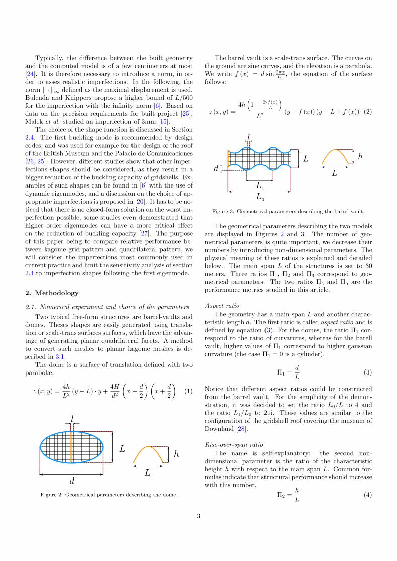
Two typical free-form structures are barrel-vaults anddomes. Theses shapes are easily generated using transla-tion or scale-trans surfaces surfaces, which have the advan-tage of generating planar quadrilateral facets. A methodto convert such meshes to planar kagome meshes is de-scribed in 3.1.
The dome is a surface of translation defined with twoparabolæ.
z (x, y) =4h
L2(y − L) · y +
4H
d2
(x− d
2
)(x+
d
2
)(1)
d
L
L
h
l
Figure 2: Geometrical parameters describing the dome.
The barrel vault is a scale-trans surface. The curves onthe ground are sine curves, and the elevation is a parabola.We write f (x) = d sin 2πx
L1, the equation of the surface
follows:
z (x, y) =4h(
1− 2·f(x)L
)L2
(y − f (x)) (y − L+ f (x)) (2)
L
h
L0
L1
L
l
d
Figure 3: Geometrical parameters describing the barrel vault.
The geometrical parameters describing the two modelsare displayed in Figures 2 and 3. The number of geo-metrical parameters is quite important, we decrease theirnumbers by introducing non-dimensional parameters. Thephysical meaning of these ratios is explained and detailedbelow. The main span L of the structures is set to 30meters. Three ratios Π1, Π2 and Π3 correspond to geo-metrical parameters. The two ratios Π4 and Π5 are theperformance metrics studied in this article.
Aspect ratio
The geometry has a main span L and another charac-teristic length d. The first ratio is called aspect ratio and isdefined by equation (3). For the domes, the ratio Π1 cor-respond to the ratio of curvatures, whereas for the barellvault, higher values of Π1 correspond to higher gaussiancurvature (the case Π1 = 0 is a cylinder).
Π1 =d
L(3)
Notice that different aspect ratios could be constructedfrom the barrel vault. For the simplicity of the demon-stration, it was decided to set the ratio L0/L to 4 andthe ratio L1/L0 to 2.5. These values are similar to theconfiguration of the gridshell roof covering the museum ofDownland [28].
Rise-over-span ratio
The name is self-explanatory: the second non-dimensional parameter is the ratio of the characteristicheight h with respect to the main span L. Common for-mulas indicate that structural performance should increasewith this number.
Π2 =h
L(4)
3
Structural density ratio
We consider here the grids to have a mean memberlength of l. The comparison of this number to the mainspan, as done in equation (5) gives indications on the gridcoarseness.
Π3 =l
L(5)
Buckling ratio
The last parameter compares the buckling pressure pcrfound by linear buckling analysis to the member bendingstiffness EI/L4. The number described by equation (6) isthe value that is compared between kagome and quadri-lateral meshes. The ratio I/L4 being kept constant in thisstudy, the buckling ratio will be a measure of the stiffnessdue to the form and mesh topology independently of thesection properties.
Π4 =pcrL
4
EI(6)
Notice that only the quadratic moment of inertia I isconsidered. A comparable non-dimensional number couldbe constructed with the span L, the axial stiffness EA andthe critical pressure pcr. However, it is a well-known factthat member shortening has more impact on very shallowstructures which won’t be considered in our study.
Structural efficiency
We introduce finally a variable, later called structuralefficiency, in order to compare the performance of kagomeand quadrilateral grid pattern. The parameter is definedas:
Π5 =pcr.A
m · g(7)
where A is the horizontal surface covered, m the mass ofthe structure and g the acceleration due to gravitationalforces on Earth. The number defined by equation (7) com-pares the total resultant of vertical forces to the resul-tant of gravity forces. It must be noticed that for a samestructural density, i.e. individual member length, the totallength of members differs between the kagome and quadri-lateral grid. For a square grid with edge length l, the totalbeam length per unit area is 2
l . For a kagome grid madeof regular hexagons and triangles and edge length l, the
total beam length per unit area is√
3l . From this simple
case, an estimation of the ratio of the masses is given by:
mKagome
mQuad∼√
3
2' 86% (8)
In other terms, for a same structural density, the kagomegrid is slightly lighter than the quadrilateral grid. This dif-ference justifies the fact to look more closely at the struc-tural efficiency, and not only at the buckling load.
Table 1 sums up the range of variations of each pa-rameter. It is chosen to fit existing designs: for exam-ple the rise-over-span ratio remain in general superior to
0.1 to avoid high bending stresses or snap-through. Thestructural density are chosen so that the minimal mem-ber length is 1.253, a reasonable value compared to builtprojects. Each set of geometrical parameters generates ageometry for a quadrilateral and a kagome grid. Two loadcases are considered, as discussed in Section 2.2. The para-metric study proposed in this paper consists thus of 500linear buckling analysis and several fully nonlinear analysisfor the study on imperfections sensitivity.
2.2. Material, loads and boundary conditions
The material used is steel, and we restrict our study toa linear elastic material law. Detailed studies with plas-ticity have been made previously and are reviewed in [8].These studies are necessary to evaluate with high fidelitythe post-buckling behaviour of gridshells, at the cost ofhigh computational effort. In the first steps of the designprocess, engineers need to perform many analyses, oftenwith simplified assumptions and a linearised buckling loadis already a good indicator of the structural performance.It was already chosen as design criterion in [15] and [21].The modelling hypothesis follow:
• the supports are pin joints with full translational re-straint;
• the joints are assumed to be fully rigid;
• in the barrel vault, the arches are simply-supported;
• distributed loads are replaced by concentrated loadsat connections.
The members are made of circular hollow section, witha wall thickness of 10mm and a diameter of 200mm for thedome and the barrel vault. With these geometries, thereis no difference between Iy, Iz, and torsional buckling ofmembers is not possible, which simplifies the parametricstudy. In the followings, we use beam elements with threeelements per member. This subdivision allows to captureeventual localised buckling modes, which can arise in grid-shells.
Two load cases are considered: a uniform projectedvertical load of 1kPa and a non-symmetrical load of 1kPaapplied following the normal of the surfaces with the pat-tern of Figure 4.
+
- -
+
Figure 4: Areas of positive and negative pressure for the non-symmetrical load case, top view of Figure 2.
Current literature focuses more on uniform symmetri-cal load cases [15]. Koiter has shown than spherical capsare subject to geometrical imperfections for such load case,but not for concentrated load. Therefore, it is meaningful
Table 1: Variations of the parameters in the present study.
to consider this kind of load case in our sensitivity analysis.Furthermore, non-symmetrical load cases are known to bemore critical than symmetrical ones for buckling and of-ten govern the sizing of gridshells. The asymmetrical loadcase is thus also considered in order to provide guidance onsituations closer to the engineering practice. The chosenasymmetrical load represents here a wind load, which usu-ally features areas of positive and negative pressure. Windloads computed from the Eurocode can usually be decom-posed between a symmetrical and asymmetrical compo-nent. Since we already study a symmetrical load case, wefocus only on the non-symmetrical component of this load.
2.3. Buckling analysis
This study mainly adopts linear buckling analysis ofperfect gridshells. In addition, geometric non-linear anal-ysis on structures with imperfections are carried out topreliminary evaluate the effects of imperfections. In linearbuckling analysis, it is often considered that the stiffnessmatrix of a structure can be written as the sum of KE theelastic stiffness (independent of the applied load P) andof KG the geometric stiffness (which decreases here withP). The linear buckling analysis makes the assumptionthat the coefficients of KG vary linearly with the ampli-tude of P and finds thus couples of buckling factor anddisplacement vector (λ,Φ) so that:
(KE + λKG) ·Φ = 0 (9)
The non-linear buckling problem becomes thereforethe eigenvalue problem shown in equation (9), the lowesteigenvalue λ1 giving an estimate of the buckling capacityof the structures. The linearisation hypothesis is in facta Taylor development, and it is valid if the displacementsbefore buckling are small. In structures subject to largedeformations, like gridshells, the linear buckling analysiscan overestimate largely the real buckling capacity. Indetailed design, fully non-linear analysis is thus requiredto assess the bearing capacity of gridshells, but the lin-ear buckling analysis can be quickly estimated and can behelpful in conceptual design stage [15].
The analysis software used is Karamba, a plug-in in-tegrated with parametric CAD tools RhinocerosTMandGrasshopperTM[29, 30]. This software enables to performstructural analysis within a 3D-modelling environment,which considerably eases the design process for structuralengineers.
2.4. Influence of imperfections
This section focuses on the influence of imperfectionon kagome gridshells. The tested geometry is a dome sup-ported on a circular plan (Π1 = 1, Π2 = 0.2, Π3 = 1/32),and subject to a uniform vertical load. Figure 5 shows dif-ferent plots of linear buckling load pcr normalised by thelinear buckling load of the structure without imperfectionpcr,0 computed with different imperfection amplitudes forthe infinity norm. The kagome pattern is more sensitive toimperfections than the quadrangular pattern. For the am-plitude of L/500, the reduction of the linearised bucklingload is approximately 10%.
Figure 5: Influence of imperfection scale on the linear buckling load.
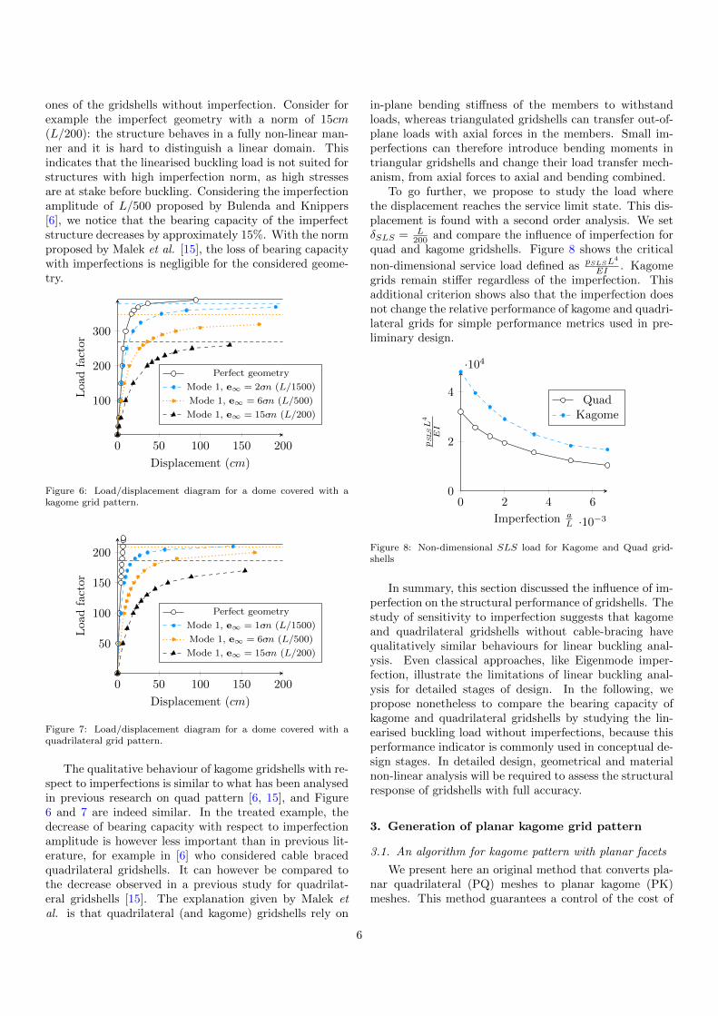
A second order analysis is thus performed on both per-fect and imperfect geometry to evaluate more preciselythe influence of imperfections. The load/displacement dia-grams for the kagome and quadrilateral gridshells obtainedare displayed in Figure 6 and 7 respectively. The four hor-izontal lines represent the linearised buckling loads. Threeimperfection amplitudes are considered: the first one is asmall imperfection (L/1500) and can be compared to theone used by Malek et al. [15], the second corresponds tothe (L/500), as proposed by Bulenda and Knippers [6],the third one is of (L/200) as recommended in EC3.
The structures with imperfections do not reach theirlinearised buckling loads, contrary to perfect structures.The load/displacement graphs are less curved than the
5
ones of the gridshells without imperfection. Consider forexample the imperfect geometry with a norm of 15cm(L/200): the structure behaves in a fully non-linear man-ner and it is hard to distinguish a linear domain. Thisindicates that the linearised buckling load is not suited forstructures with high imperfection norm, as high stressesare at stake before buckling. Considering the imperfectionamplitude of L/500 proposed by Bulenda and Knippers[6], we notice that the bearing capacity of the imperfectstructure decreases by approximately 15%. With the normproposed by Malek et al. [15], the loss of bearing capacitywith imperfections is negligible for the considered geome-try.
0 50 100 150 200
100
200
300
Displacement (cm)
Load
fact
or
Perfect geometry
Mode 1, e∞ = 2cm (L/1500)
Mode 1, e∞ = 6cm (L/500)
Mode 1, e∞ = 15cm (L/200)
Figure 6: Load/displacement diagram for a dome covered with akagome grid pattern.
0 50 100 150 200
50
100
150
200
Displacement (cm)
Loa
dfa
ctor
Perfect geometry
Mode 1, e∞ = 1cm (L/1500)
Mode 1, e∞ = 6cm (L/500)
Mode 1, e∞ = 15cm (L/200)
Figure 7: Load/displacement diagram for a dome covered with aquadrilateral grid pattern.
The qualitative behaviour of kagome gridshells with re-spect to imperfections is similar to what has been analysedin previous research on quad pattern [6, 15], and Figure6 and 7 are indeed similar. In the treated example, thedecrease of bearing capacity with respect to imperfectionamplitude is however less important than in previous lit-erature, for example in [6] who considered cable bracedquadrilateral gridshells. It can however be compared tothe decrease observed in a previous study for quadrilat-eral gridshells [15]. The explanation given by Malek etal. is that quadrilateral (and kagome) gridshells rely on
in-plane bending stiffness of the members to withstandloads, whereas triangulated gridshells can transfer out-of-plane loads with axial forces in the members. Small im-perfections can therefore introduce bending moments intriangular gridshells and change their load transfer mech-anism, from axial forces to axial and bending combined.
To go further, we propose to study the load wherethe displacement reaches the service limit state. This dis-placement is found with a second order analysis. We setδSLS = L
200 and compare the influence of imperfection forquad and kagome gridshells. Figure 8 shows the critical
non-dimensional service load defined as pSLSL4
EI . Kagomegrids remain stiffer regardless of the imperfection. Thisadditional criterion shows also that the imperfection doesnot change the relative performance of kagome and quadri-lateral grids for simple performance metrics used in pre-liminary design.
0 2 4 6
·10−3
0
2
4
·104
Imperfection aL
pSLSL
4
EI
QuadKagome
Figure 8: Non-dimensional SLS load for Kagome and Quad grid-shells
In summary, this section discussed the influence of im-perfection on the structural performance of gridshells. Thestudy of sensitivity to imperfection suggests that kagomeand quadrilateral gridshells without cable-bracing havequalitatively similar behaviours for linear buckling anal-ysis. Even classical approaches, like Eigenmode imper-fection, illustrate the limitations of linear buckling anal-ysis for detailed stages of design. In the following, wepropose nonetheless to compare the bearing capacity ofkagome and quadrilateral gridshells by studying the lin-earised buckling load without imperfections, because thisperformance indicator is commonly used in conceptual de-sign stages. In detailed design, geometrical and materialnon-linear analysis will be required to assess the structuralresponse of gridshells with full accuracy.
3. Generation of planar kagome grid pattern
3.1. An algorithm for kagome pattern with planar facets
We present here an original method that converts pla-nar quadrilateral (PQ) meshes to planar kagome (PK)meshes. This method guarantees a control of the cost of
6
the cladding, which is an important issue in free-form ar-chitectural design.
The algorithm takes a PQ-mesh as an input, like il-lustrated in Figure 9. Not all PQ-meshes are acceptable,but only those which can be coloured as a chequerboard.In the algorithm, the dark faces become hexagons and thewhite one become triangles. Starting from a quad mesh(left), one must determine intermediary points (middle)which define new vertices of the kagome grid (right).
Figure 9: Conversion of a quadrilateral mesh to a kagome mesh
The choice of the intermediary point is restricted bythe fact that the two adjacent hexagons have to be pla-nar. Consider three consecutive planar quads Qi−1, Qiand Qi+1. The algorithm determining the new verticescan be written as follows, and is detailed in Figure 10:
1. Compute the barycentre Gi of the quadrangle Qi;
2. Compute the intersection of the planes (Qi−1),(Qi+1);
• If the intersection is a plane, create the nodeNi = Gi;
• If it is a line (L), create the node Ni as theorthogonal projection of Gi on (L). Ni is theclosest point to Gi on (L).
3. Repeat steps 1 and 2 in a chequerboard pattern.
Other points on (L) could be chosen, but the choice pro-posed in this algorithm yields satisfactory and regular re-sults, as illustrated in Figure 1.
Finally, we noticed in our formal explorations that thealgorithm can encounter some difficulties if the curvatureof the surface is very low. With numerical imprecisions,the binary choice of the second step of the proposed al-gorithm can lead to instabilities. Therefore, we introducea number ε corresponding to the fabrication tolerance forplanarity. If the distance between G and each of the twoplanes is inferior to ε, we set the point G as a vertex ofthe kagome mesh.
3.2. Generality of the method
The previous algorithm gives a systematic method togenerate PK-meshes. Using the work by Liu et al. [31], wecan transcribe this result into notions of smooth differen-tial geometry. They prove indeed that planar quadrilateralmeshes correspond to parametrisations (u, v) of surfacessatisfying a simple equation:
det(∂u, ∂v, ∂
2uv
)= 0 (10)
The curves networks satisfying this equation are calledconjugate-curve networks. Notice that equation (10) issatisfied by lines of curvatures as ∂2uv = 0. Therefore,any surface admits conjugate curve networks. This meansthat the method proposed in this article can be appliedon any shape. Practically, the post-rationalisation tech-niques used in [32] or bottom-up techniques like [33] can beused to find conjugate curve networks on free-form shapes.Kagome meshes laid along these networks will therefore beclose to PK-meshes.
3.3. Applications to gridshells
Several strategies for shape generation of gridshellswith planar facets have been employed in the past. Amongthem, surfaces of revolution, scale-trans surfaces [1] ormoulding surface, which generalise the notion of surfaceof revolution [2]. They can be combined with our con-version algorithm to generate kagome meshes with planarfacets.
It must be noticed here that the kagome mesh obtainedfrom a square grid in Figure 9 is irregular: the hexagonsseem a bit stretched. Simple trigonometric considerationsshow that the regular kagome pattern in the plane is ob-tained from a rectangular grid with an aspect ratio of
√3.
The grids generated in this paper use the same rule, as weaim for visually regular patterns, like the ones displayedin Figure 1 and 18. Some simple geometrical properties ofthese grids are discussed in Appendix A.
4. Stability of kagome gridshells
4.1. Buckling of barrel vaults
Linear buckling analyses were performed on barrelvaults with different geometrical configurations under sym-metrical loading, and the results are shown in Figure 12in a non-dimensional form. In Figure 12a, Π1 = 0 andthere is no corrugation, while in Figure 12b Π1 = 0.15 andthe shape is ondulating like the one shown in Figure 11.We notice that the corrugation is significantly improvingthe structural behaviour. The case Π1 = 0.15 has a buck-ling load almost four times higher than the cylinder (caseΠ1 = 0). The best design is shown in Figure 11.
It appears that, in general, kagome grids have a higherbuckling load. In order to quantify this assertion, we intro-duce the number r, later called ratio of efficiency, definedby equation (11).The same parameters values are chosenidentical for both grids. A ratio superior to 1 indicates thatthe kagome gridshell is more efficient than the quadrilat-eral gridshell.
r (Π1,Π2,Π3) =Π5,Kagome (Π1,Π2,Π3)
Π5,Quad (Π1,Π2,Π3)(11)
In the following, Π1, Π2 and Π3 have been varied andresults are shown in Figure 13. We have chosen to repre-sent the buckling load in terms of Π1 and to compare thebest design of both structures defined by equation (11).
7
GQi−1
Qi
Qi+1
(a) Step 1
G
NQi−1
Qi
Qi+1
(b) Step 2
NQi−1
Qi
Qi+1
(c) Creation of the new edges
Figure 10: Details of the conversion to a Planar Kagome mesh.
This ratio remains above 1.5, with a peak at 2.6. Themost efficient designs correspond to moderate rise-over-span ratio (Π2 = 0.3) and a dense grid.
rmin (Π1) = minΠ2,Π3
r (Π1,Π2,Π3)
rmax (Π1) = maxΠ2,Π3
r (Π1,Π2,Π3)
rbest (Π1) =
maxΠ2,Π3
Π5,Kagome (Π1,Π2,Π3)
maxΠ2,Π3
Π5,Quad (Π1,Π2,Π3)
(12)
4.2. Barrel vaults under non-symmetrical loads
Non linear analysis with non-symmetrical loads werethen considered with the distribution shown in Figure 4.The behaviour of the structure is then dominated by bend-ing and becomes very different for both structures. Con-sider Figure 14: the quadrilateral grid has a higher buck-ling load, but the buckling occurs for a high level of dis-placements, superior to 20% of the span. Of course, theruin of members will occurs before the structure bucklesand the results on linear buckling analysis would be sub-ject to caution for the quadrilateral grid in this case.
This is a general situation: under non-symmetricalloads, quad gridshells are considerably softer than kagomegridshells. Considering the large displacements of thequadrilateral gridshells under non-symmetrical loads, it
did not seem relevant to display the results on linear buck-ling analysis for this load case. For the studied exam-ple, the kagome grid is indeed 5 times stiffer. Using thesame SLS criterion than previously ( L
200 ), the kagome gridclearly outperforms the quadrilateral grid.
4.3. Buckling of domes
The same parametric study is then reproduced for thedome geometry. Figure 15 shows the non-dimensionalbuckling loads computed for the symmetrical load case.Kagome and quad grids have a similar behaviour: thebuckling load is a decreasing function of Π3. For slenderdomes (smaller values of Π2), increasing the height alsoincreases the buckling load, but a maximum is reachedwhen Π2 is approximately 0.3 (this optimal value of Π2
depends on the cross-section used). The buckling becomesthen more localised, and a change of the shape has lowerimpact on the buckling.
Figure 16 shows then rmin, rmax and rbest for differentvalues of Π1. It is noticed that the kagome gridshell ismore efficient than the quadrilateral gridshell in the senseof equation 11 and this for all the configurations consid-ered in the present study. The gain in structural efficiencyis very important, especially for domes with a moderateaspect ratio, when the shell is the most efficient. It can beconcluded that kagome gridshells are more efficient thanquadrilateral gridshells when considering linear bucklinganalysis. The most interesting geometrical configurations(moderate rise-over-span, and small aspect-ratio) are alsothe ones where the relative performances of the two meshestypologies differ the most. The efficiency can be doubledin those cases.
Finally, Figure 17 compares the performance of kagomeand quadrilateral gridshells for nonsymmetrical load caseswith linear buckling analysis. The kagome gridshell re-mains more efficient in all cases, with a minimum gainin structural efficiency of 23%. The tendency is invertedcompared to the symmetrical load cases: kagome grids aremore efficient when the ratio Π2 is higher.
8
0.1 0.2 0.3 0.4 0.50
1,000
2,000
Rise over span ratio Π2
Π4
(a) Cylinder: Π1 = dL
= 0
0.1 0.2 0.3 0.4 0.5
2,000
4,000
6,000
8,000
Rise over span ratio Π2
Π4
Quad,Π3 = 1/24
Kagome, Π3 = 1/24
Quad Π3 = 1/16
Kagome, Π3 = 1/16
Quad Π3 = 1/12
Kagome, Π3 = 1/12
(b) Corrugated barrel vault: Π1 = dL
= 0.15
Figure 12: Comparison of the buckling capacity of kagome and quadrilateral grids for the barrel vault geometry.
0 5 · 10−2 0.1 0.150
1
2
3
Aspect ratio Π1
rK
agom
e
rQ
uad
rbestrmin
rmax
Figure 13: Comparison of the best designs for different values of Π1.
0.1 0.20
1,000
2,000
3,000
4,000
Displacement δL
p·L
4
EI
QuadKagome
Figure 14: Load-displacement for a non-symmetrical load(Π1 = 0.075,Π2 = 0.3,Π3 = 1
24
)
5. Discussion
5.1. Shape of buckled domes
A more detailed look at the parametric study showsthat the nature of buckling modes differs between kagomeand quadrilateral gridshells. Figure 18 illustrates the firstbuckling modes for two domes with the same memberlength, both for quadrilateral and kagome meshes. Onthese images, darker colours indicate larger displacements.Each dark spot corresponds to an ’anti-node’ on the buck-led shape. Counting these spots, it can be noticed thatthe number of anti-nodes is higher in the kagome grid,and that the wavelength is shorter. This difference hasbeen observed for coarse and fine grids.
This difference illustrates the fact that kagome grid-shells have a higher in-plane shear stiffness than quad-rangular meshes. Their higher buckling capacity can beexplained by the fact that they activate buckling modeswith shorter wavelength. This remark also holds for barrelvaults. Figure 19 shows the same kind of phenomenon forthe buckling modes of the most efficient designs of barrelvaults of our study. There is the same number of anti-nodes in Figure 19a and 19b, but the anti-nodes are moreconcentrated in the kagome grid.
5.2. Influence of mesh refinement
The results of the previous section indicate that refin-ing of meshes (diminishing Π3) improves the critical buck-ling load of gridshells. We show a more detailed analysisof this statement by studying a dome with Π1 = 1.33. Theconvergence of the structural efficiency with respect to thenumber of cells is interpreted with homogenisation princi-ples and analytical formulæ from [11] and [34] and detailedin Appendix B
Consider a unit cell with characteristic length l (definedin Figure 2 and 3). If one builds an equivalent shell, it ismeaningful to consider that the bending and axial stiffnessD and A depend linearly on 1/l (doubling the number ofbeams would double the bending stiffness). This is found
9
0.1 0.2 0.3 0.4 0.50
2
4
6
·104
Π2 (rise-over span ratio)
Π4
(a) Π1 = dL
= 1
0.1 0.2 0.3 0.4 0.50
0.5
1
1.5
2·104
Π2 (rise-over span ratio)
Π4
Quad,Π3 = 1/32
Kagome, Π3 = 1/32
Quad Π3 = 1/24
Kagome, Π3 = 1/24
Quad Π3 = 1/16
Kagome, Π3 = 1/16
(b) Π1 = dL
= 2
Figure 15: Comparison of the buckling capacity of kagome and quadrangular gridshells for the dome geometry.
1 1.2 1.4 1.6 1.8 20
1
2
Aspect ratio Π1
rK
agom
e
rQ
uad
rbestrmin
rmax
Figure 16: Comparison of the structural performance of domes undersymmetrical load.
1 1.2 1.4 1.6 1.8 20
1
2
Aspect ratio Π1
rK
agom
e
rQ
uad
rbestrmin
rmax
Figure 17: Comparison of the structural performance of domes undernon-symmetrical load.
in homogenised models by Lebee and Sab for flat thickquadrangular beams layouts [11].
D =EI
l
A =EA
l
(13)
The buckling load of an isotropic spherical shell un-der uniform pressure pcr is given by following the formula,found for example in [35] or [34]:
pcr =2√ADR2
(14)
By combining equations (13) and (14), the critical buck-ling load of an equivalent isotropic shell depends thus lin-early on the number of cells. It is well-known that ho-mogenised models describe accurately the actual modelwhen the number of cells is large enough. Having theseconsiderations in mind, we should expect the ratio Π5 tobe constant for sufficiently small values of Π2, because themass m varies linearly with 1/l and so does the homoge-nized buckling load. Figure 20 shows the variations of thestructural efficiency with respect to Π3. It appears thatΠ5 tends to a constant when 1
Π3increases. The conver-
gence is reached for 1Π3' 25. This value is linked with the
chosen cross-section, here 200mm pipes. The slendernessof the members at 1
Π3' 25 is of 5, which is higher than
what is found in built projects.The convergence of the structural efficiency to a con-
stant indicates that kagome grids tend to behave likeisotropic shells. On the contrary, the efficiency of thequadrilateral grid does not converge to a constant whenthe grid is refined. To better understand this, considerthat the buckling capacity of orthotropic shells dependson the in-plane shear stiffness. An example of analyticalformula is given for shells of revolution in [34]. Still re-ferring to the results of Lebee and Sab [11], we give anestimate of the in-plane shear stiffness Gxy for quadran-
10
(a) First mode, Π4 = 889 (b) First mode, Π4 = 6885
Figure 18: Comparison of the first buckling modes for quadrilateral and kagome meshes.
(a) First mode, Π4 = 6145 (b) First mode, Π4 = 9361
Figure 19: Comparison of buckling modes on the most performant barrel vaults in our study.
20 30 40 50 60
500
1,000
1,500
1Π3
(number of cells)
Π5
Π2 = 0.1
Π2 = 0.2
Π2 = 0.3
Π2 = 0.4
Π2 = 0.5
Figure 20: Structural efficiency for different refinements of a kagomegrid (Π1 = 1.33).
gular grids (we make the assumption that the beams areEuler-Bernoulli beams):
Gxy =EI
l3(15)
This term clearly increases faster than the bending stiff-ness when the unit-cell becomes smaller. This non-linearity explains why the graph of Figure 21 increaseswith the number of cells 1
Π2without reaching a plateau.
The convergence study is thus a good indicator of the factthat kagome gridshells are isotropic, whereas quadrilateralgrids are orthotropic.
5.3. Design guidelines for kagome gridshells
Structural engineers can improve the efficiency of theirdesigns by using different strategies. We discuss here someof these. In our study, the shape is an important fac-tor of performance: changing a rise-over-span ratio from10% to 20% doubles the structural efficiency. The opti-mal rise-over-span ratio is around 30%. For larger values,the gridshells become subject to localised buckling, andoverall curvature of the shape does not provide any help.The change of geometry does not bring significant changesin the cost of fabrication of the elements, as our methodguarantees meshing with flat panels.
Increasing the structural density also increases thestructural performance of quadrilateral and kagome grids.For kagome grids, this strategy has a limit, as the struc-tural efficiency tends to a constant when the number of
11
20 30 40 50 60
200
400
600
800
1,000
1Π2
(number of cells)
Π5
Π3 = 0.1
Π3 = 0.2
Π3 = 0.3
Π3 = 0.4
Π3 = 0.5
Figure 21: Structural efficiency for different refinements of a quadri-lateral grid (Π1 = 1.33).
cells tends to infinity. Even for very high structural den-sity, this phenomenon does not occur for the quadrilateralgrids studied in this paper. This strategy has howevera practical limitation, as the number of connections in-creases when increasing the density of the grid. Connec-tions are very expensive and often govern the cost of thestructure in gridshells. Denser grids are also costly, andthe benefit in structural performance might be temperedby an increased construction cost.
We note here that the conversion rule chosen impliesthat, for a same value of Π2, kagome grids have less vertices(and thus connections) than quadrilateral grids. WritingNKagome and NQuad the number of nodes, we have follow-ing simple relation proven in Appendix A:
NKagome
NQuad=
√3
2' 86% (16)
Therefore, the kagome grids of the present study are struc-turally more efficient than quadrilateral grids for gridshellsdesigned with a linear buckling criterion, and their cost ofconnections is also significantly lower.
6. Conclusion
This article has introduced a method to cover kagomemeshes with planar facets. This simplifies the fabricationof the cladding, a major concern in free-form architec-tural design. The bearing capacity of kagome gridshellswas then studied and compared to the one of quadrilat-eral gridshells. The results seem promising, as the kagomegridshells has a significantly higher performance in ourcase studies, both for symmetrical and non-symmetricalload cases. The better performance of kagome grid pat-tern seems to come from its higher in-plane shear stiffness.The gain in structural efficiency compared to quadrilateralgridshells is higher when biaxial stresses are at stake in thestructure.
The gridshells were not compared to other common so-lutions, like cable-braced or triangular gridshells. Whilethese solutions are probably structurally more efficientthan kagome grid patterns (a comparison between kagomeand triangular pattern for a GFRP gridshell has been donein [36], and shown that triangular pattern can be two orthree times stiffer than kagome grid pattern), they are alsomore complex to build, due to high node valence or tun-ing of cable tension. Steel contractors might prefer to buildmoment connections rather than installing cables [4].
The study proposed in this paper considered mainlylinear buckling analysis, a tool suited for the explorationof the design space in preliminary phases of design. The in-fluence of imperfections was however discussed and showedthat, like triangular grids, kagome grids are sensitive to ge-ometrical imperfections. Some parameters were not con-sidered in our studies: introducing realistic node stiffnessand material non-linearities in the parametric study couldgreatly improve the estimation of real collapse loads andwould provide in further work reliable values for detaileddesign.
Acknowledgment
We want to thank the anonymous reviewers who con-tributed to the improvement of this paper with construc-tive remarks. The authors also appreciate preliminary cal-culations by Fernando Vianna Brasil Medeiros and Lean-dro Dos Reis Lope, both graduate students at l’Ecole Na-tional des Ponts et Chaussees. Finally, the authors thankCharis Gantes (NTUA) for fruitful discussions that led tothe introduction of the simplified SLS criterion used in thispaper.
This work was made during Mr. Mesnil doctoratewithin the framework of an industrial agreement for train-ing through research (CIFRE number 2013/1266) jointlyfinanced by the company Bouygues Construction SA, andthe National Association for Research and Technology(ANRT) of France.
Appendix A. Basic properties of kagome grid pat-tern
The kagome grids generated in our study tend to havea uniform member length. We propose simple calculationsto estimate the number of connections or member lengthper unit area for a planar kagome grid made out of regularhexagons and triangles.
Appendix A.1. Description of the pattern
The regular kagome pattern is made out of regularhexagons and triangles. The pattern is periodic, and canthus be described by the study of a unit-cell shown in Fig-ure A.22. In this image, all the edges have the same lengthl, the dimensions of the unit cell are easily found based onproperties of equilateral triangles.
12
2√3l
2l
Figure A.22: A basic cell of a kagome grid.
The pattern is compared to a square pattern, wherethe unit cell is obviously a square with edge length l.
Appendix A.2. Structural density
We compute now the edge length per unit area. In theunit cell, we count 10 edges and 4 half edges. The edgelength per unit area LA is thus:
LA =
(10 + 4 · 1
2
)· l
2√
3l · 2l=
√3
l(A.1)
We can compare this value with the edge length per unitarea for the square pattern, where LA = 2
l . For a sameedge length, the ratio of member lengths is thus equals
to√
32 . This gives the estimation for the mass ratio of
equation (8).
Appendix A.3. Number of connections
The number of nodes per unit area is an importantquestion, as the cost of connections highly impacts thecost of gridshells. For the unit cell depicted in Figure A.22,there are 5 nodes that belong only to the cell (in white),whereas 4 nodes belong to 4 adjacent cells (in black). Thenumber of connections per unit area is thus:
Nnodes =5 + 4 · 1
4
2√
3l · 2l=
√3
2l2(A.2)
For a square grid, the number of nodes per unit area issimply 1
l2 . The ratio of these two values is thus equals to√
32 , which gives an estimate for the ratio used in equation
(16).
Appendix B. Homogenisation approach andequivalent buckling loads
In this Section, we adapt the formula of an anistropicspherical cap of radius R under uniform pressure found
by Crawford [34] to a quadrangular gridshell with equiva-lent properties derived from [11]. The problem treated byCrawford considers that the shell is isotropic with prin-cipal axis along parallel and meridians. The geometryis different from the domes studied in this paper, but itone of the only analytical formulæ available in the litera-ture for orthotropic shells. We take count of the fact thatour problem deals with circular hollow sections to simplifyIy = Iz = I.
Appendix B.1. Equivalent shell stiffness of a quadrangulargridshell
Let us construct the equivalent axial and bending stiff-ness tensors from the homogenisation of a quadrilateralgrid. From [11], we have:
Axx = Ayy = A =ES
l
Gxy =
(l
GS+
l3
12EI
)−1
νx = 0
νy = 0
(B.1)
and Dxx = Dyy = D =
EI
l
Dxy =GJ
l
(B.2)
The grid relies only on bending of elements for the in-plane shear stiffness, and on beam torsion for the torsionalstiffness of the equivalent shell. All terms depend linearlyon 1
l (equivalently the number of cells) except the in-planeshear stiffness, which depends on 1
l3 .
Appendix B.2. Buckling of orthotropic spherical cap underuniform pressure
We derive now the theoretical buckling load of ananistropic shell from the work of Crawford [34]. The equa-tions simplify greatly when Dxx = Dyy and Axx = Ayy.Crawford introduces the quantities D3, G3 and Ψ definedby:
D3 = νx ·Dy +Dxy
G3 =2Gxy
1− νxνy −(
2νyGxy
Ayy
)Ψ =
A(1− ν2
x
)DR
(B.3)
With these notations, the buckling load of the isotropicspherical shell is:
pcr =4D√
Ψ
R(B.4)
13
Crawford computes then the ultimate buckling load of theanistropic shell pcr given by:
pcr =
pcr if
D3
D≥ AG3
pcr
(1 + D3
D1 + A
G3
) 12
ifD3
D<AG3
(B.5)
In the case of gridshells, the second inequality is verified,and using equations (B.1) and (B.2), we obtain:
pcr =4√ADR2
√√√√ 1 +Dxy
D1 + A
2Gxy
(B.6)
So that finally:
pcr =4E√SI
lR2
√√√√√ 1 + GJEI
1 + ES
(1
2GS+
l2
24EI
) (B.7)
The first term corresponds to the buckling capacity of anistropic shell, it is proportional to 1
l . The second term(under the square root) varies nonlinearly with 1
l becauseof the term in l2, which comes from the equivalent in-plane shear stiffness. The limit of structural efficiency fora high number of cells is given by equation (B.8), as l tendstowards 0. We write ρ the volumic mass of steel (the massper unit of a quad grid being 2ρ
l ) and get:
Π∗5 = limN→∞
Π5 =2E√SI
ρR2
√√√√√ 1 + GJEI
1 +ES
2GS
(B.8)
Figure B.23 shows the application of equation (B.7)with the cross-section used in our parametric study andΠ1 = 1, which is the closest configuration to a sphericalcap. The limit of the structural efficiency Π∗5 is also shown.It is noticed that the orthotropic shell converges slowly to-wards the limit, which explains why our convergence studydoes not show a plateau for the quadrilateral gridshell.
References
[1] Glymph, J., Shelden, D., Ceccato, C., Mussel, J., Schober,H.. A parametric strategy for free-form glass structures us-ing quadrilateral planar facets. Automation in Construction2004;13(2):187–202. .
[2] Mesnil, R., Douthe, C., Baverel, O., Leger, B., Caron, J.F..Isogonal moulding surfaces: A family of shapes for high nodecongruence in free-form structures. Automation in Construction2015;59:38–47.
[3] Mesnil, R., Douthe, C., Baverel, O.. Marionette Meshes: fromdescriptive geometry to fabrication-aware design . In: Advancesin Architectural Geometry. 2016,.
[7] Gioncu, V.. Buckling of reticulated shells: State of the art.International Journal of Space Structures 1995;10(1).
[8] Kato, S., Fujimoto, M., Ogawa, T.. Buckling load of steelsingle-layered reticulated domes of circular plan. Journal ofthe International Association for Shell and Spatial Structures2005;46(147):41–63.
[9] Galambos, T.V.. Guide to stability design criteria for metalstructures. John Wiley & Sons; 1998.
[10] Lebee, A., Sab, K.. A Bending-Gradient model for thick plates.Part I: Theory. International Journal of Solids and Structures2011;48(20):2878–2888. .
[11] Lebee, A., Sab, K.. Homogenization of a space frame as athick plate: Application of the Bending-Gradient theory to abeam lattice. Computers & Structures 2013;127:88–101. .
[12] Gioncu, V., Balut, N.. instability Behaviour of Single LayerReticulated Shells. International Journal of Space Structures1992;7(4):243–252.
[13] Buchert, K.P.. Split Rigidity Theory of Plates, Shells & Sta-bility. Columbia; 1985.
[14] Winslow, P., Pellegrino, S., Sharma, S.B.. Multi-objectiveoptimization of free-form grid structures. Structural and Mul-tidisciplinary Optimization 2010;40:257–269. .
[15] Malek, S., Wierzbicki, T., Ochsendorf, J.. Buckling of spher-ical cap gridshells: A numerical and analytical study revisitingthe concept of the equivalent continuum. Engineering Struc-tures 2014;75:288–298. .
[16] Lefevre, B., Douthe, C., Baverel, O.. Buckling of elasticgridshells. Journal of the International Association for Shelland Spatial Structures 2015;56(3):153–171.
[17] Kato, S., Mutoh, I., Shomura, M.. Collapse of semi-rigidlyjointed reticulated domes with initial geometric imperfections.Journal of Constructional Steel Research 1998;48(2-3):145–168..
[18] Kato, S., Yamashita, T., Nakazawa, S., Kim, Y.b., Fu-jibayashi, A.. Analysis based evaluation for buckling loads oftwo-way elliptic paraboloidal single layer lattice domes. Journalof Constructional Steel Research 2007;63(9):1219–1227. .
[19] Hwang, K.J., Knippers, J., Park, S.W.. Influence of Var-ious Types Node Connectors on the Buckling Loads of GridShells. In: Proceedings of the International Association forShell and Spatial Structures (IASS) Symposium 2009 Evolu-tion and Trends in Design, Analysis and Construction of Shelland Spatial Structures. October; 2009, p. 1841–1852. .
[20] Bruno, L., Sassone, M., Venuti, F.. Effects of the EquivalentGeometric Nodal Imperfections on the stability of single layergrid shells. Engineering Structures 2016;112:184–199. .
[21] Mesnil, R., Douthe, C., Ochsendorf, J.. Stability of Pseudo-
14
Funicular Elastic Grid Shells. International Journal of SpaceStructures 2015;30(1):27—-36.
[22] Tayeb, F., Caron, J.F., Baverel, O., Du Peloux, L.. Stabil-ity and robustness of a 300 m2 composite gridshell structure.Construction and Building Materials 2013;49:926–938.
[23] Koiter, W.T.. The stability of elastic equilibrium. Tech. Rep.;Air Force Flight Dynamics Laboratory; 1977. .
[24] Knippers, J., Helbig, T.. Recent Developments in the Designof Glazed Grid Shells. International Journal of Space Structures2009;24(5):111–126.
[25] Schlaich, M., Irisarri, L., Goni, J., Burkhardt, U.. Palacio decomunicaciones-a single layer glass grid shell over the courtyardof the future town hall of madrid. In: Symposium of the In-ternational Association for Shell and Spatial Structures (50th.2009. Valencia). Evolution and Trends in Design, Analysis andConstruction of Shell and Spatial Structures: Proceedings. Ed-itorial Universitat Politecnica de Valencia; 2010,.
[26] Sischka, J.. Engineering the construction of the great courtroof for the British Museum; chap. 21. Thomas Telford; 2000,p. 199–207. .
[27] Yamada, S., Takeuchi, A., Tada, Y., Tsutsumi, K..Imperfection-sensitive overall buckling of single-layer latticedomes. Journal of Engineering Mechanics 2001;2(April):382–386.
[28] Harris, R., Romer, J., Kelly, O., Johnson, S.. Design andconstruction of the downland gridshell. Building Research &Information 2003;31(6):427–454.
[29] Preisinger, C., Heimrath, M.. Karamba - A Toolkit for Para-metric Structural Design. Structural Engineering International2014;24(2):217–221. .
[31] Bobenko, A., Suris, Y.B.. Discrete Differential Geometry:Integrable Structure. American Mathematical Society; 2008. .
[32] Liu, Y., Wang, W., Pottmann, H., Wallner, J., Yong-Liang,Y.. Geometric Modeling with Conical Meshes and DevelopableSurfaces. ACM Transactions on Graphics 2006;25(3):681—-689.
[33] Mesnil, R., Douthe, C., Baverel, O., Leger, B.. Generalisedcyclidic nets: an alternative to NURBS for the modeling ofcomplex shapes in architecture. Computer-Aided Design 2016;.
[34] Crawford, R.F., Schwartz, D.B.. General instability and op-timum design of grid- stiffened spherical domes. AIAA Journal1965;3(3):511—-515. .
[35] Timoshenko, S., Gere, J.. Theory of elastic stability. NewYork: McGraw-Hill; 1961.
[36] Douthe, C., Caron, J.F., Baverel, O.. Gridshell structuresin glass fibre reinforced polymers. Construction and buildingmaterials 2010;24(9):1580–1589.