Accelerator Physics Studies at FermilabDamping Ring
Emittance Preservation in Linac
Engineering Test Facility
Status of Current R&DWarm Technology
SCRF Technology
Fermilab & LC Technology Decision
Summary
Fermilab DOE Annual Review 3
Introduction
Fermilab is the only laboratory in the US Laboratory that is collaborating on both warm (NLC) and SRF (TESLA) linear collider technology R&D.Accelerator Physicists and Engineering staff from Technical Division and Accelerator Division have contributed significantlyto both the Linear Collider designs.Fermilab ESS has played a leading role in the US site studies for the Linear Collider sites in Illinois and California.Fermilab Particle Physicists are working on four major detector components R&D and coordinating simulation efforts.
Fermilab DOE Annual Review 4
Accelerator Physics Studies
• The key to the success of the Linear Collider is production and transport of low emittance beam to IR.
• At the start of our accelerator physics effort we have decided to look at
• Damping Rings for TESLA and Pre-Damping Ring for NLC
• Emittance preservation in LINAC and alignment requirements.
• Electron Beam Physics modeling tools
Fermilab DOE Annual Review 5
TESLA Damping Ring
• TESLA design of Linear Collider requires 2820 bunches of electrons at ~335 nsec spacing. This makes the TESLA Damping Ring rather long.
• The present design of the TESLA Damping Ring though technically sound is 17 kms long. The key limitation being faster kicker.
• We are investigating several ideas on a faster kicker scheme bydeveloping a common lattice design.
• We are developing conceptual design(s) for these kickers and how to test its performance.
Fermilab DOE Annual Review 6
Damping Ring StudiesMulti-Bunch Trains with inter-train gaps
J. Rogers
Fermilab DOE Annual Review 7
Longitudinal RF followed by Dispersive Section
D. Rubin
Fermilab DOE Annual Review 8
Fourier Series Kicker
G. Gollin
Fermilab DOE Annual Review 9
Damping Ring LatticeWorkshop at Fermilab: ANL, LBNL, SLAC, Cornell, DESY, FNAL…
6 kms, 6 straight sections, 25 wigglers.
Fermilab DOE Annual Review 10
Comparison of two designs
We are working on further developing these Kicker ideas.
Fermilab DOE Annual Review 11
Low Emittance Transport in Main Linac
• Damping Rings generate Low Emittance Beam this Emittance must be preserved through, Bunch Compressor, Main Linac and the Beam Delivery System.• Emittance Budget in Main Linac (NLC) from DR extraction: 3.3% in horizontal and 50% of vertical plane.• Emittance growth in the Linac is caused by
• Single Bunch: Transverse wakefield resonantly drives the tail of bunch in betatron oscillation• Multi Bunch: Leading bunch deflects trailing bunch center.• Incoherent Sources: Misalignments and quadrupole errors• Ferbrication error (Straightness of RF structure and HOM frequency error.) reduces the effect of LR wake suppression.
Fermilab DOE Annual Review 12
Study of Beam Based Alignment
• Alignment tolerances can not be met by ab initio installation.• Quads and RF structures need to be aligned with beam-based measurements.• Two methods
• French Curve: Read all BPMs, compute magnet moves, align RF• Dispersion Free Alignment
Remotely controlled Translation Stages for quads and RF girdersHigh resolution BPMs in Quads and RF structures
Fermilab DOE Annual Review 13
Results
DFS: Lower mean emittance growth than FCDFS is More effective in vertical plane.
Conservative limit
Fermilab DOE Annual Review 14
Structure-to-Girder Offset
γey growth in DFS: increases more rapidly. mean within specs. (~x5 times)
γex growth in DFS and FC:DFS: mean (~ x2.5 within tolerance) DFS: 90% CFL can create problemFC: both mean and 90% limit beyond
tolerance even for nominal values.Tolerance (3.3%)
Tolerance (50%)
γey growth in FC: remains almost constant
(~ x5 nominal values), butmuch above tolerance.
Fermilab DOE Annual Review 15
BPM Resolution
γey & γex growth in FC: lesser dependence, but, much above tolerance.
γey & γex growth in DFS: depends heavily on BPM
resolution. should remain within
Nominal values.
Fermilab DOE Annual Review 16
Engineering Test Facility for LC
At present there are Test Facilities at SLAC, KEK and DESY that are designed to do LC R&D.We believe that next generation of LC Engineering Test Facility is needed for a complete system test of the Linear Collider and accelerator physics.The scope of such a facility needs to be defined.
To be most effective this proposal should be developed by the U.S./International linear collider collaboration(s).
Fermilab is taking a leading in organizing the ETF effort. We assume that the emerging design would go to the Global Design Organization as a proposal.
Fermilab DOE Annual Review 17
Thoughts on the Scope of ETF
• It must be done with International collaboration.
• It should have the capability to do perform beam studies.
• ETF could be 1% demonstration machine for the technology chosen by ITRP in the final machine configuration.
• It could have an Injector, Linac (5 GeV), Damping Ring, post damping ring Linac (~0.5 GeV-5.0 GeV)
• It could be a development facility for the Instrumentation, controls etc needed for the LC.
• It could be a development facility for one of a kind device.
• It could be used for industrialization/ later testing of the major component.
Fermilab DOE Annual Review 18
NLC R&D Overview• X-Band RF Structure Design and Fabrication
• Review of cell table of SLAC disk design, construction with local industry, QC of the RF disk• Frequency tuning of the single disk (if needed).• Fabrication of 60 cm RF structure• Frequency tuning of the assembled RF Structure
• RF Design work• Design of the Fermilab wave guide coupler for FXB, FXC and FXD Structures• FXD HOM extraction design and analysis• Design of Fermilab Structure FXE
Fermilab DOE Annual Review 19
RF Structure FactoryRF Structure Factory
• Brazed structures, no diffusion bonding
A Structure during Bead-Pull Measurements & Tuning
RF Quality Control Clean Room (Class 3000)
Disks & Couplers are precision machined, no diamond turning (industrial vendors)
Fermilab DOE Annual Review 20
Warm LC RF Structure Disks
– FXB: 60 cm. Long, high phase advance (150 deg.), traveling wave structures (aka H60VG3, no slots ) were produced. (FXB001-006)
–FXC: 60 cm. long, 61 mm o.d. cells; 150 degree phase advance; 3% group velocity; slotted cells with .17 a/λ; fully brazed construction w/o H2; Fermilab Wave guide (FWG) I/O couplers and matching cells, no HOM extraction, 4 tuning holes instead of the 2 in FXB structures. (FXC001-005)
•FXD: 60 cm. long, 61 mm o.d. cells; 150 degree phase advance; 4% group velocity; tapered design with slotted cells and .17 a/λ ; fully brazed construction w/o H2; FWG I/O couplers; I/O HOM extraction; twofold interleavingdesign feature. (FXD001-006)
• FXE: Fully Fermilab Designed
Fermilab DOE Annual Review 21
FX-band Structures at NLCTA
Four structures currently operating at NLCTA were fabricated by Fermilab.FXB-006 is the first structure built by anyone to achieve NLC specification for gradient and breakdown rate (<0.1 breakdown/hour @ 60 Hz, 400 nsec, 65MV/m)
FXB-006 FXC-001
FXC003 has also met the NLC design goals.
Fermilab DOE Annual Review 22
Processing results from the 4 latest NLC/GLC prototype structures
3 out of 4 exceed breakdown rate requirements at 65 MV/m
58 60 62 64 66 68 70 72 74 7610
-2
10-1
100
101
Bre
akdo
wn
rate
per
hou
r
Ave rag e g radie nt
NLC/GLC de s ig n puls e
FXC3FXB -006FXB -007H60vg 4R17Ave rag e trip rate g o al
Fermilab DOE Annual Review 23
FXC-003 golden run at 65 MV/m with the NLC/GLC design pulse
0 20 40 60 80 1000
10
20
30
40
50
60
70
Time (h)
Gra
dien
t (M
V/m
) Gradie nt (MV/m)B re akdo w ns H60vg 4R17-2
Breakdown rate : 0.038 /h (3 trips in 80h at 65 MV/m)
Dummy Structure being test fittedOn an NLCTA-style “Strongback”
FXB-002 Mounted on NLCTA-style “Strongback”
• We produced nine structure supporting systems known as “strongbacks”(six for NLCTA use at SLAC, and three for use in girder development at FNAL)
Fermilab DOE Annual Review 26
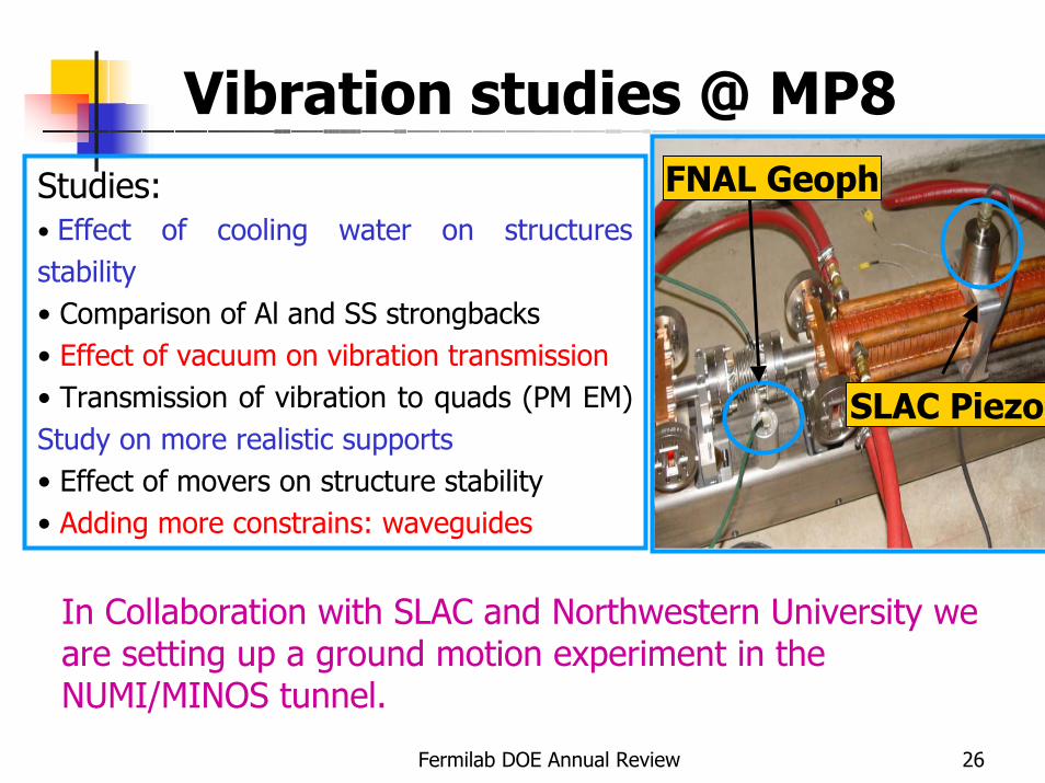
Vibration studies @ MP8Studies:• Effect of cooling water on structures stability• Comparison of Al and SS strongbacks• Effect of vacuum on vibration transmission• Transmission of vibration to quads (PM EM) Study on more realistic supports• Effect of movers on structure stability• Adding more constrains: waveguides
FNAL Geoph
SLAC Piezo
In Collaboration with SLAC and Northwestern University we are setting up a ground motion experiment in the NUMI/MINOS tunnel.
Fermilab DOE Annual Review 27
Overview of SCRF activitiesLinear Collider R&D
For TESLA we built modulators and electron guns for TTF at DESY (AD) and designed vertical test dewars and cryostatsThe A0 photo-injector at FNAL is very similar to TTF and uses TESLA acceleration cavitiesWe also are designing and building a 3.9 GHz 3rd harmonic cavity. The purpose is to diminish the beam energy spread so that the electron pulse length can be made very short via a magnetic chicane
CKMFNAL has been doing R&D to build 3.9 GHz transverse kick cavities for an experiment proposed at FNAL that needs an RF separated K beam
Proton DriverFNAL has a design study in progress for an intense Proton Sourcebased upon a 8-GeV SC linac
Fermilab DOE Annual Review 28
FNAL SCRF Technical Capabilities
Both in the FNAL Accelerator Division (AD) and Technical Division (TD) have significant design capabilities useful for SCRF work
Cryogenic Engineering and DesignEngineers with experience on big cryogenic systems (Tevatron)Designed 1.8 K cryostats for LHC IR quadropoles in TDTest them at 1.8 in FNAL Magnet Test Facility
RF Engineering and DesignRF design engineersModern FR Engineering Software and design toolsComputing equipmentImproved modeling/analysis techniques(eg working on the design of xband NLC structures and couplers)
We also have been collaborating with ANL and DESY on SRF Cavity Surface Treatment Facility and plan to expand our collaborations with other labs and universities
Fermilab DOE Annual Review 29
SCRF R&D
FNAL is currently doing some Superconducting RF R&D that can benefit to the TESLA proposal (3-d harmonic system development)TD RF group is working on SCRF R&D for two FNAL projects that build SCRF capabilities relevant to a LC if the technology decision is for a cold machine
CKM: Collaboration with BD. Goal is to provide SC RF cavities (transverse kick mode) to be used to generate a separated charged K beam for the CKM experimentA0 3rd Harmonic cavity: Goal is to provide a 3.9 GHz accelerating cavity to reduce longitudinal energy spread of high current electron pulses from the A0 photo-injector. (Note: TESLA would like us to build one of these for TTF-II also so there continues to be collaboration in this area)
Fermilab DOE Annual Review 30
SCRF R&DBuilding our capabilities for the future
Develop and build elements of a SRF module fabrication and test infrastructureDesign and build a prototype of a 3.9 GHz accelerating cavity for the Photo-Injector Test StandDevelop a microphonics compensation system
Fermilab DOE Annual Review 31
3.9 GHz accelerating cavity
• 9-cell cavity and helium tank design and fabrication
• HOM coupler design and fabrication• Cell and cavity design and prototyping
Second copper model – 2/18/04
First copper model – 5/23/03
Second copper model – 2/18/04
Fermilab DOE Annual Review 32
SCRF Module FabricationCryostat for CKM cavity testing
Automatic compensation with adaptivefeedforward control method demonstrated in a 13-cell CKM cavity at room temperature.
Fermilab DOE Annual Review 34
Cold Test of the 3.9GHz 3-cell cavity in the Vertical Cryostat
Q vs. Temperature
10
100
1000
10000
2 3 3 4 4 5 5 6
Ts/T
BSC, 3.9 GHz3 cell 3-d harm
Low He level
Q vs. E_acc.
1.E+08
1.E+09
1.E+10
0 2 4 6 8 10 12 14
Pcav calcul
P peak-up signal
E-field emission limitationGoal
Tested after 140 µm BCP, heat treatment and HPR
Fermilab DOE Annual Review 35
Surface treatment facility
Mockup @ FNAL TD MDLProcess Compartment Design
Fermilab DOE Annual Review 36
Eddy Current Scanner• IB2 temporary location
• Power hookup
• 100 psi Air line connection
• Leveling
Scanning Equipment From SNS
Fermilab DOE Annual Review 38
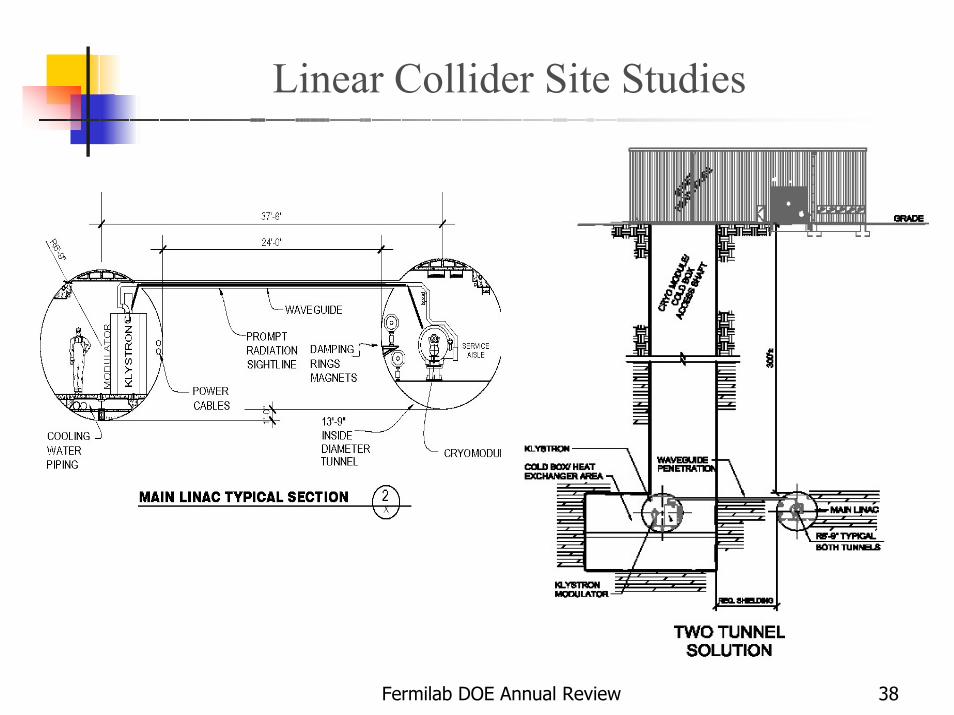
Linear Collider Site Studies
Fermilab DOE Annual Review 39
Fermilab and LC Technology Decision
• We are also developing detector collaboration with in US and except that Fermilab will play a major role in such a collaboration.
• Fermilab has considerable experience in building large detectors, Silicon, Tracking Chambers, Muon & Calorimeter.
• Computing Infrastructure and GRID
•Illinois and Fermilab is an ideal choice for the Linear Collidersite.
• We are working with local universities and ANL to bid to host Linear Collider in Illinois after the technology selection.
Fermilab DOE Annual Review 40
Summary
• Fermilab has made significant contributions to both the NLC and TESLA R&D.• Fermilab is aligning itself to be a significant player in the Linear Collider
• We will continue and expand our efforts in the accelerator, detector and IL site studies.• We are increasing our effort in the accelerator physics in MainLinac and Damping Ring.• We are proposing to build a LC ETF (warm or cold) at Fermilab to be in line with technology decision with U.S. and International linear collider collaborations.
• We are increasing Fermilab and Illinois presence within the LC collaboration(s).• We are taking an active role in US and International efforts on LC.