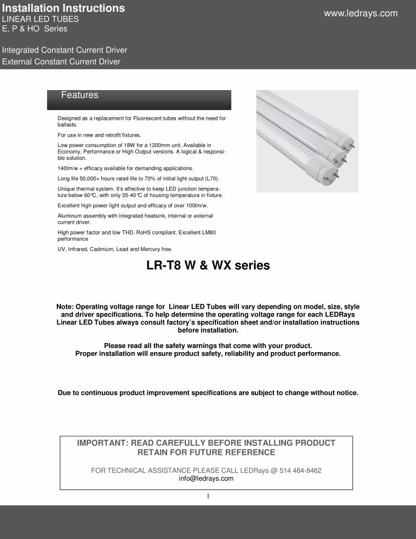
1 Installation Instructions LINEAR LED TUBES E, P & HO Series Integrated Constant Current Driver External Constant Current Driver Note: Operating voltage range for Linear LED Tubes will vary depending on model, size, style and driver specifications. To help determine the operating voltage range for each LEDRays Linear LED Tubes always consult factory’s specification sheet and/or installation instructions before installation. Please read all the safety warnings that come with your product. Proper installation will ensure product safety, reliability and product performance. Due to continuous product improvement specifications are subject to change without notice. LR-T8 W & WX series IMPORTANT: READ CAREFULLY BEFORE INSTALLING PRODUCT RETAIN FOR FUTURE REFERENCE FOR TECHNICAL ASSISTANCE PLEASE CALL LEDRays @ 514 484-8462 [email protected]www.ledrays.com Designed as a replacement for Fluorescent tubes without the need for ballasts. For use in new and retrofit fixtures. Low power consumption of 18W for a 1200mm unit. Available in Economy, Performance or High Output versions. A logical & responsi- ble solution. 140lm/w + efficacy available for demanding applications. Long life 50,000+ hours rated life to 70% of initial light output (L70). Unique thermal system. It’s effective to keep LED junction tempera- ture below 60°C, with only 35-40°C of housing temperature in fixture. Excellent high power light output and efficacy of over 100lm/w. Aluminum assembly with integrated heatsink, internal or external current driver. High power factor and low THD, RoHS compliant. Excellent LM80 performance UV, Infrared, Cadmium, Lead and Mercury free. Features
Transcript
1
Installation Instructions LINEAR LED TUBES E, P & HO Series
Integrated Constant Current Driver
External Constant Current Driver
Note: Operating voltage range for Linear LED Tubes will vary depending on model, size, style and driver specifications. To help determine the operating voltage range for each LEDRays
Linear LED Tubes always consult factory’s specification sheet and/or installation instructions before installation.
Please read all the safety warnings that come with your product.
Proper installation will ensure product safety, reliability and product performance.
Due to continuous product improvement specifications are subject to change without notice.
LR-T8 W & WX series
IMPORTANT: READ CAREFULLY BEFORE INSTALLING PRODUCT RETAIN FOR FUTURE REFERENCE
FOR TECHNICAL ASSISTANCE PLEASE CALL LEDRays @ 514 484-8462
⃞ (A) G13 Bi Pin ⃞ (B) FA8 single Pin ⃞ (C) HO RD17 ⃞ (D) Surface
⃞⃞ ⃞⃞ (B) >70 ⃞ (M) >80 ⃞ (H) >90 ⃞ (+) >90+
⃞⃞ (C) Clear ⃞ (D) Difusing ⃞ (S) Semi-difusing
Viewing
Angle
⃞ (R) 120 Deg ⃞ (W) 180 Deg
LR-T8 — — — —–
Part Numbers:
PRODUCT DIMENSIONS Linear LED Tube: (External Driver Dimensions are on page 11)
Model A B
9W 588 ± 1mm 602 ± 1mm
14W 894 ± 1mm 908 ± 1mm
15W, 18W & 22W 1198 ± 1mm 1212 ± 1mm
22W 1498 ± 1mm 1512 ± 1mm
24W 1760 ± 1mm 1774 ± 1mm
36W 2369 ± 1mm 2383 ± 1mm
LEDRAYS PART NUMBERS & PRODUCT DIMENSIONS
Installation Instructions LINEAR LED TUBES E, P & HO Series
Integrated & External Constant Current Driver
www.ledrays.com
4
♦ Verify shipped contents please do not proceed with the installation if any damage is found, please
contact LEDRAYS INC.
♦ Verify that the correct mounts, accessories, parts & hardware are available prior to commencing
work.
♦ All work should be done by a qualified electrician in accordance with the National Electrical Code,
applicable local codes and ordinances. Always check with the Authority Having Jurisdiction (AHJ)
to confirm acceptable procedures.
♦ For External Driver systems confirm the operating voltage of your system with the label on Linear
LED Tubes and driver/power supply.
♦ For Integrated Driver systems confirm the operating voltage of your system with the label on Lin-
ear LED Tubes.
♦ Do not operate in extreme heat or high humidity environments. Operating temperature range be-
tween –30°C and +45°C/-22°F and +113°F.
♦ Do not modify or operate with dimmers or other non approved control circuits unless the Linear
LED Tube is equipped with that option.
♦ Linear LED Tubes are designed to operate in a free air environment any immediate enclosed
space will reduce its lifespan and may void the warranty.
♦ Linear LED Tubes with external drivers are installed in retrofit fixtures. (Linear LED Tubes with
external drivers operate at 36 - 44VDC in constant current mode)
♦ Linear LED Tubes with both integrated or external drivers can be installed into new LEDRays LED
certified fixtures or other fixtures with an approved LED rating.
♦ Do not use in open fixtures exposed to the elements.
♦ Danger – Risk Of Shock – Disconnect Power Before Installation.
♦ Do not drop the LED tube as the connector pins may deform or break.
♦ Please use supplied original packing for protection when transporting Linear LED Tubes.Do not
operate product in packing carton.
Please observe proper precautions when removing the old fluorescent tubes. Fluorescent lamps contain mercury which is released as toxic dust and vapors. Care must be used to insure that the lamps are not broken. Proper disposal is also required for the Fluorescent tubes & ballast
please refer to the official EPA web site for instructions.
LINEAR LED TUBES & DRIVER/POWER SUPPLIES CONTAIN NO USER SERVICEABLE PARTS INSIDE AND NO FIELD REPLACEABLE PARTS.
GENERAL SAFETY INSTRUCTIONS
www.ledrays.com
Installation Instructions LINEAR LED TUBES E, P & HO Series
5
INTEGRATED DRIVER LINEAR LED TUBE WIRING
(Including U Tubes)
SAFETY INSTRUCTIONS
Danger – Risk Of Shock – Disconnect Power Before Installation. WARNING - Risk of fire or electric shock. The electrical rating of these products are 120-277Vac, the installer must determine whether they have 120-277Vac at the luminaire before installation. This product must be installed in accordance with the applicable installation code by a person familiar with the construction and operation of the product and the hazards involved. WARNING - Risk of fire or electric shock. Luminaire wiring and electrical parts may be damaged when drilling for installation of LED retrofit kit. Check for enclosed wiring and components. WARNING - THIS DEVICE IS NOT INTENDED FOR USE WITH EMERGENCY EXITS WARNING - Risk of fire or electric shock. LED Retrofit kit installation requires knowledge of luminaires electrical systems. If not qualified, do not attempt installation. Contact a qualified electrician. WARNING - Risk of fire or electric shock. Install this kit only in the luminaires that have the construction features and dimensions shown in the photographs and/or drawings. Do not make or alter any open holes in an enclosure of wiring or electrical components during kit installation. WARNING - To prevent wiring damage or abrasion, do not expose wiring to edges of sheet metal or other sharp objects. WARNING: To avoid potential fire or shock hazard, do not use this retrofit kit in luminaires employing shunted bi-pin lampholders. Note: Shunted lamp holders are found only in fluorescent luminaires with Instant-Start ballasts. Instant-start ballasts can be identified by the words “Instant Start” or “I.S.” marked on the ballast. This designation may be in the form of a statement pertaining to the ballast itself, or may be combined with the marking for the lamps with which the ballast is intended to be used, for example F40T12/IS. For more information, contact the LED luminaire retrofit kit manufacturer.
WARNING : means “DOUBLE INSULATION”
WARNING –To prevent wiring damage or abrasion, do not expose wiring to edges of sheet metal or other sharp objects. Installers should not disconnect existing wires from lampholder terminals to make new connections at lampholder terminals. Instead installers should cut existing lampholder leads away from the lampholder and make new electrical connections to lampholder lead wires by employing applicable connectors.
www.ledrays.com
Installation Instructions LINEAR LED TUBES E, P & HO Series
6
Installation Procedure Linear LED Tube: Step 1: Remove ballast and starter where applicable, and the corresponding wires including branch cir-cuit wires and ballast wires. If existing lampholder terminals are shorted by a jumper (as in instant start circuit), then remove the jumper. Step 2: According to the Schematic wiring diagram, connect the wire of L ,N in AC120~277V with either
lampholder at the end of fixture, then labeled the “Output、Input” (refer to the diagram below) order to
identify the direction for installation. Pins opposite of input end on Linear LED tube are open circuit (no connection) and used for mechanical support only. Luminaire with starter fig.1:
The original fixture and lamp holders (sockets) must be in good working condition before proceeding.
For both Integrated or External driver Linear LED Tubes require that original fixture ballast and or starter to be removed or remain in the fixture in an inoperable state (unconnected).
Please special attention to Linear LED Tube type and understand the differences between integrated and external configurations before proceeding. Differences exist in driver secondary wiring requirements within the available voltage ranges.
Do not install in a raceway or a luminaire marked for through branch wiring.
Linear LED Tubes are not intended for use with emergency exits.
Linear LED Tube are intended to retrofit Type IC or Non-IC Recessed, or surface-mounted fluorescent luminaires.
WARNING
www.ledrays.com
Installation Instructions LINEAR LED TUBES E, P & HO Series
7
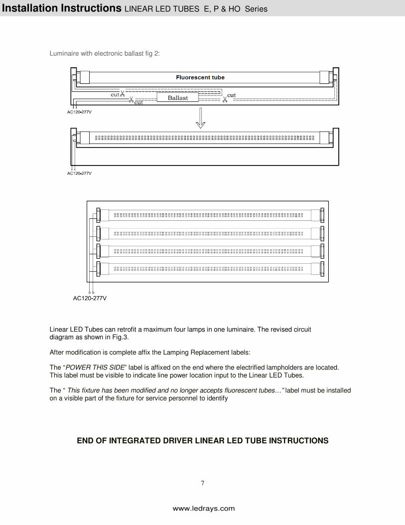
Luminaire with electronic ballast fig 2:
Linear LED Tubes can retrofit a maximum four lamps in one luminaire. The revised circuit diagram as shown in Fig.3. After modification is complete affix the Lamping Replacement labels: The “POWER THIS SIDE” label is affixed on the end where the electrified lampholders are located. This label must be visible to indicate line power location input to the Linear LED Tubes. The “ This fixture has been modified and no longer accepts fluorescent tubes…” label must be installed on a visible part of the fixture for service personnel to identify
END OF INTEGRATED DRIVER LINEAR LED TUBE INSTRUCTIONS
www.ledrays.com
Installation Instructions LINEAR LED TUBES E, P & HO Series
8
Installation Procedure U Tube: Dimensions
Step 1: Remove ballast and starter where applicable, and the corresponding wires including branch cir-cuit wires and ballast wires. If existing lampholder terminals are shorted by a jumper (as in instant start circuit), then remove the jumper. Step 2: According to the Schematic wiring diagram, connect the wire of L 、N in AC120~277V with ei-
ther lampholder at the end of fixture, then labeled the “Output、Input” (refer to the diagram below) order to identify the direction for installation. Pins opposite of input end on Linear LED tube are open circuit (no connection) and used for mechanical support only. Luminaire with starter fig.1:
www.ledrays.com
Installation Instructions LINEAR LED TUBES E, P & HO Series
9
Luminaire with electronic ballast fig 2: Linear LED Tubes can retrofit a maximum two lamps in one luminaire. The revised circuit diagram as shown in Fig.3.
The spacing between two lamps shall be minimum of 11cm/(4.33”).
After modification is complete affix the Lamping Replacement labels: The “POWER THIS SIDE” label is affixed on the end where the electrified lampholders are located. This label must be visible to indicate line power location input to the Linear LED Tubes. The “ This fixture has been modified and no longer accepts fluorescent tubes…” label must be installed on a visible part of the fixture for service personnel to identify
END INTEGRATED DRIVER U TUBE INSTRUCTIONS
www.ledrays.com
Installation Instructions LINEAR LED TUBES E, P & HO Series
10
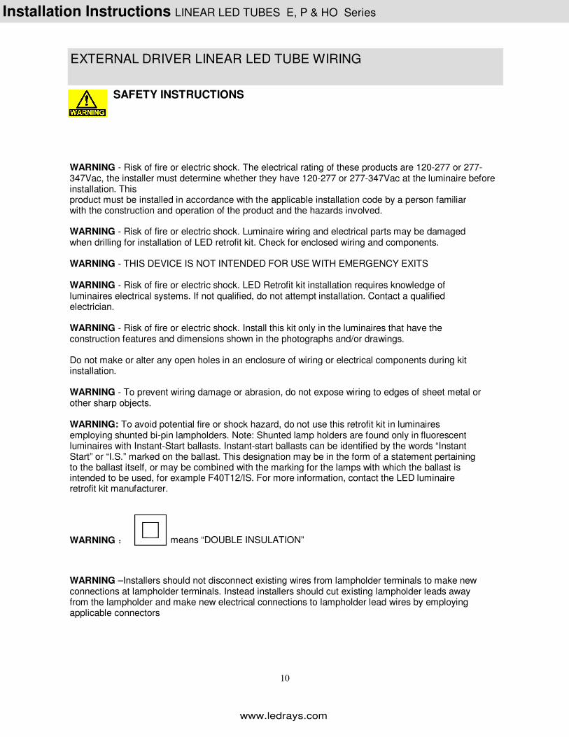
EXTERNAL DRIVER LINEAR LED TUBE WIRING
SAFETY INSTRUCTIONS
WARNING - Risk of fire or electric shock. The electrical rating of these products are 120-277 or 277-347Vac, the installer must determine whether they have 120-277 or 277-347Vac at the luminaire before installation. This product must be installed in accordance with the applicable installation code by a person familiar with the construction and operation of the product and the hazards involved. WARNING - Risk of fire or electric shock. Luminaire wiring and electrical parts may be damaged when drilling for installation of LED retrofit kit. Check for enclosed wiring and components. WARNING - THIS DEVICE IS NOT INTENDED FOR USE WITH EMERGENCY EXITS WARNING - Risk of fire or electric shock. LED Retrofit kit installation requires knowledge of luminaires electrical systems. If not qualified, do not attempt installation. Contact a qualified electrician. WARNING - Risk of fire or electric shock. Install this kit only in the luminaires that have the construction features and dimensions shown in the photographs and/or drawings. Do not make or alter any open holes in an enclosure of wiring or electrical components during kit installation. WARNING - To prevent wiring damage or abrasion, do not expose wiring to edges of sheet metal or other sharp objects. WARNING: To avoid potential fire or shock hazard, do not use this retrofit kit in luminaires employing shunted bi-pin lampholders. Note: Shunted lamp holders are found only in fluorescent luminaires with Instant-Start ballasts. Instant-start ballasts can be identified by the words “Instant Start” or “I.S.” marked on the ballast. This designation may be in the form of a statement pertaining to the ballast itself, or may be combined with the marking for the lamps with which the ballast is intended to be used, for example F40T12/IS. For more information, contact the LED luminaire retrofit kit manufacturer.
WARNING : means “DOUBLE INSULATION”
WARNING –Installers should not disconnect existing wires from lampholder terminals to make new connections at lampholder terminals. Instead installers should cut existing lampholder leads away from the lampholder and make new electrical connections to lampholder lead wires by employing applicable connectors
www.ledrays.com
Installation Instructions LINEAR LED TUBES E, P & HO Series
11
Driver Model Tube Power Configuration
PX600S 9W Single one tube/one driver
PX900S 14W Single one tube/one driver
PX1200S 15W, 18W & 22W Single one tube/one driver
PX1500S 22W Single one tube/one driver
PX1800S 24W Single one tube/one driver
PX2400S 36W Single one tube/one driver
PX1200D 2 x 18W Dual tube support
PX1200E 2 x 18W Emergency Dual tube support emergency
PX1200T 3 x 18W Triple tube support
PX1200Q 4 x 18W Quad tube support
External Driver Configurations
HV suffix after driver part number denotes AC277-347V version. Do not make or alter any open holes in an enclosure of wiring or electrical components during kit Installation.
Installation Instructions LINEAR LED TUBES E, P & HO Series
12
For Linear LED Tubes of 1500mm, 1800mm or 2400mm in length install 2 x supporting clips (supplied) equidistant to both ends. As shown below:
SIDE VIEW END VIEW
Driver wiring configurations for AC277-347V version.
Please note driver output to Linear LED Tube is single ended for this voltage version. Shorted (shunted) lampholders if present cannot be used
and must be replaced by non-shorted units) Single unit: 4 x single units into retrofit fixture:
www.ledrays.com
Installation Instructions LINEAR LED TUBES E, P & HO Series
13
Driver wiring configurations for AC100-277V version.
Please note driver output to Linear LED Tube is dual ended for this voltage version.
Step 1: Remove ballast where applicable, and the corresponding wires including branch circuit wires and ballast wires. Step 2: According to the Schematic wiring diagram the L (Black wire) & N (white wire) of LED Driver is connected to corresponding L & N of the luminaire ( L-L, N-N connections), connect the output wires of LED driver to the wire of the lampholder at both sides.
www.ledrays.com
Installation Instructions LINEAR LED TUBES E, P & HO Series
14
Luminaire with starter:
Luminaire with non-shunted electronic ballast:
Luminaire with shunted electronic ballast:
The spacing between two lamps shall be minimum of 11cm/(4.33”).
Please follow specific secondary (output) wiring for either 100-277VAC or 277-347VAC driver types.
www.ledrays.com
Installation Instructions LINEAR LED TUBES E, P & HO Series
15
Using supplied screws or related materials mount driver in correct position,( Driver should be enclosed inside the tray of ballast)
After modification of the luminaire is complete Affix the labels provided on a painted surface. This must be visible during relamping either on the ballast tray or retrofit fixture
END OF EXTERNAL DRIVER LINEAR LED TUBE INSTRUCTIONS
www.ledrays.com
Installation Instructions LINEAR LED TUBES E, P & HO Series