186
Linear Line www.MotionIndustries.com General catalogue English

Linear Line
www.MotionIndustries.com
General catalogueEnglish

When you move. We move
Rollon S.p.A. was founded in 1975 as a manufacturer of linear motion components. Today Rollon group is a
leading name in the design, production and sale of linear rails, telescopic rails and actuators, with headquar-
ters based in Italy and offi ces and distributors located throughout the world. Rollon products are used in many
industries with creative and effi cient solutions in a wide range of applications used on a daily basis.
Solutions for linear motion
Linear Rails Telescopic Rails ActuatorsRails with roller bearings
Rails with caged ball bearings
Rails with recirculating ball bearing
Rails with partial/total extension
Heavy duty rails
Rails for and automated/manual
applications
Belt driven actuators
Ball screw driven actuators
Rack and pinion actuators
Actuator Line
www.rollon.com
EN_Actuator_COVER.indd 1 08/05/2014 10:15:21
www.rollon.com
Linear Line
www.rollon.com
Sys
Prismatic Rail
www.rollon.com
Actuator Line
www.rollon.com
Hegra Rail
www.rollon.com

Aerospace
Medical Specialty Vehicles Robotics Packaging
Railway Logistics Industrial Machines
Applications
Core Competencies
Full range of linear rails, telescopic rails and actuators
Worldwide presence with branches and distributors
Fast delivery all over the world
Large technical know-how for applications
Standard solutions Collaboration CustomizationWide range of products and sizes
Linear rails with roller and caged ball
bearings
Heavy duty telescopic rails
Belt or ball screw driven linear actuators
Multi-axis systems
International know-how in several
industries
Project consultancy
Maximizing performance and cost
optimization
Special products
Research and development of new
solutions
Technologies dedicated to different
sectors
Optimal surface treatment

Content
Compact Rail
Technical features overview
1 Product explanation
Compact Rail is the product family of roller slider systems CR-2
2 Technical data Performance characteristics and notes CR-5
Confi gurations and behavior of the slider
under yawing moment Mz CR-6
Load capacities CR-8
3 Product dimensions
Rail T, U, K CR-12
Rail TR (ground custom design) CR-14
Rail length CR-15
N-version slider, normal CR-16
N-version slider, long CR-18
C-version slider CR-20
T-rail with N- / C-slider CR-24
TR-rail with N- / C-slider CR-25
U-rail with N- / C-slider CR-26
K-rail with N- / C-slider CR-27
Offset of fixing holes CR-28
4 Accessories Rollers CR-29
Wipers for C-slider, Alignment fixture AT (for T- and U-rail),
Alignment fixture AK (for K-rail) CR-30
Fixing screws CR-31
Manual clamp elements CR-32
5 Technical instructions Linear accuracy CR-33
Rigidity CR-35
Supported sides CR-39
T+U-system tolerance compensation CR-40
K+U-system tolerance compensation CR-42
Preload CR-45
Drive force CR-48
Static load CR-50
Calculation formulas CR-51
Service life calculation CR-54
Lubrication, N-slider lubrication CR-56
C-slider lubrication, Corrosion protection,
Speed and acceleration, Operating temperatures CR-57
6 Installation instructions Fixing holes CR-58
Adjusting the sliders, Use of radial ball bearing rollers CR-59
Installing the single rail CR-60
Parallel installation of two rails CR-63
Compact Rail
FrontespizioCompactrail.indd 1 07/10/2013 11:22:57

X Rail1 Product explanation X-Rail: Corrosion resistant or zinc-plated steel linear bearings XR-2
2 Technical data Performance characteristics and notes XR-4
Load capacities XR-5
3 Product dimensions
Fixed rails XR-6
Compensating rails XR-8
Mounted sliders and rails XR-10
4 Accessories Roller Pins XR-11
Fixing screws XR-12
5 Technical instructions Lubrication, T+U-System XR-13
Setting preload, Use of radial ball bearing rollers XR-15
Ordering key Ordering key with explanations XR-16
Accessories XR-17
X-Rail
FrontespizioXRai.indd 1 07/10/2013 11:30:14
Installation of the T+U- or the K+U-system CR-65
Joined Rails CR-66
Installation of joined rails CR-68
Ordering key Ordering key with explanations CR-69

Easyslide1 Product explanation
Easyslide is a linear ball rail system (with caged ball bearings for the SN series
or with recirculating ball bearings for the SNK series) with single slider
or multiple sliders. ES-2
2 Technical data Performance characteristics and notes ES-4
3 Dimensions and load capacity
SN ES-5
SN ES-9
SNK ES-10
SNK ES-11
4 Technical instructions Static load ES-12
Service life ES-14
Clearance and preload, Coefficient of friction,
Linear accuracy, Speed, Temperature ES-15
Anticorrosive protection, Lubrication SN, Lubrication SNK ES-16
Fixing screws, Installation instructions ES-17
SNK Joined Rails ES-18
Instructions for use ES-19
5 Standard configurations SN Standard configurations ES-20
Ordering key Ordering key with explanations ES-22
Easyslide
FrontespizioEasyslide.indd 1 21/05/2014 21:26:17

Mono Rail
Technical features overview
1 Product explanation
Mono Rails are profile rails for the highest degree of precision MR-2
2 Technical data Performance characteristics and notes MR-5
Mono Rail load capacities MR-6
Miniature Mono Rail load capacities MR-7
3 Product dimensions
MRS – carriage with flange MR-8
MRS…W – carriage without flange MR-9
MRT…W – carriage without flange MR-10
MRR...F – rails mounted from below MR-11
Miniature Mono Rail standard width MR-12
Miniature Mono Rail large width MR-13
4 Accessories Safety equipment and covers MR-14
Metal cover strip, Flush cap MR-16
Clamping elements MR-17
Manual clamp HK MR-18
Pneumatic clamp MK / MKS MR-19
Adapter plate MR-20
5 Technical instructions Mono Rail precision MR-21
Miniature Mono Rail precision MR-22
Mono Rail Radial clearance / preload MR-23
Miniature Mono Rail Preload MR-24
Anticorrosive protection, Mono Rail lubrication MR-25
Miniature Mono Rail lubrication MR-26
Mono Rail lubrication nipple MR-28
Friction / displacement resistance MR-29
Mono Rail loading MR-30
Miniature Mono Rail loading MR-31
Mono Rail service life MR-32
Miniature Mono Rail service life MR-34
Mono Rail
FrontespizioMonorail.indd 1 19/03/2014 15:43:06
Content

Mono Rail installation instructions MR-35
Miniature Mono Rail installation instructions MR-37
Installation examples MR-42
Ordering key Ordering key with explanations MR-43
Curviline1 Product explanation
Curviline are curvilinear rails with constant and variable radii CL-3
2 Technical data Performance characteristics and notes CL-5
3 Product dimensions
Rails with constant/variable radii with tempered raceways CL-6
Slider, Mounted sliders and rails, Load capacities CL-7
Rails with constant/variable radii in carbon steel CL-8
Slider, Mounted sliders and rails, Load capacities CL-9
Rails with constant/variable radii in stainless steel CL-10
Slider in stainless steel, Rail-slider package in stainless steel, Load capacities CL-11
4 Technical instructions Anticorrosive protection,Lubrication CL-12
Setting the preload CL-13
Ordering key Ordering key with explanations CL-14
Guides suitable for all applications
Curviline
FrontespizioCurviline.indd 1 07/10/2013 11:24:20
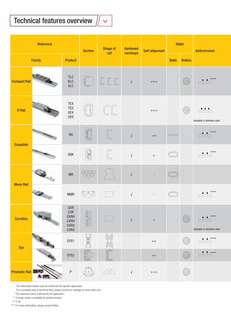
Technical features overview
Reference
SectionShape of
rail
Hardened
racewaysSelf-alignment
Slider
Anticorrosion
Family Product Balls Rollers
Mono Rail
MR √ -
MMR √ - ****
Sys
SYS1 ++ ****
SYS2 ++ ****
Prismatic Rail P √ +++
X-Rail
TEXTESUEXUES
+++
Easyslide
SN √ ++ ****
SNK √ + ****
Compact Rail
TLCKLCULC
√ +++ ****
Curviline
CKRCVR
CKRHCVRHCKRXCVRX
√ + ****
The information shown must be verifi ed for the specifi c application.
For a complete view of technical data, please consult our catalogs on www.rollon.com
* The maximum value is defi ned by the application.
** A longer stroke is available for jointed versions.
*** C 50
**** For more information, please contact Rollon.
Available in stainless steel
Available in stainless steel
COrad
My
Mzs
MzdMxCOax
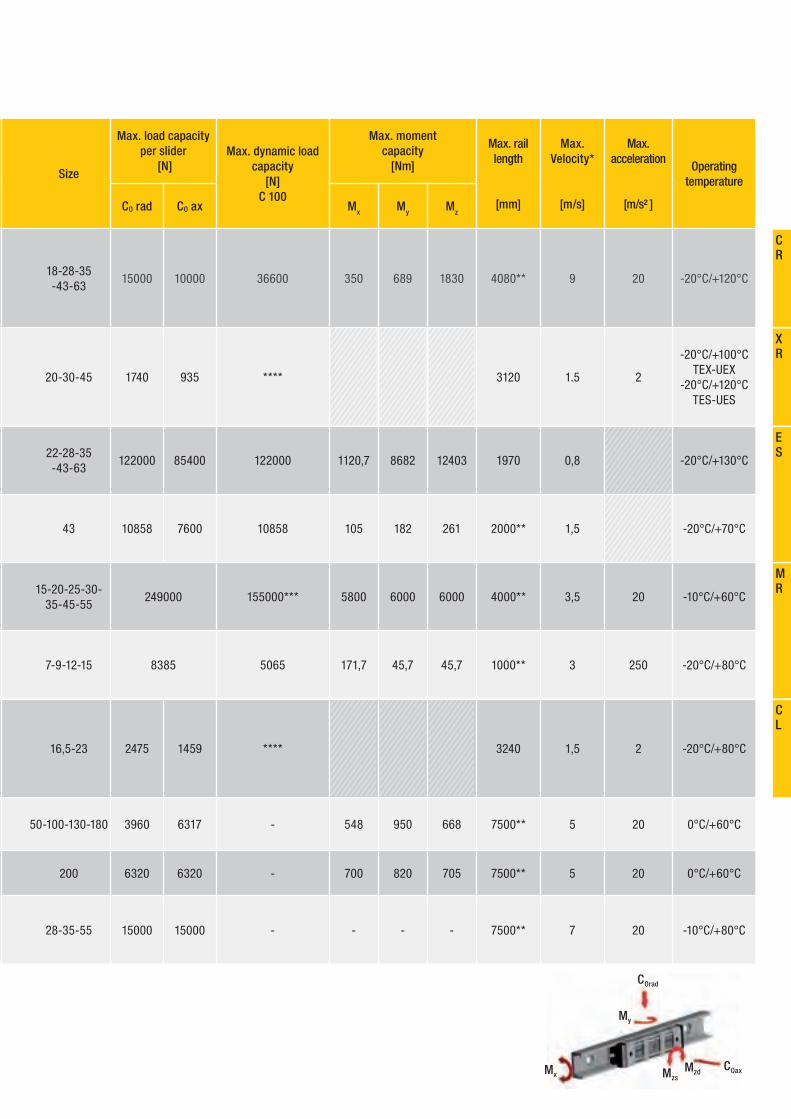
Size
Max. load capacity
per slider
[N]
Max. dynamic load
capacity
[N]
C 100
Max. moment
capacity
[Nm]
Max. rail
length
[mm]
Max.
Velocity*
[m/s]
Max.
acceleration
[m/s² ]
Operating
temperature
CO rad CO ax Mx M
yM
z
15-20-25-30-35-45-55
249000 155000*** 5800 6000 6000 4000** 3,5 20 -10°C/+60°C
7-9-12-15 8385 5065 171,7 45,7 45,7 1000** 3 250 -20°C/+80°C
50-100-130-180 3960 6317 - 548 950 668 7500** 5 20 0°C/+60°C
200 6320 6320 - 700 820 705 7500** 5 20 0°C/+60°C
28-35-55 15000 15000 - - - - 7500** 7 20 -10°C/+80°C
20-30-45 1740 935 **** 3120 1.5 2
-20°C/+100°C TEX-UEX
-20°C/+120°C TES-UES
22-28-35-43-63
122000 85400 122000 1120,7 8682 12403 1970 0,8 -20°C/+130°C
43 10858 7600 10858 105 182 261 2000** 1,5 -20°C/+70°C
18-28-35-43-63
15000 10000 36600 350 689 1830 4080** 9 20 -20°C/+120°C
16,5-23 2475 1459 **** 3240 1,5 2 -20°C/+80°C
CR
XR
ES
CL
MR
Compact Rail
FrontespizioCompactrail.indd 1 07/10/2013 11:22:57
CR-2
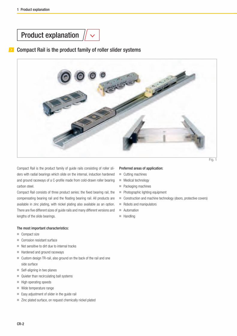
Compact Rail is the product family of roller slider systems
Compact Rail is the product family of guide rails consisting of roller sli-
ders with radial bearings which slide on the internal, induction hardened
and ground raceways of a C-profi le made from cold-drawn roller bearing
carbon steel.
Compact Rail consists of three product series: the fi xed bearing rail, the
compensating bearing rail and the fl oating bearing rail. All products are
available in zinc plating, with nickel plating also available as an option.
There are fi ve different sizes of guide rails and many different versions and
lengths of the slide bearings.
The most important characteristics:
■ Compact size
■ Corrosion resistant surface
■ Not sensitive to dirt due to internal tracks
■ Hardened and ground raceways
■ Custom design TR-rail, also ground on the back of the rail and one
side surface
■ Self-aligning in two planes
■ Quieter than recirculating ball systems
■ High operating speeds
■ Wide temperature range
■ Easy adjustment of slider in the guide rail
■ Zinc plated surface, on request chemically nickel plated
Preferred areas of application:
■ Cutting machines
■ Medical technology
■ Packaging machines
■ Photographic lighting equipment
■ Construction and machine technology (doors, protective covers)
■ Robots and manipulators
■ Automation
■ Handling
Fig. 1
Product explanation
1 Product explanation
CR-3
Compact Rail
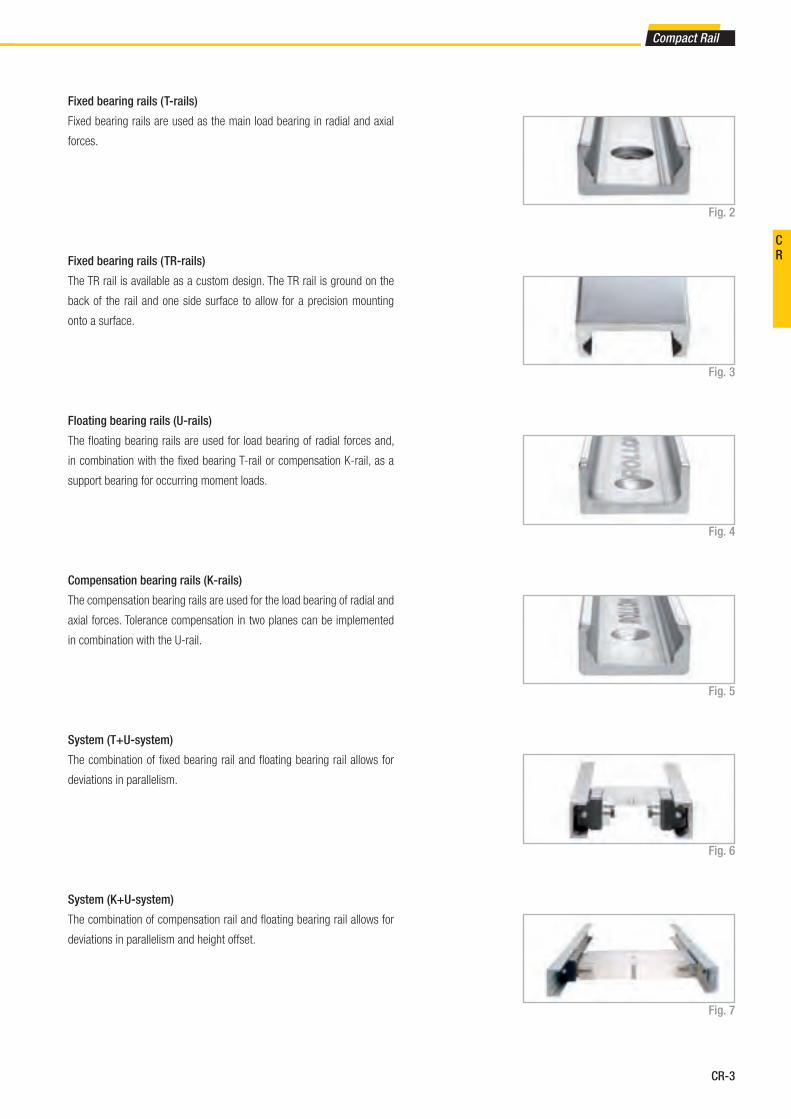
Fixed bearing rails ( T-rails)
Fixed bearing rails are used as the main load bearing in radial and axial
forces.
Compensation bearing rails (K-rails)
The compensation bearing rails are used for the load bearing of radial and
axial forces. Tolerance compensation in two planes can be implemented
in combination with the U-rail.
System (T+U-system)
The combination of fi xed bearing rail and fl oating bearing rail allows for
deviations in parallelism.
Floating bearing rails (U-rails)
The fl oating bearing rails are used for load bearing of radial forces and,
in combination with the fi xed bearing T-rail or compensation K-rail, as a
support bearing for occurring moment loads.
Fig. 2
Fig. 4
Fig. 5
Fig. 6
System (K+U-system)
The combination of compensation rail and fl oating bearing rail allows for
deviations in parallelism and height offset.
Fig. 7
Fixed bearing rails ( TR-rails)
The TR rail is available as a custom design. The TR rail is ground on the
back of the rail and one side surface to allow for a precision mounting
onto a surface.
Fig. 3
CR

CR-4
N-slider
Constructed from a, chemically nickel plated aluminum die cast body that
is available for sizes 18, 28, 43 and 63. Spring preloaded wipers and a
self-lubrication kit are integrated in the end caps (except for size 18, see
pg. 58). Confi gurable with three rollers as standard, in sizes 28 and 43.
A longer carriage with up to fi ve rollers is also available.Fig. 8
CS-slider
Constructed with zinc-plated steel body and sturdy wipers (optional) made
of polyamide. Available for all sizes. Depending on the load requirement,
slider is confi gurable with up to six rollers.
Fig. 9
Rollers
Also available individually in all sizes. Available as eccentric or concentric
rollers. Optionally available with splash-proof plastic seal (2RS) or with
steel cover disc (2Z).
Fig. 11
CD-slider
Constructed with asymmetrical zinc-plated steel body and sturdy wipers
(optional) made of polyamide. With this design it is possible to mount
your moving element to the bottom or top of the slider body. The Slider
is available for sizes 28, 35 and 43. Available with three or fi ve rollers,
depending on load case and load direction set with the corresponding
confi guration.Fig. 10
Wipers
Wipers are available for slider types CS and CD and are made of sturdy
polyamide. They keep the raceways free of contamination and thus en-
sure a longer service life.
Fig. 12
Alignment fi xture
The alignment fi xture AT / AK is used during installation of joined rails for
precise alignment of the rail transition from one to another.
Fig. 13
1 Product explanation

CR-5
Compact Rail
Slider
Rollers
Rail
Performance characteristics:
■ Available sizes for T-rail, TR-rail, U-rail: 18, 28, 35, 43, 63
■ Available sizes for K-rail: 43, 63
■ Max. operating speed: 9 m/s ( 354 in/s)
(depending on application)
■ Max. acceleration: 20 m/s2 ( 787 in/s2 )
(depending on application)
■ Max. radial load capacity: 15,000 N ( per slider)
■ Temperature range: -20 °C to +120 °C (-4 °F to +248 °F )
briefl y up to max. +170 °C (+338 °F )
■ Available rail lengths from 160 mm to 3,600 mm (6.3 in to 142 in)
in 80-mm increments (3.15 in),
longer single rails up to max. 4,080 mm (160.6 in) on request
■ Roller pins lubricated for life
■ Roller seal/shield: 2RS (splash-proof ), 2Z ( steel cover disk )
■ Roller material: steel 100Cr6
■ Rail raceways are induction hardened and ground
■ Rails and slider bodies are standard zinc-plated according to
ISO 2081
■ Rail material of T- and U-rails in sizes 18:
cold-drawn roller bearing carbon steel C43 F
■ Rail material of K-rails, as well as T- and U-rails in size 28 to 63:
CF53
Notes:
■ The sliders are equipped with rollers that are in alternating contact
with both sides of the raceway. Markings on the body around the
roller pins indicate correct arrangement of the rollers to the external
load
■ With a simple adjustment of the eccentric rollers, the desired clea-
rance or preload on the rail and slider can be set.
■ Rails in joined design are available for longer transverse distances
(see pg. CR-64)
■ The K rails are not suitable for vertical installation
■ Screws of property class 10.9 must be used
■ Differences in screw sizes must be observed
■ When mounting the rails, it is crucial to ensure that the mounting
holes in the structure are properly chamfered. (see pg. CR-58, tab.
41)
■ The general illustrations show N-sliders as an example
Fig. 14
Technical data
CR
CR-6
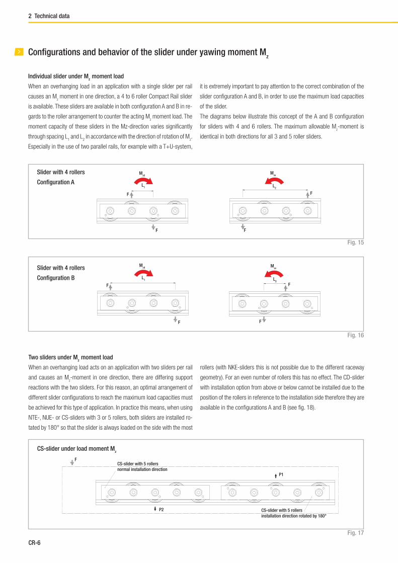
Confi gurations and behavior of the slider under yawing moment Mz
When an overhanging load in an application with a single slider per rail
causes an Mz moment in one direction, a 4 to 6 roller Compact Rail slider
is available. These sliders are available in both confi guration A and B in re-
gards to the roller arrangement to counter the acting Mz moment load. The
moment capacity of these sliders in the Mz-direction varies signifi cantly
through spacing L1 and L
2 in accordance with the direction of rotation of M
z.
Especially in the use of two parallel rails, for example with a T+U-system,
it is extremely important to pay attention to the correct combination of the
slider confi guration A and B, in order to use the maximum load capacities
of the slider.
The diagrams below illustrate this concept of the A and B confi guration
for sliders with 4 and 6 rollers. The maximum allowable Mz-moment is
identical in both directions for all 3 and 5 roller sliders.
Fig. 15
Slider with 4 rollers
Confi guration A
Slider with 4 rollers
Confi guration B
Fig. 16
Individual slider under Mz
moment load
F
F
Mzs
L2
Mzd
F
F
L1
Mzs
F
F
L2
Mzd
F
F
L1
Two sliders under Mz
moment load
When an overhanging load acts on an application with two sliders per rail
and causes an Mz-moment in one direction, there are differing support
reactions with the two sliders. For this reason, an optimal arrangement of
different slider confi gurations to reach the maximum load capacities must
be achieved for this type of application. In practice this means, when using
NTE-, NUE- or CS-sliders with 3 or 5 rollers, both sliders are installed ro-
tated by 180° so that the slider is always loaded on the side with the most
rollers (with NKE-sliders this is not possible due to the different raceway
geometry). For an even number of rollers this has no effect. The CD-slider
with installation option from above or below cannot be installed due to the
position of the rollers in reference to the installation side therefore they are
available in the confi gurations A and B (see fi g. 18).
Fig. 17
F
P2
P1
CS-slider with 5 rollers
normal installation direction
CS-slider with 5 rollers
installation direction rotated by 180°
CS-slider under load moment Mz
2 Technical data

CR-7
Compact Rail
Fig. 18
CD-slider under load moment Mz
F
P2
P1CDW43-120 P1
Confi guration A
CDW43-120
Confi guration B
Arrangement DS
This is the recommended arrangement for use of two sliders under Mz-
moment when using one rail. Also see previous page: Two sliders under
Mz moment load.
Fig. 19
Arrangement DD
For using a pair of guide rails with two sliders each under Mz moment load,
the second system should be designed in arrangement DD. This results in
the following combination: One guide rail with two sliders in arrangement
DS and the other guide rail with 2 sliders in arrangement DD. This allows
even load and moment distribution between the two parallel rails.
Fig. 20
Arrangement DA
Standard arrangement if no other information is given. This arrangement
is recommended if the load point is located within the two outside points
of the sliders.
Fig. 21
Slider confi gurations for various load cases
CR
CR-8
Slider
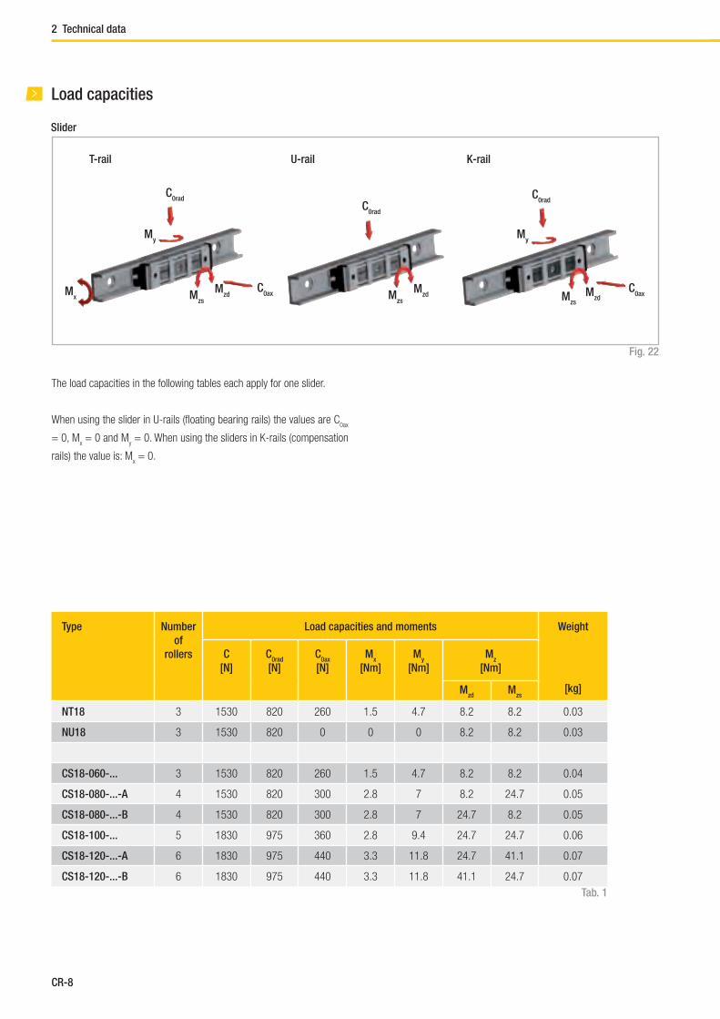
Load capacities
Fig. 22
C0rad
C0ax
T-rail U-rail K-rail
The load capacities in the following tables each apply for one slider.
When using the slider in U-rails (fl oating bearing rails) the values are C0ax
= 0, Mx = 0 and M
y = 0. When using the sliders in K-rails (compensation
rails) the value is: Mx = 0.
Type Number
of
rollers
Load capacities and moments Weight
[kg]
C
[N]
C0rad
[N]
C0ax
[N]
Mx
[Nm]
My
[Nm]
Mz
[Nm]
Mzd
Mzs
NT18 3 1530 820 260 1.5 4.7 8.2 8.2 0.03
NU18 3 1530 820 0 0 0 8.2 8.2 0.03
CS18-060-... 3 1530 820 260 1.5 4.7 8.2 8.2 0.04
CS18-080-...-A 4 1530 820 300 2.8 7 8.2 24.7 0.05
CS18-080-...-B 4 1530 820 300 2.8 7 24.7 8.2 0.05
CS18-100-... 5 1830 975 360 2.8 9.4 24.7 24.7 0.06
CS18-120-...-A 6 1830 975 440 3.3 11.8 24.7 41.1 0.07
CS18-120-...-B 6 1830 975 440 3.3 11.8 41.1 24.7 0.07
Tab. 1
My
Mx M
zs
Mzd
C0rad
Mzs
Mzd
C0rad
Mzs
Mzd
C0ax
My
2 Technical data

CR-9
Compact Rail
Type Number
of
rollers
Load capacities and moments Weight
[kg]
C
[N]
C0rad
[N]
C0ax
[N]
Mx
[Nm]
My
[Nm]
Mz
[Nm]
Mzd
Mzs
NTE28 3 4260 2170 640 6.2 16 27.2 27.2 0.115
NUE28 3 4260 2170 0 0 0 27.2 27.2 0.115
NTE28L-3-A 3 4260 2170 640 6.2 29 54.4 54.4 0.141
NTE28L-4-A 4 4260 2170 750 11.5 29 54.4 108.5 0.164
NTE28L-4-B 4 4260 2170 750 11.5 29 108.5 54.4 0.164
NTE28L-4-C 4 4260 2170 750 11.5 29 81.7 81.7 0.164
NTE28L-5-A 5 5065 2580 900 11.5 29 81.7 81.7 0.185
NTE28L-5-B 5 6816 3472 640 6.2 29 54.4 54.4 0.185
NUE28L-3-A 3 4260 2170 0 0 0 54.4 54.4 0.141
NUE28L-4-A 4 4260 2170 0 0 0 54.4 108.5 0.164
NUE28L-4-B 4 4260 2170 0 0 0 108.5 54.4 0.164
NUE28L-4-C 4 4260 2170 0 0 0 81.7 81.7 0.164
NUE28L-5-A 5 5065 2580 0 0 0 81.7 81.7 0.185
NUE28L-5-B 5 6816 3472 0 0 0 54.4 54.4 0.185
CS28-080-... 3 4260 2170 640 6.2 16 27.2 27.2 0.155
CS28-100-...-A 4 4260 2170 750 11.5 21.7 27.2 81.7 0.195
CS28-100-...-B 4 4260 2170 750 11.5 21.7 81.7 27.2 0.195
CS28-125-... 5 5065 2580 900 11.5 29 81.7 81.7 0.24
CS28-150-...-A 6 5065 2580 1070 13.7 36.2 81.7 136.1 0.29
CS28-150-...-B 6 5065 2580 1070 13.7 36.2 136.1 81.7 0.29
CD28-080-... 3 4260 2170 640 6.2 16 27.2 27.2 0.215
CD28-125-... 5 5065 2580 900 11.5 29 81.7 81.7 0.3
CS35-100-... 3 8040 3510 1060 12.9 33.7 61.5 61.5 0.27
CS35-120-...-A 4 8040 3510 1220 23.9 43.3 52.7 158.1 0.33
CS35-120-...-B 4 8040 3510 1220 23.9 43.3 158.1 52.7 0.33
CS35-150-... 5 9565 4180 1460 23.9 57.7 158.1 158.1 0.41
CS35-180-...-A 6 9565 4180 1780 28.5 72.2 158.1 263.4 0.49
CS35-180-...-B 6 9565 4180 1780 28.5 72.2 263.4 158.1 0.49
CD35-100-... 3 8040 3510 1060 12.9 33.7 61.5 61.5 0.39
CD35-150-... 5 9565 4180 1460 23.9 57.7 158.1 158.1 0.58
Tab. 2
CR

CR-10
Type Number
of
rollers
Load capacities and moments Weight
[kg]
C
[N]
C0rad
[N]
C0ax
[N]
Mx
[Nm]
My
[Nm]
Mz
[Nm]
Mzd
Mzs
NTE43 3 12280 5500 1570 23.6 60 104.5 104.5 0.385
NUE43 3 12280 5500 0 0 0 104.5 104.5 0.385
NKE43 3 12280 5100 1320 0 50.4 96.9 96.9 0.385
NTE43L-3-A 3 12280 5500 1570 23.6 108.6 209 209 0.45
NTE43L-4-A 4 12280 5500 1855 43.6 108.6 209 418 0.52
NTE43L-4-B 4 12280 5500 1855 43.6 108.6 418 209 0.52
NTE43L-4-C 4 12280 5500 1855 43.6 108.6 313.5 313.5 0.52
NTE43L-5-A 5 14675 6540 2215 43.6 108.6 313.5 313.5 0.59
NTE43L-5-B 5 19650 8800 1570 23.6 108.6 209 209 0.59
NUE43L-3-A 3 12280 5500 0 0 0 209 209 0.45
NUE43L-4-A 4 12280 5500 0 0 0 209 418 0.52
NUE43L-4-B 4 12280 5500 0 0 0 418 209 0.52
NUE43L-4-C 4 12280 5500 0 0 0 313.5 313.5 0.52
NUE43L-5-A 5 14675 6540 0 0 0 313.5 313.5 0,59
NUE43L-5-B 5 19650 8800 0 0 0 209 209 0.59
NKE43L-3-A 3 12280 5100 1320 0 97.7 188.7 188.7 0.45
NKE43L-4-A 4 12280 5100 1320 0 97.7 188.7 377.3 0.52
NKE43L-4-B 4 12280 5100 1320 0 97.7 377.3 188.7 0.52
NKE43L-4-C 4 12280 5100 1320 0 97.7 283 283 0.52
NKE43L-5-A 5 14675 6065 1570 0 97.7 283 283 0.59
NKE43L-5-B 5 19650 8160 1820 0 97.7 188.7 188.7 0.59
CS43-120-... 3 12280 5500 1570 23.6 60 104.5 104.5 0.53
CS43-150-...-A 4 12280 5500 1855 43.6 81.5 104.5 313.5 0.68
CS43-150-...-B 4 12280 5500 1855 43.6 81.5 313.5 104.5 0.68
CS43-190-... 5 14675 6540 2215 43.6 108.6 313.5 313.5 0.84
CS43-230-...-A 6 14675 6540 2645 52 135.8 313.5 522.5 1.01
CS43-230-...-B 6 14675 6540 2645 52 135.8 522.5 313.5 1.01
Tab. 3
2 Technical data
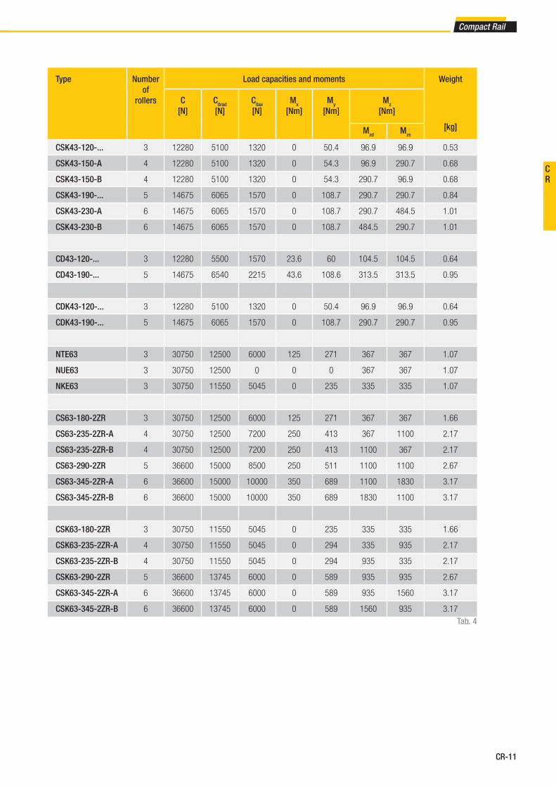
CR-11
Compact Rail
Type Number
of
rollers
Load capacities and moments Weight
[kg]
C
[N]
C0rad
[N]
C0ax
[N]
Mx
[Nm]
My
[Nm]
Mz
[Nm]
Mzd
Mzs
CSK43-120-... 3 12280 5100 1320 0 50.4 96.9 96.9 0.53
CSK43-150-A 4 12280 5100 1320 0 54.3 96.9 290.7 0.68
CSK43-150-B 4 12280 5100 1320 0 54.3 290.7 96.9 0.68
CSK43-190-... 5 14675 6065 1570 0 108.7 290.7 290.7 0.84
CSK43-230-A 6 14675 6065 1570 0 108.7 290.7 484.5 1.01
CSK43-230-B 6 14675 6065 1570 0 108.7 484.5 290.7 1.01
CD43-120-... 3 12280 5500 1570 23.6 60 104.5 104.5 0.64
CD43-190-... 5 14675 6540 2215 43.6 108.6 313.5 313.5 0.95
CDK43-120-... 3 12280 5100 1320 0 50.4 96.9 96.9 0.64
CDK43-190-... 5 14675 6065 1570 0 108.7 290.7 290.7 0.95
NTE63 3 30750 12500 6000 125 271 367 367 1.07
NUE63 3 30750 12500 0 0 0 367 367 1.07
NKE63 3 30750 11550 5045 0 235 335 335 1.07
CS63-180-2ZR 3 30750 12500 6000 125 271 367 367 1.66
CS63-235-2ZR-A 4 30750 12500 7200 250 413 367 1100 2.17
CS63-235-2ZR-B 4 30750 12500 7200 250 413 1100 367 2.17
CS63-290-2ZR 5 36600 15000 8500 250 511 1100 1100 2.67
CS63-345-2ZR-A 6 36600 15000 10000 350 689 1100 1830 3.17
CS63-345-2ZR-B 6 36600 15000 10000 350 689 1830 1100 3.17
CSK63-180-2ZR 3 30750 11550 5045 0 235 335 335 1.66
CSK63-235-2ZR-A 4 30750 11550 5045 0 294 335 935 2.17
CSK63-235-2ZR-B 4 30750 11550 5045 0 294 935 335 2.17
CSK63-290-2ZR 5 36600 13745 6000 0 589 935 935 2.67
CSK63-345-2ZR-A 6 36600 13745 6000 0 589 935 1560 3.17
CSK63-345-2ZR-B 6 36600 13745 6000 0 589 1560 935 3.17
Tab. 4
CR
CR-12
B
T
A
E2
B
A
T
E2
B
T
A
E2
B
T
A
E1
B
T
A
E1
B
A
TE1
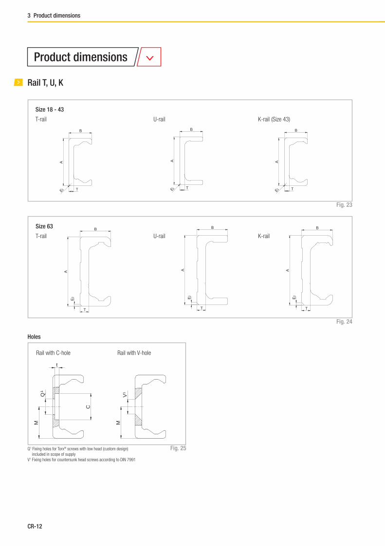
Rail T, U, K
T-rail U-rail K-rail (Size 43)
Size 18 - 43
Fig. 23
T-rail U-rail K-rail
Q1 Fixing holes for Torx® screws with low head (custom design)
included in scope of supply
V1 Fixing holes for countersunk head screws according to DIN 7991
Size 63
Fig. 24
Holes
Fig. 25
Rail with C-hole Rail with V-hole
C
Q¹
t
M MV
¹
Product dimensions
3 Product dimensions

CR-13
Compact Rail
Type Size A
[mm]
B
[mm]
M
[mm]
E1
[mm]
T
[mm]
C
[mm]
Weight
[kg/m]
E2
[°]
t
[mm]
Q1
[mm]
V1
[mm]
TLC
TLV
18 18 8.25 9 1.5 2.8 9.5 0.55 - 2 M4 M4
28 28 12.25 14 1 3 11 1.0 - 2 M5 M5
35 35 16 17.5 2 3.5 14.5 1.65 - 2.7 M6 M6
43 43 21 21.5 2.5 4.5 18 2.6 - 3.1 M8 M8
63 63 28 31.5 - 8 15 6.0 2x45 5.2 M8 M10
ULC
ULV
18 18 8.25 9 1 2.6 9,5 0.55 - 1.9 M4 M4
28 28 12 14 1 3 11 1.0 - 2 M5 M5
35 35 16 17.5 1 3.5 14.5 1.65 - 2.7 M6 M6
43 43 21 21.5 1 4.5 18 2.6 - 3.1 M8 M8
63 63 28 31.5 - 8 15 6.0 2x45 5.2 M8 M10
KLC
KLV
43 43 21 21.5 2.5 4.5 18 2.6 - 3.1 M8 M8
63 63 28 31.5 - 8 15 6.0 2x45 5.2 M8 M10
Tab. 5
CR

CR-14
B
T
A
E2
C
Q¹
t
M
B
T
A
E1
Fig. 26
Type Size A
[mm]
B
[mm]
M
[mm]
E1
[mm]
T
[mm]
C
[mm]
Weight
[kg/m]
E2
[°]
t
[mm]
Q1
[mm]
TRC
18 17.95 8 8.95 1.5 2.8 9.5 0.55 - 2 M4
28 27.83 12.15 13.83 1 2.9 11 1.0 - 2 M5
35 34.8 15.9 17.3 2 3.4 14.5 1.6 - 2.7 M6
43 42.75 20.9 21.25 2.5 4.4 18 2.6 - 3.1 M8
63 62.8 27.9 31.3 - 7.9 15 6.0 2x45 5.2 M8
Tab. 6
Rail TR (ground custom design)
T-rail
Size 18 - 43
T-rail
Size 63 Fixing Hole
Q1 Fixing holes for Torx® screws with low head (custom design) included in scope of supply
3 Product dimensions
CR-15
Compact Rail
40 -2+1
80 40
L
Reference line
+ 2 - 4
0,2
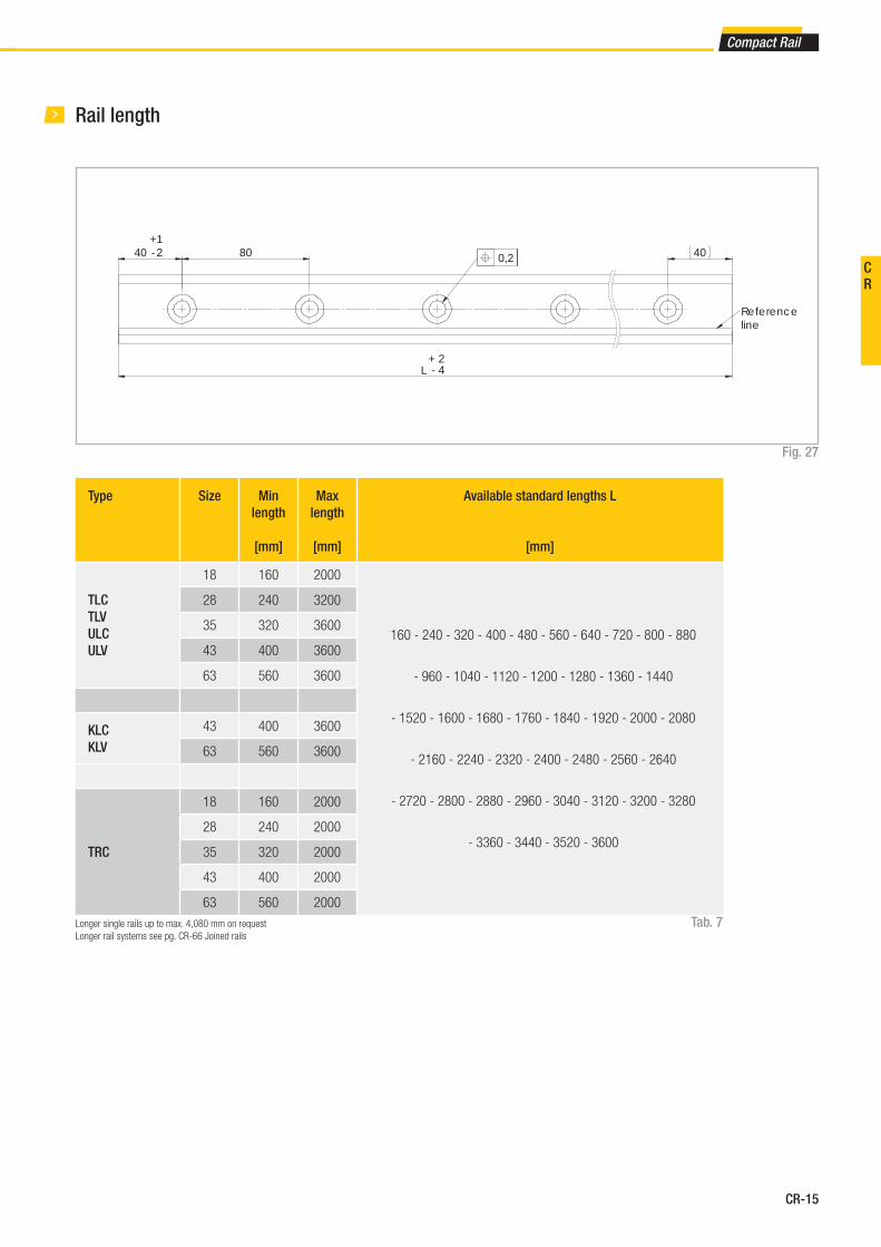
Fig. 27
Rail length
Tab. 7
Type Size Min
length
[mm]
Max
length
[mm]
Available standard lengths L
[mm]
TLC
TLV
ULC
ULV
18 160 2000
160 - 240 - 320 - 400 - 480 - 560 - 640 - 720 - 800 - 880
- 960 - 1040 - 1120 - 1200 - 1280 - 1360 - 1440
- 1520 - 1600 - 1680 - 1760 - 1840 - 1920 - 2000 - 2080
- 2160 - 2240 - 2320 - 2400 - 2480 - 2560 - 2640
- 2720 - 2800 - 2880 - 2960 - 3040 - 3120 - 3200 - 3280
- 3360 - 3440 - 3520 - 3600
28 240 3200
35 320 3600
43 400 3600
63 560 3600
KLC
KLV
43 400 3600
63 560 3600
TRC
18 160 2000
28 240 2000
35 320 2000
43 400 2000
63 560 2000
Longer single rails up to max. 4,080 mm on request
Longer rail systems see pg. CR-66 Joined rails
CR
CR-16
X
A
B
X
Y
1
F
G
C
G
F C
G
F C
X
A
B
Y
C
F
G
C
F
G
C
F
G
X
A
B
Y G
C
F F
C
G
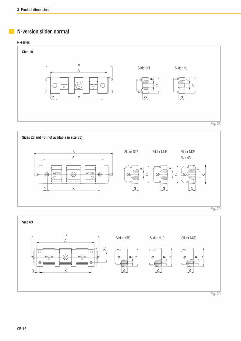
N-version slider, normal
N-series
Fig. 28
Size 18
Fig. 29
Sizes 28 and 43 (not available in size 35)
Fig. 30
Size 63
Slider NT Slider NU
Slider NTE Slider NUE Slider NKE
Size 43
Slider NTE Slider NUE Slider NKE
3 Product dimensions

CR-17
Compact Rail
Type Size A
[mm]
B
[mm]
C
[mm]
G
[mm]
F
[mm]
X
[mm]
Y
[mm]
X1
[mm]
No. of
holes
Roller type used* Number of
Rollers
NT
NU18 62 74 17.6 6.4 M5 52 5 - 2 CPA18-CPN18 3
NTE
NUE28 88 124 26,5 9.3 M5 78 5 - 2 CPA28-CPN28 3
NTE
NUE43 134 170 40 13.7 M8 114 10 - 2 CPA43-CPN43 3
NKE 43 134 170 40 13.7 M8 114 10 - 2 CRA43-CRN43 3
NTE
NUE63 188 225 60 20.2 M8 168 10 34 4 CPA63-CPN63 3
NKE 63 188 225 60 20.2 M8 168 10 34 4 CRA63-CRN63 3
Tab. 8* Information about the roller type, see pg. CR-29, tab. 18
CR

CR-18
B
A
Y X Z X
F
C
G
F
C
G
F
C
G
N...L-series
Fig. 31
Sizes 28 and 43
Slider confi gurations N...L
Fig. 32
N-version slider, long
Slider NTE Slider NUE Slider NKE
Size 43
N...L-3-A
N...L-4-A
N...L-4-B
N...L-4-C
N...L-5-A
N...L-5-B
3 Product dimensions

CR-19
Compact Rail
Type Size A
[mm]
B
[mm]
C
[mm]
G
[mm]
F
[mm]
X
[mm]
Y
[mm]
Z
[mm]
No. of
holes
Roller type
used*
Number**
of Rollers
NTE28L
NUE28L28 140 176 26.5 9 M5 52 5 26 4 CPA28
3
4
5
NTE43L
NUE43L 43 208 245 41 13.7 M8 75.5 10 37 4CPA43 3
4
5NKE43L CRA43
Tab. 9* Information about the roller type, see pg. CR-29, tab. 18
** The number of roller varies according to the confi guration, see pg. CR-18, fi g. 32
CR

CR-20
F
C
G
C
F
G
BA
Y X X
BA
Y X X
BA
Y X X X
BA
Y X
BA
Y X
BA
Y X
CS-series
Fig. 33
Fig. 34
C-version slider
CS-slider with prismatic rollers for use
in T- and U-rails
Representation of slider with wiper
CSK-slider with crowned rollers for
use in K-rails
Sizes 43 and 63
Confi guration A Confi guration A
Confi guration B Confi guration B
3 Product dimensions

CR-21
Compact Rail
Type Size A
[mm]
B
[mm]
C
[mm]
G
[mm]
F
[mm]
X
[mm]
Y
[mm]
No. of
holes
Roller type
used*
Number of
Rollers
CS
18
60 76 9.5 5.7 M5 20 20 2 CPA18-CPN18 3
80 96 9.5 5.7 M5 40 20 2 CPA18 4
100 116 9.5 5.7 M5 20 20 4 CPA18 5
120 136 9.5 5.7 M5 40 20 3 CPA18 6
28
80 100 14.9 9.7 M5 35 22.5 2 CPA28-CPN28 3
100 120 14.9 9.7 M5 50 25 2 CPA28 4
125 145 14.9 9.7 M5 25 25 4 CPA28 5
150 170 14.9 9.7 M5 50 25 3 CPA28 6
35
100 120 19.9 11.9 M6 45 27.5 2 CPA35-CPN35 3
120 140 19.9 11.9 M6 60 30 2 CPA35 4
150 170 19.9 11.9 M6 30 30 4 CPA35 5
180 200 19.9 11.9 M6 60 30 3 CPA35 6
43
120 140 24.9 14.5 M8 55 32.5 2 CPA43-CPN43 3
150 170 24.9 14.5 M8 80 35 2 CPA43 4
190 210 24.9 14.5 M8 40 35 4 CPA43 5
230 250 24.9 14.5 M8 80 35 3 CPA43 6
63
180 200 39.5 19.5 M8 54 9 4 CPA63 3
235 255 39.5 19.5 M8 54 9.5 5 CPA63 4
290 310 39.5 19.5 M8 54 10 6 CPA63 5
345 365 39.5 19.5 M8 54 10.5 7 CPA63 6
CSK
43
120 140 24.9 14.5 M8 55 32.5 2 CRA43-CRN43 3
150 170 24.9 14.5 M8 80 35 2 CRA43 4
190 210 24.9 14.5 M8 40 35 4 CRA43 5
230 250 24.9 14.5 M8 80 35 3 CRA43 6
63
180 200 39.5 19.5 M8 54 9 4 CRA63 3
235 255 39.5 19.5 M8 54 9.5 5 CRA63 4
290 310 39.5 19.5 M8 54 10 6 CRA63 5
345 365 39.5 19.5 M8 54 10.5 7 CRA63 6
Tab. 10* Information about the roller type, see pg. CR-29, tab. 18
CR
CR-22
AB
Y X X X
AB
Y X X X
AB
Y X
AB
Y X
T
C
G
F
MHole S for screw according to DIN 912
T
C
F
G
MHole S for screw according to DIN 912
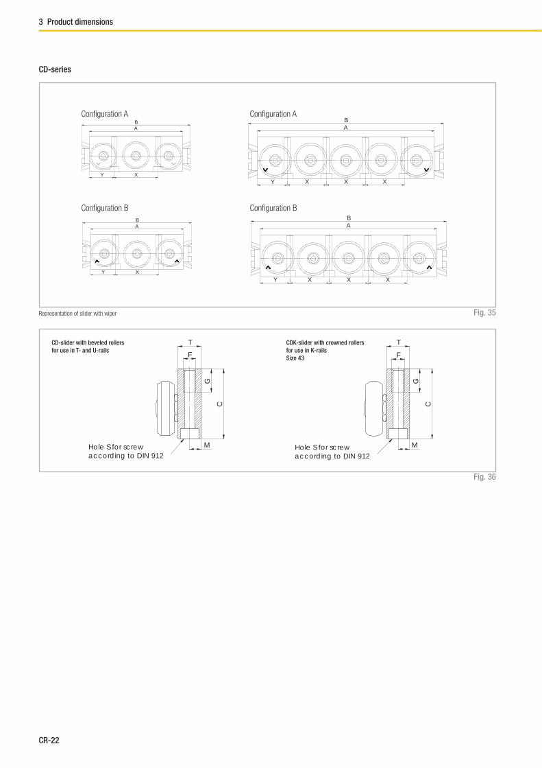
CD-series
Fig. 35
Confi guration A Confi guration A
Confi guration B Confi guration B
Representation of slider with wiper
Fig. 36
CD-slider with beveled rollers
for use in T- and U-rails
CDK-slider with crowned rollers
for use in K-rails
Size 43
3 Product dimensions

CR-23
Compact Rail
Type Size A
[mm]
B
[mm]
C
[mm]
T
[mm]
M
[mm]
S G
[mm]
F X
[mm]
Y
[mm]
No. of
holes
Roller type
used*
Number of
Rollers
CD
2880 100 29.9 9.9 4.9 M5 15 M6 36 22 2 CPA28 3
125 145 29.9 9.9 4.9 M5 15 M6 27 22 4 CPA28 5
35100 120 34.9 11.8 5.9 M6 15 M8 45 27.5 2 CPA35 3
150 170 34.9 11.8 5.9 M6 15 M8 30 30 4 CPA35 5
43120 140 44.9 14.8 7.3 M6 15 M8 56 32 2 CPA43 3
190 210 44.9 14.8 7.3 M6 15 M8 42 32 4 CPA43 5
CDK 43120 140 44.9 14.8 7.3 M6 15 M8 56 32 2 CRA43 3
190 210 44.9 14.8 7.3 M6 15 M8 42 32 4 CRA43 5
Tab. 11* Information about the roller type, see pg. CR-29, tab. 18
CR
CR-24
A
C D
BReference line
A C
D
BReference line
A C D
BReference line
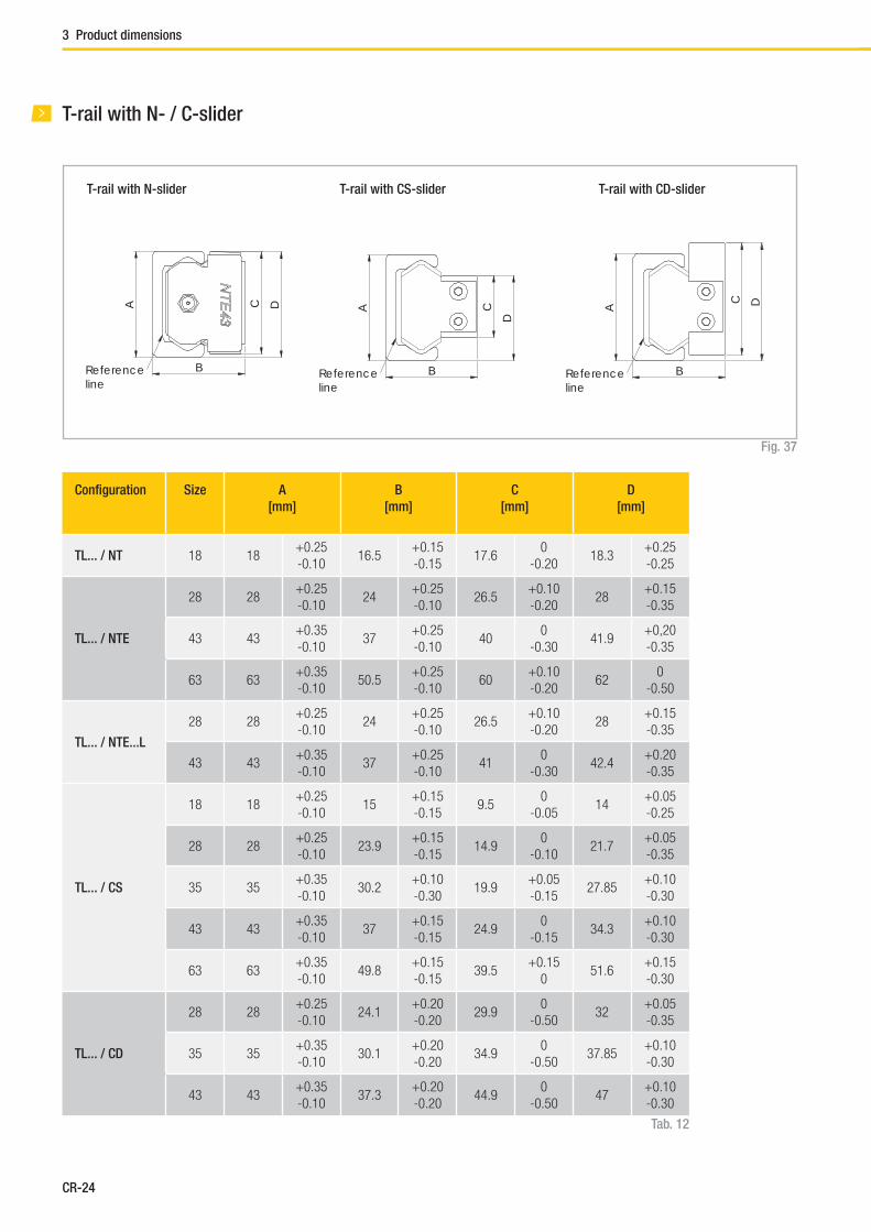
T-rail with N- / C-slider
T-rail with CS-sliderT-rail with N-slider
Fig. 37
Confi guration Size A
[mm]
B
[mm]
C
[mm]
D
[mm]
TL... / NT 18 18+0.25
-0.1016.5
+0.15
-0.1517.6
0
-0.2018.3
+0.25
-0.25
TL... / NTE
28 28+0.25
-0.1024
+0.25
-0.1026.5
+0.10
-0.2028
+0.15
-0.35
43 43+0.35
-0.1037
+0.25
-0.1040
0
-0.3041.9
+0,20
-0.35
63 63+0.35
-0.1050.5
+0.25
-0.1060
+0.10
-0.2062
0
-0.50
TL... / NTE...L
28 28+0.25
-0.1024
+0.25
-0.1026.5
+0.10
-0.2028
+0.15
-0.35
43 43+0.35
-0.1037
+0.25
-0.1041
0
-0.3042.4
+0.20
-0.35
TL... / CS
18 18+0.25
-0.1015
+0.15
-0.159.5
0
-0.0514
+0.05
-0.25
28 28+0.25
-0.1023.9
+0.15
-0.1514.9
0
-0.1021.7
+0.05
-0.35
35 35+0.35
-0.1030.2
+0.10
-0.3019.9
+0.05
-0.1527.85
+0.10
-0.30
43 43+0.35
-0.1037
+0.15
-0.1524.9
0
-0.1534.3
+0.10
-0.30
63 63+0.35
-0.1049.8
+0.15
-0.1539.5
+0.15
051.6
+0.15
-0.30
TL... / CD
28 28+0.25
-0.1024.1
+0.20
-0.2029.9
0
-0.5032
+0.05
-0.35
35 35+0.35
-0.1030.1
+0.20
-0.2034.9
0
-0.5037.85
+0.10
-0.30
43 43+0.35
-0.1037.3
+0.20
-0.2044.9
0
-0.5047
+0.10
-0.30
Tab. 12
T-rail with CD-slider
3 Product dimensions
CR-25
Compact Rail
A C D
BReference line
A
C D
BReference line
A C
D
BReference line
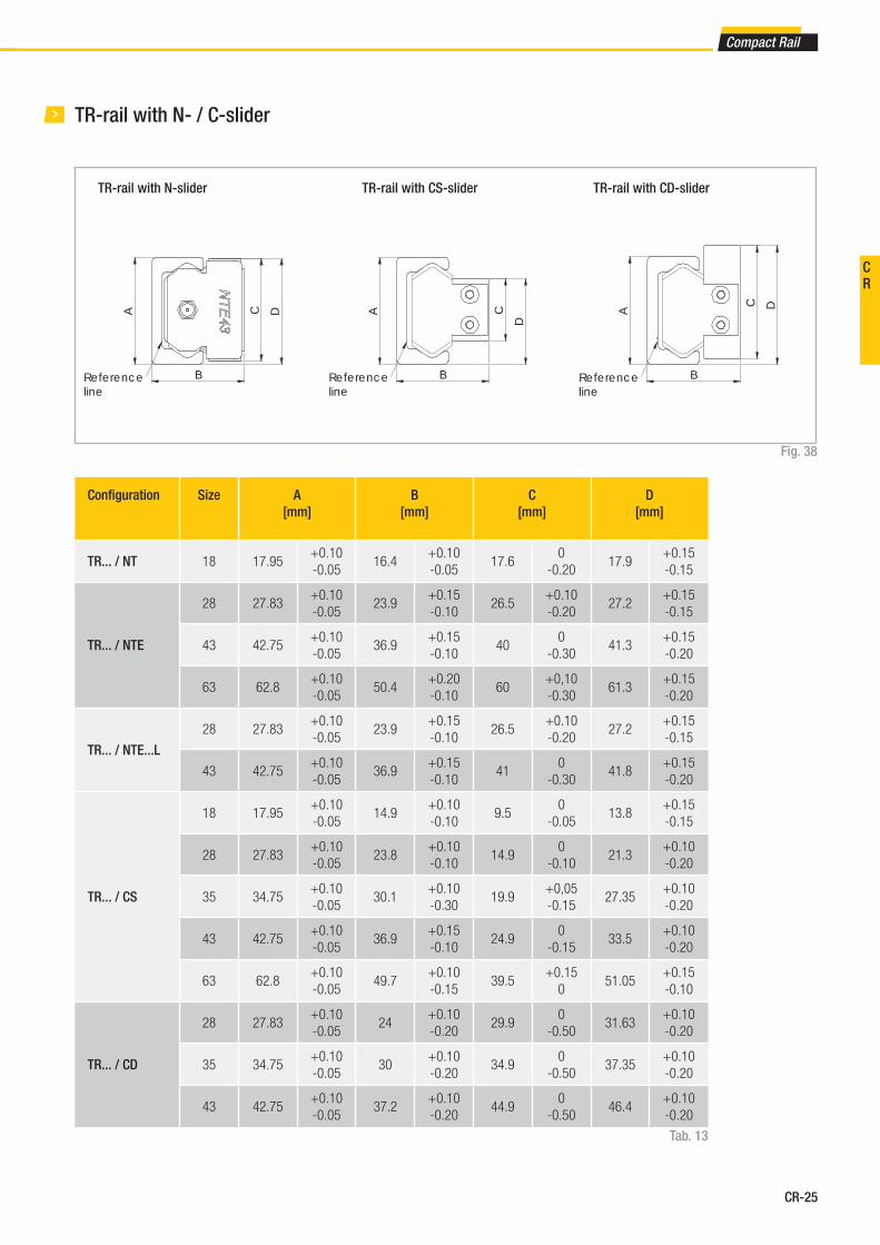
TR-rail with N- / C-slider
TR-rail with N-slider
Fig. 38
Confi guration Size A
[mm]
B
[mm]
C
[mm]
D
[mm]
TR... / NT 18 17.95+0.10
-0.0516.4
+0.10
-0.0517.6
0
-0.2017.9
+0.15
-0.15
TR... / NTE
28 27.83+0.10
-0.0523.9
+0.15
-0.1026.5
+0.10
-0.2027.2
+0.15
-0.15
43 42.75+0.10
-0.0536.9
+0.15
-0.1040
0
-0.3041.3
+0.15
-0.20
63 62.8+0.10
-0.0550.4
+0.20
-0.1060
+0,10
-0.3061.3
+0.15
-0.20
TR... / NTE...L
28 27.83+0.10
-0.0523.9
+0.15
-0.1026.5
+0.10
-0.2027.2
+0.15
-0.15
43 42.75+0.10
-0.0536.9
+0.15
-0.1041
0
-0.3041.8
+0.15
-0.20
TR... / CS
18 17.95+0.10
-0.0514.9
+0.10
-0.109.5
0
-0.0513.8
+0.15
-0.15
28 27.83+0.10
-0.0523.8
+0.10
-0.1014.9
0
-0.1021.3
+0.10
-0.20
35 34.75+0.10
-0.0530.1
+0.10
-0.3019.9
+0,05
-0.1527.35
+0.10
-0.20
43 42.75+0.10
-0.0536.9
+0.15
-0.1024.9
0
-0.1533.5
+0.10
-0.20
63 62.8+0.10
-0.0549.7
+0.10
-0.1539.5
+0.15
051.05
+0.15
-0.10
TR... / CD
28 27.83+0.10
-0.0524
+0.10
-0.2029.9
0
-0.5031.63
+0.10
-0.20
35 34.75+0.10
-0.0530
+0.10
-0.2034.9
0
-0.5037.35
+0.10
-0.20
43 42.75+0.10
-0.0537.2
+0.10
-0.2044.9
0
-0.5046.4
+0.10
-0.20
Tab. 13
TR-rail with CS-slider TR-rail with CD-slider
CR

CR-26
A C D
BReference line
A C
D
BReference line
A
C D
BReference line
U-rail with N- / C-slider
U-rail with N-slider
Fig. 39
Confi guration Size A
[mm]
Bnom*
[mm]
C
[mm]
D
[mm]
UL... / NU 18 18+0.25
-0.1016.5 17.6
0
-0.2018.3
+0.25
-0.25
UL... / NUE
28 28+0.25
-0.1024 26.5
0
-0.2028
+0.15
-0.35
43 43+0.35
-0.1037 40
0
-0.3041.9
+0.20
-0.30
63 63+0.35
-0.1050.5 60 -0.20 62
0
-0.50
UL... / NUE...L
28 28+0.25
-0.1024 26.5
0
-0.2028
+0.15
-0.35
43 43+0.35
-0.1037 41
0
-0.3042.4
+0.20
-0.35
UL... / CS
18 18+0.25
-0.1015 9.5
0
-0.0514
+0.05
-0.25
28 28+0.25
-0.1023.9 14.9
0
-0.1021.7
+0.05
-0.35
35 35+0.35
-0.1030.2 19.9
+0.05
-0.1527.85
+0.10
-0.30
43 43+0.35
-0.1037 24.9
0
-0.1534.3
+0.15
-0.30
63 63+0.35
-0.1049.8 39.5
+0.15
051.6
+0.15
-0.30
UL... / CD
28 28+0.25
-0.1024.1 29.9
0
-0.5032
+0.05
-0.35
35 35+0.35
-0.1030.1 34.9
0
-0.5037.85
+0.10
-0.30
43 43+0.35
-0.1037.3 44.9
0
-0.5047
+0.10
-0.30
U-rail with CS-slider U-rail with CD-slider
Tab. 14* see pg. CR-40 Offset T+U-system
see pg. CR-43 Offset K+U-system
3 Product dimensions
CR-27
Compact Rail
A
B
C D
Reference line
AB
C
D
Reference line
A
B
C D
Reference line
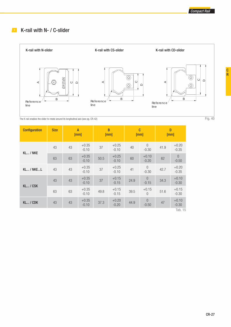
K-rail with N- / C-slider
K-rail with N-slider
Fig. 40
Confi guration Size A
[mm]
B
[mm]
C
[mm]
D
[mm]
KL... / NKE
43 43+0.35
-0.1037
+0.25
-0.1040
0
-0.3041.9
+0.20
-0.35
63 63+0.35
-0.1050.5
+0.25
-0.1060
+0.10
-0.2062
0
-0.50
KL... / NKE...L 43 43+0.35
-0.1037
+0.25
-0.1041
0
-0.3042.7
+0.20
-0.35
KL... / CSK
43 43+0.35
-0.1037
+0.15
-0.1524.9
0
-0.1534.3
+0.10
-0.30
63 63+0.35
-0.1049.8
+0.15
-0.1539.5
+0.15
051.6
+0.15
-0.30
KL... / CDK 43 43+0.35
-0.1037.3
+0.20
-0.2044.9
0
-0.5047
+0.10
-0.30
Tab. 15
The K-rail enables the slider to rotate around its longitudinal axis (see pg. CR-42)
K-rail with CS-slider K-rail with CD-slider
CR

CR-28
Confi gura-
tion
Size δ nominal
[mm]
δ maximum
[mm]
δ minimum
[mm]
TLC / NT 18 0.45 0.95 -0.25
TLC / NTE
28 0.35 0.85 -0.4
43 0.35 0.9 -0.5
63 0.35 0.8 -0.55
KLC / NKE43 0.35 0.9 -0.5
63 0.35 0.8 -0.55
ULC / NU 18 0.4 0.9 -0.25
ULC / NUE
28 0.4 0.85 -0.3
43 0.4 0.85 -0.45
63 0.35 0.8 -0.45
TLV / NT 18 0.45 0.8 -0.2
TLV / NTE
28 0.35 0.7 -0.35
43 0.35 0.75 -0.45
63 0.35 0.65 -0.55
KLV / NKE43 0.35 0.75 -0.45
63 0.35 0.65 -0.55
ULV / NU 18 0.4 0.75 -0.2
ULV / NUE
28 0.4 0.7 -0.25
43 0.4 0.7 -0.4
63 0.35 0.65 -0.45
TLC / CS
18 0.35 0.75 -0.2
28 0.25 0.6 -0.35
35 0.35 0.7 -0.35
43 0.35 0.8 -0.35
63 0.35 0.6 -0.35
KLC / CSK43 0.35 0.8 -0.35
63 0.35 0.6 -0.35
Confi gura-
tion
Size δ nominal
[mm]
δ maximum
[mm]
δ minimum
[mm]
ULC / CS
18 0.3 0.7 -0.2
28 0.3 0.6 -0.3
35 0.35 0.7 -0.35
43 0.4 0.75 -0.35
63 0.35 0.6 -0.25
TLV / CS
18 0.35 0.6 -0.15
28 0.25 0.45 -0.3
35 0.35 0.55 -0.3
43 0.35 0.65 -0.3
63 0.35 0.45 -0.35
KLV / CSK43 0.35 0.65 -0.3
63 0.35 0.45 -0.35
ULV / CS
18 0.3 0.55 -0.15
28 0.3 0.45 -0.25
35 0.35 0.55 -0.3
43 0.4 0.6 -0.3
63 0.35 0.45 -0.25
TRC / NT 18 0.15 0.65 -0.2
TRC / NTE
28 0.15 -0.5 -0.25
43 0.05 0.4 -0.3
63 0 0.4 -0.4
TRC / CS
18 0.05 0.45 -0.2
28 0.05 0.3 -0.25
35 0.1 0.35 -0.2
43 0.05 0.35 -0.25
63 0 0.2 -0.2
Tab. 16
Tab. 17
Offset of fi xing holes
Fig. 41B li i
δ
Reference lineBezugslinie
δ
Reference line
Principle representation of offset with T-rails
3 Product dimensions

CR-29
Compact Rail
A D
KHB
G
F
Ecc
en
tric
ity
A D
BH K
F
Ecc
en
tric
ity
G
Rollers
Version 1
Prismatic (T- and U-rail)
Type A
[mm]
B
[mm]
D
[mm]
e
[mm]
H
[mm]
K
[mm]
G
[mm]
F C
[N]
C0rad
[N]
Weight
[kg]
CPN18-2RS 14 4 6 - 1.55 1.8 5.5 M4 765 410 0.004
CPN18-2Z 14 4 6 - 1.55 1.8 5.5 M4 765 410 0.004
CPA18-2RS 14 4 6 0.4 1.55 1.8 5.5 M4 765 410 0.004
CPA18-2Z 14 4 6 0.4 1.55 1.8 5.5 M4 765 410 0.004
CPN28-2RS 23.2 7 10 - 2.2 3.8 7 M5 2130 1085 0.019
CPN28-2Z 23.2 7 10 - 2.2 3.8 7 M5 2130 1085 0.019
CPA28-2RS 23.2 7 10 0.6 2.2 3.8 7 M5 2130 1085 0.019
CPA28-2Z 23.2 7 10 0.6 2.2 3.8 7 M5 2130 1085 0.019
CPN35-2RS 28.2 7.5 12 - 2.55 4.2 9 M5 4020 1755 0.032
CPN35-2Z 28.2 7.5 12 - 2.55 4.2 9 M5 4020 1755 0.032
CPA35-2RS 28.2 7.5 12 0.7 2.55 4.2 9 M5 4020 1755 0.032
CPA35-2Z 28.2 7.5 12 0.7 2.55 4.2 9 M5 4020 1755 0.032
CPN43-2RS 35 11 12 - 2.5 4.5 12 M6 6140 2750 0.06
CPN43-2Z 35 11 12 - 2.5 4.5 12 M6 6140 2750 0.06
CPA43-2RS 35 11 12 0.8 2.5 4.5 12 M6 6140 2750 0.06
CPA43-2Z 35 11 12 0.8 2.5 4.5 12 M6 6140 2750 0.06
CPN63-2ZR 50 17.5 18 - 2.3 6 16 M8 15375 6250 0.19
CPA63-2ZR 50 17.5 18 1.2 2.3 6 16 M10 15375 6250 0.19
CRN43-2Z 35.6 11 12 - 2.5 4.5 12 M6 6140 2550 0.06
CRA43-2Z 35.6 11 12 0.8 2.5 4.5 12 M6 6140 2550 0.06
CRN63-2ZR 49.7 17.5 18 - 2.3 6 16 M8 15375 5775 0.19
CRA63-2ZR 49.7 17.5 18 1.2 2.3 6 16 M10 15375 5775 0.19
CPN
Concentric roller
CPA
Eccentric roller
Fig. 42
CRN
Concentric roller
CRA
Eccentric roller
Version 2
Crowned (K-rail)
Tab. 18
Seals: 2RS is the splash-proof seal, 2Z (2ZR for size 63) is the steel cover disc
Note: The rollers are lubricated for life
Accessories
CR

CR-30
Wipers for C-slider
Fig. 43
Wiper WT for T-rail Wiper WU for U-rail Wiper WK for K-rail
Sizes 43 and 63
Alignment fi xture AT (for T- and U-rail)
Fig. 44
Alignment fi xture AK (for K-rail)
Fig. 45
Rail size Alignment fi xture
18 AT 18
28 AT 28
35 AT 35
43 AT 43
63 AT 63
Tab. 19
Rail size Alignment fi xture
43 AK 43
63 AK 63
Tab. 20
4 Accessories
CR-31
Compact Rail
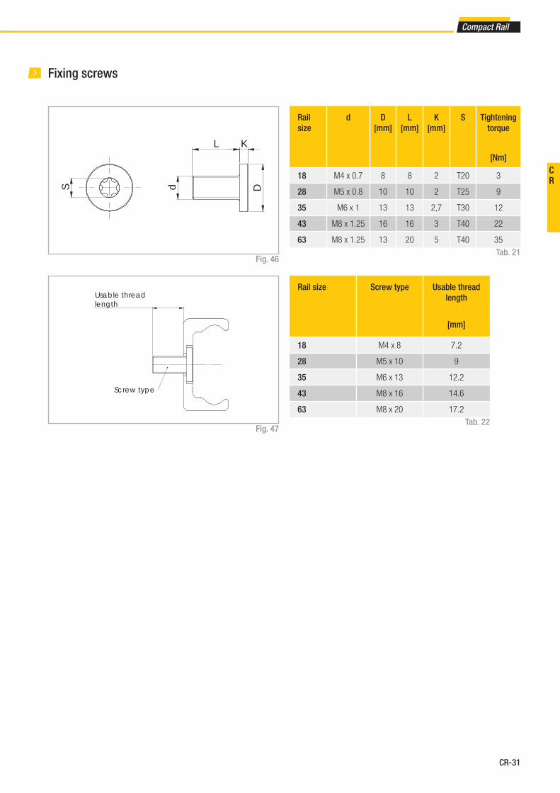
Usable thread length
Screw type
S d
L K
D
Rail
size
d D
[mm]
L
[mm]
K
[mm]
S Tightening
torque
[Nm]
18 M4 x 0.7 8 8 2 T20 3
28 M5 x 0.8 10 10 2 T25 9
35 M6 x 1 13 13 2,7 T30 12
43 M8 x 1.25 16 16 3 T40 22
63 M8 x 1.25 13 20 5 T40 35
Fig. 46Tab. 21
Rail size Screw type Usable thread
length
[mm]
18 M4 x 8 7.2
28 M5 x 10 9
35 M6 x 13 12.2
43 M8 x 16 14.6
63 M8 x 20 17.2
Tab. 22Fig. 47
Fixing screws
CR
CR-32
HH
2
W
g1
H1
H3
P2
P 1L
W1
W2
M (4 threads)
g1
H2
H
H1
W
L
M
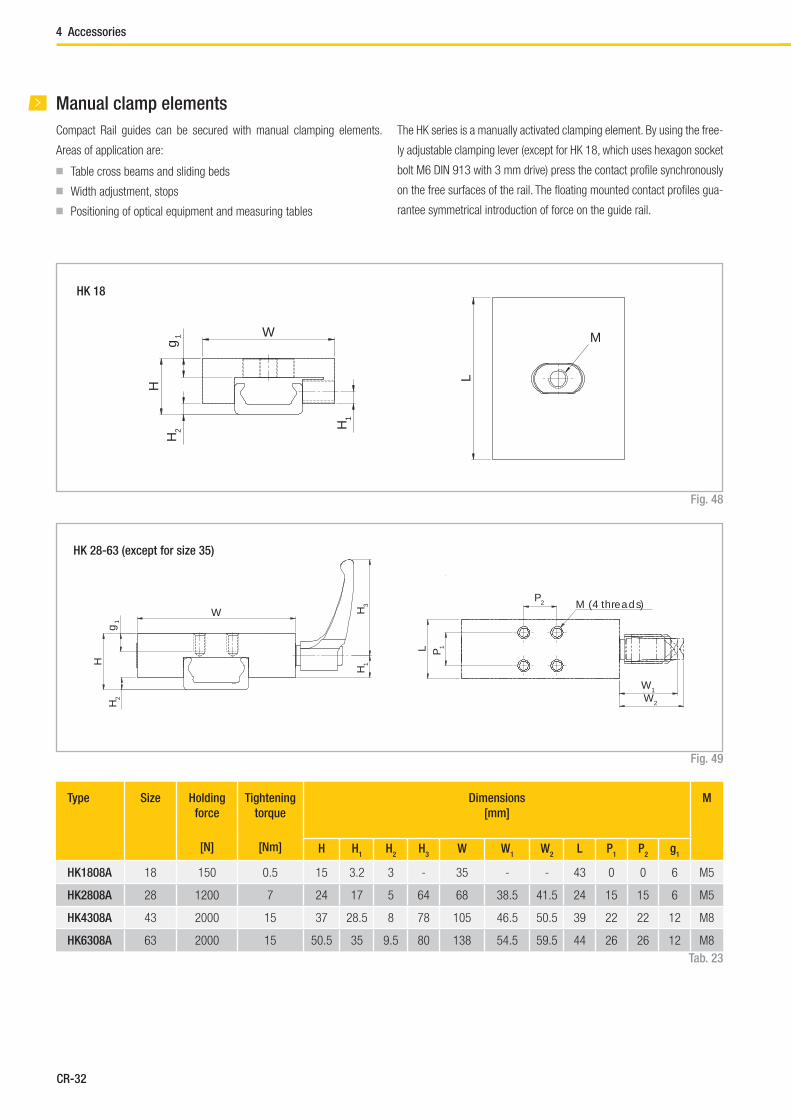
Manual clamp elements
Compact Rail guides can be secured with manual clamping elements.
Areas of application are:
■ Table cross beams and sliding beds
■ Width adjustment, stops
■ Positioning of optical equipment and measuring tables
Tab. 23
Type Size Holding
force
[N]
Tightening
torque
[Nm]
Dimensions
[mm]
M
H H1
H2
H3
W W1
W2
L P1
P2
g1
HK1808A 18 150 0.5 15 3.2 3 - 35 - - 43 0 0 6 M5
HK2808A 28 1200 7 24 17 5 64 68 38.5 41.5 24 15 15 6 M5
HK4308A 43 2000 15 37 28.5 8 78 105 46.5 50.5 39 22 22 12 M8
HK6308A 63 2000 15 50.5 35 9.5 80 138 54.5 59.5 44 26 26 12 M8
The HK series is a manually activated clamping element. By using the free-
ly adjustable clamping lever (except for HK 18, which uses hexagon socket
bolt M6 DIN 913 with 3 mm drive) press the contact profile synchronously
on the free surfaces of the rail. The floating mounted contact profiles gua-
rantee symmetrical introduction of force on the guide rail.
Fig. 48
Fig. 49
HK 18
HK 28-63 (except for size 35)
4 Accessories
CR-33
Compact Rail
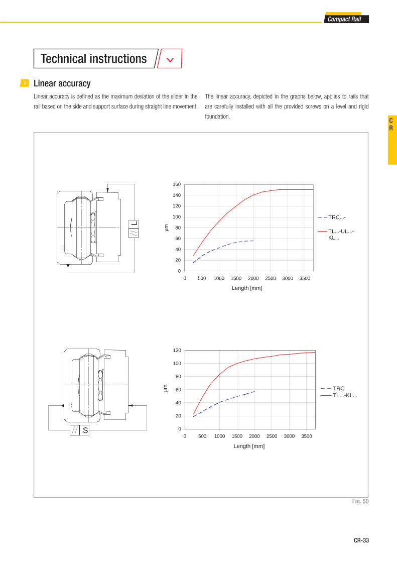
Linear accuracy
Linear accuracy is defi ned as the maximum deviation of the slider in the
rail based on the side and support surface during straight line movement.
Fig. 50
The linear accuracy, depicted in the graphs below, applies to rails that
are carefully installed with all the provided screws on a level and rigid
foundation.
0
20
40
60
80
100
120
140
160
0 500 1000 1500 2000 2500 3000 3500
Length [mm]
TRC...-
TL...-UL...-KL...
µm
0
20
40
60
80
100
120
0 500 1000 1500 2000 2500 3000 3500
Length [mm]
µm TRCTL...-KL...
S
L
Technical instructions
CR

CR-34
Type TL..., UL..., KL...
TRC
ΔL [mm]
Slider with equal arrangement
0.2
ΔL [mm]
Slider with opposite arrangement
1.0
ΔS [mm] 0.05
Tab. 24
Deviation of accuracy with two 3 roller sliders in one rail
5 Technical instructions
CR-35
Compact Rail
0
50
100
150
200
250
300
350
400
0 500 1000 1500 2000 2500 3000 3500 4000 4500 5000 5500
δ [μ
m]
P [N]
18
28
35
43
0
50
100
150
200
250
0 500 1000 1500 2000 2500 3000 3500 4000 4500 5000 5500
δ [μ
m]
P [N]
18
28
35
43
P
δ
P
δ
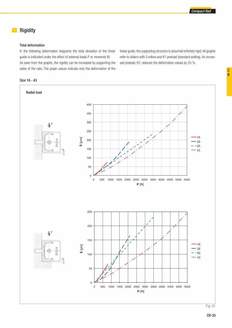
Rigidity
Total deformation
In the following deformation diagrams the total deviation of the linear
guide is indicated under the effect of external loads P or moments M.
As seen from the graphs, the rigidity can be increased by supporting the
sides of the rails. The graph values indicate only the deformation of the
linear guide, the supporting structure is assumed infi nitely rigid. All graphs
refer to sliders with 3 rollers and K1 preload (standard setting). An increa-
sed preload, K2, reduces the deformation values by 25 %.
Fig. 51
Radial load
Size 18 - 43
CR

CR-36
0
20
40
60
80
100
120
140
0 200 400 600 800 1000 1200 1400 1600
δ [μ
m]
P [N]
18
28
35
43
0
2
4
6
8
10
12
14
0 2 4 6 8 10 12 14 16 18 20 22 24
δ [m
rad]
Mx [Nm]
18
28
35
43
δ
Mx
δ
P
Fig. 52
Axial load
Moment Mx
5 Technical instructions

CR-37
Compact Rail
Fig. 53
Size 63
0
50
100
150
200
250
300
350
0 2000 4000 6000 8000 10000 12000 14000
δ [μ
m]
NT/NU63
CS63
0
50
100
150
200
250
300
350
400
450
0 2000 4000 6000 8000 10000 12000 14000
δ [μ
m]
P [N]
NT/NU63
CS63
δ
P
δ
P
Radial load
CR
CR-38
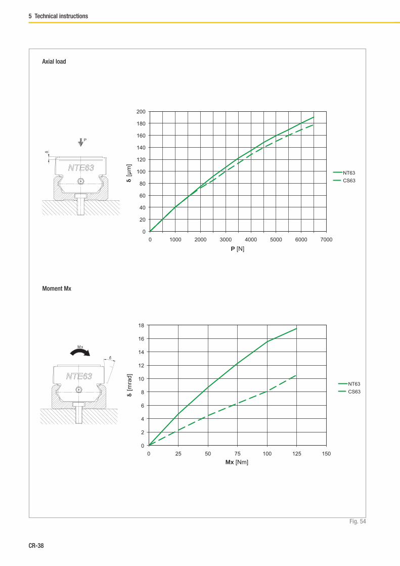
Fig. 54
0
20
40
60
80
100
120
140
160
180
200
0 1000 2000 3000 4000 5000 6000 7000
δ [μ
m]
P [N]
NT63
CS63
0
2
4
6
8
10
12
14
16
18
0 25 50 75 100 125 150
δ [m
rad]
Mx [Nm]
NT63
CS63
δ
Mx
δ
P
Axial load
Moment Mx
5 Technical instructions
CR-39
Compact Rail
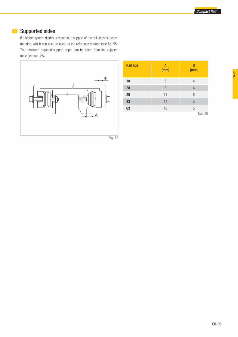
Supported sides
Rail size A
[mm]
B
[mm]
18 5 4
28 8 4
35 11 5
43 14 5
63 18 5
Tab. 25
Fig. 55
If a higher system rigidity is required, a support of the rail sides is recom-
mended, which can also be used as the reference surface (see fi g. 55).
The minimum required support depth can be taken from the adjacent
table (see tab. 25).
CR
CR-40
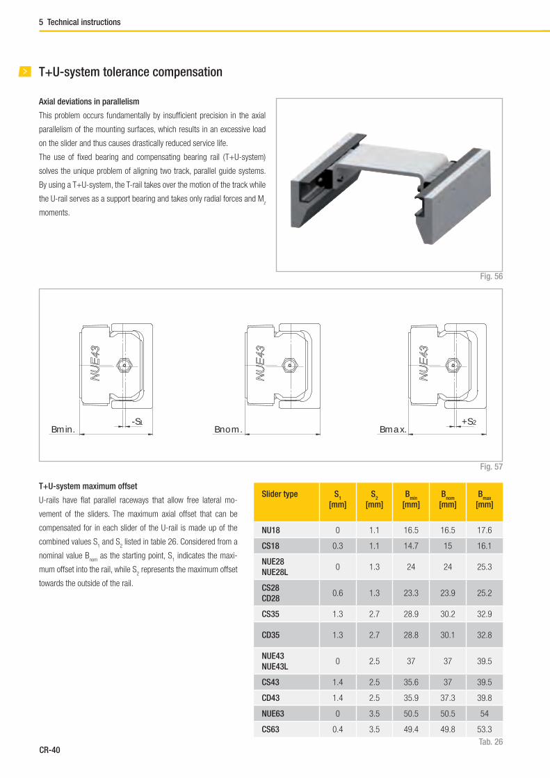
Slider type S1
[mm]
S2
[mm]
Bmin
[mm]
Bnom
[mm]
Bmax
[mm]
NU18 0 1.1 16.5 16.5 17.6
CS18 0.3 1.1 14.7 15 16.1
NUE28
NUE28L0 1.3 24 24 25.3
CS28
CD280.6 1.3 23.3 23.9 25.2
CS35 1.3 2.7 28.9 30.2 32.9
CD35 1.3 2.7 28.8 30.1 32.8
NUE43
NUE43L0 2.5 37 37 39.5
CS43 1.4 2.5 35.6 37 39.5
CD43 1.4 2.5 35.9 37.3 39.8
NUE63 0 3.5 50.5 50.5 54
CS63 0.4 3.5 49.4 49.8 53.3
Tab. 26
Fig. 57
T+U-system maximum offset
U-rails have fl at parallel raceways that allow free lateral mo-
vement of the sliders. The maximum axial offset that can be
compensated for in each slider of the U-rail is made up of the
combined values S1 and S
2 listed in table 26. Considered from a
nominal value Bnom
as the starting point, S1 indicates the maxi-
mum offset into the rail, while S2 represents the maximum offset
towards the outside of the rail.
Bmin.-S1
Bmax.+S2
Bnom.
T+U-system tolerance compensation
Axial deviations in parallelism
This problem occurs fundamentally by insuffi cient precision in the axial
parallelism of the mounting surfaces, which results in an excessive load
on the slider and thus causes drastically reduced service life.
The use of fi xed bearing and compensating bearing rail ( T+U-system)
solves the unique problem of aligning two track, parallel guide systems.
By using a T+U-system, the T-rail takes over the motion of the track while
the U-rail serves as a support bearing and takes only radial forces and Mz
moments.
Fig. 56
5 Technical instructions

CR-41
Compact Rail
The application example in the adjacent drawing (see fi g. 59) shows that
the T+U-system implements a problem-free function of the slider even
with an angled offset in the mounting surfaces.
If the length of the guide rails is known, the maximum allowable angle
deviation of the screwed surfaces can be determined using this formula
(the slider in the U-rail moves here from the innermost position S1 to ou-
termost position S2 ):
Size Rail length
[mm]
Offset S
[mm]
Angle α[°]
18 2000 1.4 0.040
28 3200 1.9 0.034
35 3600 4 0.063
43 3600 3.9 0.062
63 3600 3.9 0.062
S* = Sum of S1 and S
2
L = Length of rail
Fig. 58
Fig. 59
α = arctanS*
L
The following table (tab. 27) contains guidelines for this maximum an-
gle deviation α, achievable with the longest guide rail from one piece.
Tab. 27
The T+U-system can be designed in different arrangements (see fi g. 60).
A T-rail accepts the vertical components of load P. A U-rail attached un-
derneath the component to be guided prevents the vertical panel from
swinging and is used as moment support. In addition a vertical offset
in the structure, as well as possible existing unevenness of the support
surface, is compensated for.
Fig. 60
L
S
α
CR

CR-42
K+U-system tolerance compensation
Deviations in parallelism in two planes
The K+U-system, like the T+U-system, can compensate for axial devi-
ations in parallelism. Additionally, the K+U system has the option of ro-
tating the slider in the rail, which will compensate for other deviations in
parallelism, e.g. height offset.
The unique raceway contour of the K-rail allows the slider a certain ro-
tation around its longitudinal axis, with the same linear precision as with
a T-rail. With the use of a K+U-system, the K-rail accounts for the main
loads and the motion of the track. The U-rail is used as a support bearing
and takes only radial forces and Mz moments. The K-rail must always be
installed so that the radial load of the slider is always supported by at least
2 load bearing roller sliders, which lie on the V-shaped raceway (reference
line) of the rail.
Fig. 62
K-rails and sliders are available in both sizes 43 and 63.
The custom NKE-slider may only be used in K-rails and cannot be ex-
changed with other Rollon sliders. The maximum allowable rotation angle
of the NKE- and NUE-sliders are shown in the following table 28 and fi gure
62. α1 is the maximum rotation angle counterclockwise, α
2 is clockwise.
Slider type α1
[°]
α2
[°]
NKE43 and NUE43 2 2
NKE63 and NUE63 1 1
Tab. 28
Fig. 61
NKE43
NU
E43
α α
1α
NKE
α 2
NKE
5 Technical instructions
CR-43
Compact Rail
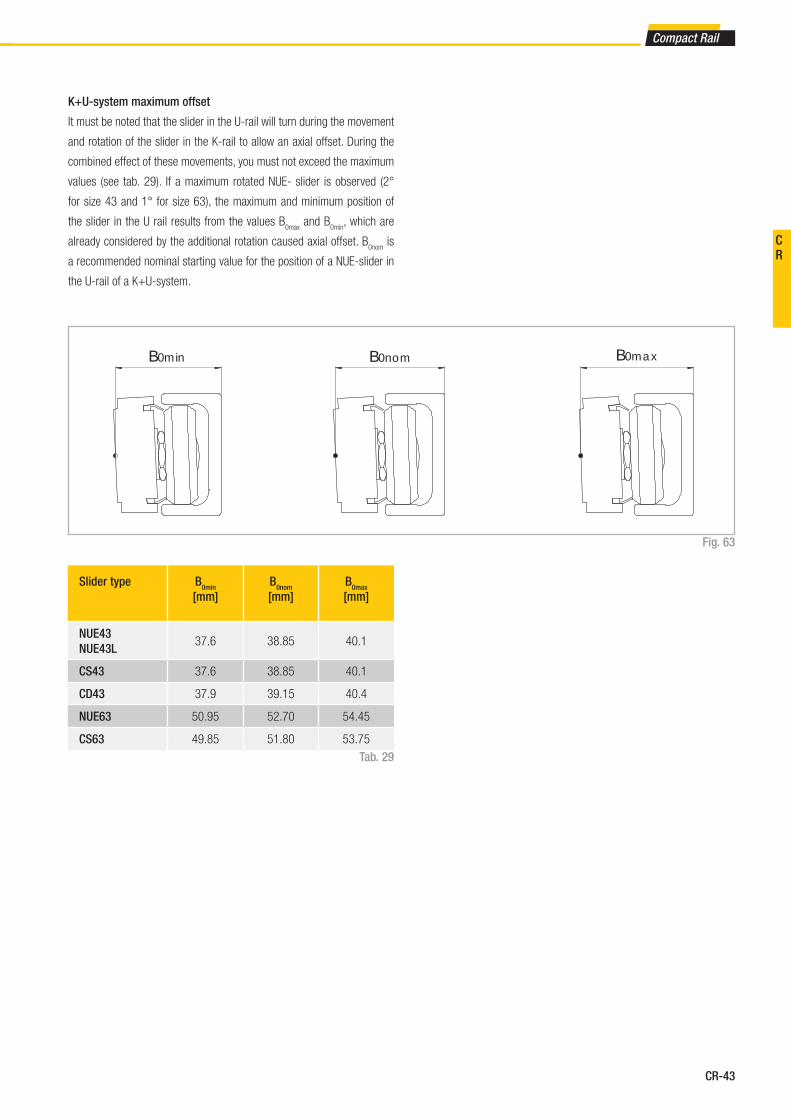
K+U-system maximum offset
It must be noted that the slider in the U-rail will turn during the movement
and rotation of the slider in the K-rail to allow an axial offset. During the
combined effect of these movements, you must not exceed the maximum
values (see tab. 29). If a maximum rotated NUE- slider is observed (2°
for size 43 and 1° for size 63), the maximum and minimum position of
the slider in the U rail results from the values B0max
and B0min
, which are
already considered by the additional rotation caused axial offset. B0nom
is
a recommended nominal starting value for the position of a NUE-slider in
the U-rail of a K+U-system.
Slider type B0min
[mm]
B0nom
[mm]
B0max
[mm]
NUE43
NUE43L37.6 38.85 40.1
CS43 37.6 38.85 40.1
CD43 37.9 39.15 40.4
NUE63 50.95 52.70 54.45
CS63 49.85 51.80 53.75
Tab. 29
Fig. 63
B0min B0nom B0max
CR

CR-44
Even the K+U-system can be used in different arrangements. If the same
example as with the T+U-system is observed (see pg. CR-41, fi g. 60),
this solution, in addition to the prevention of vibrations and moments, also
enables the compensation of larger deviations in parallelism in the vertical
direction, without negative consequences to the guide. This is particularly
important for longer strokes as it is more diffi cult to obtain a correct ver-
tical parallelism.
Fig. 65
If a K-rail is used in combination with a U-rail, with guaranteed problem-
free running and without extreme slider load, a pronounced height diffe-
rence between the two rails can also be compensated for. The following
illustration shows the maximum height offset b of the mounting surfaces
in relation to the distance a of the rails (see fi g. 64).
Fig. 64
100
75
50
25
0
-25
-50
-75
-100
0 250 500 750 1000 1250 1500 1750 2000 2250 2500
Size 43
Size 63
b -
max
imum
hei
ght o
ffset
(mm
)a - distance between the rails (mm )
b
a
NKE43
NU
E43
5 Technical instructions

CR-45
Compact Rail
Preload
Preload classes
The factory installed systems, consisting of rails and sliders, are available
in two preload classes:
Standard preload K1 means a rail-slider combination with minimum pre-
load which means the rollers are adjusted free of clearance for optimal
running properties.
Usually preload K2 is used for rail-slider systems for increasing the rigidity
(see pg. CR-35). When using a system with K2 preload a reduction of the
loading capacities and service life must be taken into consideration (see
tab. 30).
Preload class Reduction y
K1 -
K2 0.1
Preload class Interference*
[mm]
Rail type
K1 0.01 all
K2
0.03 T, U...18
0.04 T, U...28
0.05 T, U...35
0.06T, U, K...43,
T, U, K...63
Tab. 30
Tab. 31
This coeffi cient y is used in the calculation formula for checking the static
load and lifetime (see pg. CR-50, fi g. 75 and pg. CR-54, fi g. 92).
The interference is the difference between the contact lines of the rollers
and the raceways of the rail.
* Measured on the largest interior dimension between the raceways
CR
CR-46
Size A
[mm]
18 40
28 55
35 75
43 80
63 120
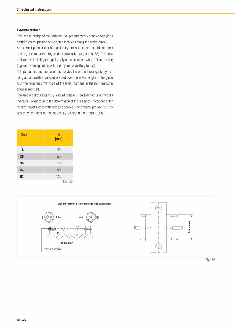
External preload
The unique design of the Compact Rail product family enables applying a
partial external preload on selected locations along the entire guide.
An external preload can be applied by pressure along the side surfaces
of the guide rail according to the drawing below (see fi g. 66). This local
preload results in higher rigidity only at the locations where it is necessary
(e.g. on reversing points with high dynamic auxiliary forces).
This partial preload increases the service life of the linear guide by avo-
iding a continually increased preload over the entire length of the guide.
Also the required drive force of the linear carriage in the non-preloaded
areas is reduced.
The amount of the externally applied preload is determined using two dial
indicators by measuring the deformation of the rail sides. These are defor-
med by thrust blocks with pressure screws. The external preload must be
applied when the slider is not directly located in the pressure zone.
Fig. 66
Tab. 32
Dial indicator for determining the side deformation
A m
inim
um
Thrust block
Pressure screws
5 Technical instructions

CR-47
Compact Rail
The graph below indicates the value of the equivalent load as a function
of the total deformation of both rail sides. The data relates to sliders with
three rollers (see fi g. 67).
Fig. 67
δ [μm]
Equiv
ale
nt lo
ad [%
C0ra
d] C
R

CR-48
5 Technical instructions
Drive force
Frictional resistance
The drive force required for moving the slider is determined by the com-
bined resistance of the rollers, wipers and seals.
The ground raceways and rollers have a minimal coeffi cient of friction,
which remains almost the same in both the static and dynamic state.
The wiper and longitudinal seals are designed for an optimum protection
of the system, without a signifi cant negative infl uence on the quality of
motion. The overall friction of the Compact Rail also depends on external
factors such as lubrication, preload and additional forces. Table 33 below
contains the coeffi cients of friction for each slider type (for CSW and CDW
sliders no friction occurs to μs ).
Fig. 68
Tab. 33
Size μ Roller friction μw Wiper friction μ
s Friction of longitudinal seals
18 0.003 0.0015
28 0.003
35 0.005
43 0.005
63 0.006
In ( m · 1000 )*
0.98 · m · 1000
In ( m · 1000 )*
0.06 · m · 1000
In ( m · 1000 )*
0.15 · m · 1000
* Kilograms must be used for load m
Calculation of drive force
The minimum required drive force for the slider is determined with the
coeffi cients of friction (see tab. 33) and the following formula (see fi g. 69):
Fig. 69
Example calculation:
If a NTE43 slider is used with a radial load of 100 kg, the result is
μ = 0.005; from the formula the following is calculated:
Fig. 70
In (100 000)
0.15 · 100 000μ
s = = 0.00076
In (100 000)
0.06 · 100 000μ
w = = 0.0019
This is the minimum drive force for this example:
F = ( 0.005 + 0.0019 + 0.00076 ) · 100 · 9.81 = 7.51 N
Fig. 71
F = ( μ + μw + μ
s ) · m · g
m = mass (kg)
g = 9.81 m/s2
The values given in Table 33 apply to external loads, which, with sliders
with three rollers, are at least 10 % of the maximum load rating. For cal-
culating the driving force for lower loads, please contact Rollon technical
support.

CR-49
Compact Rail
Fig. 72
0
0,0025
0,0050
0,0075
0,0100
0,0125
0,0150
0,0175
0,0200
0,0225
0 0,025 0,050 0,075 0,100 0,125 0,150 0,175 0,200 0,225 0,250 0,275 0,300
Rolle
r fric
tion
μ
Duty factor P/C0
Size 18
0
0,01
0,02
0,03
0,04
0,05
0,06
0,07
0,08
0,09
0,10
0,11
0 0,02 0,04 0,06 0,08 0,10 0,12 0,14 0,16 0,18 0,20
Rolle
r fric
tion
μ
Duty factor P/C0
Size 28
Size 35
Size 43
0
0,01
0,02
0,03
0,04
0,05
0,06
0,07
0,08
0,09
0,10
0,11
0,12
0 0,01 0,02 0,03 0,04 0,05 0,06 0,07 0,08 0,09 0,10
Rolle
r fric
tion
μ
Duty factor P/C0
Size 63
CR

CR-50
5 Technical instructions
Static load
The radial load capacity rating, C0rad
the axial load capacity rating C0ax
, and
moments Mx, M
y, M
z indicate the maximum permissible values of the load
(see pg. CR-9ff), higher loads will have a detrimental effect on the running
quality. A safety factor, S0, is used to check the static load, which takes
into account the basic parameters of the application and is defi ned more
in detail in the following table:
Safety factor S0
Fig. 73
No shock nor vibration, smooth and low-frequency reverse,
high assembly accuracy, no elastic deformations1 - 1.5
Normal installation conditions 1.5 - 2
Shock and vibration, high-frequency reverse, signifi cant elastic deformation 2 - 3.5
Fig. 74
Fig. 75
The above formulas are valid for a single load case.
If two or more forces are acting simultaneously, please check the following
formula:
The ratio of the actual load to maximum permissible load may be as large
as the reciprocal of the accepted safety factor, S0, at the most.
P0rad
1
C0rad
S0
≤P
0ax 1
C0ax
S0
≤M
1 1
Mx S
0
≤M
2 1
My S
0
≤M
3 1
Mz S
0
≤
P0rad
= effective radial load (N)
C0rad
= permissible radial load (N)
P0ax
= effective axial load (N)
C0ax
= permissible axial load (N)
M1, M
2, M
3 = external moments ( Nm)
Mx, M
y, M
z = maximum permissible moments
in the different loading directions (Nm)
y = reduction due to preload
P0rad
P0ax
M1 M
2 M
3
C0rad
C0ax
Mx M
y M
z
+ + + + + y ≤1
S0
The safety factor S0 can lie on the lower given limit if the occurring forces
can be determined with suffi cient precision. If shock and vibration are pre-
sent, the higher value should be selected. For dynamic applications higher
safety is required. Please contact Rollon technical support.
CR-51
Compact Rail
c
a b
FF
FP1 P2
M1
F
b a
F
P1
P2
b
a
F
P2a
P2b
P1a
P1b
F
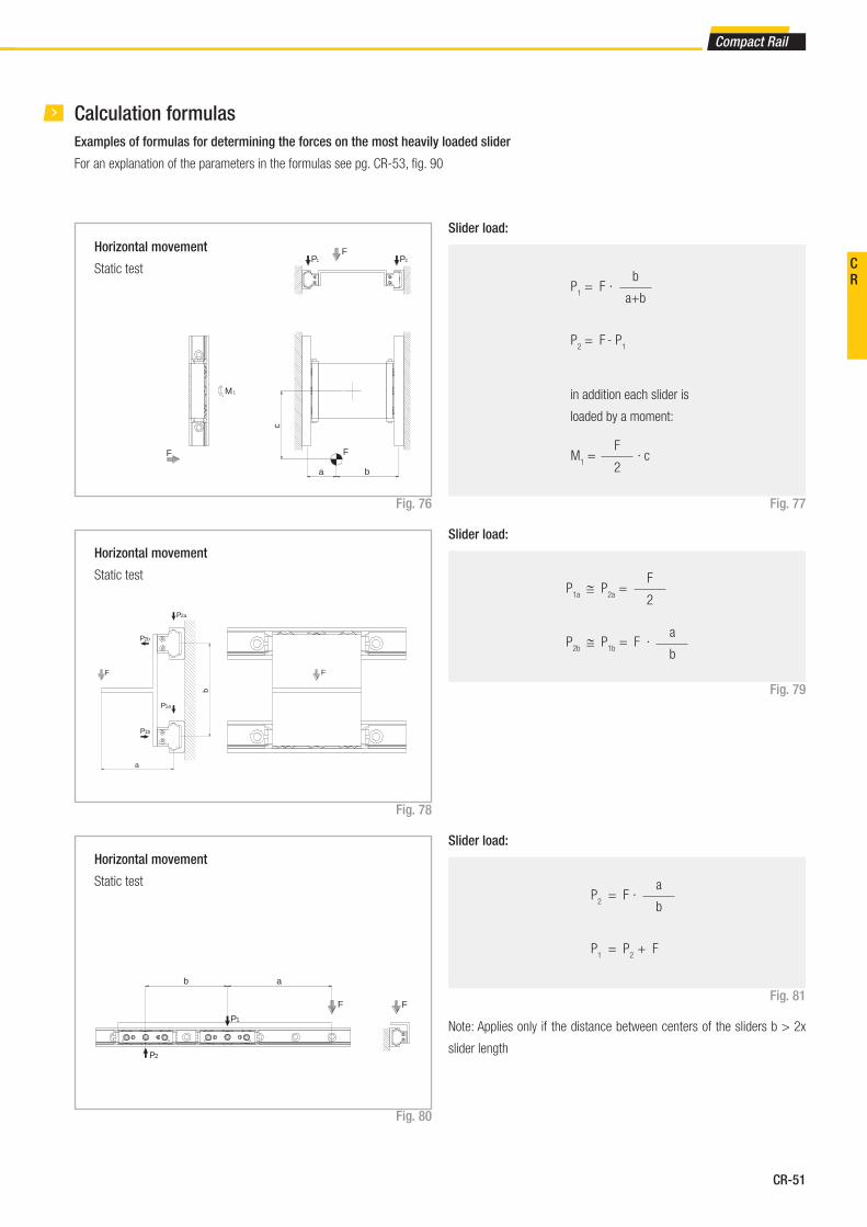
Examples of formulas for determining the forces on the most heavily loaded slider
For an explanation of the parameters in the formulas see pg. CR-53, fi g. 90
Horizontal movement
Static test
Slider load:
Fig. 77
b
a+bP
1 = F
·
P2 = F
- P
1
F
2M
1 =
· c
in addition each slider is
loaded by a moment:
Fig. 76
Horizontal movement
Static test
Slider load:
Fig. 79
Fig. 78
F
2P
1a ≅ P
2a =
P2b
≅ P1b
= F · a
b
Horizontal movement
Static test
Slider load:
Fig. 81
Fig. 80
a
bP
2 = F
·
P1 = P
2 + F
Calculation formulas
Note: Applies only if the distance between centers of the sliders b > 2x
slider length
CR

CR-52
a
F
P1
M2
a
b
F
P2
P1
d
b
a
c
P1
P2
P3
P4
F
P3-4P1-2
5 Technical instructions
Horizontal movement
Static test
Slider load:
Fig. 83Fig. 82
Note: It is defi ned that slider no. 4 is always located closest to the point
where the force is applied.
F
4P
1 = - ( · ) - ( · )
F
2
b
c
F
2
a
d
F
4P
2 = - ( · ) + ( · )
F
2
b
c
F
2
a
d
F
4P
3 = + ( · ) - ( · )
F
2
b
c
F
2
a
d
F
4P
4 = + ( · ) + ( · )
F
2
b
c
F
2
a
d
Vertical movement
Static test
Slider load:
Fig. 85
Fig. 84
a
bP
1 ≅ P
2 = F ·
Horizontal movement
Static test
Slider load:
Fig. 87
Fig. 86
P1 = F
M2 = F · a
Note: Applies only if the distance between centers of the sliders b > 2x
slider length
CR-53
Compact Rail
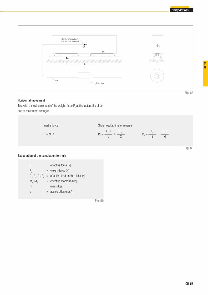
Fig. 88
Horizontal movement
Test with a moving element of the weight-force Fg at the instant the direc-
tion of movement changes
Fig. 89
Inertial force
F = m · a
Slider load at time of reverse
F · I
dP
1 =
+
Fg
2
Fg
2P
2 =
-
F · I
d
F = effective force (N)
Fg = weight-force (N)
P1, P
2, P
3, P
4 = effective load on the slider (N)
M1, M
2 = effective moment (Nm)
m = mass (kg)
a = acceleration (m/s²)
d
l
Fg
F
P1
P2
Direction
Drive
Center of gravity of the moving element
Fg
Fig. 90
Explanation of the calculation formula
CR

CR-54
5 Technical instructions
Service life calculation
The dynamic load capacity C is a conventional variable used for calculating
the service life. This load corresponds to a nominal service life of 100 km.
For values of the individual slider see pg. CR-9. Load capacities. The fol-
lowing formula (see fi g. 91) links the calculated theoretical service life to
the dynamic load capacity and the equivalent load:
Fig. 91
LKm
= 100 · ( ––– · ––– · fh )3
C
P
fc
fi
Lkm
= theoretical service life ( km )
C = dynamic load capacity ( N )
P = effective equivalent load ( N )
fc = contact factor
fi = application coeffi cient
fh = stroke factor
The equivalent load P corresponds in its effects to the sum of the forces
and moments working simultaneously on a slider. If these different load
components are known, P results as follows:
Here the external loads are assumed as constant in time. Brief loads,
which do not exceed the maximum load capacities, do not have any rele-
vant effect on the service life and can therefore be neglected.
The contact factor fc refers to applications in which several sliders pass
the same rail section. If two or more sliders move over the same point of
a rail, the contact factor according to table 34 to be taken into account in
the formula for calculation of the service life.
Number of sliders 1 2 3 4
fc
1 0.8 0.7 0.63
Tab. 34
y = reduction due to preloadP
a M
1 M
2 M
3
C0ax
Mx M
y M
z
P = Pr + ( + + + + y ) · C
0rad
Fig. 92
CR-55
Compact Rail
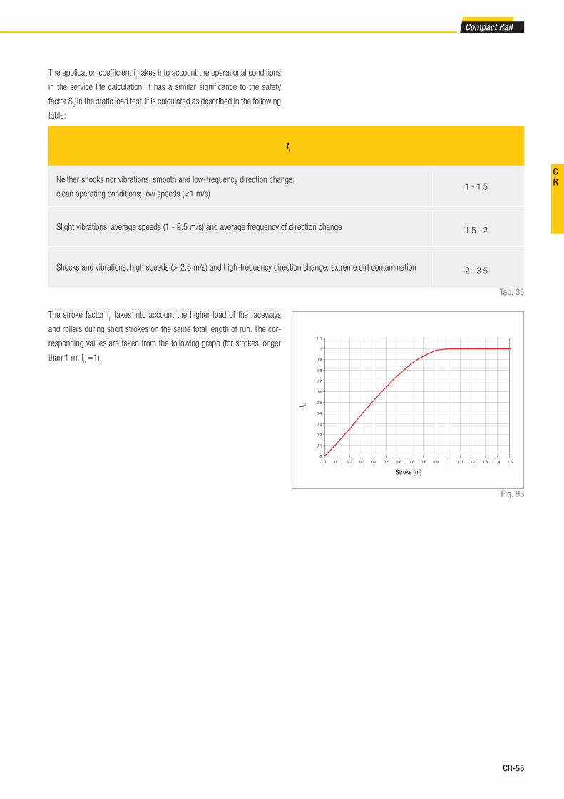
Fig. 93
fi
Neither shocks nor vibrations, smooth and low-frequency direction change;
clean operating conditions; low speeds (<1 m/s)1 - 1.5
Slight vibrations, average speeds (1 - 2.5 m/s) and average frequency of direction change 1.5 - 2
Shocks and vibrations, high speeds (> 2.5 m/s) and high-frequency direction change; extreme dirt contamination 2 - 3.5
The application coeffi cient fi takes into account the operational conditions
in the service life calculation. It has a similar signifi cance to the safety
factor S0 in the static load test. It is calculated as described in the following
table:
The stroke factor fh takes into account the higher load of the raceways
and rollers during short strokes on the same total length of run. The cor-
responding values are taken from the following graph (for strokes longer
than 1 m, fh =1):
Tab. 35
Stroke [m]
f h
CR
CR-56
5 Technical instructions
Lubrication
Roller pin lubrication
The bearings inside the Rollers are lubricated for life. To reach the cal-
culated service life (see pg. CR-54), a fi lm of lubricant should always be
Tab. 36
Lubrication of the raceways
Proper lubrication during normal conditions:
■ reduces friction
■ reduces wear
■ reduces the load of the contact surfaces through elastic deformations
■ reduces running noise
Lubricant Thickening agent Temperature range
[°C]
Dynamic viscosity
[mPa·s]
Mineral oil Lithium soap -20... to +120 < 1000
Fig. 94
Replacement of N-slider wiper head
Sliders NTE, NUE and NKE are equipped with a safety system made of
longitudinal sealing lips and rigid, spring-preloaded, and therefore self-
adjusting, wipers on both sides of the head for automatic cleaning of the
raceways. The slider heads can be removed for replacement. To do this it
is necessary to loosen the zerk fi ttings (except for types NT/NU18), which
should be refastened after installing the new heads with the following
tightening torque:
Slider type Tightening
torque [Nm]
NTE, NUE28 0.4 - 0.5
NTE, NUE, NKE43 and 63 0.6 - 0.7
Tab. 37
N-slider lubrication
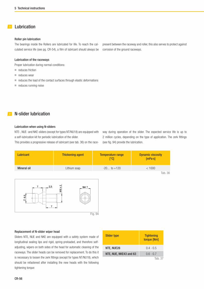
Lubrication when using N-sliders
NTE-, NUE- and NKE-sliders (except for types NT/NU18) are equipped with
a self-lubrication kit for periodic lubrication of the slider.
This provides a progressive release of lubricant (see tab. 36) on the race-
way during operation of the slider. The expected service life is up to
2 million cycles, depending on the type of application. The zerk fi ttings
(see fi g. 94) provide the lubrication.
6,5
7 2,5
7
M6
x 1
SW 7
6,5
7 2,5
7
M6
x 1
SW 7
present between the raceway and roller, this also serves to protect against
corrosion of the ground raceways.
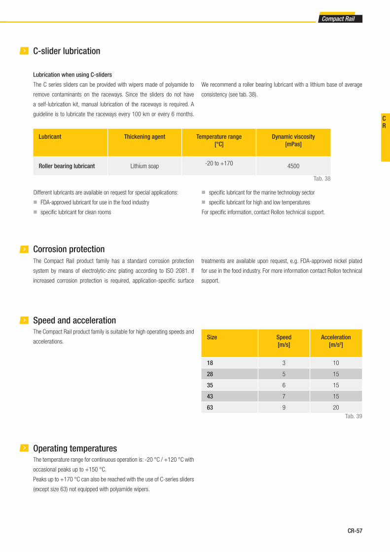
CR-57
Compact Rail
Lubricant Thickening agent Temperature range
[°C]
Dynamic viscosity
[mPas]
Roller bearing lubricant Lithium soap -20 to +170 4500
Tab. 38
Operating temperatures
C-slider lubrication
Lubrication when using C-sliders
The C series sliders can be provided with wipers made of polyamide to
remove contaminants on the raceways. Since the sliders do not have
a self-lubrication kit, manual lubrication of the raceways is required. A
guideline is to lubricate the raceways every 100 km or every 6 months.
We recommend a roller bearing lubricant with a lithium base of average
consistency (see tab. 38).
Corrosion protection
The Compact Rail product family has a standard corrosion protection
system by means of electrolytic-zinc plating according to ISO 2081. If
increased corrosion protection is required, application-specifi c surface
treatments are available upon request, e.g. FDA-approved nickel plated
for use in the food industry. For more information contact Rollon technical
support.
Speed and accelerationThe Compact Rail product family is suitable for high operating speeds and
accelerations. Size Speed
[m/s]
Acceleration
[m/s2]
18 3 10
28 5 15
35 6 15
43 7 15
63 9 20
Tab. 39
The temperature range for continuous operation is: -20 °C / +120 °C with
occasional peaks up to +150 °C.
Peaks up to +170 °C can also be reached with the use of C-series sliders
(except size 63) not equipped with polyamide wipers.
Different lubricants are available on request for special applications:
■ FDA-approved lubricant for use in the food industry
■ specifi c lubricant for clean rooms
■ specifi c lubricant for the marine technology sector
■ specifi c lubricant for high and low temperatures
For specifi c information, contact Rollon technical support.
CR

CR-58
Chamfer
6 Installation instructions
Fixing holes
V-holes with 90° bevels
The selection of rails with 90° countersunk holes is based on the precise
alignment of the threaded holes for installation. Here the complex align-
ment of the rail to an external reference is omitted, since the rail aligns
during installation by the self-centering of the countersunk screws on the
existing hole pattern.
Fig. 95
C-holes with cylindrical counterbore
The cylindrical screw has, as shown, some play in the countersunk fi xing
hole, so that an optimum alignment of the rail can be achieved during
installation (see fi g. 96).
The area T is the diameter of the possible offset, in which the screw center
point can move during the precise alignment.
Fig. 96
Rail type Area T
[mm]
TLC18 - ULC18 ∅ 1.0
TLC28 - ULC28 ∅ 1.0
TLC35 - ULC35 ∅ 1.5
TLC43 - ULC43 - KLC43 ∅ 2.0
TLC63 - ULC63 - KLC63 ∅ 1.0
Tab. 40
The minimum chamfers on the fi xing threads are listed on the table below.
Size Chamfer
[mm]
18 0.5 x 45°
28 0.6 x 45°
35 0.5 x 45°
43 1 x 45°
63 0.5 x 45°
Fig. 97Tab. 41
Minimum diameter of the rail hole
Screw diameter
Area T
Example for fi xing with Torx® screws (custom design)
Installation instructions
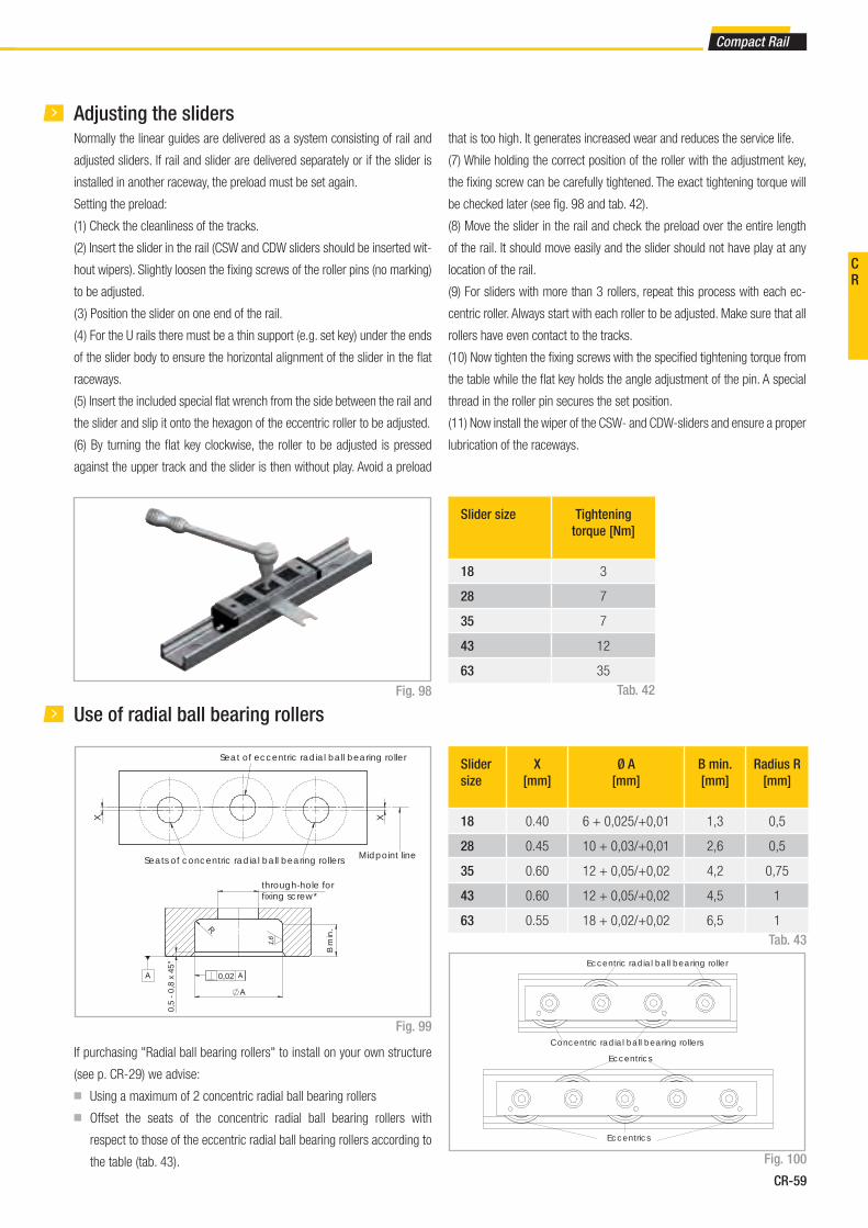
CR-59
Compact Rail
Normally the linear guides are delivered as a system consisting of rail and
adjusted sliders. If rail and slider are delivered separately or if the slider is
installed in another raceway, the preload must be set again.
Setting the preload:
(1) Check the cleanliness of the tracks.
(2) Insert the slider in the rail (CSW and CDW sliders should be inserted wit-
hout wipers). Slightly loosen the fi xing screws of the roller pins (no marking)
to be adjusted.
( 3 ) Position the slider on one end of the rail.
(4 ) For the U rails there must be a thin support (e.g. set key) under the ends
of the slider body to ensure the horizontal alignment of the slider in the fl at
raceways.
(5) Insert the included special fl at wrench from the side between the rail and
the slider and slip it onto the hexagon of the eccentric roller to be adjusted.
(6) By turning the fl at key clockwise, the roller to be adjusted is pressed
against the upper track and the slider is then without play. Avoid a preload
If purchasing "Radial ball bearing rollers" to install on your own structure
(see p. CR-29) we advise:
■ Using a maximum of 2 concentric radial ball bearing rollers
■ Offset the seats of the concentric radial ball bearing rollers with
respect to those of the eccentric radial ball bearing rollers according to
the table (tab. 43).
Adjusting the sliders
Use of radial ball bearing rollers
Fig. 98
Fig. 99
Fig. 100
Slider size Tightening
torque [Nm]
18 3
28 7
35 7
43 12
63 35
Slider
size
X
[mm]
Ø A
[mm]
B min.
[mm]
Radius R
[mm]
18 0.40 6 + 0,025/+0,01 1,3 0,5
28 0.45 10 + 0,03/+0,01 2,6 0,5
35 0.60 12 + 0,05/+0,02 4,2 0,75
43 0.60 12 + 0,05/+0,02 4,5 1
63 0.55 18 + 0,02/+0,02 6,5 1
Tab. 42
Tab. 43
that is too high. It generates increased wear and reduces the service life.
(7) While holding the correct position of the roller with the adjustment key,
the fi xing screw can be carefully tightened. The exact tightening torque will
be checked later (see fi g. 98 and tab. 42).
(8) Move the slider in the rail and check the preload over the entire length
of the rail. It should move easily and the slider should not have play at any
location of the rail.
(9) For sliders with more than 3 rollers, repeat this process with each ec-
centric roller. Always start with each roller to be adjusted. Make sure that all
rollers have even contact to the tracks.
(10) Now tighten the fi xing screws with the specifi ed tightening torque from
the table while the fl at key holds the angle adjustment of the pin. A special
thread in the roller pin secures the set position.
(11) Now install the wiper of the CSW- and CDW-sliders and ensure a proper
lubrication of the raceways.
X
X
Midpoint lineSeats of concentric radial ball bearing rollers
Seat of eccentric radial ball bearing roller
through-hole for fixing screw*
0,02
B m
in.
0,5
- 0,
8 x
45°
1,6
Concentric radial ball bearing rollers
Eccentric radial ball bearing roller
Eccentrics
Eccentrics
CR
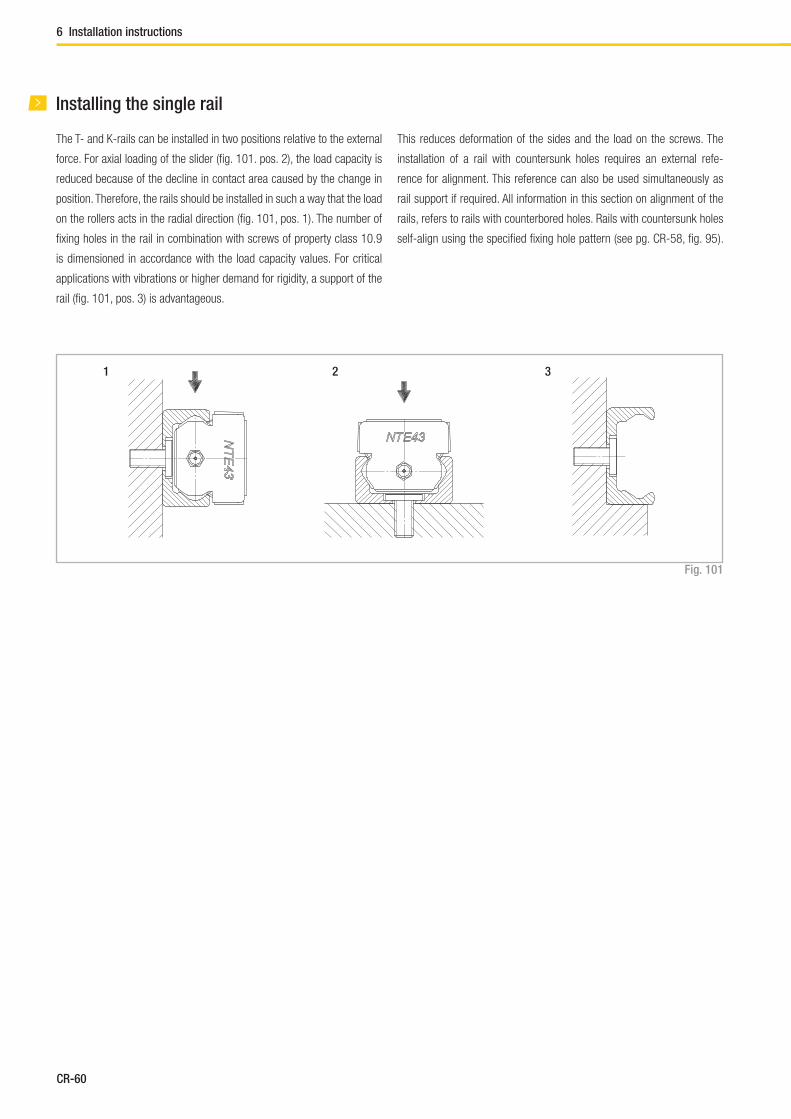
CR-60
6 Installation instructions
Installing the single rail
The T- and K-rails can be installed in two positions relative to the external
force. For axial loading of the slider (fi g. 101. pos. 2), the load capacity is
reduced because of the decline in contact area caused by the change in
position. Therefore, the rails should be installed in such a way that the load
on the rollers acts in the radial direction (fi g. 101, pos. 1). The number of
fi xing holes in the rail in combination with screws of property class 10.9
is dimensioned in accordance with the load capacity values. For critical
applications with vibrations or higher demand for rigidity, a support of the
rail (fi g. 101, pos. 3) is advantageous.
This reduces deformation of the sides and the load on the screws. The
installation of a rail with countersunk holes requires an external refe-
rence for alignment. This reference can also be used simultaneously as
rail support if required. All information in this section on alignment of the
rails, refers to rails with counterbored holes. Rails with countersunk holes
self-align using the specifi ed fi xing hole pattern (see pg. CR-58, fi g. 95 ).
Fig. 101
1 2 3
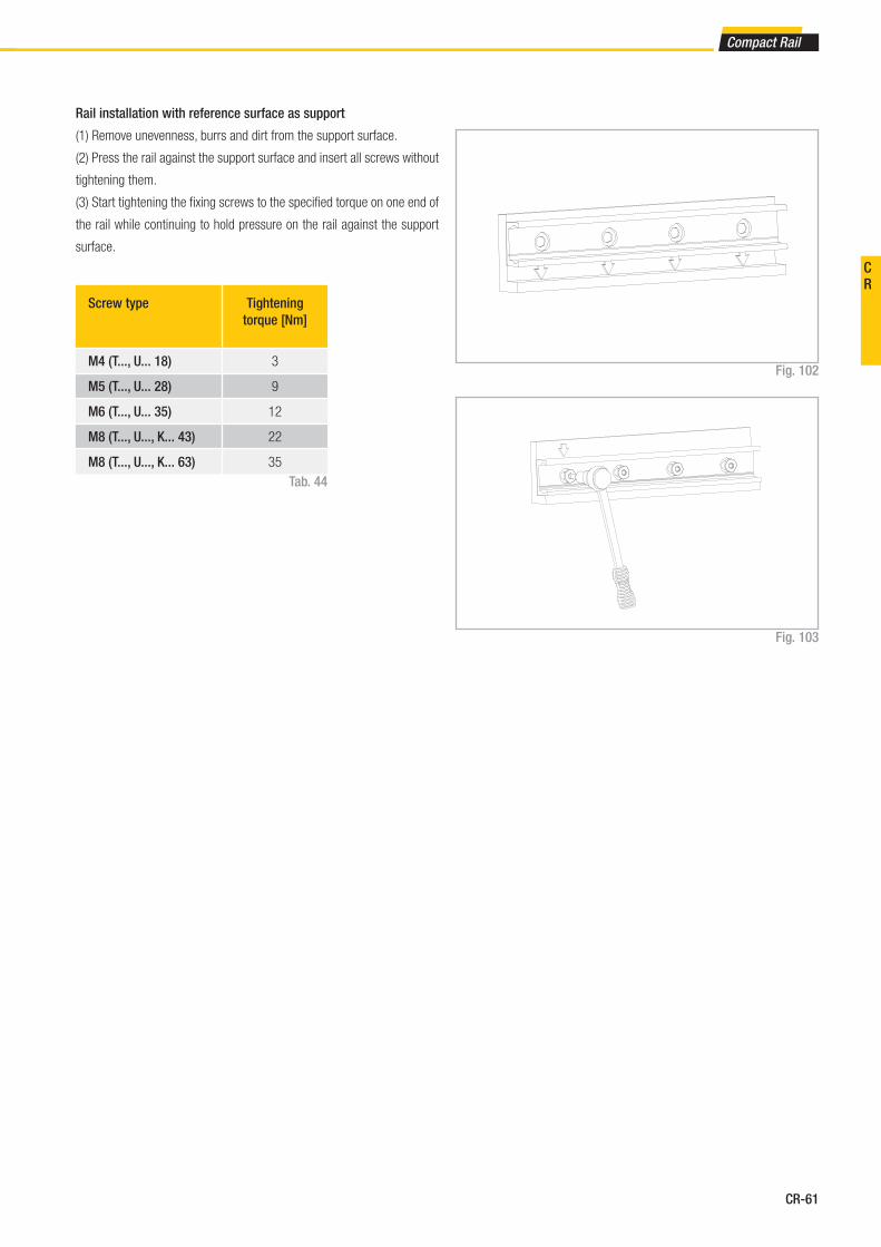
CR-61
Compact Rail
Fig. 102
Rail installation with reference surface as support
(1) Remove unevenness, burrs and dirt from the support surface.
(2) Press the rail against the support surface and insert all screws without
tightening them.
(3) Start tightening the fi xing screws to the specifi ed torque on one end of
the rail while continuing to hold pressure on the rail against the support
surface.
Screw type Tightening
torque [Nm]
M4 (T..., U... 18) 3
M5 (T..., U... 28) 9
M6 (T..., U... 35) 12
M8 (T..., U..., K... 43) 22
M8 (T..., U..., K... 63) 35
Tab. 44
Fig. 103
CR
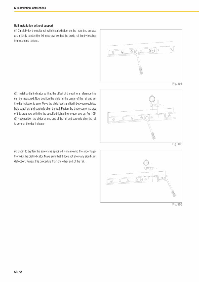
CR-62
6 Installation instructions
Fig. 104
Fig. 105
Fig. 106
Rail installation without support
(1) Carefully lay the guide rail with installed slider on the mounting surface
and slightly tighten the fi xing screws so that the guide rail lightly touches
the mounting surface.
(2) Install a dial indicator so that the offset of the rail to a reference line
can be measured. Now position the slider in the center of the rail and set
the dial indicator to zero. Move the slider back and forth between each two
hole spacings and carefully align the rail. Fasten the three center screws
of this area now with the the specifi ed tightening torque, see pg. fi g. 105.
(3) Now position the slider on one end of the rail and carefully align the rail
to zero on the dial indicator.
(4) Begin to tighten the screws as specifi ed while moving the slider toge-
ther with the dial indicator. Make sure that it does not show any signifi cant
defl ection. Repeat this procedure from the other end of the rail.

CR-63
Compact Rail
If two T-rails or a T+U-system are installed, the height difference of the two
rails must not exceed a certain value (obtainable from the table below) in
order to ensure proper guiding. These maximum values result from the ma-
ximum allowable twisting angle of the rollers in the raceways (see tab. 45).
These values account for a load capacity reduction of 30% on the T-rail
and must absolutely be maintained in every case.
Size α
18 1 mrad (0.057°)
28 2.5 mrad (0.143°)
35 2.6 mrad (0.149°)
43 3 mrad (0.171°)
63 5 mrad (0.286°)
Tab. 45
Fig. 107
Example:
NTE43: if a = 500 mm; b= a*tanα = 1.5 mm
When using two T-rails, the maximum parallelism deviation must not be
exceeded (see tab. 46). Otherwise stresses can occur, which can result in
a reduction in load capacity and service life.
Rail size K1 K2
18 0.03 0.02
28 0.04 0.03
35 0.04 0.03
43 0.05 0.04
63 0.06 0.05
Tab. 46
Fig. 108
Note: For parallelism problems, it is recommended to use a T+U or
K+U system, since these combinations compensate for inaccuracies
(see pg. CR-40, or CR-42 ).
Parallel installation of two rails
a
bα
CR
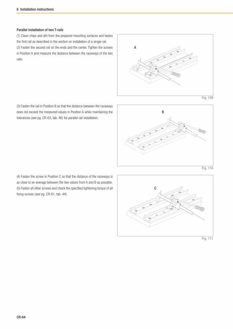
CR-64
6 Installation instructions
(1) Clean chips and dirt from the prepared mounting surfaces and fasten
the fi rst rail as described in the section on installation of a single rail.
(2) Fasten the second rail on the ends and the center. Tighten the screws
in Position A and measure the distance between the raceways of the two
rails.
Fig. 109
Fig. 110
Fig. 111
Parallel installation of two T-rails
(3) Fasten the rail in Position B so that the distance between the raceways
does not exceed the measured values in Position A while maintaining the
tolerances (see pg. CR-63, tab. 46 ) for parallel rail installation.
(4) Fasten the screw in Position C so that the distance of the raceways is
as close to an average between the two values from A and B as possible.
(5) Fasten all other screws and check the specifi ed tightening torque of all
fi xing screws ( see pg. CR-61, tab. 44).
A
B
C

CR-65
Compact Rail
When using a two-track parallel linear guide we recommend the use of a
fi xed bearing / compensating bearing system: The combination of T+U-
rails for compensation of deviations in parallelism or the K+U-system to
compensate for deviations in parallelism in two planes.
Installation of the T+U- or the K+U-system
Fig. 112
Fig. 113
Installation steps
(1) For a fi xed bearing / compensating bearing system the fi xed bearing
rail is always installed fi rst. This is then used as a reference for the com-
pensating bearing rail.
Then proceed as described in the section on installation of a single rail
(see pg. CR-60).
(2) Install the compensating bearing rail and only tighten the fi xing screws
slightly.
(3) Insert the sliders in the rails and install the element to be moved, wit-
hout tightening its screws.
(4) Insert the element in the center of the rails and tighten it with the
correct tightening torque (see pg. CR-59, tab. 42 ).
(5) Tighten the center rail fi xing screws to the specifi ed torque
(see fi g. 113).
(6) Move the element to one end of the rail and start tightening the rest of
the screws in the direction away from the slider.
Fig. 114
CR

CR-66
A A
A1 A1 A2 A2
B2B2B1 B1
6 Installation instructions
If long guide rails are required, two or more rails can be joined to the
desired length. When putting guide rails together, be sure that the register
marks shown in fi g. 115 are positioned correctly.
These are fabricated asymmetric for parallel application of joined guide
rails, unless otherwise specifi ed.
Fig. 115
Two rails
Several rails
Comp. L
Comp. L
Joint
Joint marks
Joint marks
Joint marks
Joint marks
Joint marks
Joint
Joint
Joint
Joint
Joined Rails
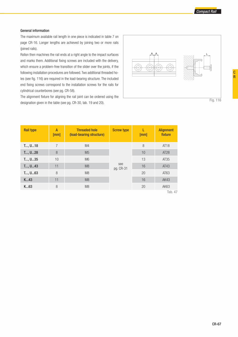
CR-67
Compact Rail
General information
The maximum available rail length in one piece is indicated in table 7 on
page CR-16. Longer lengths are achieved by joining two or more rails
(joined rails).
Rollon then machines the rail ends at a right angle to the impact surfaces
and marks them. Additional fi xing screws are included with the delivery,
which ensure a problem-free transition of the slider over the joints, if the
following installation procedures are followed. Two additional threaded ho-
les (see fi g. 116) are required in the load-bearing structure. The included
end fi xing screws correspond to the installation screws for the rails for
cylindrical counterbores (see pg. CR-58).
The alignment fi xture for aligning the rail joint can be ordered using the
designation given in the table (see pg. CR-30, tab. 19 and 20).Fig. 116
Rail type A
[mm]
Threaded hole
(load-bearing structure)
Screw type L
[mm]
Alignment
fi xture
T..., U...18 7 M4
see
pg. CR-31
8 AT18
T..., U...28 8 M5 10 AT28
T..., U...35 10 M6 13 AT35
T..., U...43 11 M8 16 AT43
T..., U...63 8 M8 20 AT63
K...43 11 M8 16 AK43
K...63 8 M8 20 AK63
Tab. 47
LA A
CR
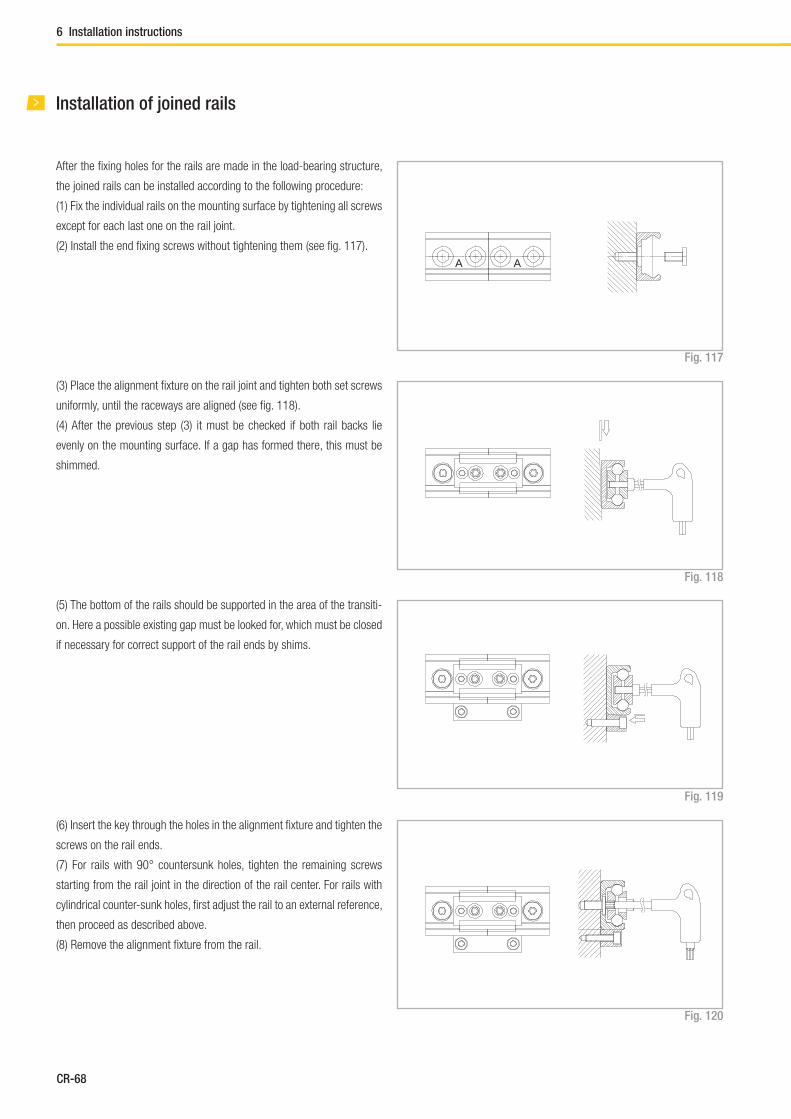
CR-68
6 Installation instructions
Installation of joined rails
After the fi xing holes for the rails are made in the load-bearing structure,
the joined rails can be installed according to the following procedure:
(1) Fix the individual rails on the mounting surface by tightening all screws
except for each last one on the rail joint.
(2) Install the end fi xing screws without tightening them (see fi g. 117).
Fig. 117
(3) Place the alignment fi xture on the rail joint and tighten both set screws
uniformly, until the raceways are aligned (see fi g. 118).
(4) After the previous step (3) it must be checked if both rail backs lie
evenly on the mounting surface. If a gap has formed there, this must be
shimmed.
(5) The bottom of the rails should be supported in the area of the transiti-
on. Here a possible existing gap must be looked for, which must be closed
if necessary for correct support of the rail ends by shims.
(6) Insert the key through the holes in the alignment fi xture and tighten the
screws on the rail ends.
(7) For rails with 90° countersunk holes, tighten the remaining screws
starting from the rail joint in the direction of the rail center. For rails with
cylindrical counter-sunk holes, fi rst adjust the rail to an external reference,
then proceed as described above.
(8) Remove the alignment fi xture from the rail.
A A
Fig. 118
Fig. 119
Fig. 120

CR-69
Compact Rail
TLC 4560 /2/ CD W 28 -125 -2Z -B -NIC
Expanded surface pro-
tection if deviation from
Standard ISO 2081
see pg. CR-57
Confi guration depending on type of
slider see pgs. CR-20 and CR-23
Roller seal see pg. CR-29
Slider length Dimension A see pg. CR-16, tab. 8-11
Size see pg. CR-16
Wiper optional see pg. CR-30, fi g. 43
Slider type see pg. CR-16
Number of sliders in one rail
Rail length in mm see pg. CR-15, tab. 7
Rail type see pg. CR-12
Rail / slider system
Ordering example: TLC-04560/2/CDW28-125-2Z-B-NIC
Rail composition: 1x3280+1x1280 (only for joint processed rails)
Hole pattern: 40-40x80-40//40-15x80-40 (please always specify the hole pattern separately)
Notes on ordering: The rail length codes are always 5 digits, the slider length codes are always 3 digits; use zeroes as a prefi x when lengths are shorter
TLV -43 -5680 -NIC
Expanded surface protection if deviation from Standard ISO 2081 see pg. CR-57
Rail length in mm see pg. CR-15, table 7
Size see pg. CR-12
Rail type see pg. CR-12
Rail
Ordering example: TLV-43-05680-NIC
Rail composition: 1x880+2x2400 (only for joint processed rails)
Hole pattern: 40-10x80-40//40-29x80-40//40-29x80-40 (please always specify the hole pattern separately)
Notes on ordering: The rail length codes are always 5 digits; use zeroes as a prefi x when lengths are shorter
Ordering key
CR
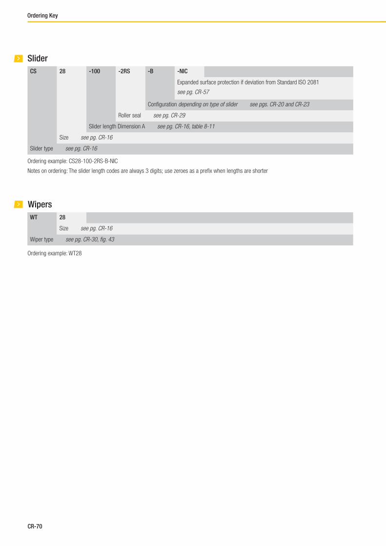
CR-70
Ordering Key
CS 28 -100 -2RS -B -NIC
Expanded surface protection if deviation from Standard ISO 2081
see pg. CR-57
Confi guration depending on type of slider see pgs. CR-20 and CR-23
Roller seal see pg. CR-29
Slider length Dimension A see pg. CR-16, table 8-11
Size see pg. CR-16
Slider type see pg. CR-16
Slider
Ordering example: CS28-100-2RS-B-NIC
Notes on ordering: The slider length codes are always 3 digits; use zeroes as a prefi x when lengths are shorter
WT 28
Size see pg. CR-16
Wiper type see pg. CR-30, fi g. 43
Wipers
Ordering example: WT28
CR-71
Compact Rail
Notes
CR

X-Rail
FrontespizioXRai.indd 1 07/10/2013 11:30:14
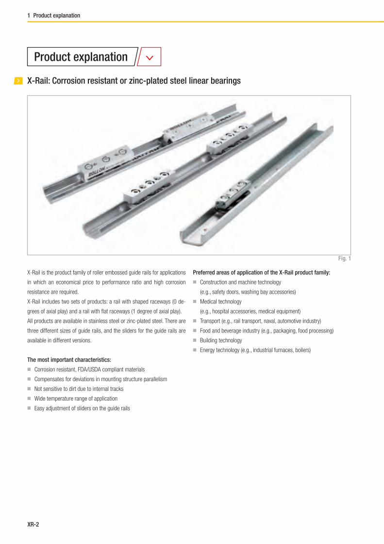
XR-2
X-Rail: Corrosion resistant or zinc-plated steel linear bearings
1 Product explanation
X-Rail is the product family of roller embossed guide rails for applications
in which an economical price to performance ratio and high corrosion
resistance are required.
X-Rail includes two sets of products: a rail with shaped raceways (0 de-
grees of axial play) and a rail with fl at raceways (1 degree of axial play).
All products are available in stainless steel or zinc-plated steel. There are
three different sizes of guide rails, and the sliders for the guide rails are
available in different versions.
The most important characteristics:
■ Corrosion resistant, FDA/USDA compliant materials
■ Compensates for deviations in mounting structure parallelism
■ Not sensitive to dirt due to internal tracks
■ Wide temperature range of application
■ Easy adjustment of sliders on the guide rails
Preferred areas of application of the X-Rail product family:
■ Construction and machine technology
(e.g., safety doors, washing bay accessories)
■ Medical technology
(e.g., hospital accessories, medical equipment)
■ Transport (e.g., rail transport, naval, automotive industry)
■ Food and beverage industry (e.g., packaging, food processing)
■ Building technology
■ Energy technology (e.g., industrial furnaces, boilers)
Fig. 1
Product explanation
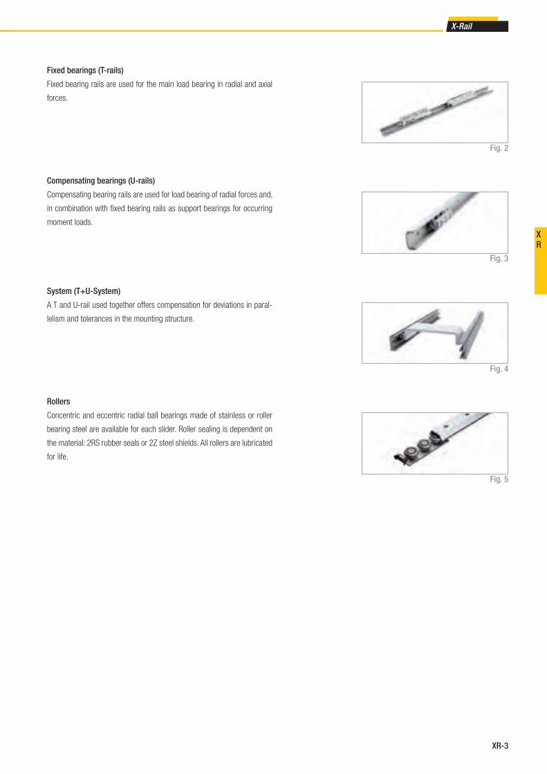
XR-3
X-Rail
XR
Fixed bearings (T-rails)
Fixed bearing rails are used for the main load bearing in radial and axial
forces.
System (T+U-System)
A T and U-rail used together offers compensation for deviations in paral-
lelism and tolerances in the mounting structure.
Compensating bearings (U-rails)
Compensating bearing rails are used for load bearing of radial forces and,
in combination with fi xed bearing rails as support bearings for occurring
moment loads.
Rollers
Concentric and eccentric radial ball bearings made of stainless or roller
bearing steel are available for each slider. Roller sealing is dependent on
the material: 2RS rubber seals or 2Z steel shields. All rollers are lubricated
for life.
Fig. 2
Fig. 3
Fig. 4
Fig. 5
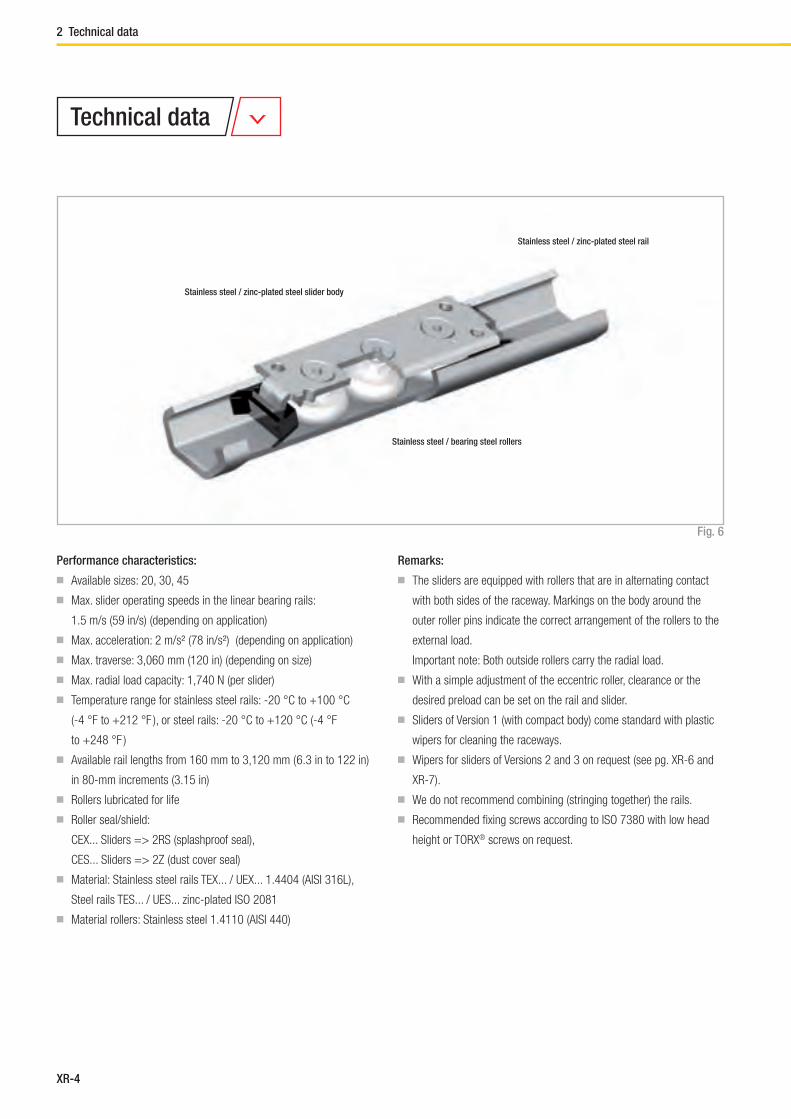
XR-4
2 Technical data
Stainless steel / zinc-plated steel slider body
Stainless steel / bearing steel rollers
Stainless steel / zinc-plated steel rail
Performance characteristics:
■ Available sizes: 20, 30, 45
■ Max. slider operating speeds in the linear bearing rails:
1.5 m/s (59 in/s) (depending on application)
■ Max. acceleration: 2 m/s² (78 in/s²) (depending on application)
■ Max. traverse: 3,060 mm (120 in) (depending on size)
■ Max. radial load capacity: 1,740 N (per slider)
■ Temperature range for stainless steel rails: -20 °C to +100 °C
(-4 °F to +212 °F ), or steel rails: -20 °C to +120 °C (-4 °F
to +248 °F )
■ Available rail lengths from 160 mm to 3,120 mm ( 6.3 in to 122 in)
in 80-mm increments (3.15 in)
■ Rollers lubricated for life
■ Roller seal/shield:
CEX... Sliders => 2RS (splashproof seal),
CES... Sliders => 2Z (dust cover seal)
■ Material: Stainless steel rails TEX... / UEX... 1.4404 (AISI 316L),
Steel rails TES... / UES... zinc-plated ISO 2081
■ Material rollers: Stainless steel 1.4110 (AISI 440)
Remarks:
■ The sliders are equipped with rollers that are in alternating contact
with both sides of the raceway. Markings on the body around the
outer roller pins indicate the correct arrangement of the rollers to the
external load.
Important note: Both outside rollers carry the radial load.
■ With a simple adjustment of the eccentric roller, clearance or the
desired preload can be set on the rail and slider.
■ Sliders of Version 1 (with compact body) come standard with plastic
wipers for cleaning the raceways.
■ Wipers for sliders of Versions 2 and 3 on request (see pg. XR-6 and
XR-7).
■ We do not recommend combining (stringing together) the rails.
■ Recommended fi xing screws according to ISO 7380 with low head
height or TORX® screws on request.
Fig. 6
Technical data

XR-5
X-Rail
XR
Compensating bearings
Confi guration C0rad
[N]
UEX-20 – CEXU20 300
UEX-30 – CEXU30 800
UEX-45 – CEXU45 1600
UES-20 – CESU20 326
UES-30 – CESU30 870
UES-45 – CESU45 1740
Confi guration C0rad
[N]
C0ax
[N]
TEX-20 – CEX20 300 170
TEX-30 – CEX30 800 400
TEX-45 – CEX45 1600 860
TES-20 – CES20 326 185
TES-30 – CES30 870 435
TES-45 – CES45 1740 935
Resulting moment loads must be absorbed
through the use of two sliders
Fixed bearings
Load capacities
C0rad
C0rad
C0ax
Fig. 7
Fig. 8
Tab. 1
Tab. 2

XR-6
3 Product dimensions
Rail type Size A
[mm]
B
[mm]
C
[mm]
D
[mm]
E
[mm]
F
[mm]
G
[mm]
H
[mm]
Holes for
screws
Weight
[kg/m]
TEX
TES
20 19.2 10 2 7 3 7 4.5 2 M4 0.47
30 29.5 15 2.5 10 4.5 8.4 6.4 2 M5 0.90
45 46.4 24 4 15.5 6.5 11 9 2 M8 2.29
Fixed rails
Please specify hole pattern separately
Special lengths or pitches available upon request, please contact the sales department
The highlighted rail lenghts are available from stock
L
40 80 (Hole pitch) 40
A
B
C
E
D
H
G
F
Rail (TEX = stainless steel / TES = zinc-plated steel)
Rail type Standard length L
[mm]
TEX
TES
160 - 240 - 320 - 400 - 480 - 560 - 640 - 720 - 800 - 880 - 960
- 1040 - 1120 - 1200 - 1280 - 1360 - 1440 - 1520 - 1600 - 1680
- 1760 - 1840 - 1920 - 2000 - 2080 - 2160 - 2240 - 2320 - 2400
- 2480 - 2560 - 2640 - 2720 - 2800 - 2880 - 2960 - 3040 - 3120
Fig. 9
Tab. 3
Tab. 4
Product dimensions
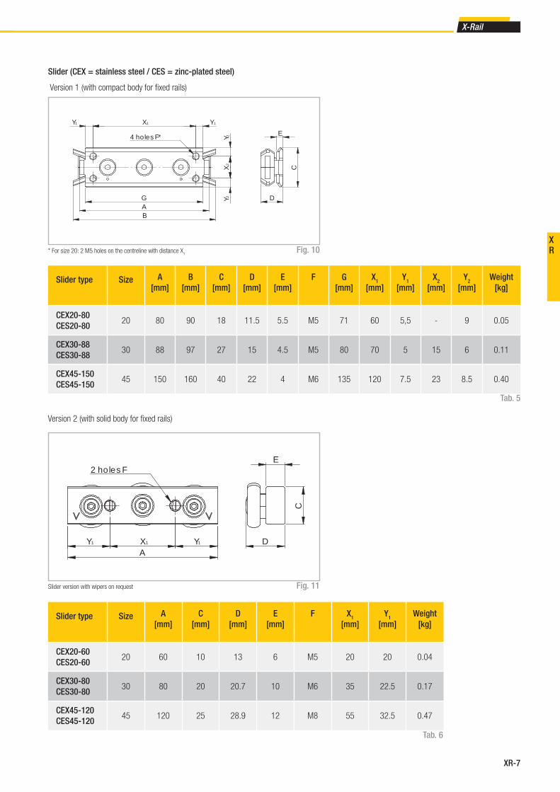
XR-7
X-Rail
XR
Slider type Size A
[mm]
B
[mm]
C
[mm]
D
[mm]
E
[mm]
F G
[mm]
X1
[mm]
Y1
[mm]
X2
[mm]
Y2
[mm]
Weight
[kg]
CEX20-80
CES20-8020 80 90 18 11.5 5.5 M5 71 60 5,5 - 9 0.05
CEX30-88
CES30-8830 88 97 27 15 4.5 M5 80 70 5 15 6 0.11
CEX45-150
CES45-15045 150 160 40 22 4 M6 135 120 7.5 23 8.5 0.40
Slider (CEX = stainless steel / CES = zinc-plated steel)
Version 1 (with compact body for fi xed rails)
* For size 20: 2 M5 holes on the centreline with distance X1
GAB
YXY
XY
Y
4 holes F*
D
E
C
11 1
22
2
Slider type Size A
[mm]
C
[mm]
D
[mm]
E
[mm]
F X1
[mm]
Y1
[mm]
Weight
[kg]
CEX20-60
CES20-6020 60 10 13 6 M5 20 20 0.04
CEX30-80
CES30-8030 80 20 20.7 10 M6 35 22.5 0.17
CEX45-120
CES45-12045 120 25 28.9 12 M8 55 32.5 0.47
Version 2 (with solid body for fi xed rails)
AY X Y
2 holes FE
C
D1 1 1
Slider version with wipers on request
Fig. 10
Fig. 11
Tab. 5
Tab. 6

XR-8
3 Product dimensions
Compensating rails
A
B
C
E
L
40 80 (Hole pitch) 40
F
GH
Rail type Size A
[mm]
B
[mm]
C
[mm]
E
[mm]
F
[mm]
G
[mm]
H
[mm]
Holes for
screws
Weight
[kg/m]
UEX UES20 20.5 11 3 5.5 7 4.5 2 M4 0.77
30 31.8 16 4 7 8.4 6.4 2 M5 1.39
UES 45 44.8 24.5 4.5 9.5 11 9 2 M8 2.79
UEX 45 43.8 24.5 4 9.5 11 9 2 M8 2.48
Rail (UEX = stainless steel / UES = zinc-plated steel)
Rail type Standard length L
[mm]
UEX
UES
160 - 240 - 320 - 400 - 480 - 560 - 640 - 720 - 800 - 880 - 960
- 1040 - 1120 - 1200 - 1280 - 1360 - 1440 - 1520 - 1600 - 1680
- 1760 - 1840 - 1920 - 2000 - 2080 - 2160 - 2240 - 2320 - 2400
- 2480 - 2560 - 2640 - 2720 - 2800 - 2880 - 2960 - 3040 - 3120
Please specify hole pattern separately
Special lengths or pitches available upon request, please contact the sales department
The highlighted rail lenghts are available from stock
Fig. 12
Tab. 7
Tab. 8

XR-9
X-Rail
XR
Slider (CEXU = stainless steel / CESU = zinc-plated steel)
Version 3 (with solid body for compensating rail)
Slider type Size A
[mm]
C
[mm]
D
[mm]
E
[mm]
F
[mm]
X1
[mm]
Y1
[mm]
Weight
[kg]
CEXU20-60
CESU20-6020 60 10 11.85 6 M5 20 20 0.04
CEXU30-80
CESU30-8030 80 20 19.9 10 M6 35 22.5 0.16
CEXU45-120
CESU45-12045 120 25 26.4 12 M8 55 32.5 0.45
A
Y X Y
2 holes F
D
C
E
1 11
Slider version with wipers on request Fig. 13
Tab. 9

XR-10
3 Product dimensions
Compensating rails
B
C
D
A
nom
Fig. 16
Tab. 12
Fixed rails
Version 1
(Slider with compact body)
Version 2
(Slider with solid body)
A
BC
D
A
B
C
D
Confi guration A
[mm]
B
[mm]
C
[mm]
D
[mm]
TEX-20 – CEX20-80
TES-20 – CES20-8019.2 16 18 2.5
TEX-30 – CEX30-88
TES-30 – CES30-8829.5 20.5 27 3.5
TEX-45 – CEX45-150
TES-45 – CES45-15046.4 31 40 5
Confi guration A
[mm]
B
[mm]
C
[mm]
D
[mm]
TEX-20 – CEX20-60
TES-20 – CES20-6019.2 17.8 10 2.6
TEX-30 – CEX30-80
TES-30 – CES30-8029.5 26.5 20 3.3
TEX-45 – CEX45-120
TES-45 – CES45-12046.4 38 25 5.1
Fig. 14
Fig. 15
Tab. 10
Tab. 11
Mounted sliders and rails
Version 3
(Slider with solid body)
Confi guration A
[mm]
Bnom
[mm]
C
[mm]
D
[mm]
UEX-20 – CEXU20-60
UES-20 – CESU20-6020.5 18.25 ± 0.6 10 3.4
UEX-30 – CEXU30-80
UES-30 – CESU30-8031.8 27.95 ± 1.0 20 4.05
UEX-45 – CEXU45-120
UES-45 – CESU45-12044.8 37.25 ± 1.75 25 6.35
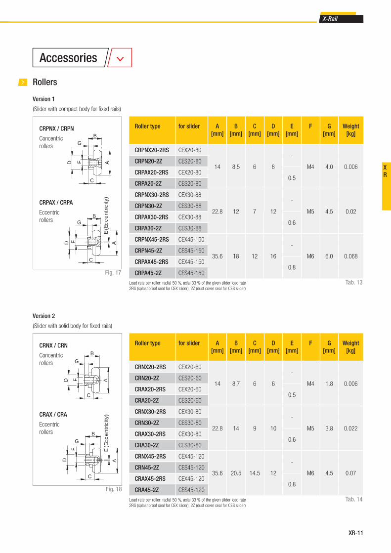
XR-11
X-Rail
XR
Roller type for slider A
[mm]
B
[mm]
C
[mm]
D
[mm]
E
[mm]
F G
[mm]
Weight
[kg]
CRPNX20-2RS CEX20-80
14 8.5 6 8
-
M4 4.0 0.006CRPN20-2Z CES20-80
CRPAX20-2RS CEX20-800.5
CRPA20-2Z CES20-80
CRPNX30-2RS CEX30-88
22.8 12 7 12
-
M5 4.5 0.02CRPN30-2Z CES30-88
CRPAX30-2RS CEX30-880.6
CRPA30-2Z CES30-88
CRPNX45-2RS CEX45-150
35.6 18 12 16
-
M6 6.0 0.068CRPN45-2Z CES45-150
CRPAX45-2RS CEX45-1500.8
CRPA45-2Z CES45-150
Rollers
Version 1
(Slider with compact body for fi xed rails)
CRPNX / CRPN
Concentric
rollers
CRPAX / CRPA
Eccentric
rollers
CRNX / CRN
Concentric
rollers
CRAX / CRA
Eccentric
rollers
Version 2
(Slider with solid body for fi xed rails)
Load rate per roller: radial 50 %, axial 33 % of the given slider load rate
2RS (splashproof seal for CEX slider), 2Z (dust cover seal for CES slider)
Roller type for slider A
[mm]
B
[mm]
C
[mm]
D
[mm]
E
[mm]
F G
[mm]
Weight
[kg]
CRNX20-2RS CEX20-60
14 8.7 6 6
-
M4 1.8 0.006CRN20-2Z CES20-60
CRAX20-2RS CEX20-600.5
CRA20-2Z CES20-60
CRNX30-2RS CEX30-80
22.8 14 9 10
-
M5 3.8 0.022CRN30-2Z CES30-80
CRAX30-2RS CEX30-800.6
CRA30-2Z CES30-80
CRNX45-2RS CEX45-120
35.6 20.5 14.5 12
-
M6 4.5 0.07CRN45-2Z CES45-120
CRAX45-2RS CEX45-1200.8
CRA45-2Z CES45-120
Load rate per roller: radial 50 %, axial 33 % of the given slider load rate
2RS (splashproof seal for CEX slider), 2Z (dust cover seal for CES slider)
Fig. 17
Fig. 18
Tab. 13
Tab. 14
A
B
D
E (E
cc
en
tric
ity)
G
C
F
A
B
D
G
F
C
A
B
C
D
F
G
E (E
cc
en
tric
ity)
A
B
C
FD
G
Accessories
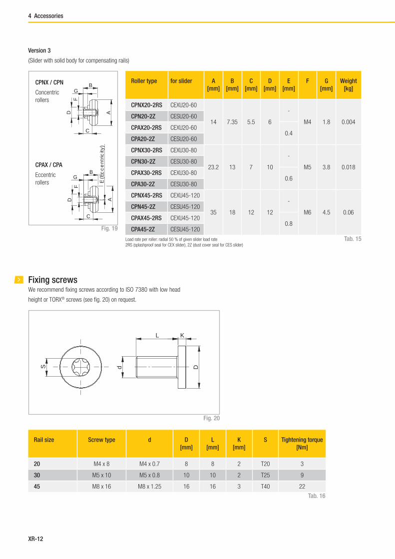
XR-12
Roller type for slider A
[mm]
B
[mm]
C
[mm]
D
[mm]
E
[mm]
F G
[mm]
Weight
[kg]
CPNX20-2RS CEXU20-60
14 7.35 5.5 6
-
M4 1.8 0.004CPN20-2Z CESU20-60
CPAX20-2RS CEXU20-600.4
CPA20-2Z CESU20-60
CPNX30-2RS CEXU30-80
23.2 13 7 10
-
M5 3.8 0.018CPN30-2Z CESU30-80
CPAX30-2RS CEXU30-800.6
CPA30-2Z CESU30-80
CPNX45-2RS CEXU45-120
35 18 12 12
-
M6 4.5 0.06CPN45-2Z CESU45-120
CPAX45-2RS CEXU45-1200.8
CPA45-2Z CESU45-120
Version 3
(Slider with solid body for compensating rails)
Load rate per roller: radial 50 % of given slider load rate
2RS (splashproof seal for CEX slider), 2Z (dust cover seal for CES slider)
CPNX / CPN
Concentric
rollers
CPAX / CPA
Eccentric
rollers
Fixing screwsWe recommend fi xing screws according to ISO 7380 with low head
height or TORX® screws (see fi g. 20) on request.
S d
L K
D
Rail size Screw type d D
[mm]
L
[mm]
K
[mm]
S Tightening torque
[Nm]
20 M4 x 8 M4 x 0.7 8 8 2 T20 3
30 M5 x 10 M5 x 0.8 10 10 2 T25 9
45 M8 x 16 M8 x 1.25 16 16 3 T40 22
Fig. 19
Fig. 20
Tab. 15
Tab. 16
AD
GB
C
F
A
B
D
E (E
cc
en
tric
ity)
G
C
F
4 Accessories

XR-13
X-Rail
XR
T+U-System
Solves axial deviations in parallelism
Mounting two linear bearing rails in a parallel manner is always important
but rarely easy. Distortions in axial alignment can drastically reduce the
life of the rails. These distortions can bind and overload sliders. Rollon
offers an outstanding solution for the alignment of dual track carriages.
Using shaped and fl at raceways it is possible to avoid axial deviation in
parallelism of the mounting surfaces without additional modifi cations of
those surfaces. T+U rails easily address these alignment issues to create
an economical parallel rail system.
In a T+U-System, the slider in the T rail carries axial and radial loads and
guides the movement of the U, which has lateral freedom.
U rails have fl at parallel raceways that allow free lateral movement of
the sliders. The maximum freedom a slider in the U rail can offer can be
calculated using the values S1 and S
2 (see pg. XR-14, fi g. 22, tab. 19).
With nominal value Bnom
as the starting point, S1 indicates the maximum
allowed movement into the rail, while S2 represents the maximum offset
towards the outside of the rail.
If the length of the guide rail is known, the maximum allowable angle de-
viation of the mounting surface (see pg. XR-14, fi g. 23) can be obtained.
In this case the slide in the U rail has the freedom to travel from the inner-
most position S1 to the outermost position S
2.
Fig. 21
LubricationAll radial ball bearing rollers in the X-Rail series are lubricated for life. It
is advisable to lubricate the raceways with specifi c bearing grease. The
interval between lubrication treatments depends mainly on environmental
conditions, bearing speed and temperature.
Under normal conditions, it is advisable to lubricate locally after 100 km of
use or after six months of service. In case of critical applications, lubrica-
tion treatments should be more frequent. Before lubricating, remember to
clean the raceway surfaces carefully. We advise using a lithium grease of
medium consistency for rolling-element bearings.
Different lubricants are available on request for special applications:
■ FDA-approved lubricant for use in the food industry
Technical instructions
■ specifi c lubricant for clean rooms
■ specifi c lubricant for the marine technology sector
■ specifi c lubricant for high and low temperatures
For specifi c information, contact Rollon technical support.
Under normal conditions, correct lubrication:
■ reduces friction
■ reduces wear
■ reduces stress on contact surfaces due to elastic deformation
■ reduces noise during operation
■ increases the regularity of the rolling movement

XR-14
Size Rail length
[mm]
Offset S*
[mm]
Angle α[°]
20 3120 1.2 0.022
30 3120 2 0.037
45 3120 3.5 0.064
Slider type
(Version 3 with solid body)
S1
[mm]
S2
[mm]
Bmin
[mm]
Bnom
[mm]
Bmax
[mm]
CEXU.../CESU20-60 0.6 0.6 17.65 18.25 18.85
CEXU.../CESU30-80 1 1 26.95 27.95 28.95
CEXU.../CESU45-120 1.75 1.75 35.50 37.25 39
S* = sum of S1 and S
2
L = length of the railα = arctan ––
S*
L
Guideline for the maximum angle deviation α, achievable with the
longest guide rail
Maximum offset
a
S
L
a
S
L
Fig. 22
Fig. 23
Fig. 24
Tab. 17
Tab. 18
Minimum position Nominal position Maximum position
5 Technical instructions

XR-15
X-Rail
XR
Setting preload
If the product is delivered with the sliders in the rails, the sliders are alrea-
dy preloaded. If delivered separately, or if the sliders need to be installed
in another rail, the sliders must be readjusted. In this case, follow the
instructions below:
■ Wipe the raceways of any dirt and debris.
■ If necessary, remove existing wipers and insert the sliders into the rails.
Slightly loosen the fi xing screw of the center roller pin.
■ Position the slider(s) at the ends of the rail.
■ For the U rails there must be a thin support (e.g. set key) under the
ends of the slider body to ensure the horizontal alignment of the slider
in the fl at raceways.
■ The included special fl at key is inserted from the side between the rail
and the slider and inserted onto the hexagonal or square shaft of the
eccentric pin to be adjusted (see fi g. 25).
■ By turning the fl at key clockwise, the eccentric roller is pressed against
the upper raceway, thereby removing clearance and setting the correct
preload. During this process, absence of play is desired; avoid setting
a preload that is so high that it generates high friction and reduces
service life.
■ Hold the roller with the adjustment key in the desired position and
carefully tighten the fi xing screw. The exact tightening torque will be
checked later.
■ Move the slider in the rail and check the preload over the entire length
of the rail. It should move easily and the slider should not have play at
any location of the rail.
■ Tighten the fi xing screw with the specifi ed tightening torque (see
tab. 19), while holding the fl at key and maintaining the angle position
of the roller so as to not change the preload while tightening the screw.
It is recommended to use thread locking compound.
■ Now re-attach the existing wipers if desired.
Size Tightening torque
[Nm]
20 3
30 7
45 12
Fig. 25
Tab. 19
If purchasing "Radial ball bearing rollers" to install on your own structure
(see from p. XR-10 to XR-12) we advise:
■ Using a maximum of 2 concentric radial ball bearing rollers
Use of radial ball bearing rollers
Fig. 26
Fig. 27
Slider size X
[mm]
20 0,60
30 0,65
45 0,60
Tab. 20
X
X
Midpoint lineSeats of concentric radial ball bearing rollers
Seat of eccentric radial ball bearing roller
Concentric radial ball bearing rollers
Eccentric radial ball bearing roller
Eccentrics
Eccentrics
■ Offset the seats of the concentric radial ball bearing rollers with
respect to those of the eccentric radial ball bearing rollers according to
the table (tab. 20).

XR-16
Ordering key
TEX- 960 /1/ CEX20-60 -2RS
Roller seal see pg. XR-4 Performance characteristics
Slider type see pg. XR-7, tab. 5 and 6/ pg. XR-9, tab. 9
Number of sliders in one rail
Rail length in mm see pg. XR-6, tab. 4 / pg.XR-8, tab. 8
Rail type see pg. XR-6, tab. 3 / pg. XR-8, tab. 7
Rail / slider system
TEX- 30- 960
Rail length in mm see pg. XR-6, tab. 4 / pg. XR-8, tab. 8
Size see pg. XR-6, tab. 3 / pg. XR-8, tab. 7
Rail type see pg. XR-6, tab. 5 / pg.XR-8, tab. 7
Rail
Slider
CES30-80 -2Z
Roller seal see pg. XR-6 Performance characteristics
Slider type see pg. XR-7, tab. 5 and 6/ pg. XR-9, tab. 9
Ordering example: TEX-00960/1/CEX20-060-2RS
Hole pitch: 40-11 x 80-40
Notes on ordering: The rail length codes are always 5 digits, the slider length codes are always 3 digits; use zeroes as a prefi x when lengths are shorter
Ordering example: TEX-30-00960
Hole pattern: 40-11 x 80-40
Notes on ordering: The rail length codes are always 5 digits; use zeroes as a prefi x when lengths are shorter
Ordering example: CES30-080-2Z
Notes on ordering: The slider length codes are always 3 digits; use zeroes as a prefi x when lengths are shorter
Ordering key
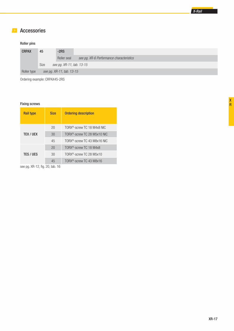
XR-17
X-Rail
XR
Accessories
Roller pins
CRPAX 45 -2RS
Roller seal see pg. XR-6 Performance characteristics
Size see pg. XR-11, tab. 13-15
Roller type see pg. XR-11, tab. 13-15
Fixing screws
Rail type Size Ordering description
TEX / UEX
20 TORX®-screw TC 18 M4x8 NIC
30 TORX®-screw TC 28 M5x10 NIC
45 TORX®-screw TC 43 M8x16 NIC
TES / UES
20 TORX®-screw TC 18 M4x8
30 TORX®-screw TC 28 M5x10
45 TORX®-screw TC 43 M8x16
Ordering example: CRPAX45-2RS
see pg. XR-12, fi g. 20, tab. 16

Easyslide
FrontespizioEasyslide.indd 1 21/05/2014 21:26:17
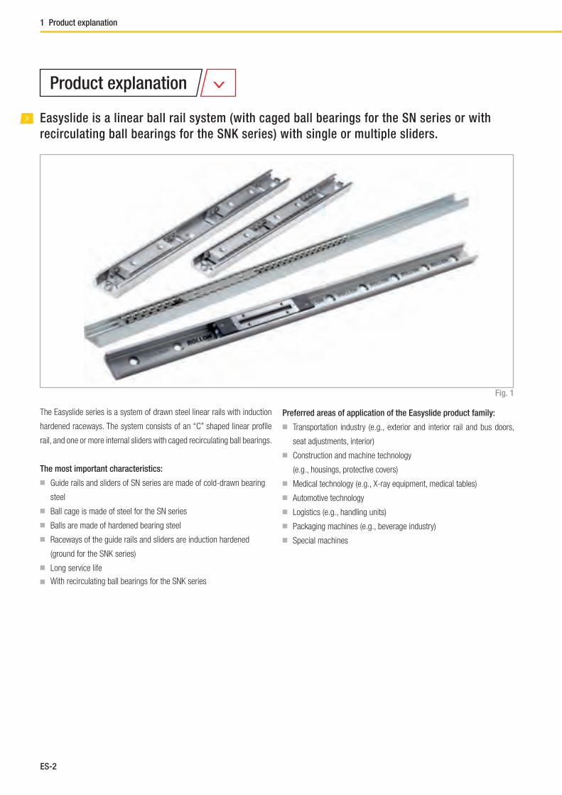
ES-2
Easyslide is a linear ball rail system (with caged ball bearings for the SN series or with
recirculating ball bearings for the SNK series) with single or multiple sliders.
1 Product explanation
The Easyslide series is a system of drawn steel linear rails with induction
hardened raceways. The system consists of an “C” shaped linear profi le
rail, and one or more internal sliders with caged recirculating ball bearings.
The most important characteristics:
■ Guide rails and sliders of SN series are made of cold-drawn bearing
steel
■ Ball cage is made of steel for the SN series
■ Balls are made of hardened bearing steel
■ Raceways of the guide rails and sliders are induction hardened
(ground for the SNK series)
■ Long service life
■ With recirculating ball bearings for the SNK series
Preferred areas of application of the Easyslide product family:
■ Transportation industry (e.g., exterior and interior rail and bus doors,
seat adjustments, interior)
■ Construction and machine technology
(e.g., housings, protective covers)
■ Medical technology (e.g., X-ray equipment, medical tables)
■ Automotive technology
■ Logistics (e.g., handling units)
■ Packaging machines (e.g., beverage industry)
■ Special machines
Fig. 1
Product explanation
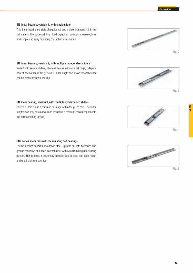
ES-3
Easyslide
ES
SN linear bearing, version 1, with single slider
This linear bearing consists of a guide rail and a slider that runs within the
ball cage in the guide rail. High load capacities, compact cross-sections
and simple and easy mounting characterize this series.
SN linear bearing, version 3, with multiple synchronized sliders
Several sliders run in a common ball cage within the guide rails. The slider
lengths can vary here as well and then form a total unit, which implements
the corresponding stroke.
SN linear bearing, version 2, with multiple independent sliders
Variant with several sliders, which each runs in its own ball cage, indepen-
dent of each other, in the guide rail. Slider length and stroke for each slider
can be different within one rail.
SNK series linear rails with recirculating ball bearings.
The SNK series consists of a drawn steel C profi le rail with hardened and
ground raceways and of an internal slider with a recirculating ball bearing
system. This product is extremely compact and boasts high load rating
and great sliding properties.
Fig. 2
Fig. 3
Fig. 4
Fig. 5

ES-4
2 Technical data
Rail
Ball cage
Performance characteristics:
■ Available sizes for SN: 22, 28, 35, 43, 63
■ Sections available for the SNK series: 43
■ Inductive raceways hardened and ground for the SNK series
■ Rails and sliders are made of cold-drawn bearing steel
■ Balls are made of hardened bearing steel
■ Max. operating speed 1.5 m/s (SNK)
■ Temperature range: from -20 °C to +170 °C for the SN series
from -20° to 70° for the SNK series
■ Electrolytic zinc-plating as per ISO 2081; increased anticorrosive
protection on request (see Chapter 4, Technical instructions, pg. 16
Anticorrosive protection)
■ Linear accuracy 0.1 mm/m stroke
■ 2 different types of preload
Remarks:
■ SN can only be horizontally mounted, high performance SNK can be
horizontally and vertically mounted.
■ External stops are recommended
■ Fixing screws of property class 10.9 must be used for all linear
bearings
Fig. 6
Slider
Technical data
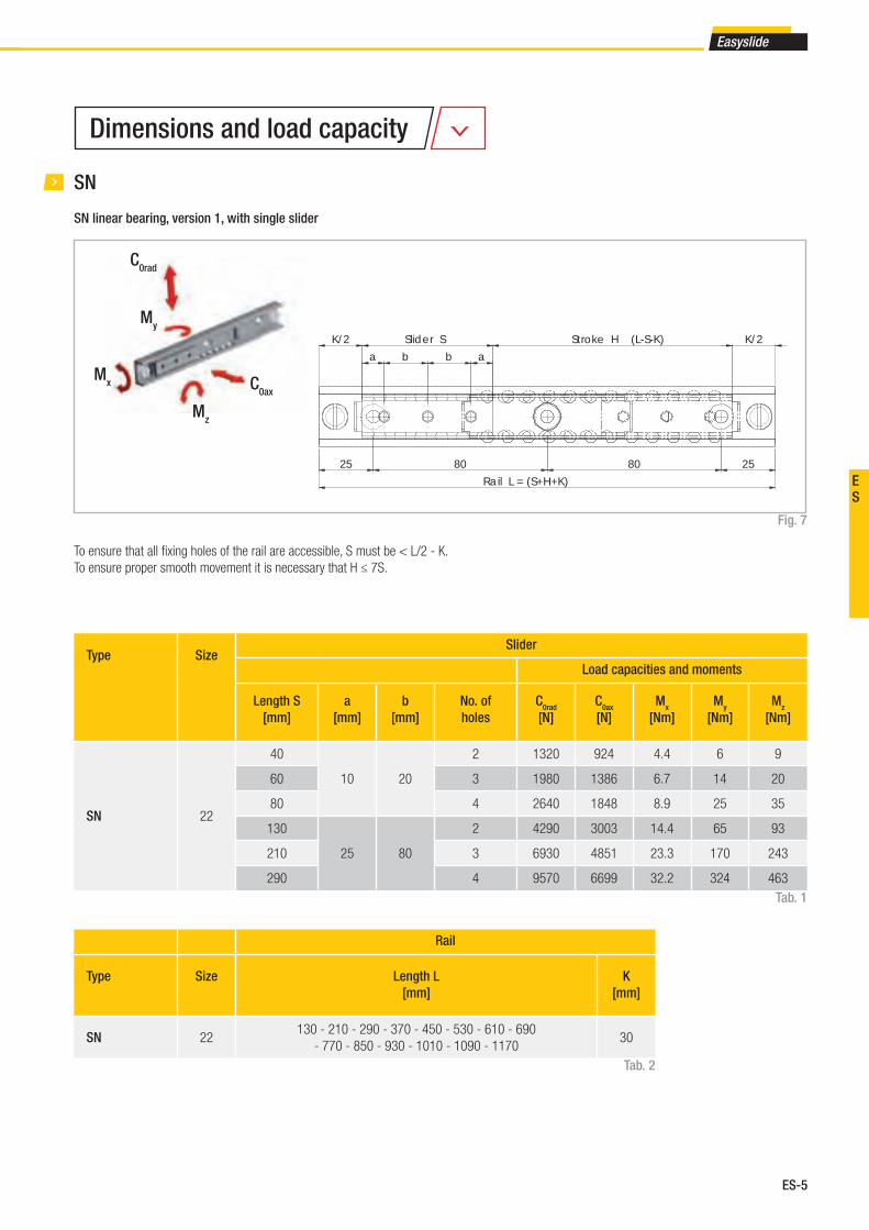
ES-5
Easyslide
ES
SN
SN linear bearing, version 1, with single slider
Fig. 7
Type SizeSlider
Load capacities and moments
Length S
[mm]
a
[mm]
b
[mm]
No. of
holes
C0rad
[N]
C0ax
[N]
Mx
[Nm]
My
[Nm]
Mz
[Nm]
SN 22
40
10 20
2 1320 924 4.4 6 9
60 3 1980 1386 6.7 14 20
80 4 2640 1848 8.9 25 35
130
25 80
2 4290 3003 14.4 65 93
210 3 6930 4851 23.3 170 243
290 4 9570 6699 32.2 324 463
Tab. 1
Rail
Type Size Length L
[mm]
K
[mm]
SN 22130 - 210 - 290 - 370 - 450 - 530 - 610 - 690
- 770 - 850 - 930 - 1010 - 1090 - 117030
Tab. 2
To ensure that all fi xing holes of the rail are accessible, S must be < L/2 - K.
To ensure proper smooth movement it is necessary that H ≤ 7S.
K/2 Slider S
a b b a
25 80 80 25
Rail L = (S+H+K)
Stroke H (L-S-K) K/2
C0rad
C0ax
Mz
My
Mx
Dimensions and load capacity
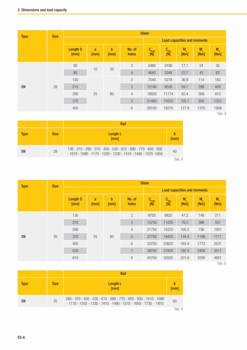
ES-6
3 Dimensions and load capacity
Tab. 5
Type SizeSlider
Load capacities and moments
Length S
[mm]
a
[mm]
b
[mm]
No. of
holes
C0rad
[N]
C0ax
[N]
Mx
[Nm]
My
[Nm]
Mz
[Nm]
SN 35
130
25 80
2 9750 6825 47.2 148 211
210 3 15750 11025 76.3 386 551
290 4 21750 15225 105.3 736 1051
370 5 27750 19425 134.4 1198 1711
450 6 33750 23625 163.4 1772 2531
530 7 39750 27825 192.5 2458 3511
610 8 45750 32025 221.6 3256 4651
Tab. 3
Type SizeSlider
Load capacities and moments
Length S
[mm]
a
[mm]
b
[mm]
No. of
holes
C0rad
[N]
C0ax
[N]
Mx
[Nm]
My
[Nm]
Mz
[Nm]
SN 28
6010 20
3 3480 2436 17.1 24 35
80 4 4640 3248 22.7 43 62
130
25 80
2 7540 5278 36.9 114 163
210 3 12180 8526 59.7 298 426
290 4 16820 11774 82.4 569 813
370 5 21460 15022 105.1 926 1323
450 6 26100 18270 127.9 1370 1958
Rail
Type Size Length L
[mm]
K
[mm]
SN 28130 - 210 - 290 - 370 - 450 - 530 - 610 - 690 - 770 - 850 - 930
- 1010 - 1090 - 1170 - 1250 - 1330 - 1410 - 1490 - 1570 -165040
Tab. 4
Rail
Type Size Length L
[mm]
K
[mm]
SN 35290 - 370 - 450 - 530 - 610 - 690 - 770 - 850 - 930 - 1010 - 1090
- 1170 - 1250 - 1330 - 1410 - 1490 - 1570 - 1650 - 1730 - 181050
Tab. 6

ES-7
Easyslide
ES
Tab. 7
Type SizeSlider
Load capacities and moments
Length S
[mm]
a
[mm]
b
[mm]
No. of
holes
C0rad
[N]
C0ax
[N]
Mx
[Nm]
My
[Nm]
Mz
[Nm]
SN 43
130
25 80
2 13910 9737 96 211 301
210 3 22470 15729 155.1 551 786
290 4 31030 21721 214.1 1050 1500
370 5 39590 27713 273.2 1709 2441
450 6 48150 33705 332.3 2528 3611
530 7 56710 39697 391.4 3507 5009
610 8 65270 45689 450.4 4645 6636
Tab. 9
Type SizeSlider
Load capacities and moments
Length S
[mm]
a
[mm]
b
[mm]
No. of
holes
C0rad
[N]
C0ax
[N]
Mx
[Nm]
My
[Nm]
Mz
[Nm]
SN 63
130
25 80
2 26000 18200 238.8 394 563
210 3 42000 29400 385.8 1029 1470
290 4 58000 40600 532.8 1962 2803
370 5 74000 51800 679.8 3194 4563
450 6 90000 63000 826.7 4725 6750
530 7 106000 74200 973.7 6554 9363
610 8 122000 85400 1120.7 8682 12403
Rail
Type Size Length L
[mm]
K
[mm]
SN 43
290 - 370 - 450 - 530 - 610 - 690 - 770 - 850 - 930
- 1010 - 1090 - 1170 - 1250 -1330 - 1410
- 1490 - 1570 - 1650 - 1730 - 1810 - 1890 - 1970
50
Tab. 8
Rail
Type Size Length L
[mm]
K*
[mm]
SN 63610 - 690 - 770 - 850 - 930 - 1010 - 1090 - 1170 - 1250
- 1330 - 1410 - 1490 - 1570 - 1650 - 1730 - 1810 - 1890 - 197080
Tab. 10* For systems of versions 2 in size 63 with two independent sliders, the K dimension changes from
80 mm to 110 mm and for each additional slider by another 30 mm
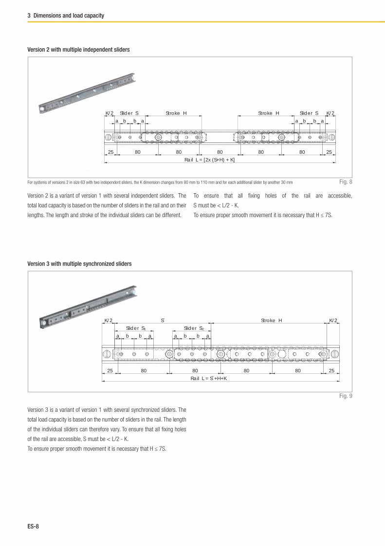
ES-8
Version 2 with multiple independent sliders
Fig. 8
Version 3 with multiple synchronized sliders
Fig. 9
Version 2 is a variant of version 1 with several independent sliders. The
total load capacity is based on the number of sliders in the rail and on their
lengths. The length and stroke of the individual sliders can be different.
Version 3 is a variant of version 1 with several synchronized sliders. The
total load capacity is based on the number of sliders in the rail. The length
of the individual sliders can therefore vary. To ensure that all fi xing holes
of the rail are accessible, S must be < L/2 - K.
To ensure proper smooth movement it is necessary that H ≤ 7S.
a b b a abba
K/2 Slider S Stroke H K/2Slider SStroke H
25 80 80 80 80 80 25
Rail L = [2x (S+H) + K]
K/2
a b b a
Slider S
a b b a
Slider S
S´ Stroke H K/2
25 80 80 80 80 25
Rail L = S´+H+K
1 2
To ensure that all fi xing holes of the rail are accessible,
S must be < L/2 - K.
To ensure proper smooth movement it is necessary that H ≤ 7S.
For systems of versions 2 in size 63 with two independent sliders, the K dimension changes from 80 mm to 110 mm and for each additional slider by another 30 mm
3 Dimensions and load capacity
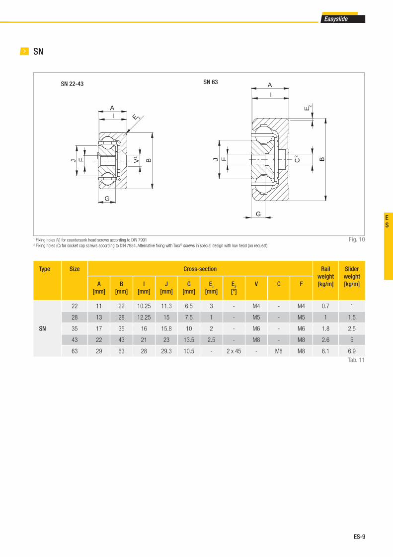
ES-9
Easyslide
ES
I
A
BC2
GJ
E 2
F
SN
Fig. 10
Type Size Cross-section Rail
weight
[kg/m]
Slider
weight
[kg/m]A
[mm]
B
[mm]
I
[mm]
J
[mm]
G
[mm]
E1
[mm]
E2
[°]
V C F
SN
22 11 22 10.25 11.3 6.5 3 - M4 - M4 0.7 1
28 13 28 12.25 15 7.5 1 - M5 - M5 1 1.5
35 17 35 16 15.8 10 2 - M6 - M6 1.8 2.5
43 22 43 21 23 13.5 2.5 - M8 - M8 2.6 5
63 29 63 28 29.3 10.5 - 2 x 45 - M8 M8 6.1 6.9
Tab. 11
SN 22-43 SN 63
A
BV1
I E 1
G
J F
1 Fixing holes (V) for countersunk head screws according to DIN 79912 Fixing holes (C) for socket cap screws according to DIN 7984. Alternative fi xing with Torx® screws in special design with low head (on request)
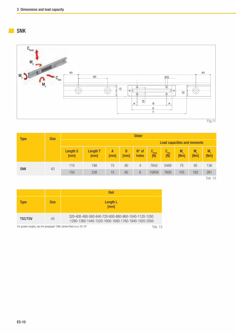
ES-10
SNK
Fig.11
Type SizeSlider
Load capacities and moments
Length S
[mm]
Length T
[mm]
A
[mm]
B
[mm]
N° of
holes
C0rad
[N]
C0ax
[N]
Mx
[Nm]
My
[Nm]
Mz
[Nm]
SNK 43110 198 15 80 4 7842 5489 75 95 136
150 238 15 60 6 10858 7600 105 182 261
Tab. 12
Rail
Type Size Length L
[mm]
TSC/TSV 43320-400-480-560-640-720-800-880-960-1040-1120-1200
-1280-1360-1440-1520-1600-1680-1760-1840-1920-2000
Tab. 13
C0rad
C0ax
Mz
My
Mx
4080
40M5
A AB
ST
19
3 Dimensions and load capacity
For greater lengths, see the paragraph “SNK Jointed Rails on p. ES-18”
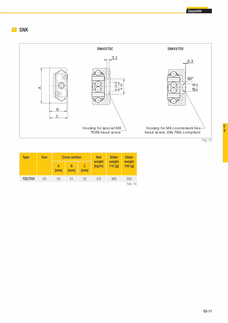
ES-11
Easyslide
ES
SNK
Fig. 12
Type Size Cross-section Rail
weight
[kg/m]
Slider
weight
110 [g]
Slider
weight
150 [g]A
[mm]
B
[mm]
C
[mm]
TSC/TSV 43 43 21 22 2,6 360 550
Tab. 14
SNK43/TSC SNK43/TSV
3,1
Ø 1
0,5
Ø 1
8
housing for special M8TORX head screw
Ø 9
90°
0,3
housing for M8 countersunk hexhead screw, DIN 7991 compliant
B
C
A

ES-12
4 Technical instructions
Static load
The maximum static loads of the Easyslide series are based on the slider
length and are listed in the tables of the previous pages. These load ca-
pacities are valid for a loading point of forces and moments in the center
of the slider (for off-center loading, see ES-13). The load capacities are
independent of the position of the slider inside the rails. During the sta-
tic tests the radial load capacity, C0rad
, the axial load capacity, C0ax
, and
moments Mx, M
y and M
z indicate the maximum permissible values of the
loads. Higher loads negatively affect the running properties and the total
mechanical strength may be compromised. A safety factor, S0, is used to
verify the static load, which takes into account the basic parameters of the
application and is defi ned in more detail in the following table:
Safety factor S0
Tab. 15
Neither shocks nor vibrations, smooth and low-frequency reverse,
high assembly accuracy, no elastic deformations1 - 1.5
Normal installation conditions 1.5 - 2
Shocks and vibrations, high-frequency reverse, signifi cant elastic deformation 2 - 3.5
The ratio of the actual load to maximum permissible load may be as large
as the reciprocal of the accepted safety factor, S0, at the most.
Fig. 13
Fig. 14
The formulas above apply for a single load case. If there are two or more of
the described forces simultaneously, the following check must be made:
P0rad
1
C0rad
S0
≤P
0ax 1
C0ax
S0
≤M
1 1
Mx S
0
≤M
2 1
My S
0
≤M
3 1
Mz S
0
≤
P0rad
P0ax
M1 M
2 M
3
C0rad
C0ax
Mx M
y M
z
+ + + + ≤1
S0
P0rad
= effective radial load
C0rad
= permissible radial load
P0ax
= effective axial load
C0ax
= permissible axial load
M1 = effective moment in the x-direction
Mx = permissible moment in the x-direction
M2 = effective moment in the y-direction
My = permissible moment in the y-direction
M3 = effective moment in the z-direction
Mz = permissible moment in the z-direction
Technical instructions
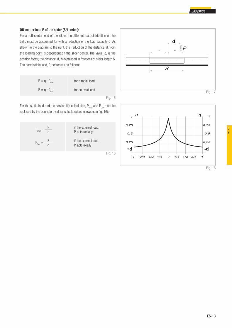
ES-13
Easyslide
ES
Off-center load P of the slider (SN series):
For an off-center load of the slider, the different load distribution on the
balls must be accounted for with a reduction of the load capacity C. As
shown in the diagram to the right, this reduction of the distance, d, from
the loading point is dependent on the slider center. The value, q, is the
position factor, the distance, d, is expressed in fractions of slider length S.
The permissible load, P, decreases as follows:
Fig. 15
Fig. 16
For the static load and the service life calculation, P0rad
and P0ax
must be
replaced by the equivalent values calculated as follows (see fi g. 16):
Fig. 17
Fig. 18
P = q · C0rad
P = q · C0ax
for a radial load
for an axial load
if the external load,
P, acts radially
if the external load,
P, acts axially
P
qP
0rad =
P
qP
0ax =
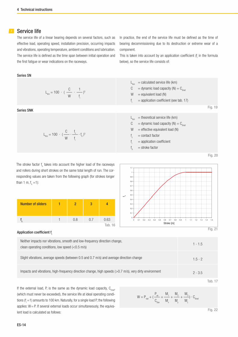
ES-14
4 Technical instructions
Service lifeThe service life of a linear bearing depends on several factors, such as
effective load, operating speed, installation precision, occurring impacts
and vibrations, operating temperature, ambient conditions and lubrication.
The service life is defi ned as the time span between initial operation and
the fi rst fatigue or wear indications on the raceways.
In practice, the end of the service life must be defi ned as the time of
bearing decommissioning due to its destruction or extreme wear of a
component.
This is taken into account by an application coeffi cient (fi in the formula
below), so the service life consists of:
Fig. 19
Lkm
= 100 · ( ––– · ––– )3C
W
1
fi
Lkm
= calculated service life ( km )
C = dynamic load capacity ( N ) = C0rad
W = equivalent load ( N )
fi = application coeffi cient (see tab. 17)
Tab. 17
Neither impacts nor vibrations, smooth and low-frequency direction change,
clean operating conditions, low speed ( <0.5 m/s)1 - 1.5
Slight vibrations, average speeds (between 0.5 and 0.7 m/s) and average direction change 1.5 - 2
Impacts and vibrations, high-frequency direction change, high speeds ( >0.7 m/s), very dirty environment 2 - 3.5
If the external load, P, is the same as the dynamic load capacity, C0rad
,
(which must never be exceeded ), the service life at ideal operating condi-
tions ( fi = 1) amounts to 100 km. Naturally, for a single load P, the following
applies: W = P. If several external loads occur simultaneously, the equiva-
lent load is calculated as follows:
W = Prad
+ ( ––– + ––– + ––– + –––) · C0rad
Pax
C0ax
M1
Mx
M2
My
M3
Mz
Application coeffi cient fi
Fig. 22
Series SN
Series SNK
Fig. 20
LKm
= 100 · ( ––– · ––– · fh )3
fc
fi
Lkm
= theoretical service life ( km )
C = dynamic load capacity ( N ) = C0rad
W = effective equivalent load ( N )
fc = contact factor
fi = application coeffi cient
fh = stroke factor
Number of sliders 1 2 3 4
fc
1 0.8 0.7 0.63
Tab. 16
The stroke factor fh takes into account the higher load of the raceways
and rollers during short strokes on the same total length of run. The cor-
responding values are taken from the following graph (for strokes longer
than 1 m, fh =1):
Fig. 21
Stroke [m]
f h
C
W

ES-15
Easyslide
ES
Clearance and preloadThe linear ball bearings of the SN and SNK series are mounted as standard
with no play. For more information, please contact Rollon technical support.
* for higher preload, contact Rollon technical support.
Preload classes
Increased clearance No clearance Increased preload
G1
Standard K1
Tab. 18
Coeffi cient of frictionWith correct lubrication and installation on level and rigid surfaces and suf-
fi cient parallelism for rail pairs, the friction value is less than or equal to 0.01.
This value can vary depending on the installation situation (see pg. ES-19,
Instructions for use). For the SNK series, the coeffi cient of friction is equal
to or less than 0.06.
Linear accuracyWith installation of the rails using all bolts on a perfectly plane support
surface with the fi xing holes in a straight line, the linear accuracy of the
sliders to an external reference results from the following equation:
Fig. 23
SpeedThe linear bearings of the SN series can be used up to an operating speed
of 0.8 m/s (31.5 in/s). With high-frequency direction changes and the
resulting high accelerations, as well as with long ball cages, there is a risk
of cage creep (see pg. ES-19, Instructions for use). The SNK series rails,
on the other hand, reach a maximum speed of 1.5 m/s, and there is no
risk of cage creep.
// = –––– (mm)√H
300H = Stroke
TemperatureThe SN series can be used in ambient temperatures from -20 °C to +170 °C
(-4 °F to +338 °F ). The SNK series can be used at ambient temperatures
between -20 °C and + 70 °C. A lithium lubricant for high operating tem-
peratures is recommended for temperatures above +130 °C (+266 °F ).

ES-16
4 Technical instructions
Anticorrosive protection■ The SN series standard anticorrosive protection is electrolytic zinc pla-
ting in accordance with ISO 2081. If increased anticorrosive protection
is required, chemically nickel plated rails and stainless steel ball bea-
rings are available.
Lubrication SNRecommended lubrication intervals are heavily dependent upon the am-
bient conditions. Under normal conditions, lubrication is recommended
after 100 km operational performance or after an operating period of 6
months. In critical application cases the interval should be shorter. Please
clean the raceways carefully before lubrication. Raceways and spaces of
the ball cage are lubricated with a lithium lubricant of average consistency
(roller bearing lubricant).
Different lubricants are available on request for special applications:
■ FDA-approved lubricant for use in the food industry
■ specifi c lubricant for clean rooms
■ Numerous application-specifi c surface treatments are available upon
request, e.g., FDA-approved nickel plating for use in the food industry.
For more information, please contact Rollon technical support.
■ specifi c lubricant for the marine technology sector
■ specifi c lubricant for high and low temperatures
For specifi c information, contact Rollon technical support.
Under normal conditions, correct lubrication:
■ reduces friction
■ reduces wear
■ reduces stress on contact surfaces due to elastic deformation
■ reduces noise during operation
■ increases the regularity of the rolling movement
Fig. 24Grease applicator M6x1 DIN 3405 compliant
Tab. 19
Lubricant Thickening agent Temperature range
[°C]
Dynamic viscosity
[mPas]
Mineral oil Lithium soap -30... to +120 < 1000
Roller bearing lubricant Lithium soap-30 to +170
4500
Lubrication SNK
Lubrication when using N-sliders SNK43
The SNK43 sliders are fi tted with a self lubricating kit provided to periodi-
cally lubricate the slider.
This provides a progressive release of lubricant (see tab. 36) on the race-
way during operation of the slider. The expected service life is up to
2 million cycles, depending on the type of application. The zerk fi ttings
(see fi g. 24) provide the lubrication.
Different lubricants are available on request for special applications:
■ FDA-approved lubricant for use in the food industry
■ specifi c lubricant for clean rooms
■ specifi c lubricant for the marine technology sector
■ specifi c lubricant for high and low temperatures
For specifi c information, contact Rollon technical support.
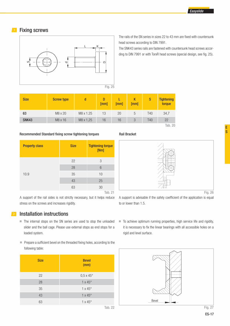
ES-17
Easyslide
ES
Fixing screws
Recommended Standard fi xing screw tightening torques
Property class Size Tightening torque
[Nm]
10.9
22 3
28 6
35 10
43 25
63 30
Tab. 20
S d
L K
DSize Screw type d D
[mm]
L
[mm]
K
[mm]
S Tightening
torque
63 M8 x 20 M8 x 1.25 13 20 5 T40 34,7
SNK43 M8 x 16 M8 x 1,25 16 16 3 T40 22
Fig. 25
Tab. 21
The rails of the SN series in sizes 22 to 43 mm are fi xed with countersunk
head screws according to DIN 7991.
The SNK43 series rails are fastened with countersunk head screws accor-
ding to DIN 7991 or with TorxR head screws (special design, see fi g. 25).
Installation instructions
■ The internal stops on the SN series are used to stop the unloaded
slider and the ball cage. Please use external stops as end stops for a
loaded system.
■ To achieve optimum running properties, high service life and rigidity,
it is necessary to fi x the linear bearings with all accessible holes on a
rigid and level surface.
Tab. 22
■ Prepare a suffi cient bevel on the threaded fi xing holes, according to the
following table:
Bevel
Size Bevel
(mm)
22 0,5 x 45°
28 1 x 45°
35 1 x 45°
43 1 x 45°
63 1 x 45°
Fig. 27
A support of the rail sides is not strictly necessary, but it helps reduce
stress on the screws and increases rigidity.
A support is advisable if the safety coeffi cient of the application is equal
to or lower than 1.5.
Rail Bracket
Fig. 26
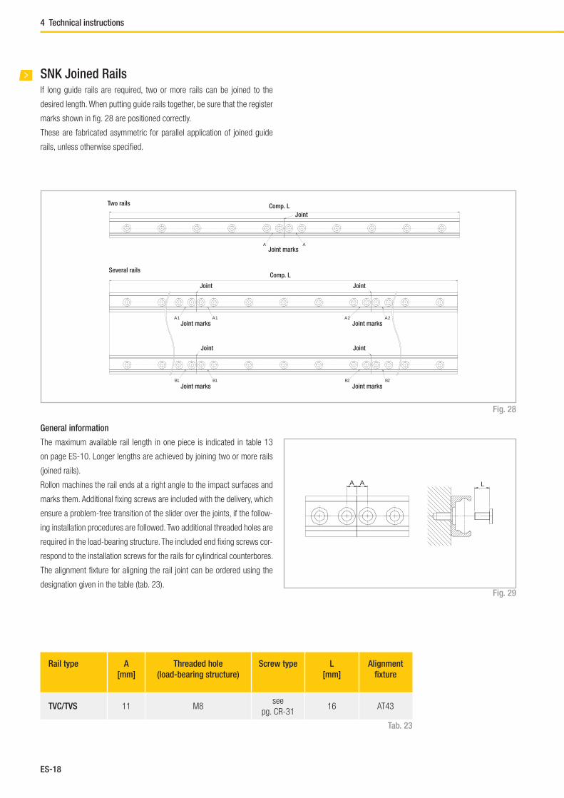
ES-18
A A
A1 A1 A2 A2
B2B2B1 B1
If long guide rails are required, two or more rails can be joined to the
desired length. When putting guide rails together, be sure that the register
marks shown in fi g. 28 are positioned correctly.
These are fabricated asymmetric for parallel application of joined guide
rails, unless otherwise specifi ed.
Fig. 28
Two rails
Several rails
Comp. L
Comp. L
Joint
Joint marks
Joint marks
Joint marks
Joint marks
Joint marks
Joint
Joint
Joint
Joint
SNK Joined Rails
General information
The maximum available rail length in one piece is indicated in table 13
on page ES-10. Longer lengths are achieved by joining two or more rails
(joined rails).
Rollon machines the rail ends at a right angle to the impact surfaces and
marks them. Additional fi xing screws are included with the delivery, which
ensure a problem-free transition of the slider over the joints, if the follow-
ing installation procedures are followed. Two additional threaded holes are
required in the load-bearing structure. The included end fi xing screws cor-
respond to the installation screws for the rails for cylindrical counterbores.
The alignment fi xture for aligning the rail joint can be ordered using the
designation given in the table (tab. 23).Fig. 29
Rail type A
[mm]
Threaded hole
(load-bearing structure)
Screw type L
[mm]
Alignment
fi xture
TVC/TVS 11 M8see
pg. CR-3116 AT43
Tab. 23
LA A
4 Technical instructions

ES-19
Easyslide
ES
SN instructions for use SNK instructions for use■ For linear bearings of the SN series, the sliders are guided through a
ball cage inside the rails. When the sliders run their course relative to
the rails, the ball cage moves along for half the slider stroke. The stroke
ends as soon as the slider reaches the end of the cage.
Normally the cage moves synchronously to the balls at half the speed
of the slider. Any occurring cage slip affects the synchronous move-
ment of the ball cage negatively, causing it to reach the internal stops
prematurely (cage creep). This reduces the stroke. However, the stroke
value can be normalized at any time by moving the slider to the stop
in the stopped cage. This moving of the slider relative to the cage will
have increased resistance, which is dependent on the working load.
■ The causes of cage creep can be installation accuracy, dynamics, and
load changes. The effects can be minimized by observing the following
advice:
- The stroke should always remain constant and come as close as
possible to the nominal stroke of the linear bearing.
- For applications with various strokes, make sure that the drive is
suffi ciently dimensioned to guarantee a movement of the slider relative
to the cage. A coeffi cient of friction of 0.1 should be calculated for
this.
- Another possibility is to include a maximum stroke without load in the
working cycle in order to resynchronize the slider and ball cage.
Parallelism errors or inaccuracies in the installation or in the mounting
surfaces of mounted pairs can infl uence the cage creep.
■ Series SN linear bearings should only be used for horizontal move-
ment.
■ SNK: Always handle the slider out of the rail by its plastic retainer to
prevent ball bearings from escaping.
If the bearing cage covers one or more fi xing holes for the rail, access
holes are made in the cage. The number and position of the holes can
vary in different supplies.
Access to all fi xing screws of the rail is guaranteed in all cases by positio-
ning the cage aligned with the holes.
Fig. 30
Access holes
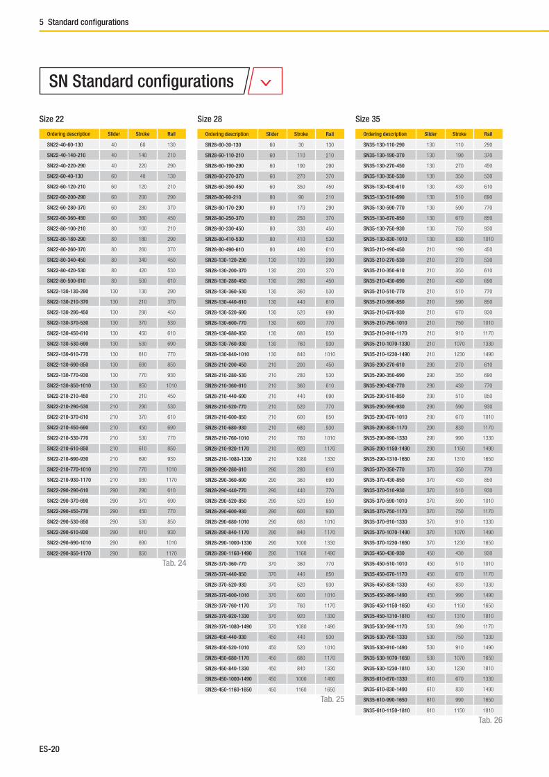
ES-20
5 Standard confi gurations
Ordering description Slider Stroke Rail
SN22-40-60-130 40 60 130
SN22-40-140-210 40 140 210
SN22-40-220-290 40 220 290
SN22-60-40-130 60 40 130
SN22-60-120-210 60 120 210
SN22-60-200-290 60 200 290
SN22-60-280-370 60 280 370
SN22-60-360-450 60 360 450
SN22-80-100-210 80 100 210
SN22-80-180-290 80 180 290
SN22-80-260-370 80 260 370
SN22-80-340-450 80 340 450
SN22-80-420-530 80 420 530
SN22-80-500-610 80 500 610
SN22-130-130-290 130 130 290
SN22-130-210-370 130 210 370
SN22-130-290-450 130 290 450
SN22-130-370-530 130 370 530
SN22-130-450-610 130 450 610
SN22-130-530-690 130 530 690
SN22-130-610-770 130 610 770
SN22-130-690-850 130 690 850
SN22-130-770-930 130 770 930
SN22-130-850-1010 130 850 1010
SN22-210-210-450 210 210 450
SN22-210-290-530 210 290 530
SN22-210-370-610 210 370 610
SN22-210-450-690 210 450 690
SN22-210-530-770 210 530 770
SN22-210-610-850 210 610 850
SN22-210-690-930 210 690 930
SN22-210-770-1010 210 770 1010
SN22-210-930-1170 210 930 1170
SN22-290-290-610 290 290 610
SN22-290-370-690 290 370 690
SN22-290-450-770 290 450 770
SN22-290-530-850 290 530 850
SN22-290-610-930 290 610 930
SN22-290-690-1010 290 690 1010
SN22-290-850-1170 290 850 1170
Size 22
Ordering description Slider Stroke Rail
SN28-60-30-130 60 30 130
SN28-60-110-210 60 110 210
SN28-60-190-290 60 190 290
SN28-60-270-370 60 270 370
SN28-60-350-450 60 350 450
SN28-80-90-210 80 90 210
SN28-80-170-290 80 170 290
SN28-80-250-370 80 250 370
SN28-80-330-450 80 330 450
SN28-80-410-530 80 410 530
SN28-80-490-610 80 490 610
SN28-130-120-290 130 120 290
SN28-130-200-370 130 200 370
SN28-130-280-450 130 280 450
SN28-130-360-530 130 360 530
SN28-130-440-610 130 440 610
SN28-130-520-690 130 520 690
SN28-130-600-770 130 600 770
SN28-130-680-850 130 680 850
SN28-130-760-930 130 760 930
SN28-130-840-1010 130 840 1010
SN28-210-200-450 210 200 450
SN28-210-280-530 210 280 530
SN28-210-360-610 210 360 610
SN28-210-440-690 210 440 690
SN28-210-520-770 210 520 770
SN28-210-600-850 210 600 850
SN28-210-680-930 210 680 930
SN28-210-760-1010 210 760 1010
SN28-210-920-1170 210 920 1170
SN28-210-1080-1330 210 1080 1330
SN28-290-280-610 290 280 610
SN28-290-360-690 290 360 690
SN28-290-440-770 290 440 770
SN28-290-520-850 290 520 850
SN28-290-600-930 290 600 930
SN28-290-680-1010 290 680 1010
SN28-290-840-1170 290 840 1170
SN28-290-1000-1330 290 1000 1330
SN28-290-1160-1490 290 1160 1490
SN28-370-360-770 370 360 770
SN28-370-440-850 370 440 850
SN28-370-520-930 370 520 930
SN28-370-600-1010 370 600 1010
SN28-370-760-1170 370 760 1170
SN28-370-920-1330 370 920 1330
SN28-370-1080-1490 370 1080 1490
SN28-450-440-930 450 440 930
SN28-450-520-1010 450 520 1010
SN28-450-680-1170 450 680 1170
SN28-450-840-1330 450 840 1330
SN28-450-1000-1490 450 1000 1490
SN28-450-1160-1650 450 1160 1650
Size 28
Ordering description Slider Stroke Rail
SN35-130-110-290 130 110 290
SN35-130-190-370 130 190 370
SN35-130-270-450 130 270 450
SN35-130-350-530 130 350 530
SN35-130-430-610 130 430 610
SN35-130-510-690 130 510 690
SN35-130-590-770 130 590 770
SN35-130-670-850 130 670 850
SN35-130-750-930 130 750 930
SN35-130-830-1010 130 830 1010
SN35-210-190-450 210 190 450
SN35-210-270-530 210 270 530
SN35-210-350-610 210 350 610
SN35-210-430-690 210 430 690
SN35-210-510-770 210 510 770
SN35-210-590-850 210 590 850
SN35-210-670-930 210 670 930
SN35-210-750-1010 210 750 1010
SN35-210-910-1170 210 910 1170
SN35-210-1070-1330 210 1070 1330
SN35-210-1230-1490 210 1230 1490
SN35-290-270-610 290 270 610
SN35-290-350-690 290 350 690
SN35-290-430-770 290 430 770
SN35-290-510-850 290 510 850
SN35-290-590-930 290 590 930
SN35-290-670-1010 290 670 1010
SN35-290-830-1170 290 830 1170
SN35-290-990-1330 290 990 1330
SN35-290-1150-1490 290 1150 1490
SN35-290-1310-1650 290 1310 1650
SN35-370-350-770 370 350 770
SN35-370-430-850 370 430 850
SN35-370-510-930 370 510 930
SN35-370-590-1010 370 590 1010
SN35-370-750-1170 370 750 1170
SN35-370-910-1330 370 910 1330
SN35-370-1070-1490 370 1070 1490
SN35-370-1230-1650 370 1230 1650
SN35-450-430-930 450 430 930
SN35-450-510-1010 450 510 1010
SN35-450-670-1170 450 670 1170
SN35-450-830-1330 450 830 1330
SN35-450-990-1490 450 990 1490
SN35-450-1150-1650 450 1150 1650
SN35-450-1310-1810 450 1310 1810
SN35-530-590-1170 530 590 1170
SN35-530-750-1330 530 750 1330
SN35-530-910-1490 530 910 1490
SN35-530-1070-1650 530 1070 1650
SN35-530-1230-1810 530 1230 1810
SN35-610-670-1330 610 670 1330
SN35-610-830-1490 610 830 1490
SN35-610-990-1650 610 990 1650
SN35-610-1150-1810 610 1150 1810
Size 35
Tab. 24
Tab. 25
Tab. 26
SN Standard confi gurations
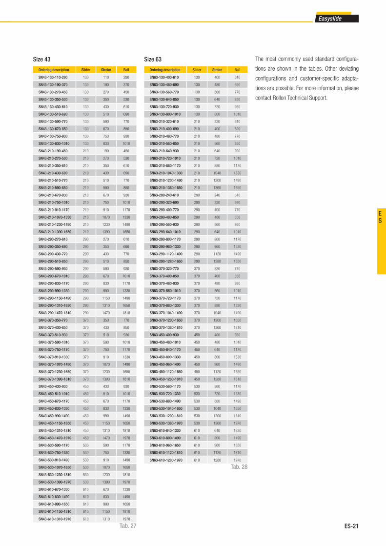
ES-21
Easyslide
ES
Ordering description Slider Stroke Rail
SN43-130-110-290 130 110 290
SN43-130-190-370 130 190 370
SN43-130-270-450 130 270 450
SN43-130-350-530 130 350 530
SN43-130-430-610 130 430 610
SN43-130-510-690 130 510 690
SN43-130-590-770 130 590 770
SN43-130-670-850 130 670 850
SN43-130-750-930 130 750 930
SN43-130-830-1010 130 830 1010
SN43-210-190-450 210 190 450
SN43-210-270-530 210 270 530
SN43-210-350-610 210 350 610
SN43-210-430-690 210 430 690
SN43-210-510-770 210 510 770
SN43-210-590-850 210 590 850
SN43-210-670-930 210 670 930
SN43-210-750-1010 210 750 1010
SN43-210-910-1170 210 910 1170
SN43-210-1070-1330 210 1070 1330
SN43-210-1230-1490 210 1230 1490
SN43-210-1390-1650 210 1390 1650
SN43-290-270-610 290 270 610
SN43-290-350-690 290 350 690
SN43-290-430-770 290 430 770
SN43-290-510-850 290 510 850
SN43-290-590-930 290 590 930
SN43-290-670-1010 290 670 1010
SN43-290-830-1170 290 830 1170
SN43-290-990-1330 290 990 1330
SN43-290-1150-1490 290 1150 1490
SN43-290-1310-1650 290 1310 1650
SN43-290-1470-1810 290 1470 1810
SN43-370-350-770 370 350 770
SN43-370-430-850 370 430 850
SN43-370-510-930 370 510 930
SN43-370-590-1010 370 590 1010
SN43-370-750-1170 370 750 1170
SN43-370-910-1330 370 910 1330
SN43-370-1070-1490 370 1070 1490
SN43-370-1230-1650 370 1230 1650
SN43-370-1390-1810 370 1390 1810
SN43-450-430-930 450 430 930
SN43-450-510-1010 450 510 1010
SN43-450-670-1170 450 670 1170
SN43-450-830-1330 450 830 1330
SN43-450-990-1490 450 990 1490
SN43-450-1150-1650 450 1150 1650
SN43-450-1310-1810 450 1310 1810
SN43-450-1470-1970 450 1470 1970
SN43-530-590-1170 530 590 1170
SN43-530-750-1330 530 750 1330
SN43-530-910-1490 530 910 1490
SN43-530-1070-1650 530 1070 1650
SN43-530-1230-1810 530 1230 1810
SN43-530-1390-1970 530 1390 1970
SN43-610-670-1330 610 670 1330
SN43-610-830-1490 610 830 1490
SN43-610-990-1650 610 990 1650
SN43-610-1150-1810 610 1150 1810
SN43-610-1310-1970 610 1310 1970
Size 43
Ordering description Slider Stroke Rail
SN63-130-400-610 130 400 610
SN63-130-480-690 130 480 690
SN63-130-560-770 130 560 770
SN63-130-640-850 130 640 850
SN63-130-720-930 130 720 930
SN63-130-800-1010 130 800 1010
SN63-210-320-610 210 320 610
SN63-210-400-690 210 400 690
SN63-210-480-770 210 480 770
SN63-210-560-850 210 560 850
SN63-210-640-930 210 640 930
SN63-210-720-1010 210 720 1010
SN63-210-880-1170 210 880 1170
SN63-210-1040-1330 210 1040 1330
SN63-210-1200-1490 210 1200 1490
SN63-210-1360-1650 210 1360 1650
SN63-290-240-610 290 240 610
SN63-290-320-690 290 320 690
SN63-290-400-770 290 400 770
SN63-290-480-850 290 480 850
SN63-290-560-930 290 560 930
SN63-290-640-1010 290 640 1010
SN63-290-800-1170 290 800 1170
SN63-290-960-1330 290 960 1330
SN63-290-1120-1490 290 1120 1490
SN63-290-1280-1650 290 1280 1650
SN63-370-320-770 370 320 770
SN63-370-400-850 370 400 850
SN63-370-480-930 370 480 930
SN63-370-560-1010 370 560 1010
SN63-370-720-1170 370 720 1170
SN63-370-880-1330 370 880 1330
SN63-370-1040-1490 370 1040 1490
SN63-370-1200-1650 370 1200 1650
SN63-370-1360-1810 370 1360 1810
SN63-450-400-930 450 400 930
SN63-450-480-1010 450 480 1010
SN63-450-640-1170 450 640 1170
SN63-450-800-1330 450 800 1330
SN63-450-960-1490 450 960 1490
SN63-450-1120-1650 450 1120 1650
SN63-450-1280-1810 450 1280 1810
SN63-530-560-1170 530 560 1170
SN63-530-720-1330 530 720 1330
SN63-530-880-1490 530 880 1490
SN63-530-1040-1650 530 1040 1650
SN63-530-1200-1810 530 1200 1810
SN63-530-1360-1970 530 1360 1970
SN63-610-640-1330 610 640 1330
SN63-610-800-1490 610 800 1490
SN63-610-960-1650 610 960 1650
SN63-610-1120-1810 610 1120 1810
SN63-610-1280-1970 610 1280 1970
Size 63
Tab. 27
Tab. 28
The most commonly used standard confi gura-
tions are shown in the tables. Other deviating
confi gurations and customer-specifi c adapta-
tions are possible. For more information, please
contact Rollon Technical Support.
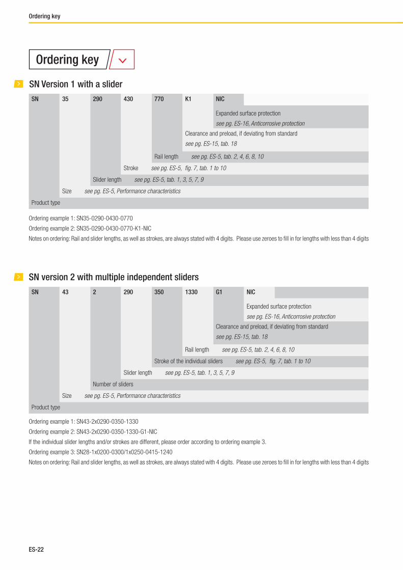
ES-22
Ordering key
SN 35 290 430 770 K1 NIC
Expanded surface protection
see pg. ES-16, Anticorrosive protection
Clearance and preload, if deviating from standard
see pg. ES-15, tab. 18
Rail length see pg. ES-5, tab. 2, 4, 6, 8, 10
Stroke see pg. ES-5, fi g. 7, tab. 1 to 10
Slider length see pg. ES-5, tab. 1, 3, 5, 7, 9
Size see pg. ES-5, Performance characteristics
Product type
SN Version 1 with a slider
Ordering example 1: SN35-0290-0430-0770
Ordering example 2: SN35-0290-0430-0770-K1-NIC
Notes on ordering: Rail and slider lengths, as well as strokes, are always stated with 4 digits. Please use zeroes to fi ll in for lengths with less than 4 digits
SN version 2 with multiple independent sliders
SN 43 2 290 350 1330 G1 NIC
Expanded surface protection
see pg. ES-16, Anticorrosive protection
Clearance and preload, if deviating from standard
see pg. ES-15, tab. 18
Rail length see pg. ES-5, tab. 2, 4, 6, 8, 10
Stroke of the individual sliders see pg. ES-5, fi g. 7, tab. 1 to 10
Slider length see pg. ES-5, tab. 1, 3, 5, 7, 9
Number of sliders
Size see pg. ES-5, Performance characteristics
Product type
Ordering example 1: SN43-2x0290-0350-1330
Ordering example 2: SN43-2x0290-0350-1330-G1-NIC
If the individual slider lengths and/or strokes are different, please order according to ordering example 3.
Ordering example 3: SN28-1x0200-0300/1x0250-0415-1240
Notes on ordering: Rail and slider lengths, as well as strokes, are always stated with 4 digits. Please use zeroes to fi ll in for lengths with less than 4 digits
Ordering key

ES-23
Easyslide
ES
SN Version 3 with multiple synchronized sliders
SN 63 850 (370+290) 400 1330 K1 NIC
Expanded surface protection
see pg. ES-16, Anticorrosive protection
Clearance and preload, if deviating from standard
see pg. ES-15, tab. 18
Rail length see pg. ES-5, tab. 2, 4, 6, 8, 10
Stroke see pg. ES-5, fi g. 7, tab. 1 to 10
Individual length of slider see pg. ES-5, tab. 1, 3, 5, 7, 9
Apparent length, S´ of the slider see pg. ES-8, fi g. 9
Size see pg. ES-5 Performance characteristics
Product type
Ordering example 1: SN63-0850(370+290)-0400-1330
Ordering example 2: SN63-0850(370+290)-0400-1330-K1-NI C
Notes on ordering: Rail and slider lengths, as well as strokes, are always stated with 4 digits. Please use zeroes to fi ll in for lengths with less than 4 digits
Serie SNK
SNK 43 1 110 2320 TSC NIC
For surface protection different from standard ISO 2081
see pg. ES-16
Tipo di guida see pg. ES-10 e ES-11
Rail length see pg. ES-10 tab 13
Slider length see pg. ES-10.
Number of sliders for each rail
Size see pg. ES-5 Performance characteristics
Product type
Ordering example: SNK43-1x110-02320-TSC-NIC
Rail kit: 1x2000+1x320 (only for joined rails)
Drilling pattern: 40-40x80-40//40-15x80-40 (always state the drilling pattern separately)
Note for ordering: Rail lengths are always shown with fi ve fi gures, and slider lengths are indicated with three fi gures preceded by zeros

ES-24
Notes
Notes
Mono Rail
FrontespizioMonorail.indd 1 19/03/2014 15:43:06

MR-2
Mono Rails are profi le rails for the highest degree of precision
The running grooves are ground in semicircular profi le and have a contact
angle of 45° in X-arrangement so that the same load capacity is guaran-
teed in all principle directions. Use of large steel balls enables high load
and moment capacities. All carriages in size 55 are equipped with ball
chains.
The most important characteristics:
■ X-arrangement with 2-point contact of the raceways
■ Uniform loading capacity in all main directions
■ High ability for self-regulating
■ Small differential slip in comparison to 4-point contact
■ Very quiet running and low operating noise
■ Low maintenance due to advanced lubrication chamber
■ Small displacement force in preload compared to 4-point contact
■ Mono Rail profi le rails meet the market standard and can replace
linear rails of the same design from other manufacturers while
maintaining the main dimensions
■ Miniature Mono Rails available in a standard or large version
■ Miniature Mono Rail available in Martensite stainless steel.
Preferred areas of application:
■ Construction and machine technology ( safety doors, feeding )
■ Packaging machines
■ Special purpose machinery
■ Logistics ( e.g., handling units )
■ Medical technology ( e.g., X-ray equipment, hospital gurneys )
■ Semiconductors and electronics industry
Fig. 1
1 Product explanation
Product explanation

MR-3
Mono Rail
MRS
Standard carriage with fl ange.
MRS...L
Carriage in long version for holding larger loads. MRS...L is the version
with fl ange.
MRS...LW
Carriage in long version without fl ange.
MRS...W / MRT...W
Carriage without fl ange, also called block. Available in two different
heights. MRT is the lower version.
Fig. 2
Fig.3
Fig. 4
Fig. 5

MR-4
MRR...F
Guide rail MRR...F for bolting from below with threaded holes. Design with
smooth surface without bevels.
MRT...SW
Carriage without fl ange in short version for lower loads with equally high
precision.
Fig. 6
Fig. 7
Fig. 8
Fig. 9
Standard width
Compact technology and high performance in its smallest structural
shape.
Large width
Wide miniature profi le rails, with a compact size, allow the acceptance of
higher forces and moments. Especially suited for single rail applications.
1 Product explanation
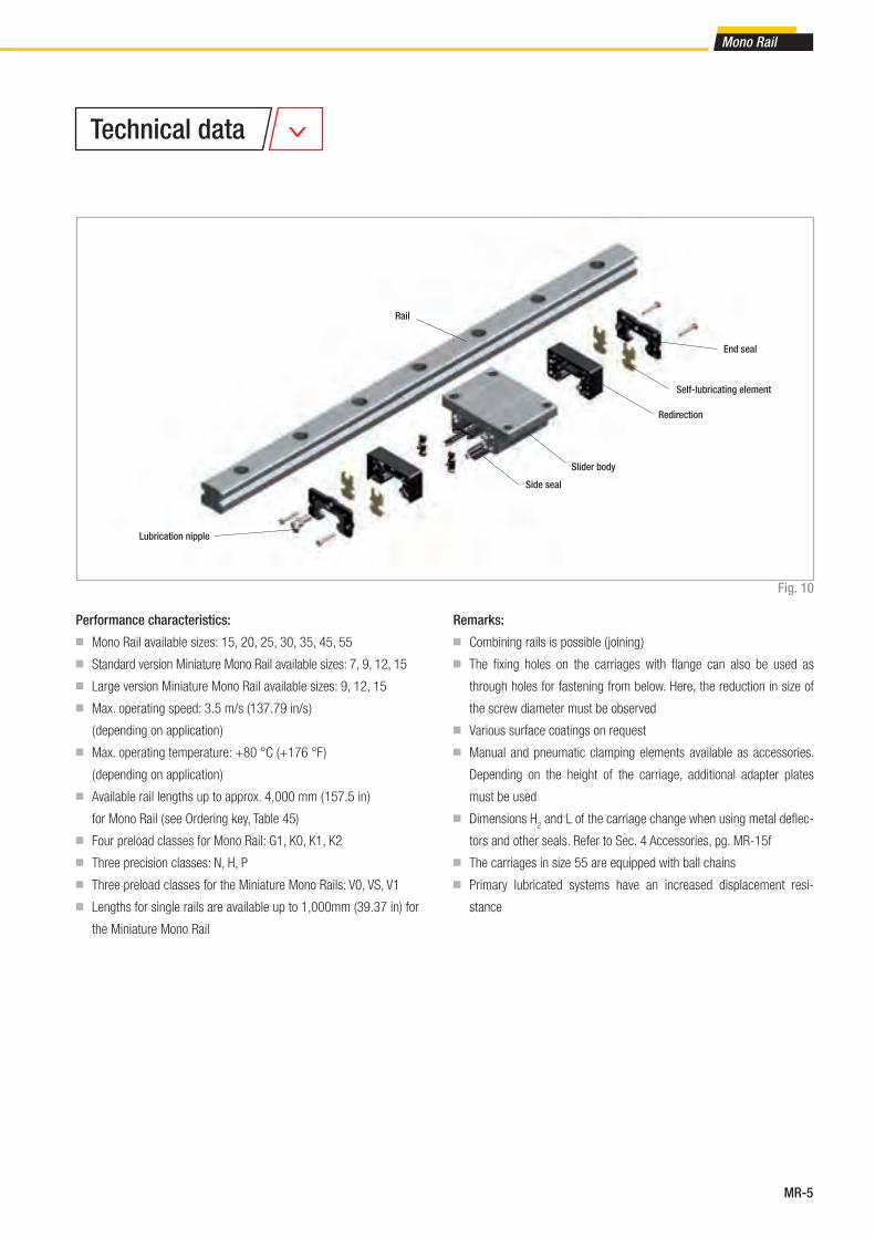
MR-5
Mono Rail
Rail
Lubrication nipple
Performance characteristics:
■ Mono Rail available sizes: 15, 20, 25, 30, 35, 45, 55
■ Standard version Miniature Mono Rail available sizes: 7, 9, 12, 15
■ Large version Miniature Mono Rail available sizes: 9, 12, 15
■ Max. operating speed: 3.5 m/s (137.79 in/s )
( depending on application )
■ Max. operating temperature: +80 °C (+176 °F )
( depending on application )
■ Available rail lengths up to approx. 4,000 mm ( 157.5 in )
for Mono Rail ( see Ordering key, Table 45)
■ Four preload classes for Mono Rail: G1, K0, K1, K2
■ Three precision classes: N, H, P
■ Three preload classes for the Miniature Mono Rails: V0, VS, V1
■ Lengths for single rails are available up to 1,000mm (39.37 in) for
the Miniature Mono Rail
Remarks:
■ Combining rails is possible ( joining )
■ The fi xing holes on the carriages with fl ange can also be used as
through holes for fastening from below. Here, the reduction in size of
the screw diameter must be observed
■ Various surface coatings on request
■ Manual and pneumatic clamping elements available as accessories.
Depending on the height of the carriage, additional adapter plates
must be used
■ Dimensions H2 and L of the carriage change when using metal defl ec-
tors and other seals. Refer to Sec. 4 Accessories, pg. MR-15f
■ The carriages in size 55 are equipped with ball chains
■ Primary lubricated systems have an increased displacement resi-
stance
Side seal
Slider body
Redirection
Self-lubricating element
Fig. 10
End seal
Technical data
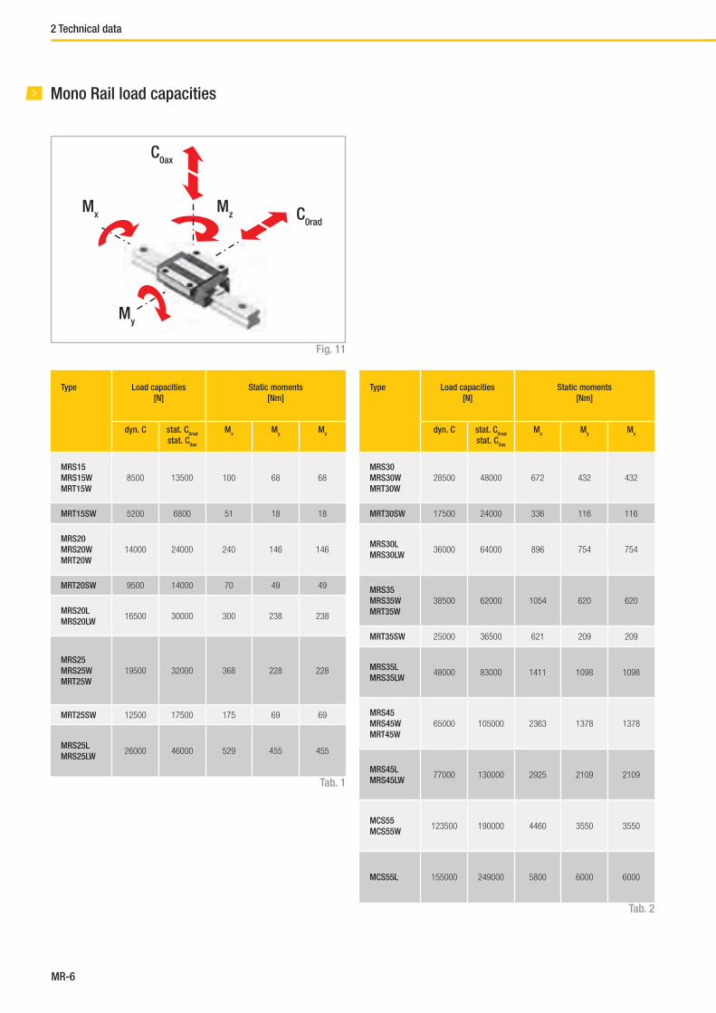
MR-6
2 Technical data
Mono Rail load capacities
C0ax
C0rad
Fig. 11
Type Load capacities
[N]
Static moments
[Nm]
dyn. C stat. C0rad
stat. C0ax
Mx
My
Mz
MRS30
MRS30W
MRT30W
28500 48000 672 432 432
MRT30SW 17500 24000 336 116 116
MRS30L
MRS30LW36000 64000 896 754 754
MRS35
MRS35W
MRT35W
38500 62000 1054 620 620
MRT35SW 25000 36500 621 209 209
MRS35L
MRS35LW48000 83000 1411 1098 1098
MRS45
MRS45W
MRT45W
65000 105000 2363 1378 1378
MRS45L
MRS45LW77000 130000 2925 2109 2109
MCS55
MCS55W123500 190000 4460 3550 3550
MCS55L 155000 249000 5800 6000 6000
Type Load capacities
[N]
Static moments
[Nm]
dyn. C stat. C0rad
stat. C0ax
Mx
My
Mz
MRS15
MRS15W
MRT15W
8500 13500 100 68 68
MRT15SW 5200 6800 51 18 18
MRS20
MRS20W
MRT20W
14000 24000 240 146 146
MRT20SW 9500 14000 70 49 49
MRS20L
MRS20LW16500 30000 300 238 238
MRS25
MRS25W
MRT25W
19500 32000 368 228 228
MRT25SW 12500 17500 175 69 69
MRS25L
MRS25LW26000 46000 529 455 455
Tab. 2
Mx
Mz
My
Tab. 1

MR-7
Mono Rail
Type Load capacities
[N]
Static moments
[Nm]
dyn. C100
stat. C0
Mx
My
Mz
MR07MN 890 1400 5.2 3.3 3.3
MR09MN 1570 2495 11.7 6.4 6.4
MR12MN 2308 3465 21.5 12.9 12. 9
MR15MN 3810 5590 43.6 27 27
Standard width
Fig. 12
Tab. 3
Type Load capacities
[N]
Static moments
[Nm]
dyn. C100
stat. C0
Mx
My
Mz
MR09WN 2030 3605 33.2 13.7 13.7
MR12WN 3065 5200 63.7 26.3 26.3
MR15WN 5065 8385 171.7 45.7 45.7
Large width
Fig. 13
Tab. 4
Miniature Mono Rail load capacities
Mx
C0
C0
C0
My
Mz
Mx
C0
C0
C0
My
Mz
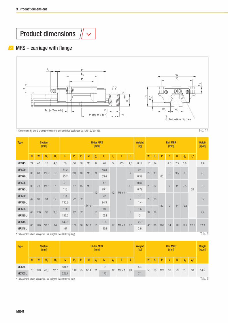
MR-8
3 Product dimensions
MRS – carriage with fl ange
P1
L 1
L*
D
g1
L 3P (Hole pitch)
d
H1
L 2
S
M (4 Threads)
P2
W
W1W2
H2*H
g2
T(Lubrication nipple)
Tab. 5
Fig. 14
Type System
[mm]
Slider MRS
[mm]
Weight
[kg]
Rail MRR
[mm]
Weight
[kg/m]
H W W2
H2
L P2
P1
M g2
L1
L2
T S W1
H1
P d D g1
L3*
MRS15 24 47 16 4,6 69 38 30 M5 8 40 5 ∅3 4,3 0.19 15 14
60
4.5 7.5 5.8
20
1.4
MRS2030 63 21.5 5
81.253 40 M6 9
48.8
12 M6 x 1
70.4
20 18 6 9.5 9 2.6MRS20L 95.7 63.4 0.52
MRS2536 70 23.5 7
9157 45 M8
12
577.8
0.5723 22 7 11 9.5 3.6
MRS25L 113 79.1 0.72
MRS3042 90 31 9
11472 52
M10
727
1.128 26
80 9 14 12.5
5.2MRS30L 135.3 94.3 1.4
MRS3548 100 33 9,5
11482 62 13
808
1.634 29 7.2
MRS35L 139.6 105.8 2
MRS4560 120 37.5 14
142.5100 80 M12 15
10517 M8 x 1 8.5
2.745 38 105 14 20 17.5 22.5 12.3
MRS45L 167 129.8 3.6
Type System
[mm]
Slider MCS
[mm]
Weight
[kg]
Rail MRC
[mm]
Weight
[kg/m]
H W W2
H2
L P2
P1
M g2
L1
L2
T S W1
H1
P d D g1
L3*
MCS5570 140 43,5 12,7
181.5116 95 M14 21
13112 M8 x 1 20
5.453 38 120 16 23 20 30 14.5
MCS55L 223.7 173 7.1
Tab. 6
* Only applies when using max. rail lengths ( see Ordering key)
* Only applies when using max. rail lengths ( see Ordering key)
Product dimensions
* Dimensions H2 and L change when using end and side seals (see pg. MR-15, Tab. 15).

MR-9
Mono Rail
MRS…W – carriage without fl ange
P1
L1
L*
D
g1
H1
dL 3P (Hole pitch)
S
L 2
g2
M (4 Threads)
P2
W
W1W2
HH
2*
T(Lubrication nipple)
Fig. 15
Tab. 7
Type System
[mm]
Slider MRS
[mm]
Weight
[kg]
Rail MRR
[mm]
Weight
[kg/m]
H W W2
H2
L P2
P1
M g2
L1
L2
T S W1
H1
P d D g1
L3*
MRS15W 28 34 9.5 4,6 69 26 26 M4 6.4 40 5 ∅3 8,3 0.21 15 14
60
4.5 7.5 5.8
20
1.4
MRS20W30 44 12 5
81.232
36M5 8
48.8
12 M6 x 1
70.31
20 18 6 9.5 9 2.6MRS20LW 95.7 50 63.4 0.47
MRS25W40 48 12.5 7
9135
35M6 9.6
5711.8
0.4523 22 7 11 9.5 3.6
MRS25LW 113 50 79.1 0.56
MRS30W45 60 16 9
11440
40
M8 12.8
7210
0.9128 26
80 9 14 12.5
5.2MRS30LW 135.3 60 94.3 1.2
MRS35W55 70 18 9,5
11450
50 8015
1.534 29 7.2
MRS35LW 139.6 72 105.8 1.9
MRS45W70 86 20.5 14
142.560
60M10 16
10517 M8 x 1 18.5
2.345 38 105 14 20 17.5 22.5 12.3
MRS45LW 167 80 129.8 2.8
Type System
[mm]
Slider MCS
[mm]
Weight
[kg]
Rail MRC
[mm]
Weight
[kg/m]
H W W2
H2
L P2
P1
M g2
L1
L2
T S W1
H1
P d D g1
L3*
MCS55W 80 100 23.5 12.7 181.5 75 75 M12 19 131 12 M8 x 1 30 5.2 53 38 120 16 23 20 30 14.5
Tab. 8
* Only applies when using max. rail lengths ( see Ordering key)
* Only applies when using max. rail lengths ( see Ordering key)
* Dimensions H2 and L change when using end and side seals (see pg. MR-15, Tab. 15).
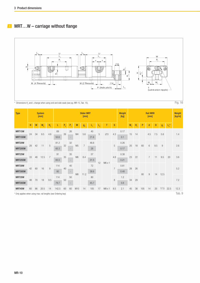
MR-10
3 Product dimensions
MRT…W – carriage without fl ange
P1
L 1
L*
= =
L 1
D
g1
H1
d
L 3P (Hole pitch)
L*L 2
S
M (4 Threads)
g2
M (2 Threads)
L 2
P2
W
W1W2
H2*H
T(Lubrication nipple)
Fig. 16
Type System
[mm]
Slider MRT
[mm]
Weight
[kg]
Rail MRR
[mm]
Weight
[kg/m]
H W W2
H2
L P2
P1
M g2
L1
L2
T S W1
H1
P d D g1
L3*
MRT15W24 34 9.5 4.6
6926
26M4 5.6
405 ∅3 4.3
0.1715 14
60
4.5 7.5 5.8
20
1.4MRT15SW 50.6 - 21.6 0.1
MRT20W28 42 11 5
81.232
32M5 7
48.8
12 M6 x 1
50.26
20 18 6 9.5 9 2.6MRT20SW 60.3 - 28 0.17
MRT25W33 48 12.5 7
9135
35M6 8.4
574.8
0.3823 22 7 11 9.5 3.6
MRT25SW 65.5 - 31.5 0.21
MRT30W42 60 16 9
11440
40
M8 11.2
727
0.8128 26
80 9 14 12.5
5.2MRT30SW 80 - 38.6 0.48
MRT35W48 70 18 9.5
11450
50 808
1.234 29 7.2
MRT35SW 79.7 - 45.7 0.8
MRT45W 60 86 20.5 14 142.5 60 60 M10 14 105 17 M8 x 1 8.5 2.1 45 38 105 14 20 17.5 22.5 12.3
Tab. 9
* Dimensions H2 and L change when using end and side seals (see pg. MR-15, Tab. 15).
* Only applies when using max. rail lengths ( see Ordering key)

MR-11
Mono Rail3 Product dimensions
MRR...F – rails mounted from below
Rail type W1
[mm]
H1
[mm]
L3*
[mm]
P
[mm]
F g1
[mm]
MRR15...F 15 14
20
60
M5 8
MRR20...F 20 18M6
10
MRR25...F 23 22 12
MRR30...F 28 2680 M8
15
MRR35...F 34 29 17
MRR45...F 45 38 22.5 105 M12 24
Fig. 17
Tab. 10
H1
L3 P (Hole pitch) F (Threads) W1
g1
* Only applies when using max. rail lengths ( see Ordering key )

MR-12
Type System
[mm]
H W W2
H2
MR07MN 8 17 5 6.5
MR09MN 10 20 5.5 7.8
MR12MN 13 27 7.5 10
MR15MN 16 32 8.5 12
Miniature Mono Rail standard width
Fig. 18
Tab. 11
Type Slider
[mm]
Rail
[mm]
L P2
P1
M g2
L1
T S Ø Weight
[kg]
W1
H1
P d D g1
Weight
[kg/m]
MR07MN 23.7 12 8 M2 2.5 14.3 2.8 1.6 1.1 0.008 7 4.7 15 2.4 4.2 2.3 0.215
MR09MN 30.6 15 10 M3 3.0 20.5 3.3 2.2 1.3 0.018 9 5.5 20 3.5 6 3.5 0.301
MR12MN 35.4 20 15 M3 3.5 22.0 4.3 3.2 1.3 0.034 12 7.5 25 3.5 6 4.5 0.602
MR15MN 43.0 25 20 M3 5.5 27.0 4.3 3.3 1.8 0.061 15 9.5 40 3.5 6 4.5 0.93
Tab. 12
3 Product dimensions
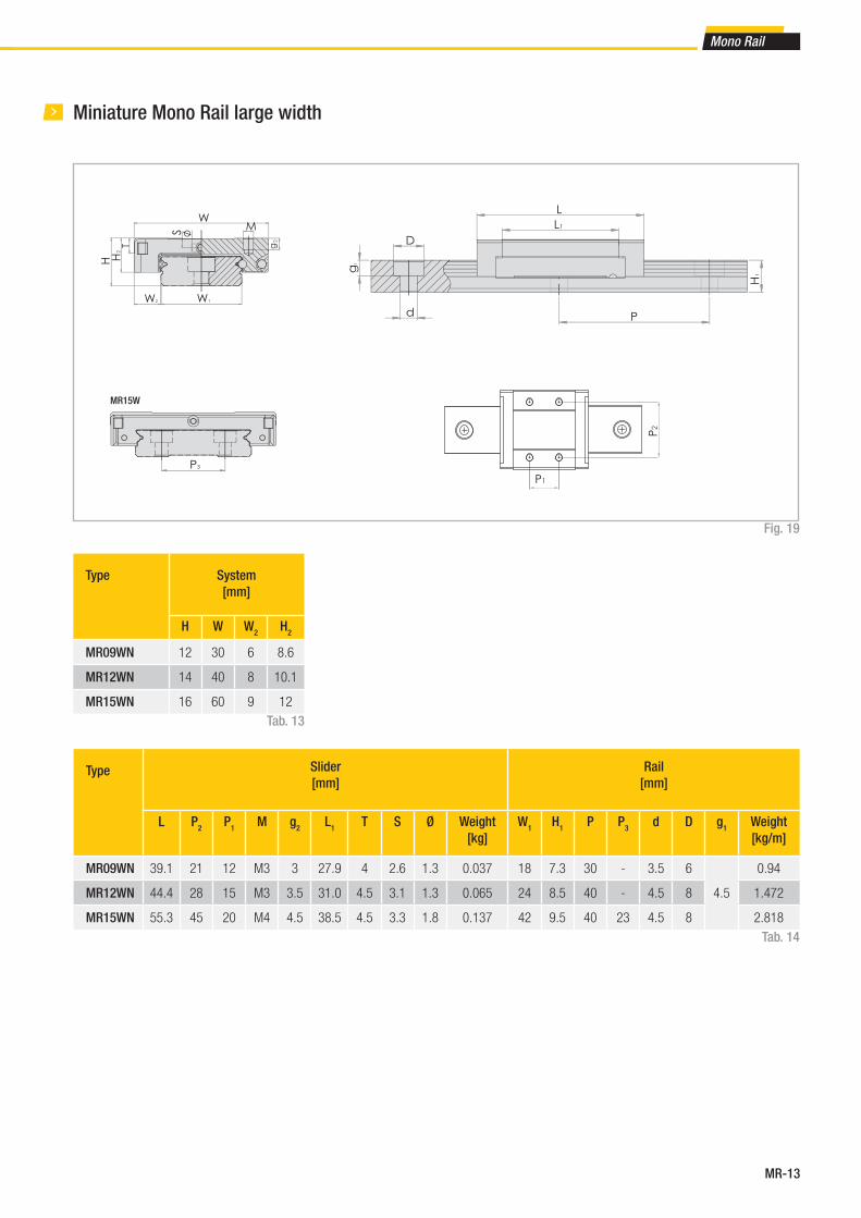
MR-13
Mono Rail
Type System
[mm]
H W W2
H2
MR09WN 12 30 6 8.6
MR12WN 14 40 8 10.1
MR15WN 16 60 9 12
Miniature Mono Rail large width
Fig. 19
Tab. 13
Type Slider
[mm]
Rail
[mm]
L P2
P1
M g2
L1
T S Ø Weight
[kg]
W1
H1
P P3
d D g1
Weight
[kg/m]
MR09WN 39.1 21 12 M3 3 27.9 4 2.6 1.3 0.037 18 7.3 30 - 3.5 6
4.5
0.94
MR12WN 44.4 28 15 M3 3.5 31.0 4.5 3.1 1.3 0.065 24 8.5 40 - 4.5 8 1.472
MR15WN 55.3 45 20 M4 4.5 38.5 4.5 3.3 1.8 0.137 42 9.5 40 23 4.5 8 2.818
Tab. 14
MR15W
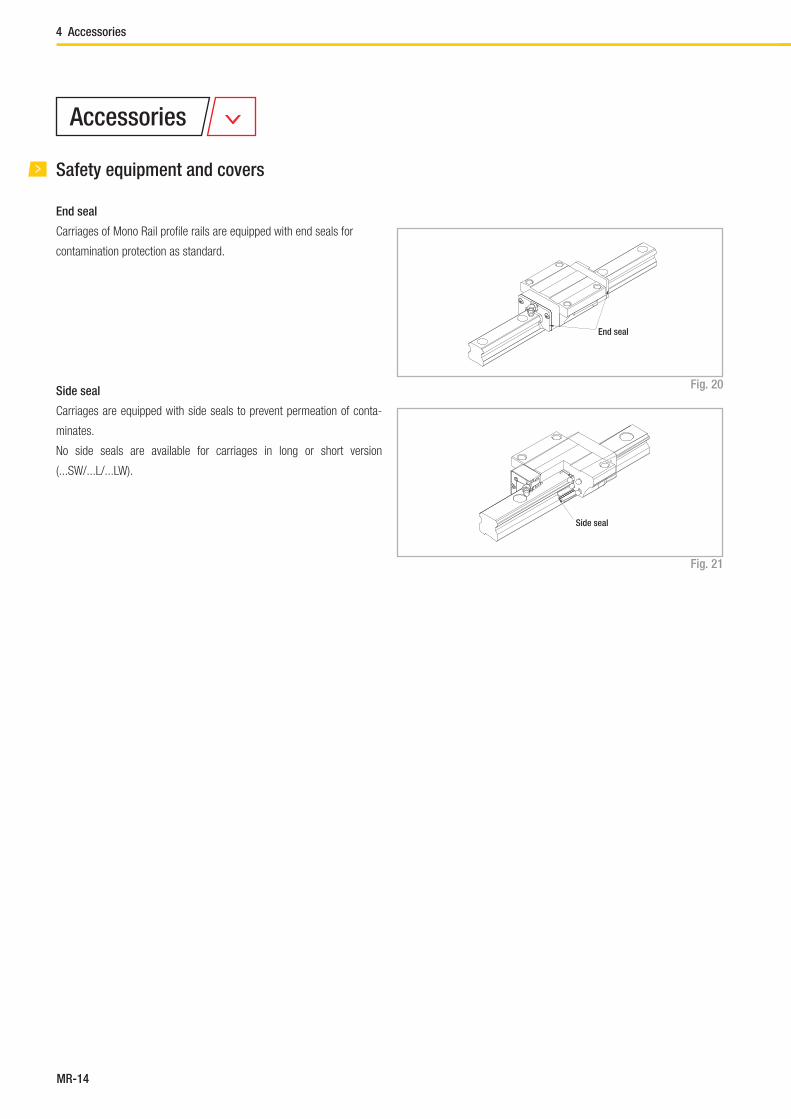
MR-14
Fig. 20
Fig. 21
Safety equipment and covers
End seal
Carriages of Mono Rail profi le rails are equipped with end seals for
contamination protection as standard.
Side seal
Carriages are equipped with side seals to prevent permeation of conta-
minates.
No side seals are available for carriages in long or short version
(...SW/...L/...LW).
End seal
Side seal
Accessories
4 Accessories

MR-15
Mono Rail
Seal variants:
A: Carriage with end and side seal
Tab. 15
1 No side seals are available for carriages in long or short version (...SW/...L/...LW)
* For comparison see Chapter 3 Product dimensions, pg. MR-8ff
Changes in fl oor clearance and length of sliders by corresponding seal variant
Seal variant A A
Slider type1 Size Changed dimension
H2*
[mm]
Changed length
L*
[mm]
MRS
MRS...W
MRT...W
15 2.5 73
20 2.9 85
25 4.9 94.7
30 6.9 117
35 7.6 118
45 12.05 146.7
MCS
MCS...W55 - -
MRS...L
MRS...LW
20 - -
25 - -
30 - -
35 - -
45 - -
MCS...L 55 - -
MRT...SW
15 - -
20 - -
25 - -
30 - -
35 - -

MR-16
Metal cover strip
Fig. 22
Tab. 16
Size Width
[mm]
15 10
20 13
25 15
30 20
35 24
45 32
55 38
Flush cap
Metal debris and other foreign substance can collect in the fi xing holes of
the rails and thus end up the carriage.
To prevent penetration of contamination in the carriage, the fi xing holes
should be capped with perforated caps fl ush with the rail surface.
Flush caps are made of wear and oil resistant synthetic resin. Various
sizes of perforated caps for the counter sunk holes for hexagon socket
bolts M3 to M22 are included as standard in the scope of supply.
Flush caps are driven in fl ush with the rail surface with light hammer taps
using a fl at piece of metal (see fi g. 23).
Fig. 23
30
A rail cover strip made of corrosion resistant steel is available to improve
the seal after guide rail installation. The metal cover strip is 0.3 mm wide
and can have a maximum length of 50 m.Cover strip
Handle
Rail end
clamp
Plastic hammer
Flat piece of metal
4 Accessories

MR-17
Mono Rail
Clamping elements
Mono Rail profi le rails can be secured with manual or pneumatic clamping
elements. Areas of application are:
■ Table cross beams and sliding beds
■ Width adjustment, stops
■ Positioning of optical equipment and measuring tables
Manual clamp elements HK
The HK series is a manually activated clamping element.
Contact profi les press synchronously on the free surfaces of the profi le rail
by using the freely adjustable clamping lever.
The fl oating mounted contact profi les guarantee symmetrical introduction
of force on the guide rail.
Special characteristics of the clamping elements HK:
■ Simple and safe design
■ Floating contact profi le
■ Precise positioning
■ Holding force up to 2,000 N
Variants:
An additional adapter plate must be used depending on the height of the
carriage ( see pg. MR-20, tab. 19 ).
Activation:
Standard with hand lever, further activation options, e.g. using DIN 912
screw, possible on request.
Pneumatic clamp elements MK / MKS
The patented wedge slide gear puts into effect high holding forces. The
pressurised medium moves the wedge slide gear in the longitudinal di-
rection.
Contact profi les press with high force on the free surfaces of the profi le
rail by the resulting cross movement. MK is an element that closes with
pneumatic pressure. The custom design MKS closes with spring energy
storage and is opened via air impingement.
Special characteristics of clamp elements MK / MKS:
■ Short shape
■ High clamp forces
■ Precise positioning
■ High axial and horizontal rigidity
Areas of application of MK:
■ Positioning axes
■ Setting vertical axes
■ Positioning lifting gear
■ Clamping machine tables
Variants:
An additional adapter plate must be used depending on the height of the
carriage ( see pg. MR-20, tab. 20 ).
Connection options:
The basic MK / MKS series versions are equipped with air connections on
both sides, i.e. the factory default settings air connections and the ventila-
tion fi lter can be exchanged to the opposite side surfaces.
Custom design MKS opens with impingement of an air pressure of
> 5.5 bar.
Areas of application of MKS:
■ Clamping with drop in pressure (Normally Open)
■ Clamping without power required (Normally Closed)
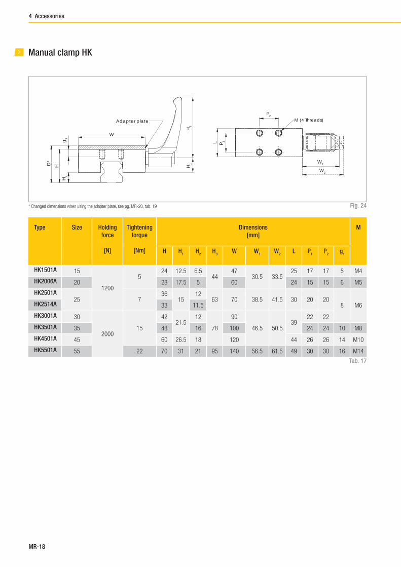
MR-18
Fig. 24
Manual clamp HK
Tab. 17
W
HH
2
D*
g1
H1
H3
Adapter plate
P2
P 1L
W1
W2
M (4 Threads)
* Changed dimensions when using the adapter plate, see pg. MR-20, tab. 19
Type Size Holding
force
[N]
Tightening
torque
[Nm]
Dimensions
[mm]
M
H H1
H2
H3
W W1
W2
L P1
P2
g1
HK1501A 15
1200
524 12.5 6.5
4447
30.5 33.525 17 17 5 M4
HK2006A 20 28 17.5 5 60 24 15 15 6 M5
HK2501A25 7
3615
1263 70 38.5 41.5 30 20 20
8 M6HK2514A 33 11.5
HK3001A 30
200015
4221.5
12
78
90
46.5 50.539
22 22
HK3501A 35 48 16 100 24 24 10 M8
HK4501A 45 60 26.5 18 120 44 26 26 14 M10
HK5501A 55 22 70 31 21 95 140 56.5 61.5 49 30 30 16 M14
4 Accessories
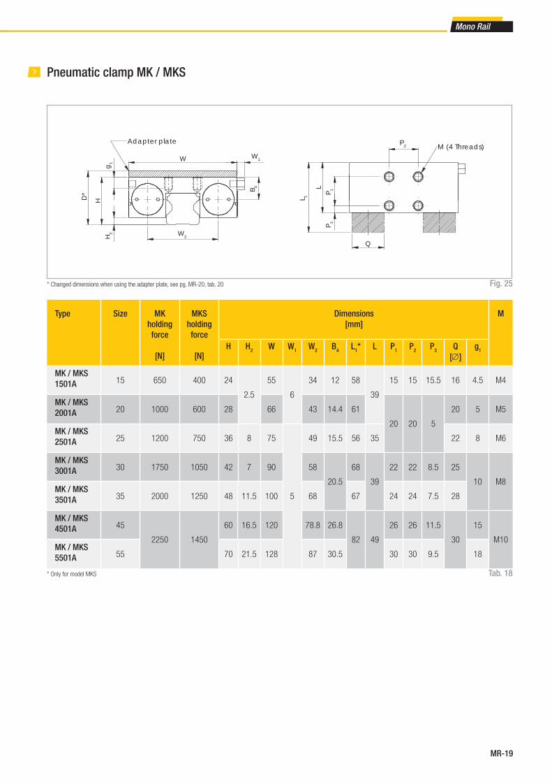
MR-19
Mono Rail
Pneumatic clamp MK / MKS
Fig. 25
Tab. 18
* Changed dimensions when using the adapter plate, see pg. MR-20, tab. 20
W W1
H2
D*
H
W2
B 4
g1
Adapter plate
LP 1
P 3
P2
L 1
Q
M (4 Threads)
* Only for model MKS
Type Size MK
holding
force
[N]
MKS
holding
force
[N]
Dimensions
[mm]
M
H H2
W W1
W2
B4
L1* L P
1P
2P
3Q
[∅]
g1
MK / MKS
1501A 15 650 400 24
2.5
55
6
34 12 58
39
15 15 15.5 16 4.5 M4
MK / MKS
2001A 20 1000 600 28 66 43 14.4 61
20 20 5
20 5 M5
MK / MKS
2501A 25 1200 750 36 8 75
5
49 15.5 56 35 22 8 M6
MK / MKS
3001A 30 1750 1050 42 7 90 58
20.5
68
39
22 22 8.5 25
10 M8MK / MKS
3501A 35 2000 1250 48 11.5 100 68 67 24 24 7.5 28
MK / MKS
4501A 45
2250 1450
60 16.5 120 78.8 26.8
82 49
26 26 11.5
30
15
M10MK / MKS
5501A 55 70 21.5 128 87 30.5 30 30 9.5 18

MR-20
Adapter plate
For HK clamps
Clamp Size Slider type Adapter plate D
HK1501A 15MRS, MRT...W, MRT...SW - 24
MRS...W PHK 15-4 28
HK2006A 20MRT...W, MRT...SW - 28
MRS, MRS...L, MRS...W, MRS...LW PHK 20-2 30
HK2514A
25
MRT...W, MRT...SW - 33
HK2501AMRS, MRS...L, - 36
MRS...W, MRS...LW PHK 25-4 40
HK3001A 30MRS, MRS...L, MRT...W, MRT...SW - 42
MRS...W, MRS...LW PHK 30-3 45
HK3501A 35MRS, MRS...L, MRT...W, MRT...SW - 48
MRS...W, MRS...LW PMK 35-7 55
HK4501A 45MRS, MRS...L, MRT...W - 60
MRS...W, MRS...LW PHK 45-10 70
On request
55
- 68
HK5501AMCS, MCS...L - 70
MCS...W PHK 55-10 80
Tab. 19
For MK / MKS clamps
Clamp Size Slider type Adapter plate D
MK / MKS
1501A15
MRS, MRT...W, MRT...SW - 24
MRS...W PMK 15-4 28
MK / MKS
2001A20
MRT...W, MRT...SW - 28
MRS, MRS...L, MRS...W, MRS...LW PMK 20-2 30
On request
25
MRT...W, MRT...SW - 33
MK / MKS
2501A
MRS, MRS...L, MRZ - 36
MRS...W, MRS...LW PMK 25-4 40
MK / MKS
3001A30
MRS, MRS...L, MRT...W, MRT...SW - 42
MRS...W, MRS...LW PMK 30-3 45
MK / MKS
3501A35
MRS, MRS...L, MRT...W, MRT...SW - 48
MRS...W, MRS...LW PMK 35-7 55
MK / MKS
4501A45
MRS, MRS...L, MRT...W - 60
MRS...W, MRS...LW PMK 45-10 70
On request
55
- 68
MK / MKS
5501A
MCS, MCS...L - 70
MCS...W PMK 55-10 80
Tab. 20
4 Accessories

MR-21
Mono Rail
Fig. 27
H
WA B
CD
WH
A B
CD
Mono Rail precision
Precision means the guide accuracy or the maximal deviation of the car-
riage based on the side and support surfaces during the movement along
the rails.
Fig. 26
Schienenlänge (mm)
Norm
Hoch
Präz
Normal (N)
High (H)
Precise (P)
Rail length (mm)
Δ C (μm)
Δ D (μm)
Technical instructions
Precision class
[mm]
Normal
[N]
High
[H]
Precise
[P]
Height tolerance H± 0.1 ± 0.04 0 to -0.04
Side tolerance W
Height difference (Δ H)0,03 0,02 0,01
Width difference (Δ W)
Guide accuracy of raceway C based on
surface AΔC see graph in fig. 27
Guide accuracy of raceway D based on
surface BΔD see graph in fig. 27
Tab. 21
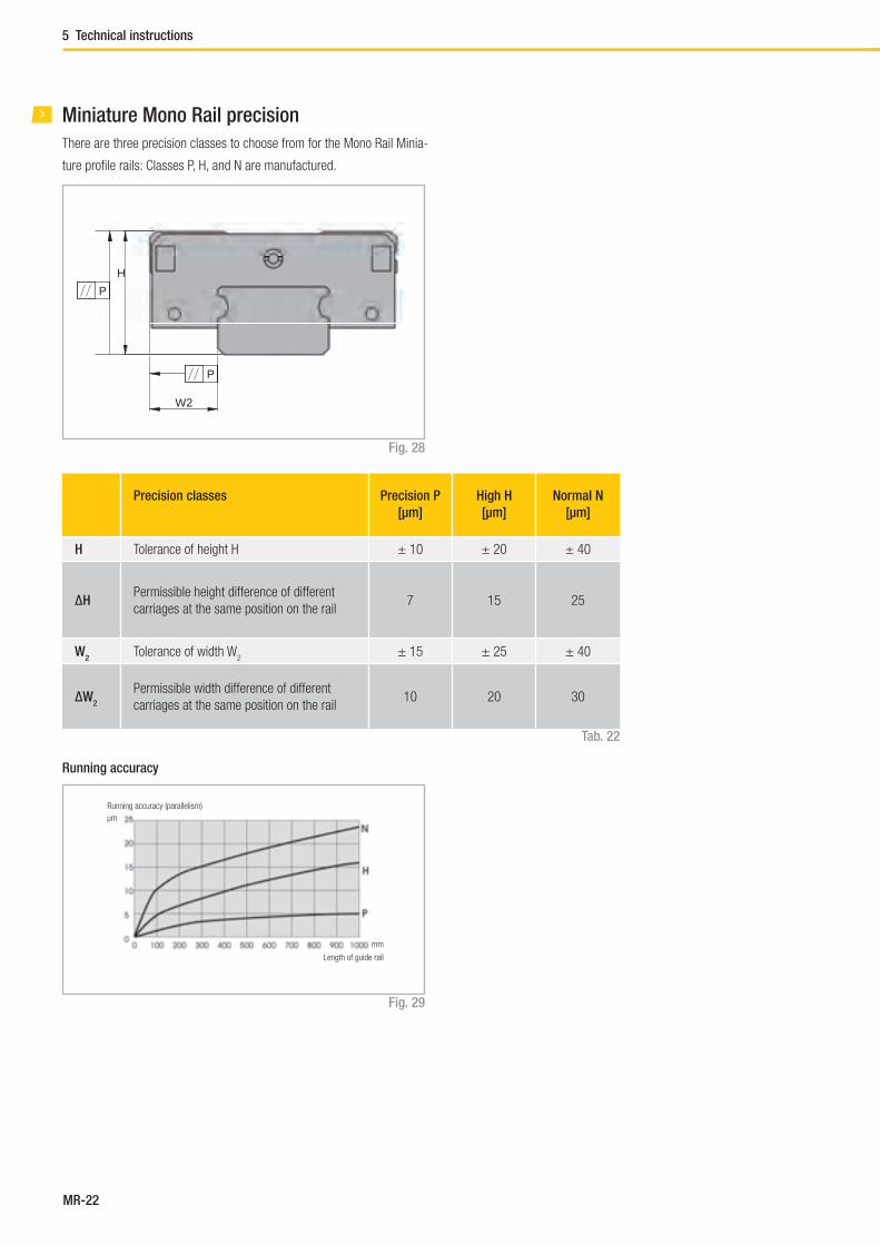
MR-22
W2
H
P
P
Miniature Mono Rail precision
There are three precision classes to choose from for the Mono Rail Minia-
ture profi le rails: Classes P, H, and N are manufactured.
Running accuracy
Running accuracy (parallelism)
Length of guide rail
Precision classes Precision P
[μm]
High H
[μm]
Normal N
[μm]
H Tolerance of height H ± 10 ± 20 ± 40
ΔHPermissible height difference of different
carriages at the same position on the rail7 15 25
W2
Tolerance of width W2
± 15 ± 25 ± 40
ΔW2
Permissible width difference of different
carriages at the same position on the rail10 20 30
Fig. 28
Fig. 29
Tab. 22
μm
mm
5 Technical instructions
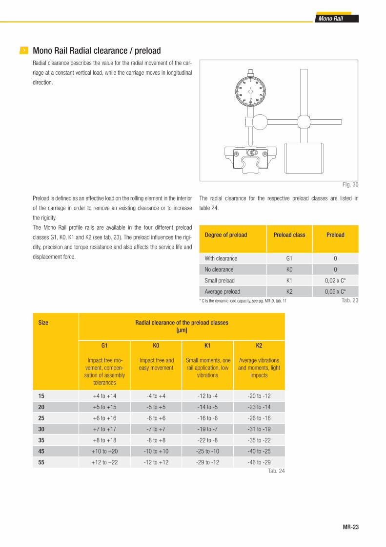
MR-23
Mono Rail
Mono Rail Radial clearance / preload
The radial clearance for the respective preload classes are listed in
table 24.
Degree of preload Preload class Preload
With clearance G1 0
No clearance K0 0
Small preload K1 0,02 x C*
Average preload K2 0,05 x C*
Tab. 23* C is the dynamic load capacity, see pg. MR-9, tab. 1f
Radial clearance describes the value for the radial movement of the car-
riage at a constant vertical load, while the carriage moves in longitudinal
direction.
Fig. 30
Preload is defi ned as an effective load on the rolling element in the interior
of the carriage in order to remove an existing clearance or to increase
the rigidity.
The Mono Rail profi le rails are available in the four different preload
classes G1, K0, K1 and K2 ( see tab. 23 ). The preload infl uences the rigi-
dity, precision and torque resistance and also affects the service life and
displacement force.
Size Radial clearance of the preload classes
[μm]
G1
Impact free mo-
vement, compen-
sation of assembly
tolerances
K0
Impact free and
easy movement
K1
Small moments, one
rail application, low
vibrations
K2
Average vibrations
and moments, light
impacts
15 +4 to +14 -4 to +4 -12 to -4 -20 to -12
20 +5 to +15 -5 to +5 -14 to -5 -23 to -14
25 +6 to +16 -6 to +6 -16 to -6 -26 to -16
30 +7 to +17 -7 to +7 -19 to -7 -31 to -19
35 +8 to +18 -8 to +8 -22 to -8 -35 to -22
45 +10 to +20 -10 to +10 -25 to -10 -40 to -25
55 +12 to +22 -12 to +12 -29 to -12 -46 to -29
Tab. 24

MR-24
Miniature Mono Rail Preload
The Mono Rail Miniature profi le rails are available in the three different
preload classes V0, V
S and V
1 (see table 25). The preload infl uences the
rigidity, precision and torque resistance and also affects the product ser-
vice life and displacement force.
TypePreload classes
Small clearance
Very quiet running
V0
[μm]
Standard
Very quiet and precise
running
VS
[μm]
Small preload
High rigidity, vibration
reduced, high precision,
good load balance
V1
[μm]
MR07 from +5 to +2 from +1 to -2 from -2 to -4
MR09 from +5 to +2 from +2 to -2 from -2 to -5
MR12 from +6 to +2 from +2 to -2 from -2 to -5
MR15 from +7 to +2 from +2 to -3 from -2 to -6
Tab. 25
5 Technical instructions

MR-25
Mono Rail
Mono Rail lubrication
Profi le rails must generally be lubricated before commissioning. They can
be lubricated with oil or grease.
The correct lubricant selection has a large infl uence on the service life and
the function of the profi le rail, insuffi cient lubrication and tribocorrosion
can ultimately lead to total failure.
Important instructions for lubrication
■ Mono Rail profi le rails must be lubricated for operation.
■ The carriage must be moved back and forth during lubrication.
■ The lubricant is inserted through a lubrication nipple.
■ There should be a thin fi lm of lubricant on the rail surface at all times.
■ Please inform us in advance if the guides are to be used in acid or base
containing environments or in clean rooms.
Grease lubrication
We recommend the use of a lithium emulsifi ed lubricant NLGI Class 2 for
lubrication.
Oil lubrication
We recommend a synthetic oil for operating temperatures between 0 °C
and +70 °C. For application-specifi c custom lubrication, please contact
Rollon technical support.
Relubrication
■ Relubrication of the system must be done before the lubricant used is
dirty or shows discolouration.
■ Relubrication is performed at operating temperature. The carriage
must be moved back and forth during relubrication.
■ If the stroke is <2 or >15 times the carriage length, the lubrication
intervals should be more often.
Lubrication intervals
Operating speed, stroke length and ambient conditions infl uence the
selection of time between lubrication intervals. Establishing a safe lubri-
cation interval is based exclusively on the experienced practiced values
determined on site. However, a lubrication interval should not be longer
than one year in any case.
■ Primary lubricated systems have an increased displacement resi-
stance.
■ Please contact Rollon technical support if the rail will be oriented ver-
tically.
■ If the stroke is <2 or >15 times the carriage length, the lubrication
intervals should be shortened.
Anticorrosive protection
There are numerous application-specifi c surface treatments available for
profi le rails of the Mono Rail product family.
For more information please contact Rollon technical support. All linear
rails of the Miniature Mono Rail series are made of stainless steel.
As well as reducing friction and wear, lubricants also serve as sealant,
noise damper and corrosion protection for the linear guide. Different lubri-
cants for special applications are available upon request.
For more information please contact Rollon technical support.
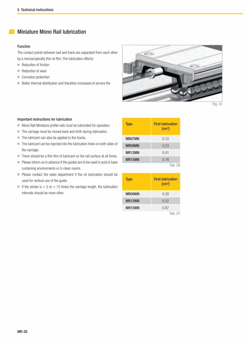
MR-26
Function
The contact points between ball and track are separated from each other
by a microscopically thin oil fi lm. The lubrication effects:
■ Reduction of friction
■ Reduction of wear
■ Corrosion protection
■ Better thermal distribution and therefore increased of service life
Miniature Mono Rail lubrication
Fig. 31
Important instructions for lubrication
■ Mono Rail Miniature profi le rails must be lubricated for operation.
■ The carriage must be moved back and forth during lubrication.
■ The lubricant can also be applied to the tracks.
■ The lubricant can be injected into the lubrication holes on both sides of
the carriage.
■ There should be a thin fi lm of lubricant on the rail surface at all times.
■ Please inform us in advance if the guides are to be used in acid or base
containing environments or in clean rooms.
■ Please contact the sales department if the oil lubrication should be
used for vertical use of the guide.
■ If the stroke is < 2 or > 15 times the carriage length, the lubrication
intervals should be more often.
Type First lubrication
[cm3]
MR07MN 0.12
MR09MN 0.23
MR12MN 0.41
MR15MN 0.78
Type First lubrication
[cm3]
MR09WN 0.30
MR12WN 0.52
MR15WN 0.87
Tab. 26
Tab. 27
5 Technical instructions
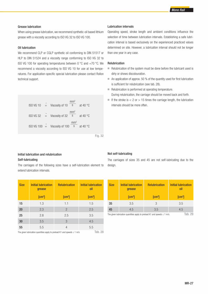
MR-27
Mono Rail
Lubrication intervals
Operating speed, stroke length and ambient conditions infl uence the
selection of time between lubrication intervals. Establishing a safe lubri-
cation interval is based exclusively on the experienced practiced values
determined on site. However, a lubrication interval should not be longer
than one year in any case.
Relubrication
■ Relubrication of the system must be done before the lubricant used is
dirty or shows discolouration.
■ An application of approx. 50 % of the quantity used for fi rst lubrication
is suffi cient for relubrication ( see tab. 28).
■ Relubrication is performed at operating temperature.
During relubrication, the carriage should be moved back and forth.
■ If the stroke is < 2 or > 15 times the carriage length, the lubrication
intervals should be more often.
Oil lubrication
We recommend CLP or CGLP synthetic oil conforming to DIN 51517 or
HLP to DIN 51524 and a viscosity range conforming to ISO VG 32 to
ISO VG 100 for operating temperatures between 0 °C and +70 °C. We
recommend a viscosity according to ISO VG 10 for use at low tempe-
ratures. For application-specifi c special lubrication please contact Rollon
technical support.
Grease lubrication
When using grease lubrication, we recommend synthetic-oil based lithium
grease with a viscosity according to ISO VG 32 to ISO VG 100.
Fig. 32
ISO VG 10 = Viscosity of 10 at 40 °C
ISO VG 32 = Viscosity of 32 at 40 °C
ISO VG 100 = Viscosity of 100 at 40 °C
‹ mm2
s
mm2
s
‹‹ mm2
s
Size Initial lubrication
grease
[cm3]
Relubrication
[cm3]
Initial lubrication
oil
[cm3]
15 1.3 1.1 1.5
20 2.3 2 2.5
25 2.8 2.5 3.5
30 3.5 3 4.5
55 5.5 4 5.5
Size Initial lubrication
grease
[cm3]
Relubrication
[cm3]
Initial lubrication
oil
[cm3]
35 3.5 3 3.5
45 4.5 3.5 4.5
Tab. 29
Tab. 28
Self-lubricating
Not self-lubricatingInitial lubrication and relubrication
The carriages of the following sizes have a self-lubrication element to
extend lubrication intervals.
The carriages of sizes 35 and 45 are not self-lubricating due to the
design.
The given lubrication quantities apply to preload K1 and speeds ≤ 1 m/s
The given lubrication quantities apply to preload K1 and speeds ≤ 1 m/s
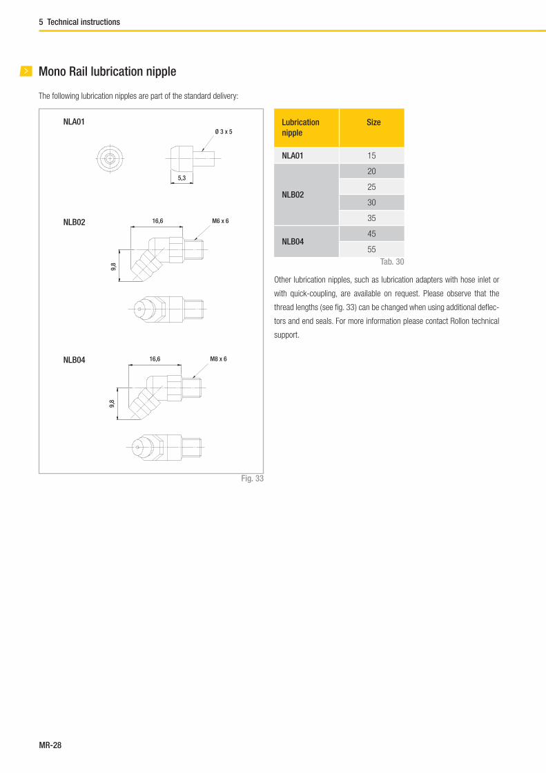
MR-28
Mono Rail lubrication nipple
NLB02
NLB04
Fig. 33
Tab. 30
The following lubrication nipples are part of the standard delivery:
Other lubrication nipples, such as lubrication adapters with hose inlet or
with quick-coupling, are available on request. Please observe that the
thread lengths ( see fi g. 33 ) can be changed when using additional defl ec-
tors and end seals. For more information please contact Rollon technical
support.
NLA01 Lubrication
nipple
Size
NLA01 15
NLB02
20
25
30
35
NLB0445
55
Ø 3 x 5
5,3
16,6
9,8
M6 x 6
16,6
9,8
M8 x 6
5 Technical instructions

MR-29
Mono Rail
Friction / displacement resistanceMono Rail profi le rails have a low friction characteristic and thus low dis-
placement resistance. The low start-up friction (breakaway force) is al-
most identical to the moving friction (running resistance).
The displacement resistance is dependent upon several factors:
■ Friction of the sealing system
■ Friction of the balls with each other
■ Friction between balls and redirection
■ Rolling resistance of the balls in the running grooves
■ Resistance of lubricant in the carriage
■ Resistance by contamination in the lubricant
■ Preload for increase of rigidity
■ Moment load
Mono Rail profi le rails have a coeffi cient of friction of approx.
μ = 0.002 - 0.003.
Fm = μ · F + f
Fm = Displacement resistance ( N )
F = Load ( N )
μ = Coeffi cient of friction
f = Resistance of the seals ( N )
Fig. 35
Tab. 31
Type f
[N]
MRS15 0.15
MRS20 0.2
MRS25 0.35
MRS30 0.7
MRS35 0.8
MRS45 0.9
MCS55 1.0
Resistance of the seals
Fig. 34
Displacement resistance
The following formula is used for general approximate calculation of the
displacement resistance. Please note that the level of preload or the visco-
sity of the lubricant used can also infl uence the displacement resistance.
Coeff
icie
nt
of
fric
tion
(μ
)
Loading ratio: (P/C)
P: Loading
C: Dynamic load capacities
0.005
0.010
0.015
2.01.00

MR-30
Mono Rail loading
Fig. 36
Operating conditions S0
Normal operation 1 ~ 2
Loading with vibration or shock effect 2 ~ 3
Loading with strong vibration or impacts ≥ 3
Tab. 32
The safety factor S0 can lie on the lower given limit if the occurring forces
can be determined with suffi cient precision. If shock and vibration are pre-
sent, the higher value should be selected. For dynamic applications higher
safety is required. Please contact Rollon technical support.
Safety factor
The given static load capacity for each carriage represents the maximum
permissible load value, which if exceeded causes permanent deforma-
tions of the raceways and adverse effects of the running properties.
Checking the load must be done as follows:
- through determination of the simultaneously occurring forces and
moments for each carriage
- by comparison of these values with the corresponding load capacities.
The ratio of the actual load to maximum permissible load may be as large
as the reciprocal of the accepted safety factor, S0, at the most.
Fig. 37
The above formulas are valid for a single load case.
If two or more forces are acting simultaneously, please check the following
formula:
P0rad
1
C0rad
S0
≤P
0ax 1
C0ax
S0
≤M
1 1
Mx S
0
≤M
2 1
My S
0
≤M
3 1
Mz S
0
≤
P0rad
= effective radial load (N)
C0rad
= permissible radial load (N)
P0ax
= effective axial load (N)
C0ax
= permissible axial load (N)
M1, M
2, M
3 = external moments ( Nm)
Mx, M
y, M
z = maximum permissible moments
in the different loading directions (Nm)
P0rad
P0ax
M1 M
2 M
3
C0rad
C0ax
Mx M
y M
z
+ + + + ≤1
S0
5 Technical instructions

MR-31
Mono Rail
Static load (P0) and static moment (M
0)
Permissible static load
The permissible static load of the Mono Rail Miniature profi le rail is limited
by:
■ Static load of each linear guide
■ Permissible load of the fi xing screws
■ Permissible load of all components used in the surrounding
construction
■ Static safety factor, which is required by the corresponding
application
The equivalent static load and the static moment are the largest load, or
the largest moment, which are calculated based on formulas 3 and 4.
Static safety factor S0
When observing the static safety factor S0 the Mono Rail Miniature pro-
fi le rails allow a permissible operation and high running precision as is
required for each application. Calculation of the static safety factor S0:
see fi g. 38
S0 static safety factor
C0 static load capacity in loading direction (N)
P0 equivalent static load (N)
M0 static moment in loading direction (Nm)
M equivalent static moment in loading direction (Nm)
Static load capacity C0
The static load capacity C0 of ball recirculating guides is defi ned according
to DIN 636, Part 2 as the only load which gives a Hertzian stress of 4,200
MPa with the existing lubrication between track and balls in the center of
the highest loaded contact surface.
Note: In the loading center, there is a permanent deformation of approx
0.01 % of the ball diameter under this load (according to DIN 636, Part 2).
Miniature Mono Rail loading
S0 = C
0 / P
0 Formula 1 Operating conditions S
0
S0 = M
0 / M
Formula 2 Normal operation 1 ~ 2
P0 = F
max Formula 3 Loading with vibration or shock effect 2 ~ 3
M0 = M
max Formula 4 High precision and smooth running ≥ 3
Fig. 38

MR-32
Equivalent dynamic load and speed
With changing load and speed, these must be considered individually sin-
ce each parameter helps determine the service life.
Equivalent dynamic load
If only the load changes, the equivalent dynamic load can be calculated
with formula 5.
Equivalent speed
If only the speed changes, the equivalent speed is calculated with formula 6.
If speed and load change, the equivalent dynamic load is calculated with
formula 7.
Combined dynamic load
With combined exterior load in an arbitrary angle, the equivalent dynamic
load is calculated with formula 8.
P = 3 –––––––––––––––––––––– Formula 5
v = ––––––––––––––––––– Formula 6
P = 3 –––––––––––––––––––––––––––––
Formula 7
P = | FX | + | F
Y | Formula 8
Formula 9
P = equivalent dynamic load (N)
q = stroke (in %)
F1 = individual load levels (N)
v = average speed (m/min)
v = individual speed levels (m/min)
F = external dynamic load (N)
FY = external dynamic load – vertical (N)
FX = external dynamic load – horizontal (N)
C0 = static load capacity (N)
M1, M
2, M
3 = external moments (Nm)
Mx, M
y, M
z = maximum permissible moments in the different
loading directions (Nm)
q1 · F
13 + q
2 · F
23 + ··· q
n · F
n3
100
q1 · v
1 + q
2 · v
2 + ··· q
n · v
n
100
q1 · v
1 · F
13 + q
2 · v
2 · F
23 + ··· q
n · v
n · F
n3
100
Fig. 39
Dynamic load capacity C
If the dynamic loads work vertically on the last zones with equal size and
direction, the calculated service life of the linear guide can theoretically
reach 100 km piston travel (as per DIN 636, Part 2).
Combined loads in combination with moments
If both loads and moments work on the profi le rails, the equivalent dyna-
mic load is calculated with formula 9. According to DIN 636, Part 1, the
equivalent load should not exceed ½ C.
P = | FX | + | F
Y | + ( + + ) · C
0
| M1|
Mx
| M2|
My
| M3|
Mz
5 Technical instructions

MR-33
Mono Rail
Mono Rail service life
The dynamic load capacity C is a conventional variable used for calcula-
ting the service life. This load corresponds to a nominal service life of 50
km. The relationship between calculated service life Lkm
( in km ), dynamic
load capacity C ( in N ) and equivalent load P ( in N ) is given in the formula
to the right:Fig. 40
fc = contact factor
fi = application coeffi cient
Calculation of service life:
The contact factor fc refers to applications in which several carriages pass
the same rail section. If two or more carriages are moved over the same
point on a rail, the static and dynamic loading values must be multiplied
with the numbers from the table below:
Contact factor fc
Number of
carriages
1 2 3 4 5
fc
1 0.81 0.72 0.66 0.61
Tab. 33
The application coeffi cient fi can be understood as the dynamic safety
factor. Refer to the table below for the values:
Application coeffi cient fi
Operational conditions Speed fi
Neither external impacts nor vibrations Low speed V ≤ 15 m/min. 1 - 1.5
Light impacts or vibrations Average speed 15 < V ≤ 60 m/min. 1.5 - 2
Average and high external impacts or vibrations High speed V > 60 m/min. 2 - 3.5
Tab. 34
The equivalent load P corresponds in its effects to the sum of the forces
and moments working simultaneously on a slider. If these different load
components are known, P results from the equation to the right:
Fig. 41
Lkm
= ( · )3 · 50 km C
P
fc
fi
P = | P0ax
| + | P0rad
| + ( + + ) · C0rad
| M1|
Mx
| M2|
My
| M3|
Mz

MR-34
Miniature Mono Rail service life
An example of a profi le rail or a lot of identical profi le rails under the
same running conditions, which use ordinary materials with normal
manufacturer‘s quality and operating conditions, can reach 90 % of the
calculated service life (as per DIN 636 Part 2). By taking 50 km traverse
as a basis, the dynamic load capacity is usually 20 % over the values as
per DIN. The relationship between the two load capacities can be seen
from formulas 10 and 11.
Calculation of service life
Formulas 12 and 13 are used for calculating the service life, if equivalent
dynamic load and average speed are constant.
C(50)
= 1,26 · C(100)
Formula 10
C(100)
= 0,79 · C(50)
Formula 11
L = ( ––– )3 · 105 Formula 12
Lh = ––––––––––– = ––– · ( ––– )3 Formula 13
C100
P
L
2 · s · n · 60
C100L
PVm
L = service life based on 100,000 (m)
Lh = service life (h)
C = dynamic load capacity (N)
P = equivalent dynamic load (N)
S = stroke length (m)
n = stroke frequency (min -1)
Vm = average speed (m/min)
Fig. 42
5 Technical instructions

MR-35
Mono Rail
SmSm
Lv
Hc
Ground stop surfaceSm
Sm
Lv
Hr
Ground surface
Mono Rail installation instructions
Fig. 43
Size Maximum level of
incline
Sm
[mm]
Maximum height of
rail shoulder
Hr
[mm]
Maximum height of
rail shoulder when
using the side seal
Hr*
[mm]
Maximum height of
slider shoulder
Hc
[mm]
Required bolt
lengths (rails)
Lv
[mm]
150.8
4 1.9 5 M4 x 16
20 4.5 2.4 6 M5 x 20
25
1.2
6 3.9 7 M6 x 25
30 8 5.9 8M8 x 30
35 8.5 6.6 9
451.6
12 10.5 11 M12 x 40
55 13 - 12 M14 x 45
Tab. 35
The given radii and shoulder heights in the table must be observed when
assembling rails and carriages on the stop edges to ensure perfect se-
ating of carriages or raceways.
* For use of various seals, see pg. MR-14, fi g. 21ff

MR-36
The bolt sizes to be used and optimum tightening torques for rail assembly
are listed in the table below ( see tab. 37 ).
The maximum permissible deviations of the rail surfaces for assem-
bly are given in the following drawing ( see fi g. 44 ) and the table below
( see tab. 36 ):
Assembly precision
Fig. 44
Size Permissible tolerance for parallelism p1
[μm]
Permissible tolerance for parallelism p2
[μm]
K2 K1 K0 G1 K2 K1 K0 G1
15 - 1825 35
-
85 130190
20 18 20 50
25 20 22 30 42 70 195
30 27 30 40 55 90 110 170 250
35 30 35 50 68 120 150 210 290
45 35 40 60 85 140 170 250 350
55 45 50 70 95 170 210 300 420
Tab. 36
Bolt Tightening torque Mt
[Nm]
Steel Cast iron Aluminium
M4 4 3 2
M5 9 6 4
M6 14 9 7
M8 30 20 15
M12 118 78 59
M14 157 105 78
p1
p2
Tab. 37
5 Technical instructions

MR-37
Mono Rail
Miniature Mono Rail installation instructions
Shoulder heights and radius of stop edges
Rounding of the stop edges of the surrounding construction should be
made so as to avoid contact with the edges of the carriage and the rail.
Please observe the following table with the information on the radius and
height of the stop surfaces.
Geometric and positional accuracy of the mounting surfaces
Inaccuracies of the mounting surface negatively infl uence the running ac-
curacy and reduce the service life of the Mono Rail Miniature profi le rails.
If the inaccuracies of the mounting surfaces exceed the values calculated
using formulas 14, 15 and 16, the service life is shortened according to
formulas 12 und 13.
Mounting surface
The mounting surface should be ground or milled very fi nely and have a
surface roughness of Ra 1.6.
Dimensions of the stop edges
Type h1
[mm]
r1max
[mm]
h2
[mm]
r2max
[mm]
E
[mm]
MR07M 1.2 0.3 2.8 0.3 1.5
MR09M 1.5 0.3 3 0.3 2.2
MR12M 2.5 0.5 4 0.5 3
MR15M 2.5 0.5 4.5 0.5 4
Type h1
[mm]
r1max
[mm]
h2
[mm]
r2max
[mm]
E
[mm]
MR09W 2.5 0.3 3 0.3 3.4
MR12W 2.5 0.5 4 0.5 3.9
MR15W 2.5 0.5 4.5 0.5 4
Reference surface
Rail: Both sides of the rails can be used as a reference surface without
further marks.
Slider: The reference surface is located across from the running side iden-
tifi ed with a notch mark.
Fig. 45
Tab. 38
Tab. 39
r2
h2
r1
h1
E

MR-38
TypeV
0, V
SV
1
f1 f2 f3 f1 f2 f3
MR07MN 5 11 4 3 10 3
MR09MN 5 11 6 4 10 4
MR12MN 6 13 8 4 12 6
MR15MN 7 11 12 5 10 8
TypeV
0, V
SV
1
f1 f2 f3 f1 f2 f3
MR09WN 2 7 6 2 5 4
MR12WN 3 8 8 2 5 5
MR15WN 2 9 11 1 6 7
e1 (mm) = b (mm) · f1 · 10-4 Formula 14
e2 (mm) = d (mm) · f2 · 10-5 Formula 15
e3 (mm) = f3 · 10-3 Formula 16
Calculation of the positional accuracy
Fig. 46 Fig. 47
Tab. 40
Fig. 48
Tab. 41
Tightening torque for fi xing screws (Nm)
Screw quality
12.9
Steel Cast iron Non-ferrous
metal
M2 0.6 0.4 0.3
M3 1.8 1.3 1
M4 4 2.5 2
Tab. 42
e1
e3
b
d
e2
5 Technical instructions

MR-39
Mono Rail
A A
A1 A1 A2 A2
B1 B1 B2 B2
Guide rails longer than the one part maximum length ( see Ordering key),
are put together from two or more rails.
When putting guide rails together, be sure that the register marks shown
in fi g. 49 are positioning correctly.
These are fabricated axisymmetric for parallel application of composite
guide rails, unless otherwise specifi ed.
Composite rails
Fig. 49
Two rails
Several rails
Comp. L
Comp. L
Joint
Joint marks
Joint marks
Joint marks
Joint marks
Joint marks
Joint
Joint
Joint
Joint

MR-40
Adjacent construction
Sub-constructionSet screw (rail)
Set screw (slider)
Fixing guide rails:
( 1) Whet the assembly surface with a whetstone and also remove burrs,
unevenness and dirt ( see fi g. 51 ).
Note: All linear guides are preserved with anticorrosion oil at the factory.
This protection must be removed before installation.
In doing so, please ensure that the surfaces are coated with low-viscosity
oil for the purpose of further protection against corrosion.
( 2 ) Carefully lay the guide rail on the assembly surface ( see fi g. 52 ) and
slightly tighten the fi xing screws so that the guide rail lightly touches the
assembly surface ( align the guide rail along the shoulder edge of the as-
sembly surface, see fi g. 53 ).
Note: The fi xing screws of the linear guide must be clean. Check if the
fi xing holes are located in the correct place when you insert the bolts. A
forced tightening of a fi xing screw in an offset hole can negatively affect
accuracy.
Assembly process
Fig. 50
Fig. 53
Fig. 52
Fig. 51
5 Technical instructions
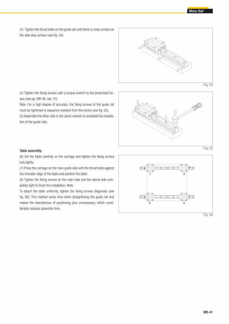
MR-41
Mono Rail
( 3 ) Tighten the thrust bolts on the guide rail until there is close contact on
the side stop surface ( see fi g. 54 ).
( 4 ) Tighten the fi xing screws with a torque wrench to the prescribed tor-
que ( see pg. MR-36, tab. 37).
Note: For a high degree of accuracy, the fi xing screws of the guide rail
must be tightened in sequence outward from the centre ( see fi g. 55 ).
( 5 ) Assemble the other rails in the same manner to complete the installa-
tion of the guide rails.
Table assembly:
( 6 ) Set the table carefully on the carriage and tighten the fi xing screws
only lightly.
( 7 ) Press the carriage on the main guide side with the thrust bolts against
the shoulder edge of the table and position the table.
( 8 ) Tighten the fi xing screws on the main side and the lateral side com-
pletely tight to fi nish the installation. Note:
To attach the table uniformly, tighten the fi xing screws diagonally ( see
fi g. 56 ). This method saves time when straightening the guide rail and
makes the manufacture of positioning pins unnecessary, which consi-
derably reduces assembly time.
Fig. 56
Fig. 54
1
2
4
3
Fig. 55
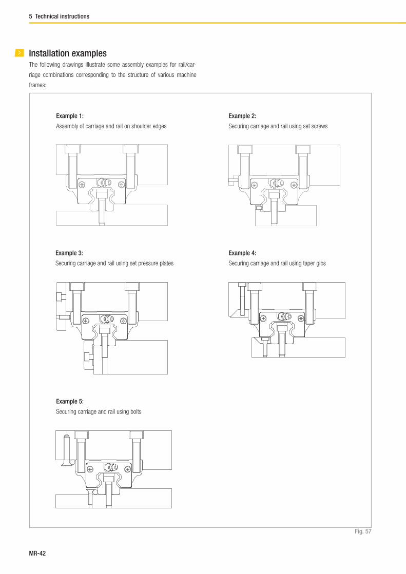
MR-42
Installation examplesThe following drawings illustrate some assembly examples for rail/car-
riage combinations corresponding to the structure of various machine
frames:
Example 1:
Assembly of carriage and rail on shoulder edges
Example 3:
Securing carriage and rail using set pressure plates
Example 5:
Securing carriage and rail using bolts
Example 2:
Securing carriage and rail using set screws
Example 4:
Securing carriage and rail using taper gibs
Fig. 57
5 Technical instructions

MR-43
Mono Rail
MRR 20 6860 N F T HC
Surface coating for rail optional
see pg. MR-25, Anticorrosive protection
Joint processed rails optional see pg. MR-39, Composite rails
Rails bolted from below, optional see pg. MR-11
Precision class see pg. MR-21, tab. 21
Total rail length
Size
Rail type
Rail
Rail / Mono Rail slider system
Ordering example: MRR20-06850-NF-T-NIC
Rail composition: 1x2920+1x3940 (only for joint processed rails)
Hole pattern: 10-48x60-30//30-65x60-10 (please always specify the hole pattern separately)
Notes on ordering: The rail lengths are always indicated as 5 digits with 0 prefi xes
Ordering example: MRS30W-H-K1-A-HC-1-05960F-T-NIC
Rail composition: 1x3100+1x2860 (only for joint processed rails)
Hole pattern: 20-38x80-40//40-35x80-20 (please always indicate the hole pattern separately)
Notes on ordering: The rail lengths are always indicated as 5 digits with 0 prefi xes
MRS30W H K1 A 1 05960 F T HC
Surface coating for rail opti-
onal see pg. MR-25, Anti-
corrosive protection
Joint processed rails optional
see pg. MR-39, Composite rails
Rails bolted from below, optional see pg. MR-11
Total rail length
Number of carriages
Seal variants see pg. MR-15f
Preload class see pg. MR-23, tab. 23f
Precision class see pg. MR-21, tab. 21
Type
Ordering key
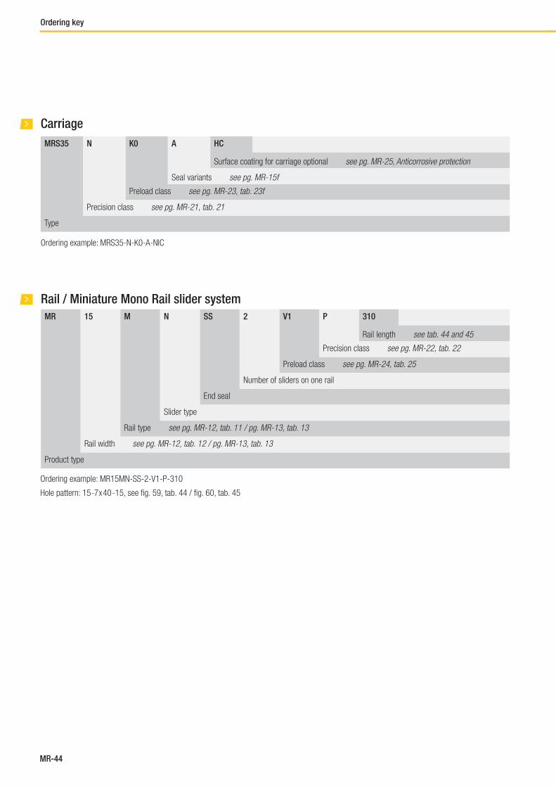
MR-44
Carriage
Ordering example: MRS35-N-K0-A-NIC
MRS35 N K0 A HC
Surface coating for carriage optional see pg. MR-25, Anticorrosive protection
Seal variants see pg. MR-15f
Preload class see pg. MR-23, tab. 23f
Precision class see pg. MR-21, tab. 21
Type
MR 15 M N SS 2 V1 P 310
Rail length see tab. 44 and 45
Precision class see pg. MR-22, tab. 22
Preload class see pg. MR-24, tab. 25
Number of sliders on one rail
End seal
Slider type
Rail type see pg. MR-12, tab. 11 / pg. MR-13, tab. 13
Rail width see pg. MR-12, tab. 12 / pg. MR-13, tab. 13
Product type
Rail / Miniature Mono Rail slider system
Ordering example: MR15MN-SS-2-V1-P-310
Hole pattern: 15 -7 x 40 -15, see fi g. 59, tab. 44 / fi g. 60, tab. 45
Ordering key
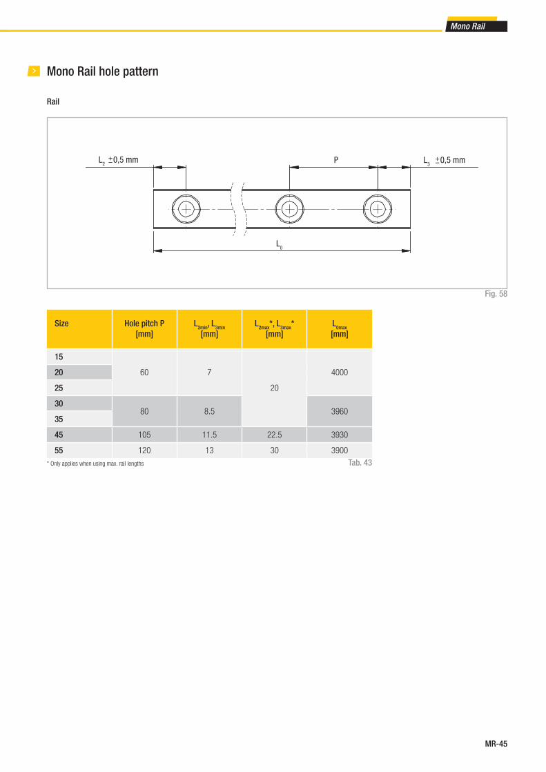
MR-45
Mono Rail
Size Hole pitch P
[mm]
L2min
, L3min
[mm]
L2max
*, L3max
*
[mm]
L0max
[mm]
15
60 7
20
400020
25
3080 8.5 3960
35
45 105 11.5 22.5 3930
55 120 13 30 3900
Fig. 58
Tab. 43
Rail
Mono Rail hole pattern
L0
L2 0,5 mm+– P L3 0,5 mm+–
* Only applies when using max. rail lengths
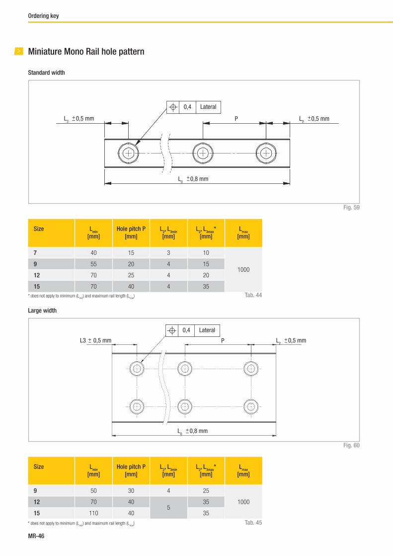
MR-46
Size Lmin
[mm]
Hole pitch P
[mm]
L2, L
3min
[mm]
L2, L
3max*
[mm]
Lmax
[mm]
7 40 15 3 10
10009 55 20 4 15
12 70 25 4 20
15 70 40 4 35
Fig. 59
Tab. 44
Standard width
Size Lmin
[mm]
Hole pitch P
[mm]
L2, L
3min
[mm]
L2, L
3max*
[mm]
Lmax
[mm]
9 50 30 4 25
100012 70 405
35
15 110 40 35
Fig. 60
Tab. 45
Large width
Miniature Mono Rail hole pattern
L3 0,5 mm+–
L0 0,8 mm+–
P L2 0,5 mm+–
0,4 Lateral
L3 0,5 mm+–
L0 0,8 mm+–
P L2 0,5 mm+–
0,4 Lateral
* does not apply to minimum (Lmin
) and maximum rail length (Lmax
)
* does not apply to minimum (Lmin
) and maximum rail length (Lmax
)
Ordering key

Curviline
FrontespizioCurviline.indd 1 07/10/2013 11:24:20
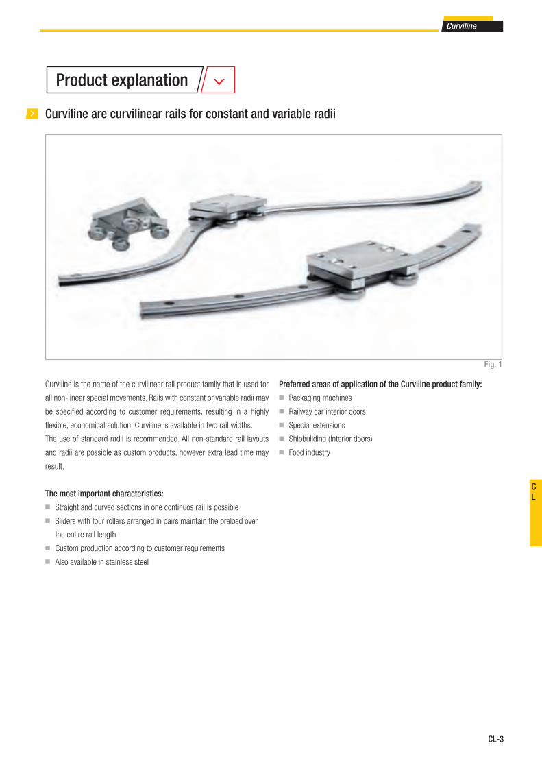
CL-3
Curviline
CL
Curviline are curvilinear rails for constant and variable radii
Curviline is the name of the curvilinear rail product family that is used for
all non-linear special movements. Rails with constant or variable radii may
be specifi ed according to customer requirements, resulting in a highly
fl exible, economical solution. Curviline is available in two rail widths.
The use of standard radii is recommended. All non-standard rail layouts
and radii are possible as custom products, however extra lead time may
result.
The most important characteristics:
■ Straight and curved sections in one continuos rail is possible
■ Sliders with four rollers arranged in pairs maintain the preload over
the entire rail length
■ Custom production according to customer requirements
■ Also available in stainless steel
Preferred areas of application of the Curviline product family:
■ Packaging machines
■ Railway car interior doors
■ Special extensions
■ Shipbuilding ( interior doors)
■ Food industry
Fig. 1
Product explanation
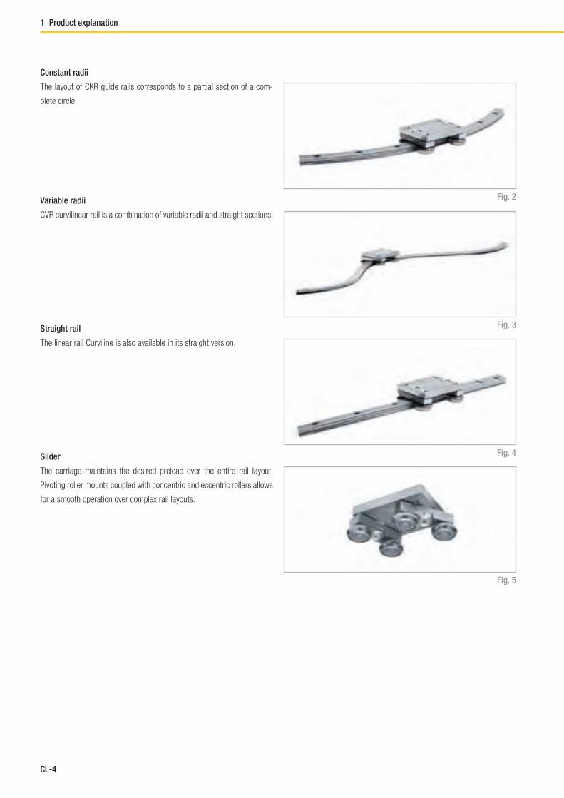
CL-4
1 Product explanation
Constant radii
The layout of CKR guide rails corresponds to a partial section of a com-
plete circle.
Variable radii
CVR curvilinear rail is a combination of variable radii and straight sections.
Fig. 2
Fig. 3Straight rail
The linear rail Curviline is also available in its straight version.
Slider
The carriage maintains the desired preload over the entire rail layout.
Pivoting roller mounts coupled with concentric and eccentric rollers allows
for a smooth operation over complex rail layouts.
Fig. 4
Fig. 5

CL-5
Curviline
CL
Performance characteristics:
■ Available rail widths: CKR01/CVR01: 16.5 mm (0.65 in)
and CKR05/CVR05: 23 mm (0.91 in)
■ Max. slider operating speed on the rail: 1.5 m/s (59 in/s)
(depending on application)
■ Max. acceleration: 2 m/s² (78 in/s²) (depending on application)
■ Max. effective length of the rail: 3,240 mm (127.56 in)
■ Max. traverse: CCT08: 3,170 mm (124.8 in)
and CCT11: 3,140 mm (123.62 in)
■ Minimum radius for steel version and not hardened version: 120 mm
■ Minimum radius for version with hardened raceways:
300 mm for section 01, 400 mm for size 05
For non-standard radii, please contact Rollon technical support.
■ Radius tolerance +/- 0.5 mm (0.02 in), angle tolerance +/- 1°
■ Temperature range: -20 °C to +80 °C (-4 °F to +176 °F)
■ Rail and runner electrolytic zinc-plated and passivated (Rollon Aloy);
increased anticorrosive protection on request
(see pg. CL-10 Anticorrosive protection)
■ Rail material: C43, AISI316L for the stainless steel version
■ Slider body material: Fe360, AISI316L for the stainless steel version
■ Radial ball bearing roller material: 100Cr6, AISI440 for the stainless
steel version
■ Rollers are lubricated for life
Remarks:
■ With a simple adjustment of the eccentric roller (denoted with a mar-
king on the bottom of the roller), the slider preload can be set to desired
preload, including clearance.
■ The recommended hole pitch is 80 mm (3.15 in) on the extended
length
■ Please indicate the precise rail layout and the desired hole pattern in a
drawing
■ Indicate if the design is a right or left version when ordering
■ Joined rails are not recommended. For more information, please
contact Rollon technical support.
■ Resulting moment loads must be absorbed through the use of two
sliders. For more information, please contact Rollon technical support.
Fig. 6
Zinc-plated rail
Bearing steel roller pins
Zinc-plated steel slider body
Technical data
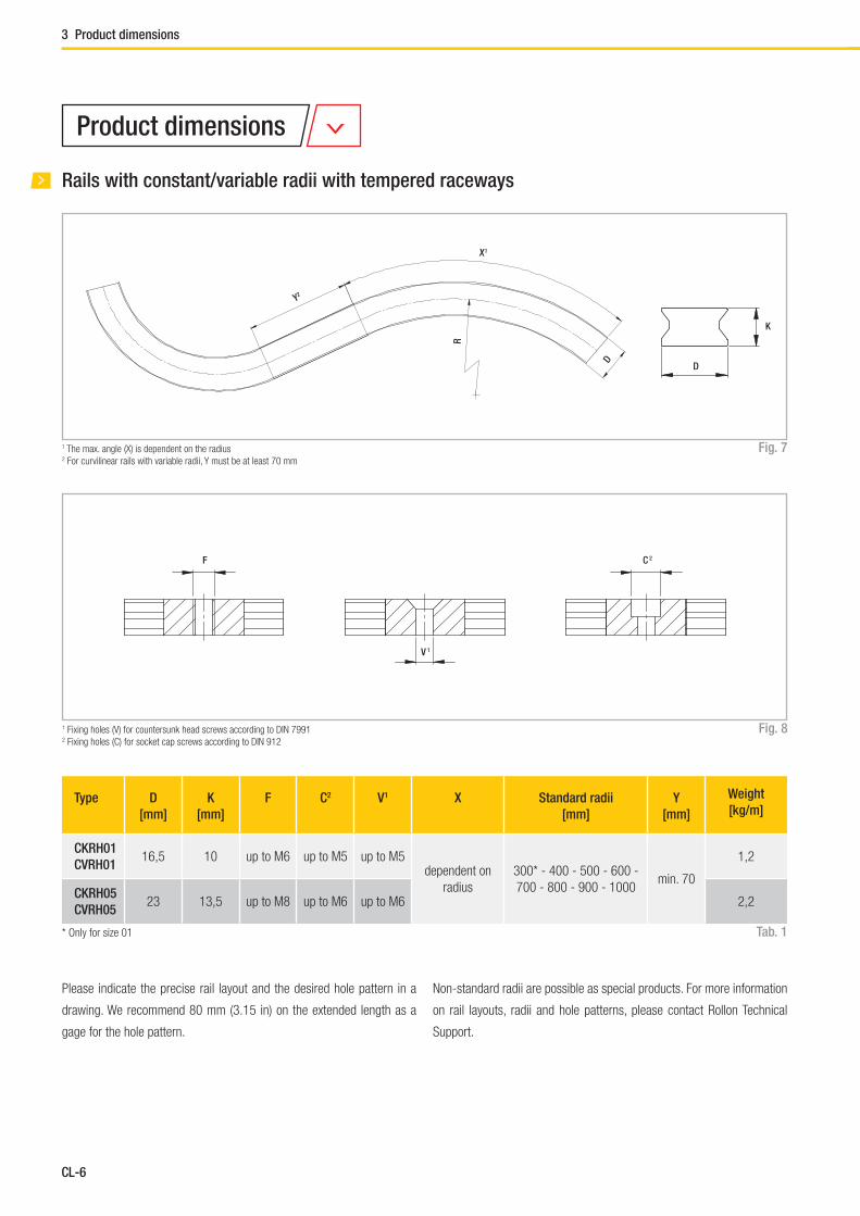
CL-6
3 Product dimensions
Fig. 81 Fixing holes (V) for countersunk head screws according to DIN 79912 Fixing holes (C) for socket cap screws according to DIN 912
F
V 1
C 2
Product dimensions
Rails with constant/variable radii with tempered raceways
Type D
[mm]
K
[mm]
F C2 V1 X Standard radii
[mm]
Y
[mm]
Weight
[kg/m]
CKRH01
CVRH0116,5 10 up to M6 up to M5 up to M5
dependent on
radius
300* - 400 - 500 - 600 -
700 - 800 - 900 - 1000min. 70
1,2
CKRH05
CVRH0523 13,5 up to M8 up to M6 up to M6 2,2
Tab. 1
Fig. 71 The max. angle (X) is dependent on the radius2 For curvilinear rails with variable radii, Y must be at least 70 mm
Please indicate the precise rail layout and the desired hole pattern in a
drawing. We recommend 80 mm (3.15 in) on the extended length as a
gage for the hole pattern.
* Only for size 01
Non-standard radii are possible as special products. For more information
on rail layouts, radii and hole patterns, please contact Rollon Technical
Support.
Y2
X1
R
D
D
K
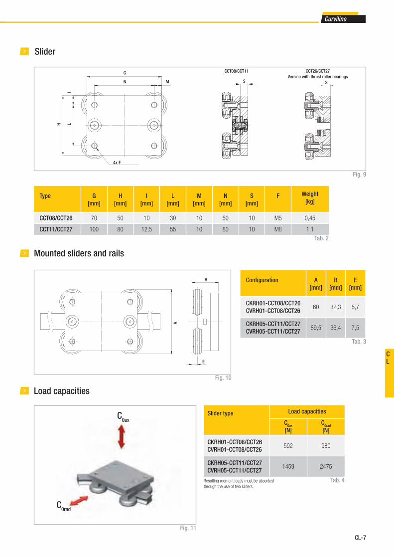
CL-7
Curviline
CL
Fig. 9
Mounted sliders and rails
Fig. 10
Tab. 2
Slider
Tab. 3
Type G
[mm]
H
[mm]
I
[mm]
L
[mm]
M
[mm]
N
[mm]
S
[mm]
F Weight
[kg]
CCT08/CCT26 70 50 10 30 10 50 10 M5 0,45
CCT11/CCT27 100 80 12,5 55 10 80 10 M8 1,1
Confi guration A
[mm]
B
[mm]
E
[mm]
CKRH01-CCT08/CCT26
CVRH01-CCT08/CCT26 60 32,3 5,7
CKRH05-CCT11/CCT27
CVRH05-CCT11/CCT2789,5 36,4 7,5
A
B
E
Load capacities
Fig. 11
Tab. 4Resulting moment loads must be absorbed
through the use of two sliders
Slider type Load capacities
C0ax
[N]
C0rad
[N]
CKRH01-CCT08/CCT26
CVRH01-CCT08/CCT26 592 980
CKRH05-CCT11/CCT27
CVRH05-CCT11/CCT271459 2475
C0rad
C0ax
S
G
MN
4x F
H LI
S S
CCT08/CCT11 CCT26/CCT27
Version with thrust roller bearings
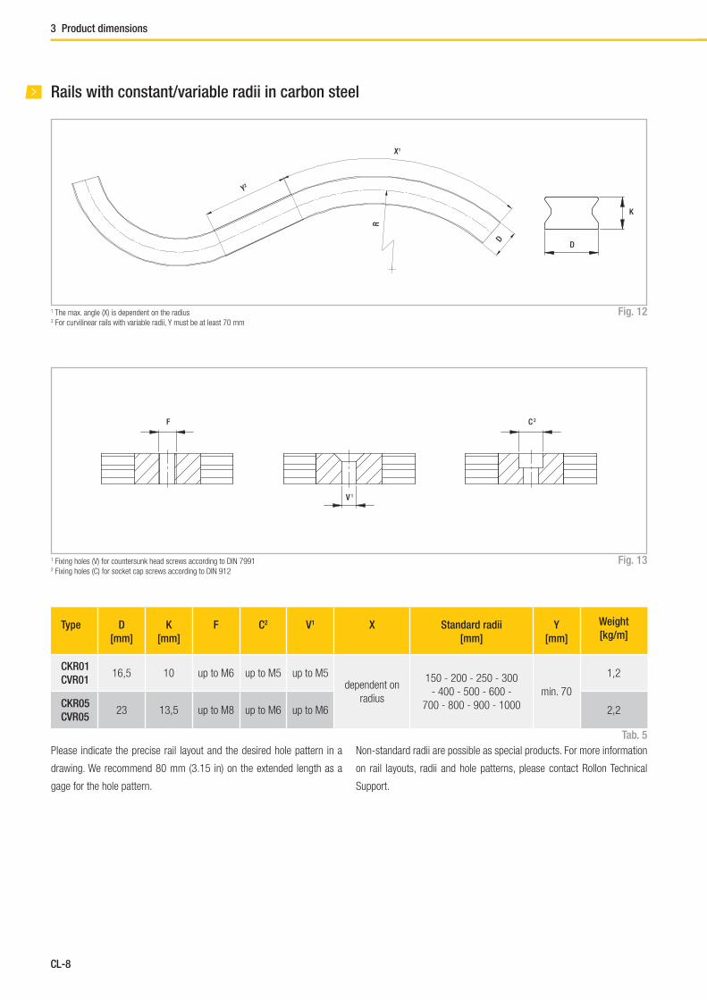
CL-8
Rails with constant/variable radii in carbon steel
Type D
[mm]
K
[mm]
F C2 V1 X Standard radii
[mm]
Y
[mm]
Weight
[kg/m]
CKR01
CVR0116,5 10 up to M6 up to M5 up to M5
dependent on
radius
150 - 200 - 250 - 300
- 400 - 500 - 600 -
700 - 800 - 900 - 1000
min. 70
1,2
CKR05
CVR0523 13,5 up to M8 up to M6 up to M6 2,2
Tab. 5
Fig. 131 Fixing holes (V) for countersunk head screws according to DIN 79912 Fixing holes (C) for socket cap screws according to DIN 912
Fig. 121 The max. angle (X) is dependent on the radius2 For curvilinear rails with variable radii, Y must be at least 70 mm
Please indicate the precise rail layout and the desired hole pattern in a
drawing. We recommend 80 mm (3.15 in) on the extended length as a
gage for the hole pattern.
Non-standard radii are possible as special products. For more information
on rail layouts, radii and hole patterns, please contact Rollon Technical
Support.
Y2
X1
R
D
D
K
F
V 1
C 2
3 Product dimensions
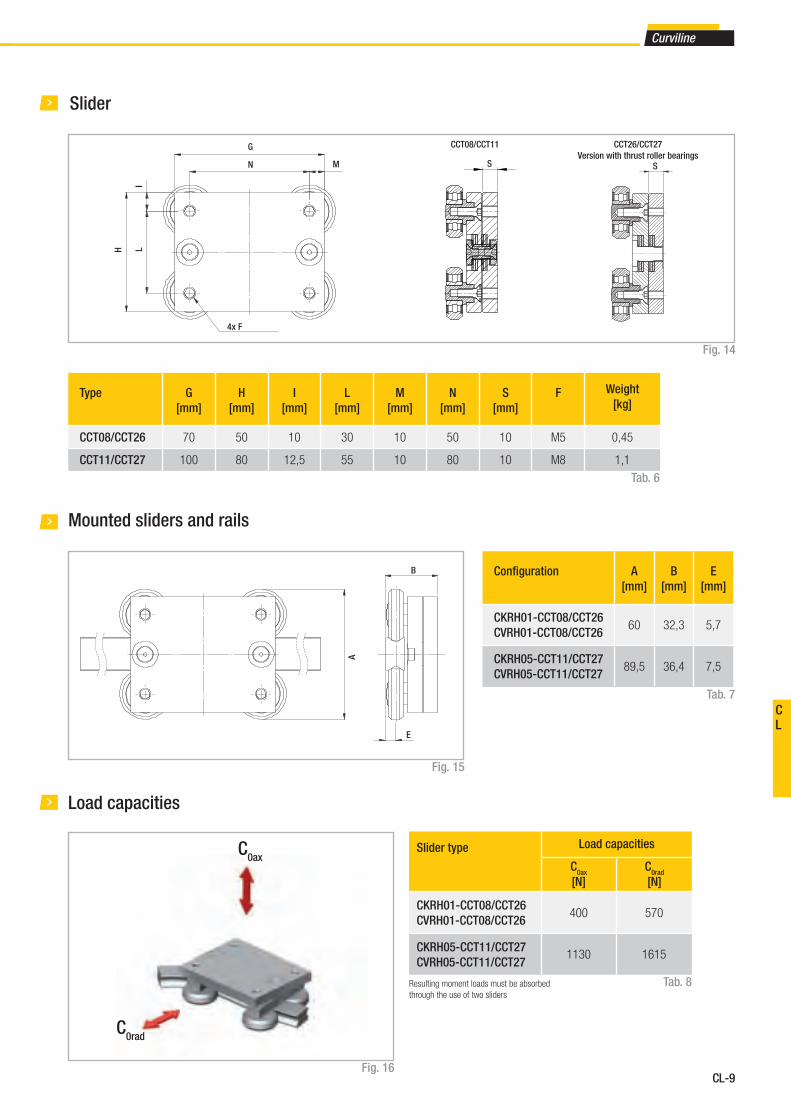
CL-9
Curviline
CL
Mounted sliders and rails
Fig. 15
Tab. 6
Slider
Fig. 14
Tab. 7
Type G
[mm]
H
[mm]
I
[mm]
L
[mm]
M
[mm]
N
[mm]
S
[mm]
F Weight
[kg]
CCT08/CCT26 70 50 10 30 10 50 10 M5 0,45
CCT11/CCT27 100 80 12,5 55 10 80 10 M8 1,1
A
B
E
Load capacities
Fig. 16
Tab. 8
C0rad
C0ax
Resulting moment loads must be absorbed
through the use of two sliders
S
G
MN
4x F
H LI
S S
Confi guration A
[mm]
B
[mm]
E
[mm]
CKRH01-CCT08/CCT26
CVRH01-CCT08/CCT26 60 32,3 5,7
CKRH05-CCT11/CCT27
CVRH05-CCT11/CCT2789,5 36,4 7,5
Slider type Load capacities
C0ax
[N]
C0rad
[N]
CKRH01-CCT08/CCT26
CVRH01-CCT08/CCT26 400 570
CKRH05-CCT11/CCT27
CVRH05-CCT11/CCT271130 1615
CCT08/CCT11 CCT26/CCT27
Version with thrust roller bearings

CL-10
Rails with constant/variable radii in stainless steel
Type D
[mm]
K
[mm]
F C2 V1 X Standard radii
[mm]
Y
[mm]
Weight
[kg/m]
CKRX01
CVRX0116,5 10 up to M6 up to M5 up to M5
dependent on
radius
150 - 200 - 250 - 300
- 400 - 500 - 600 -
700 - 800 - 900 - 1000
min. 70
1,2
CKRX05
CVRX0523 13,5 up to M8 up to M6 up to M6 2,2
Tab. 9
Fig. 181 Fixing holes (V) for countersunk head screws according to DIN 79912 Fixing holes (C) for socket cap screws according to DIN 912
Fig. 171 The max. angle (X) is dependent on the radius2 For curvilinear rails with variable radii, Y must be at least 70 mm
Please indicate the precise rail layout and the desired hole pattern in a
drawing. We recommend 80 mm (3.15 in) on the extended length as a
gage for the hole pattern.
Non-standard radii are possible as special products. For more information
on rail layouts, radii and hole patterns, please contact Rollon Technical
Support.
Y2
X1
R
D
D
K
F
V 1
C 2
3 Product dimensions
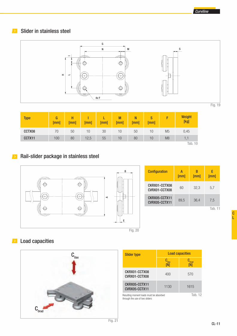
CL-11
Curviline
CL
Rail-slider package in stainless steel
Fig. 20
Tab. 10
Slider in stainless steel
Fig. 19
Tab. 11
Type G
[mm]
H
[mm]
I
[mm]
L
[mm]
M
[mm]
N
[mm]
S
[mm]
F Weight
[kg]
CCTX08 70 50 10 30 10 50 10 M5 0,45
CCTX11 100 80 12,5 55 10 80 10 M8 1,1
Confi guration A
[mm]
B
[mm]
E
[mm]
CKRX01-CCTX08
CVRX01-CCTX08 60 32,3 5,7
CKRX05-CCTX11
CVRX05-CCTX1189,5 36,4 7,5
S
G
MN
4x F
H LI
A
B
E
Load capacities
Fig. 21
Tab. 12
C0rad
C0ax
Resulting moment loads must be absorbed
through the use of two sliders
Slider type Load capacities
C0ax
[N]
C0rad
[N]
CKRX01-CCTX08
CVRX01-CCTX08 400 570
CKRX05-CCTX11
CVRX05-CCTX111130 1615

CL-12
4 Technical instructions
Lubrication
Anticorrosive protectionThe Curviline product family comes standard with electrolytic zinc plating
with passivation (RolonAloy) for anitcorrosion protection. If increased an-
ticorrosive protection is required, application-specifi c surface treatments
are available on request, e.g. as nickel-plated design with FDA approval
for use in the food industry. The Curviline series is also available in stain-
less steel. For more information, please contact Rollon technical support.
Roller lubrication
All rollers of the Curviline product family are lubricated for life.
Lubrication of the raceways
Rails must be lubricated before operation. Recommended lubrication in-
tervals are heavily dependent upon the ambient conditions, speed and
temperature. Under normal conditions, lubrication is recommended af-
ter 100 km operational performance or after an operating period of six
months. In critical application cases the interval should be shorter. Please
clean the raceways carefully before lubrication.
We recommend a roller bearing lubricant with a lithium base of average
consistency.
Different lubricants are available by request for special applications:
■ FDA-approved lubricant for use in the food industry
■ specifi c lubricant for clean rooms
■ specifi c lubricant for the marine technology sector
■ specifi c lubricant for high and low temperatures
For specifi c information, contact Rollon technical support.
Proper lubrication during normal conditions:
■ reduces friction
■ reduces wear
■ reduces the load of the contact surfaces through elastic deformations
■ reduces running noise
Technical instructions
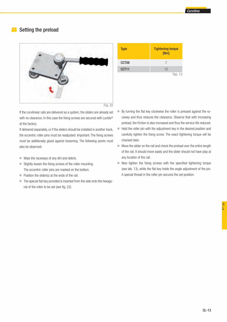
CL-13
Curviline
CL
Setting the preload
If the curvilinear rails are delivered as a system, the sliders are already set
with no clearance. In this case the fi xing screws are secured with Loctite®
at the factory.
If delivered separately, or if the sliders should be installed in another track,
the eccentric roller pins must be readjusted. Important: The fi xing screws
must be additionally glued against loosening. The following points must
also be observed:
■ Wipe the raceways of any dirt and debris.
■ Slightly loosen the fi xing screws of the roller mounting.
The eccentric roller pins are marked on the bottom.
■ Position the slider(s) at the ends of the rail.
■ The special fl at key provided is inserted from the side onto the hexago-
nal of the roller to be set (see fi g. 22).
■ By turning the fl at key clockwise the roller is pressed against the ra-
ceway and thus reduces the clearance. Observe that with increasing
preload, the friction is also increased and thus the service life reduced.
■ Hold the roller pin with the adjustment key in the desired position and
carefully tighten the fi xing screw. The exact tightening torque will be
checked later.
■ Move the slider on the rail and check the preload over the entire length
of the rail. It should move easily and the slider should not have play at
any location of the rail.
■ Now tighten the fi xing screws with the specifi ed tightening torque
(see tab. 13), while the fl at key holds the angle adjustment of the pin.
A special thread in the roller pin secures the set position.
Type Tightening torque
[Nm]
CCT08 7
CCT11 12
Fig. 22
Tab. 13
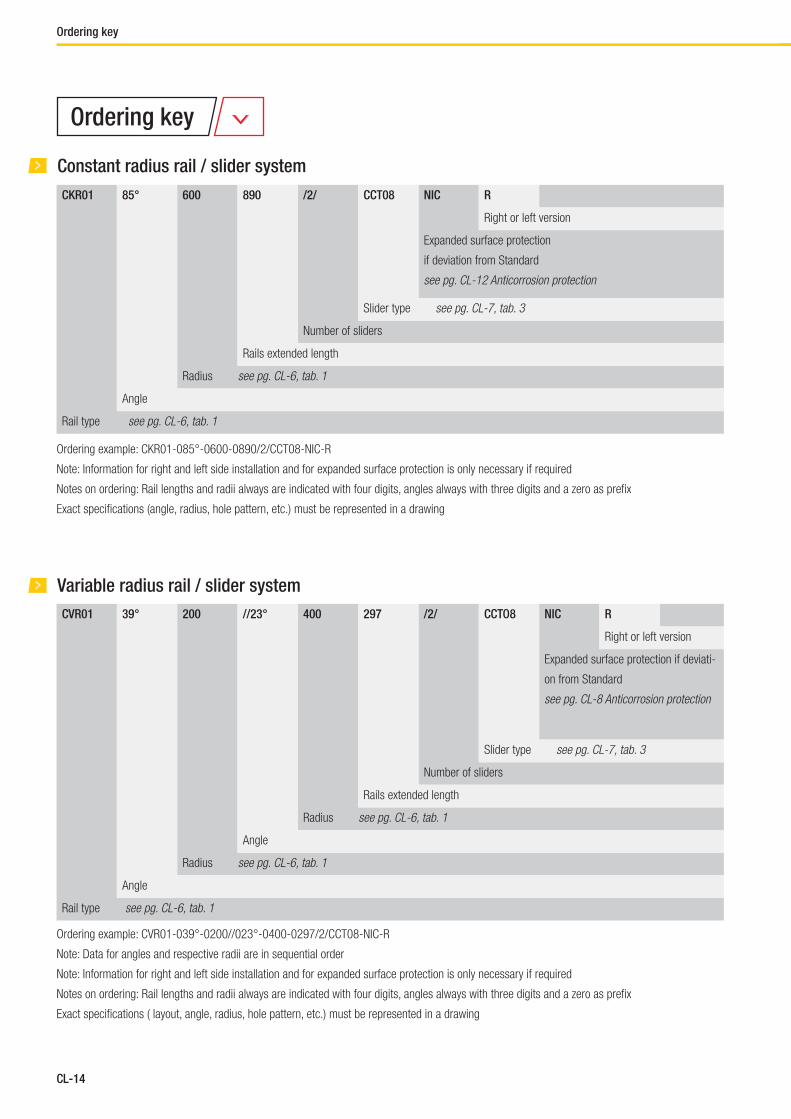
CL-14
Constant radius rail / slider system
Ordering example: CKR01-085°-0600-0890/2/CCT08-NIC-R
Note: Information for right and left side installation and for expanded surface protection is only necessary if required
Notes on ordering: Rail lengths and radii always are indicated with four digits, angles always with three digits and a zero as prefi x
Exact specifi cations (angle, radius, hole pattern, etc.) must be represented in a drawing
CKR01 85° 600 890 /2/ CCT08 NIC R
Right or left version
Expanded surface protection
if deviation from Standard
see pg. CL-12 Anticorrosion protection
Slider type see pg. CL-7, tab. 3
Number of sliders
Rails extended length
Radius see pg. CL-6, tab. 1
Angle
Rail type see pg. CL-6, tab. 1
Variable radius rail / slider system
CVR01 39° 200 //23° 400 297 /2/ CCTO8 NIC R
Right or left version
Expanded surface protection if deviati-
on from Standard
see pg. CL-8 Anticorrosion protection
Slider type see pg. CL-7, tab. 3
Number of sliders
Rails extended length
Radius see pg. CL-6, tab. 1
Angle
Radius see pg. CL-6, tab. 1
Angle
Rail type see pg. CL-6, tab. 1
Ordering example: CVR01-039°-0200//023°-0400-0297/2/CCT08-NIC-R
Note: Data for angles and respective radii are in sequential order
Note: Information for right and left side installation and for expanded surface protection is only necessary if required
Notes on ordering: Rail lengths and radii always are indicated with four digits, angles always with three digits and a zero as prefi x
Exact specifi cations ( layout, angle, radius, hole pattern, etc.) must be represented in a drawing
Ordering key
Ordering key
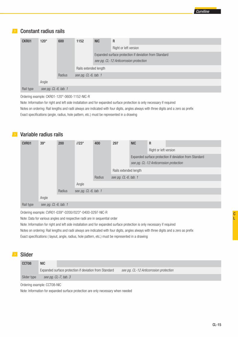
CL-15
Curviline
CL
CKR01 120° 600 1152 NIC R
Right or left version
Expanded surface protection if deviation from Standard
see pg. CL-12 Anticorrosion protection
Rails extended length
Radius see pg. CL-6, tab. 1
Angle
Rail type see pg. CL-6, tab. 1
Constant radius rails
Ordering example: CKR01-120°-0600-1152-NIC-R
Note: Information for right and left side installation and for expanded surface protection is only necessary if required
Notes on ordering: Rail lengths and radii always are indicated with four digits, angles always with three digits and a zero as prefi x
Exact specifi cations (angle, radius, hole pattern, etc.) must be represented in a drawing
Variable radius rails
CVR01 39° 200 //23° 400 297 NIC R
Right or left version
Expanded surface protection if deviation from Standard
see pg. CL-12 Anticorrosion protection
Rails extended length
Radius see pg. CL-6, tab. 1
Angle
Radius see pg. CL-6, tab. 1
Angle
Rail type see pg. CL-6, tab. 1
Ordering example: CVR01-039°-0200//023°-0400-0297-NIC-R
Note: Data for various angles and respective radii are in sequential order
Note: Information for right and left side installation and for expanded surface protection is only necessary if required
Notes on ordering: Rail lengths and radii always are indicated with four digits, angles always with three digits and a zero as prefi x
Exact specifi cations ( layout, angle, radius, hole pattern, etc.) must be represented in a drawing
Slider
CCT08 NIC
Expanded surface protection if deviation from Standard see pg. CL-12 Anticorrosion protection
Slider type see pg. CL-7, tab. 3
Ordering example: CCT08-NIC
Note: Information for expanded surface protection are only necessary when needed

Railway
Medical
Logistics
Guides suitable for all applications
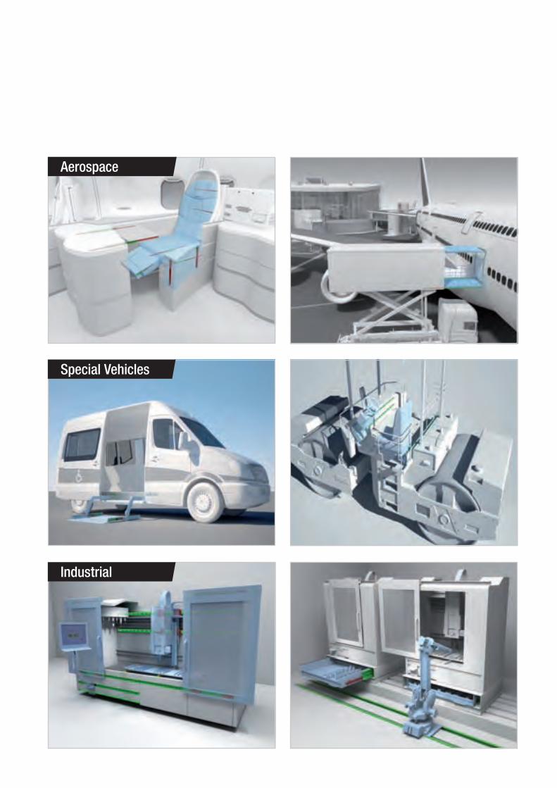
Aerospace
Special Vehicles
Industrial

Consult the other ranges of products
All addresses of our global sales partners can also be found at www.rollon.com
Changes and errors excepted. The text and images may be used only with our permission. TL_GC_EN_03/16
Rollon Branches & Rep. OfficesDistributors


