1 ME EN 7960 – Precision Machine Design – Linear Motions Systems 3-1 Linear Motion Systems ME EN 7960 – Precision Machine Design Topic 3 ME EN 7960 – Precision Machine Design – Linear Motions Systems 3-2 Major Topics • Error sources • Pneumatic and hydraulic cylinders • Belt drives • Rack and pinion drives • Friction drives • Lead screws • Linear electric motors
Transcript
1
ME EN 7960 – Precision Machine Design – Linear Motions Systems 3-1
Linear Motion Systems
ME EN 7960 – Precision Machine DesignTopic 3
ME EN 7960 – Precision Machine Design – Linear Motions Systems 3-2
Major Topics
• Error sources• Pneumatic and hydraulic cylinders• Belt drives• Rack and pinion drives• Friction drives• Lead screws• Linear electric motors
2
ME EN 7960 – Precision Machine Design – Linear Motions Systems 3-3
Error Sources
• There are five principal error sources that affect linear actuator performance:1. Form error in the device components2. Component misalignment3. Backlash4. Friction5. Thermal effects
• These systems often have long shafts (e.g. ball screws)– One must be careful of bending frequencies being excited by
rotating motors
ME EN 7960 – Precision Machine Design – Linear Motions Systems 3-4
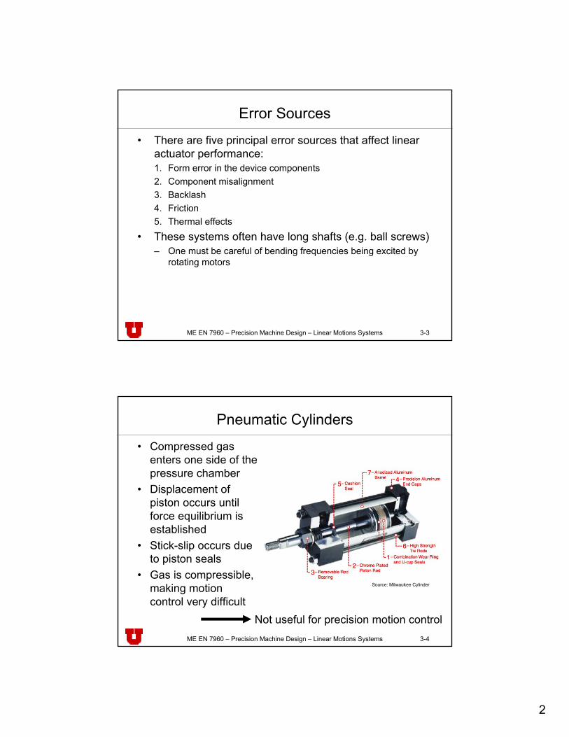
Pneumatic Cylinders
• Compressed gas enters one side of the pressure chamber
• Displacement of piston occurs until force equilibrium is established
• Stick-slip occurs due to piston seals
• Gas is compressible, making motion control very difficult
Not useful for precision motion control
Source: Milwaukee Cylinder
3
ME EN 7960 – Precision Machine Design – Linear Motions Systems 3-5
Hydraulic Cylinders
• Compressed oil enters one side of the pressure chamber
• Displacement of piston occurs until force equilibrium is established
• Stick-slip occurs due to piston seals.
• Oil is virtually incompressible, making motion control somewhat doable.
Not useful for precision motion control
ME EN 7960 – Precision Machine Design – Linear Motions Systems 3-6
Belt Drives
• To prevent the belts' edges wearing on pulley flanges:– Use side rollers to guide timing belt to prevent wear caused by
flanged sheaves:
Source: Alexander Slocum, Precision Machine Design
4
ME EN 7960 – Precision Machine Design – Linear Motions Systems 3-7
Belt Drives (contd.)
• Used in printers, semiconductor automated material handling systems, robots, etc.– Timing belts will not slip– Metal belts have greater stiffness, but stress limits life
• Timing belts will be the actuator of choice for low cost, low, stiffness, low force linear motion until:– Linear electric motor cost comes down– PC based control boards with self-tuning modular algorithms
become more prevalent
ρσ
2Et
=E Young’s modulust Belt thicknessρ Bending radius
Not useful for precision motion control
ME EN 7960 – Precision Machine Design – Linear Motions Systems 3-8
Rack and Pinion Drives
• One of the least expensive methods of generating linear motion from rotary motion– Racks can be placed end to end for as great a distance as long
as one can provide a secure base on which to bolt them
Source: Alexander Slocum, Precision Machine Design
5
ME EN 7960 – Precision Machine Design – Linear Motions Systems 3-9
Rack and Pinion Drives (contd.)
• Commonly used on very large machines such as gantry robots and machining centers used in the aircraft industry
• It is difficult to obtain the "optimal transmission ratio"– A speed reducer is sometimes used with the motor that drives
the pinion– They do not provide a mechanical advantage the way a lead
screw system does
• The characteristics of gears apply here equally well, including the use of anti-backlash or multiple pinions
ME EN 7960 – Precision Machine Design – Linear Motions Systems 3-10
Rack and Pinion Drives (contd.)
• Backlash is present in single pinion systems• For low forces, a split preloaded pinion can be used
– The internal tube acts as a torsional spring
Source: Alexander Slocum, Precision Machine Design
6
ME EN 7960 – Precision Machine Design – Linear Motions Systems 3-11
Rack and Pinion Drives (contd.)
• For high force systems, a dual pinion system can be used:– Input shaft as a beam spring to drive two rollers:
• Flexural force from beam spring causes input pinions to counter-rotate
• Input pinion and motor can be mounted on cantilever beam that acts as a spring loaded pivot arm
• Input torque causes input pinions to drive the main gear
Travel
Pinion 1
Rack
Pinion 2
Spring PreloadDrive Pinion
ME EN 7960 – Precision Machine Design – Linear Motions Systems 3-12
Friction Drives
• A wheel (capstan) driving a flat bar supported by a back up roller or hydrostatic flat pad bearing
Source: Alexander Slocum, Precision Machine Design
7
ME EN 7960 – Precision Machine Design – Linear Motions Systems 3-13
Friction Drives (contd.)
• Ideally, use hydrostatic bearings to support the drive roller shaft, and a hydrostatic flat pad bearing
• Accurate rollers are required to maintain a constant preload, transmission ratio, and constant torque
• A properly designed and manufactured friction drive can achieve nanometer resolution of motion– More common before linear electric motors were well developed– Still useful for long range of motion systems
• When a direct friction drive is properly aligned:– Only a pure radial bearing is needed to support the motor– Axial motion (walking) of the axially unrestrained shaft is an
indicator of misalignment
ME EN 7960 – Precision Machine Design – Linear Motions Systems 3-14
– Minimal backlash and dead band (due to elastic deformation)– Low drive friction– Uncomplicated design
• Their undesirable properties include:– Low drive force capability– Low to moderate stiffness and damping– Minimal transmission gain (low motor speed makes them more
susceptible to torque ripple)– High sensitivity to drive bar cleanliness– Frictional polymers can form on dry-running systems– As the capstan rolls, it compresses organic molecules in the air onto the
drive bar which builds up a layer• This layer is not uniform and causes a bumpy ride and velocity control
problems– Running the system with a tractive lubricant (e.g., Monsanto's
Santotrac™):• Increases coefficient of friction• Prevents frictional polymer buildup
8
ME EN 7960 – Precision Machine Design – Linear Motions Systems 3-15
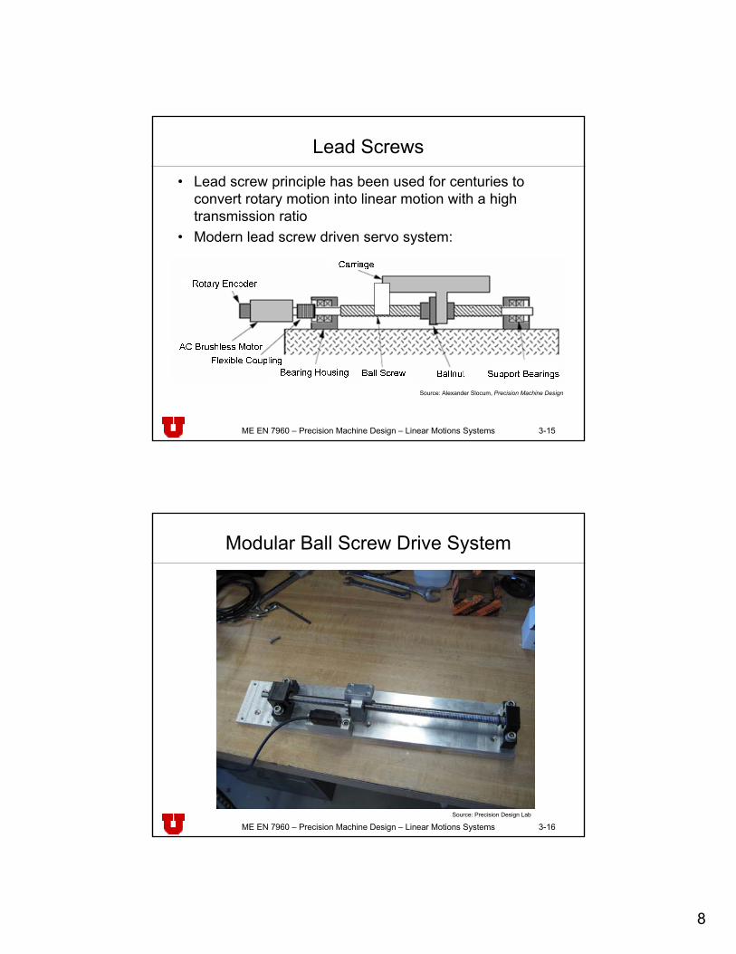
Lead Screws
• Lead screw principle has been used for centuries to convert rotary motion into linear motion with a high transmission ratio
• Modern lead screw driven servo system:
Source: Alexander Slocum, Precision Machine Design
ME EN 7960 – Precision Machine Design – Linear Motions Systems 3-16
Modular Ball Screw Drive System
Source: Precision Design Lab
9
ME EN 7960 – Precision Machine Design – Linear Motions Systems 3-17
Lead Screws (contd.)
• There are many types of lead screws that are available including:– Sliding contact thread lead screws– Traction drive lead screws– Oscillatory motion lead screws– Non-recirculating rolling element lead screws– Ball screws– Planetary roller lead screws– Wallowing thread screws– Hydrostatic lead screws
ME EN 7960 – Precision Machine Design – Linear Motions Systems 3-18
The Mechanics of Power Screws - Lifting
∑∑
=−+−=
=−−=
0sincos
0sincos
αα
αα
upy
fupx
PNFF
FFPF
NFf μ=
(1)
(2)
(3) in (2) and in (1) and solve for Pup:
( )αμααμα
sincoscossin
−+
=FPup
(3)
Source: Shigley JE, Mischke CR, Mechanical Engineering Design
Summing up forces in x and y:
The frictional force is found as:
l
(4)
10
ME EN 7960 – Precision Machine Design – Linear Motions Systems 3-19
The Mechanics of Power Screws - Lowering
∑∑
=++−=
=+−−=
0sincos
0sincos
αα
αα
downy
fdownx
PNFF
FFPF (5)
( )αμαααμ
sincossincos
+−
=FPdown
(5) in (6) and solve for Pdown:
(6)
Source: Shigley JE, Mischke CR, Mechanical Engineering Design
Summing up forces in x and y:
l(7)
ME EN 7960 – Precision Machine Design – Linear Motions Systems 3-20
Lead Screws – Torque Calculations
pdl
πα =tan
p
pup
dl
dlF
P
πμ
μπ
−
⎟⎟⎠
⎞⎜⎜⎝
⎛+
=1
p
pdown
dldlF
P
πμπ
μ
+
⎟⎟⎠
⎞⎜⎜⎝
⎛−
=1
Using: (8)
(8) in (4): (8) in (7):
(11)2
pFdT =
(9) (10)
The torque T applied can be written as the product of force F and pitch diameter dp
⎟⎟⎠
⎞⎜⎜⎝
⎛
−
+=
lddlFd
Tp
ppup μπ
πμ2 ⎟
⎟⎠
⎞⎜⎜⎝
⎛
+
−=
ldldFd
Tp
ppdown μπ
πμ2
(11) in (9): (11) in (10):
(12) (13)
Source: Shigley JE, Mischke CR, Mechanical Engineering Design
11
ME EN 7960 – Precision Machine Design – Linear Motions Systems 3-21
Lead Screws – Torque Calculations (contd.)
⎟⎟⎠
⎞⎜⎜⎝
⎛
−
+=
lddlFd
Tp
ppup μθπ
πμθcos
cos2
For the case of an Acme screw, the wedging effect of the thread angle needs to be considered. This is done by dividing the frictional terms in Eq. (12) and (13) by cosθ.
⎟⎟⎠
⎞⎜⎜⎝
⎛
+
−=
ldldFd
Tp
ppdown μθπ
θπμcos
cos2
Source: Shigley JE, Mischke CR, Mechanical Engineering Design
(14) (15)
ME EN 7960 – Precision Machine Design – Linear Motions Systems 3-22
Self Locking
θπμ cosld p >
Screws are said to be self-locking if the friction inside the nut is large enough to create a positive torque. Self-locking resists spinning of the nut when an external force F is applied to the threaded shaft.
Thus the condition for self-locking is:
(19)
12
ME EN 7960 – Precision Machine Design – Linear Motions Systems 3-23
Lead Screws (contd.)• The efficiency η is:
0 10 20 30 40 50 60 70 80 900
10
20
30
40
50
60
70
80
90
100
Lead Angle (deg)
= 0.01
= 0.02
= 0.05
= 0.15 = 0.10
Thread Angle = 0
= 0.20αμθαμθη
cotcostancos
+−
=
αμαμη
cot1tan1
+−
=
For square thread:
(18)
(17)
Source: Juvinall RC, Marshek KM, Fundamentals of Machine Component Design
ME EN 7960 – Precision Machine Design – Linear Motions Systems 3-24
Stresses in Lead Screws
• The force that is generated creates tensile and torsionalshear stresses
• The thread root is a stress concentration area (a factor of 2-3), which is somewhat mitigated when the threads are rolled (as opposed to cut)
• Assuming a thread root diameter rtr , the stresses are:
2tr
tensiletensile r
Fπ
σ =3
2
trshear r
Tπ
τ =
The equivalent (Von Mises) stress:
22 3 sheartensileequivalent τσσ +=
13
ME EN 7960 – Precision Machine Design – Linear Motions Systems 3-25
Sliding Contact Lead Screws
• Molded plastic nuts are often split and preloaded by an O-ring which puts circumferential pressure on the nut
• Commercially available thread ground and lapped sliding contact thread lead screw assemblies may have nuts preloaded against each other
• They may have split nuts that are preloaded with a circumferential spring
Source: Alexander Slocum, Precision Machine Design
ME EN 7960 – Precision Machine Design – Linear Motions Systems 3-26
Sliding Contact Lead Screws (contd.)
• Range from least expensive (machine finished) to most expensive (lapped) lead screws.
• Usually the nut is made of a bearing brass or bronze but can also be made from PTFE or the nut can be replicated.
• For low force applications, the nut can be bored without threads and then have axial slits cut into it.– The nut is then placed over a fine pitch lead screw (e.g. 100
threads per inch).– O-rings circumferentially clamp the nut and the screw will then
make its own impressions into the nut.
14
ME EN 7960 – Precision Machine Design – Linear Motions Systems 3-27
Sliding Contact Lead Screws (contd.)
• The coefficient of friction between a sliding thread contact lead screw can range from:– 0.1 for a greased nut– 0.05 for a lightly loaded lapped thread
• Load capacity is an order of magnitude less than for a ball screw
• However, the lapped continuous contact thread provides much greater smoothness of motion
• Allows a ground and lapped screw to achieve sub-micro-inch motion once initial stick slip has been overcome
• Sliding contact threads can also be replicated in-place, and sometimes can even be used to make a hybrid screw
ME EN 7960 – Precision Machine Design – Linear Motions Systems 3-28
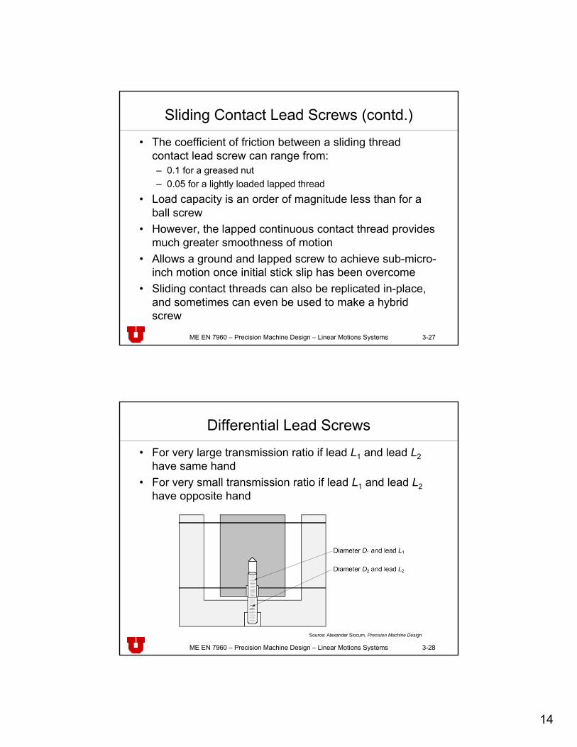
Differential Lead Screws
• For very large transmission ratio if lead L1 and lead L2have same hand
• For very small transmission ratio if lead L1 and lead L2have opposite hand
Source: Alexander Slocum, Precision Machine Design
15
ME EN 7960 – Precision Machine Design – Linear Motions Systems 3-29
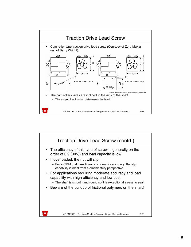
Traction Drive Lead Screw• Cam roller-type traction drive lead screw (Courtesy of Zero-Max a
unit of Barry Wright):
• The cam rollers' axes are inclined to the axis of the shaft– The angle of inclination determines the lead
Source: Alexander Slocum, Precision Machine Design
ME EN 7960 – Precision Machine Design – Linear Motions Systems 3-30
Traction Drive Lead Screw (contd.)
• The efficiency of this type of screw is generally on the order of 0.9 (90%) and load capacity is low
• If overloaded, the nut will slip– For a CMM that uses linear encoders for accuracy, the slip
capability is ideal from a crash/safety perspective
• For applications requiring moderate accuracy and load capability with high efficiency and low cost– The shaft is smooth and round so it is exceptionally easy to seal
• Beware of the buildup of frictional polymers on the shaft!
16
ME EN 7960 – Precision Machine Design – Linear Motions Systems 3-31
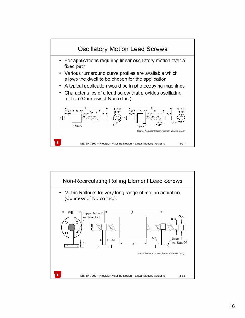
Oscillatory Motion Lead Screws
• For applications requiring linear oscillatory motion over a fixed path
• Various turnaround curve profiles are available which allows the dwell to be chosen for the application
• A typical application would be in photocopying machines• Characteristics of a lead screw that provides oscillating
motion (Courtesy of Norco Inc.):
Source: Alexander Slocum, Precision Machine Design
ME EN 7960 – Precision Machine Design – Linear Motions Systems 3-32
Non-Recirculating Rolling Element Lead Screws
• Metric Rollnuts for very long range of motion actuation (Courtesy of Norco Inc.):
Source: Alexander Slocum, Precision Machine Design
17
ME EN 7960 – Precision Machine Design – Linear Motions Systems 3-33
Non-Recirculating Rolling Element Lead Screws (contd.)
• Primary feature of the Rollnut is the rolling elements are fixed and can pass over discontinuities in the shaft
• A very long shaft can be spliced together and suspended by shaft hangers
• The non-rotating nut can travel tens of meters without worry of shaft deflection and critical speeds except for regions between hangers
• Very useful in material handling systems
ME EN 7960 – Precision Machine Design – Linear Motions Systems 3-34
Ball Screws• There are two main types of ball screw nuts (Courtesy of NSK
Corp.):
• The tube-type uses a pick-up finger to gather the balls as they exit the nut's thread helix and a tube to direct them back to the beginning of the thread helix.– Large lead/diameter ratios are possible (2:1)– The speed of the shaft (rpm) x shaft diameter (mm) is limited to about
90,000Source: Alexander Slocum, Precision Machine Design
18
ME EN 7960 – Precision Machine Design – Linear Motions Systems 3-35
Ball Screws (contd.)
• Ball screws are perhaps the most common type used in industrial machinery and precision machines
• Ball screws can be used to easily achieve repeatability on the order of one micron
• Specially manufactured and tested ball screws can attain submicron motion resolution
• Very high efficiency is obtained by using rolling steel balls to transfer loads from the screw shaft to the nut threads– Smaller spacer balls in-between load-carrying balls increases
the allowable speed and the smoothness of operation (greater resolution)
– The use of spacer balls halves the number of load carrying balls, so load capacity is cut by roughly 50%
ME EN 7960 – Precision Machine Design – Linear Motions Systems 3-36
Preloading Methods
• Preloading removes backlash in ball screw nuts• There are four basic ways:
– Tensile preloading is created by inserting an oversize spacer between two nuts and then clamping the nuts together
– Compressive preloading uses an undersize spacer between two nuts that are clamped together
– P-type preloading uses oversize balls, and a single nut to reduce cost
– Z-type preloading is also obtained with a single nut by shifting the lead between ball circuits
• Preloading reduces the load capacity, increases the nut stiffness, and increases internal friction (heat!!!)
19
ME EN 7960 – Precision Machine Design – Linear Motions Systems 3-37
Tensile Preloading
• Tensile preloading is created by inserting an oversize spacer between two nuts and then clamping the nuts together:– One nut takes loads in one
direction and the other takes loads in the other direction
– This creates a back-to-back mounting effect that is thermally stable for a rotating shaft design
– Just like for rotary ball bearings, a back-to-back nut is more sensitive to misalignment errors Source: THK Co., Ltd.
ME EN 7960 – Precision Machine Design – Linear Motions Systems 3-38
Tensile Preloading – Thermal Stability
Scenario: Temperature of the shaft is greater than that of the nut. Because the contact pressure remains largely unchanged despite the thermal expansion of the shaft, the system is called thermally stable.
20
ME EN 7960 – Precision Machine Design – Linear Motions Systems 3-39
Compressive Preloading
• Compressive preloading uses an undersize spacer between two nuts.– This creates a face-to-face mounting situation:
• Thermally stable if the nut is likely to be hotter than the lead screw– If the nut has an angular displacement imposed on it due to
mounting errors:• The ball loads will be lower and life will be longer than with a back-
to-back preloadSource: Alexander Slocum, Precision Machine Design
ME EN 7960 – Precision Machine Design – Linear Motions Systems 3-40
Compressive Preloading – Thermal Stability
Scenario: Temperature of the nut is greater than that of the shaft. Because the contact pressure remains largely unchanged despite the thermal expansion of the nut, the system is called thermally stable.
21
ME EN 7960 – Precision Machine Design – Linear Motions Systems 3-41
balls, and a single nut to reduce cost• Preload is obtained by four point
contact between the balls and the Gothic arch thread shape of the shaft and the nut– This greatly increases the amount of
skidding (differential spin) the ball is subjected to
– Because of skidding, this type of preload should not be used for precision systems
• If an axis is primarily loaded in one direction (gravity), the P-type preloading is effective and economical
Source: THK Co., Ltd.
ME EN 7960 – Precision Machine Design – Linear Motions Systems 3-42
P-Type Preloading (contd.)
• A circular arch groove typically has 3% slip during rolling compared to 40% for a Gothic arch groove:
• As sensitive to misalignment as is tensile preloadingSource: Alexander Slocum, Precision Machine Design
22
ME EN 7960 – Precision Machine Design – Linear Motions Systems 3-43
Z-Type Preloading• Z-type preloading is also
obtained with a single nut by shifting the lead between ball circuits– This creates two point contact
between the balls and the grooves
– Tensile or compressive mode– Two types:
• Two circuits with spaced lead• Single circuit with the circuit
having a midway transition point or "skip" by the preload amount
– No differential spin occurs, hence high degree of accuracy for an extended period of time
Source: THK Co., Ltd.
ME EN 7960 – Precision Machine Design – Linear Motions Systems 3-44
Spring Type Preload
• Simple preload method• Thermally stable• Useful if stiffness is not required
Source: THK Co., Ltd.
23
ME EN 7960 – Precision Machine Design – Linear Motions Systems 3-45
Roller Screws
• Use rollers instead of balls to convert rotary to linear motion and transfer forces between the nut and the shaft
• Rollers have a single thread with a pitch equal to the lead screw's apparent pitch (real pitch / number of leads)
• The rollers mesh with both the screw and the nut
Source: Alexander Slocum, Precision Machine Design
ME EN 7960 – Precision Machine Design – Linear Motions Systems 3-46
Recirculating Roller Screws
• The nut has a region that allows the rollers to move radially out of the shaft thread
• A cam sends the rollers back to start a new circuit• Allows for very fine pitch threads (2 mm)
24
ME EN 7960 – Precision Machine Design – Linear Motions Systems 3-47
Some Facts about Roller Screws• Roller screw size ranges:
– Diameter ranging from 3.5 to 200 mm– Pitch ranging from 1 to 40 mm– Single nut dynamic load capacity ranging from 5300 N to 753 kN
• The nut can be made in one piece without preload, or in two pieces if preload is required
• Maximum speed of a planetary roller lead screw is ω(rpm) x D (mm) = 140,000 (twice that of a ball screw)
• The large number of contacting threads creates a large averaging effect
• This also gives roller screws load and stiffness capabilities many times higher than similar diameter ball screws
ME EN 7960 – Precision Machine Design – Linear Motions Systems 3-48
Some Facts about Roller Screws (contd.)
• Depending on the screw, a roller screw may cost one to three times as much as a ball screw– Hertz contact area is 3x that of a same size ball screw– Load capacity is 3x that of a same size ball screw– Life = (F/Fmax)3, so life is 27x that of a same size ball screw
• Roller screws are manufactured with accuracies and efficiencies equal to those of ball screws– CAREFUL: Tens-of-hours run-in may be required to ensure the
very stiff nuts are properly preloaded!
• Planetary roller screws are much more quiet than ball screws