1 REV 0 - A - 2004301050 L-H2-056 WARNING: For Outdoor Use Only. Installation and service must be performed by an NFI certified or other qualified installer, service agency, or the gas supplier. Robert H. Peterson Co. • 14724 East Proctor Avenue • City of Industry, CA 91746 Robert H. Peterson Co. • 14724 East Proctor Avenue • City of Industry, CA 91746 Robert H. Peterson Co. • 14724 East Proctor Avenue • City of Industry, CA 91746 INSTALLATION & OWNER’S MANUAL WARNING Improper installation, adjustment, alteration, service, or maintenance can cause property damage, personal injury, or loss of life. Read the installation, operating and maintenance instructions thoroughly before installing or servicing this equipment. CODE AND SUPPLY REQUIREMENTS: The installation must conform with local codes and ordinances, or, in the absence of local codes, with the latest National Fuel Gas Code, ANSI Z223.1. This appliance is designed as an attended appliance. Adults must be present when the unit is operating. DO NOT leave this unit burning when unattended. If this product is left burning unattended, it may cause damage or serious injury. Important: Read these instructions carefully before starting installation of the unit. IMPORTANT For safe operation and proper performance of this product and to comply with certification, listings, and building code acceptances, use ONLY Peterson AFD controls, parts, decorative media, and accessories that have been specifically listed or certified for use with this burner system. Use of other controls, parts, or accessories is prohibited and will void all warranties, certifications, listings, and building code approvals, and may cause property damage, personal injury, and loss of life. Certified to: ANSI Z21.97/CSA 2.41 for outdoor decorative gas appliances LINEAR OUTDOOR FIRE PIT COMPONENTS Series: OCBP-48(P) OCBP model shown (Media purchased separately) INSTALLER: Leave this manual with the appliance. CONSUMER: Retain this manual for future reference. DANGER CARBON MONOXIDE HAZARD This appliance can produce carbon monoxide which has no odor. Using it in an enclosed space can kill you. Never use this appliance in an enclosed space such as a camper, tent, car, or home. DANGER FIRE OR EXPLOSION HAZARD If you smell gas: • Shut off gas to the appliance. • Extinguish any open flame. • If odor continues, leave the area immediately. • After leaving the area, call your gas supplier or fire department. Failure to follow these instructions coud result in fire or explosion, which could cause property damage, personal injury, or death. WARNING Do not store or use gasoline, or other flammable vapors and liquids, in the vicinity of this or any other appliance. A LP- cylinder not connected for use shall not be stored in the vicinity of this or any other appliance. WARNING: If the information in this manual is not followed exactly, a fire or explosion may result causing property damage, personal injury, or loss of life.
Transcript
1REV 0 - A - 2004301050 L-H2-056
WARNING: For Outdoor Use Only.Installation and service must be performed by an NFI certified or other qualified installer, service agency, or the gas supplier.
Robert H. Peterson Co. • 14724 East Proctor Avenue • City of Industry, CA 91746 Robert H. Peterson Co. • 14724 East Proctor Avenue • City of Industry, CA 91746 Robert H. Peterson Co. • 14724 East Proctor Avenue • City of Industry, CA 91746
INSTALLATION & OWNER’S MANUAL
WARNINGImproper installation, adjustment, alteration, service, or maintenance can cause property damage, personal injury, or loss of life. Read the installation, operating and maintenance instructions thoroughly before installing or servicing this equipment.
CODE AND SUPPLY REQUIREMENTS:The installation must conform with local codes and ordinances, or, in the absence of local codes, with the latest National Fuel Gas Code, ANSI Z223.1.
This appliance is designed as an attended appliance. Adults must be present when the unit is operating. DO NOT leave this unit burning when unattended. If this product is left burning unattended, it may cause damage or serious injury.
Important: Read these instructions carefully before starting installation of the unit.
IMPORTANTFor safe operation and proper performance of this product and to comply with certification, listings, and building code acceptances, use ONLY Peterson AFD controls, parts, decorative media, and accessories that have been specifically listed or certified for use with this burner system. Use of other controls, parts, or accessories is prohibited and will void all warranties, certifications, listings, and building code approvals, and may cause property damage, personal injury, and loss of life.
Certified to: ANSI Z21.97/CSA 2.41 for outdoor decorative
gas appliances
LINEAR OUTDOOR FIRE PIT COMPONENTS
Series:OCBP-48(P)
OCBP model shown
(Media purchased separately)
INSTALLER: Leave this manual with the appliance.CONSUMER: Retain this manual for future reference.
DANGER CARBON MONOXIDE HAZARD
This appliance can produce carbon monoxide which has no odor. Using it in an enclosed space can kill you. Never use this appliance in an enclosed space such as a camper, tent, car, or home.
DANGERFIRE OR EXPLOSION HAZARDIf you smell gas:
• Shut off gas to the appliance.• Extinguish any open flame.• If odor continues, leave the area immediately.• After leaving the area, call your gas supplier
or fire department.Failure to follow these instructions coud result in fire or explosion, which could cause property damage, personal injury, or death.
WARNINGDo not store or use gasoline, or other flammable vapors and liquids, in the vicinity of this or any other appliance.A LP- cylinder not connected for use shall not be stored in the vicinity of this or any other appliance.
WARNING: If the information in this manual is not followed exactly, a fire or explosion may result causing property damage, personal injury, or loss of life.
2REV 0 - A - 2004301050 L-H2-056
AVERTISSEMENTL'installation, l'ajustement, le changement, le service, ou l'entretien inexact peuvent causer des dégats matériels, le dommage corporel, ou des pertes humaines. Lisez l'installation, l'opération et les instructions d'entretien complètement avant d'installer ou entretenir cet équipement.
CONDITIONS DE CODE ET D'APPROVISIONNEMENT:L'installation doit se conformer aux codes locaux et aux ordonnances, ou, en l'absence des codes locaux, au plus défunt code national de gaz de carburant, la norme ANSI Z223.1.
Cet appareil est conçu comme appareil occupé. Les adultes doivent être présent quand l'unité fonctionne. Ne laissez pas ce burning d'unité si sans surveillance. Si ce produit est laissé sans surveillance brûlant, il peut causer des dommages ou des dommages sérieux.
Important: Lisez ces instructions soigneusement avant de commencer l'installation de l'unité.
IMPORTANTPour un fonctionnement en toute sécurité et le bon fonctionnement de ce produit et pour se conformer aux certifications, listes et acceptations des codes du bâtiment, utilisez UNIQUEMENT les commandes, pièces, supports décoratifs et accessoires Peterson AFD spécialement répertoriés ou certifiés pour être utilisés avec ce système de brûleur. L'utilisation d'autres commandes, pièces, ou accessoires est interdite et videra toutes les garanties, certifications, listes, et approbations de codes du bâtiment, et peut causer des dégats matériels, le dommage corporel, et des pertes humaines.
Certifié à: ANSI Z21.97/CSA 2.41
pour les appareils à gaz décoratifs extérieurs
INSTALLATION ET MODE D'EMPLOI
Series:OCBP-48(P)
Modèle OCBP illustré
LINÉAIRE COMPOSANTS PIT DE FEU EN PLEIN AIR
(Médias achetés séparément)
AVERTISSEMENT: pour usage extérieur uniquement.L'installation et l'entretien doivent être effectués par un installateur certifié NFI ou par un autre installateur qualifié, une agence de service ou le fournisseur de gaz.
DANGERRISQUE DE MONOXYDE DE CARBONECet appareil peut produire du monoxyde de carbone qui n'a pas d'odeur.L'utiliser dans un espace clos peut vous tuer.N'utilisez jamais cet appareil dans un espace clos tel qu'un camping-car, une tente, une voiture ou une maison.
DANGERRISQUE D'INCENDIE OU D'EXPLOSIONSi vous sentez du gaz:
• Coupez le gaz à l'appareil.• Éteignez toute flamme nue.• Si l'odeur persiste, quittez immédiatement
la zone.• Après avoir quitté la zone, appelez votre
fournisseur de gaz ou le service d'incendie.Le non-respect de ces instructions peut entraîner un incendie ou une explosion, ce qui pourrait provoquer des dommages matériels, des blessures corporelles ou la mort.
AVERTISSEMENTNe pas stocker ni utiliser d'essence ou d'autres vapeurs et liquides inflammables à proximité de cet appareil ou de tout autre appareil.Une bouteille LP non connectée pour utilisation ne doit pas être stockée à proximité de cet appareil ou de tout autre appareil.
AVERTISSEMENT: si les informations contenues dans ce manuel ne sont pas suivies à la lettre, un incendie ou une explosion peut en résulter, causant des dommages matériels, des blessures corporelles ou la mort.
INSTALLATEUR: Laissez ce manuel avec l'appareil.CONSOMMATEUR: Conservez ce manuel pour référence future.
3REV 0 - A - 2004301050 L-H2-056
DANGER: FLAMMABLE GAS UNDER PRESSURE. LEAKING LP-GAS MAY CAUSE A FIRE OR EXPLOSION IF IGNITED
CAUSING SERIOUS BODILY INJURY OR DEATH.CONTACT LP GAS SUPPLIER FOR REPAIRS, OR DISPOSAL OF THIS
CYLINDER OR UNUSED LP-GAS.
WARNING: FOR OUTDOOR USE ONLY.* DO NOT USE OR STORE CYLINDER IN A BUILDING,
GARAGE OR ENCLOSED AREA.
WARNING:• Know the odor of LP-gas. If you hear, see
or smell leaking LP-gas, immediately get everyone away from the cylinder and call the Fire Department. Do not attempt repairs.
• Caution your LP-gas supplier to:
Be certain cylinder is purged of trapped air prior to first filling.
Be certain not to over fill the cylinder. Be certain cylinder requalification date
is checked.• LP-gas is heavier than air and may settle in low
places while dissipating.
• Contact with the liquid contents of cylinder will cause freeze burns to the skin.
• Do not allow children to tamper or play with cylinder.
• When not connected for use, keep cylinder valve turned off. Self contained appliances shall be limited to a cylinder of 20 lb capacity or less.
• Do not use, store or transport cylinder where it would be exposed to high temperatures. Relief valve may open allowing a large amount of flammable gas to escape.
• When transporting, keep cylinder secured in an upright position with cylinder valve turned off.
WHEN CONNECTING FOR USE:• Use only in compliance with applicable
concerning the cylinder connection provided with your appliance.
• Be sure regulator vent is not pointing up. • Turn off all valves on the appliance.• Do not check for gas leaks with a match
or open flame. Apply soapy water at areas marked “X”. Open cylinder valve. If bubble appears, close valve and have LP-gas service person make needed repairs. Also, check appliance valves and connections to make sure they do not leak before lighting appliance.
• Light appliance(s) following manufacturer’s instructions.
• When appliance is not in use, keep the cylinder valve closed.
DO NOT REMOVE, DEFACE, OR OBLITERATE THE LABEL ON THE CYLINDER* EXCEPT AS AUTHORIZED BY ANSI/NFPA 58.
DANGER. Do not store a spare LP cylinder under or near this or any appliance or other heat sources.NEVER fill an LP cylinder beyond 80% full: a fire causing death or serious injury may occur.
IN ADDITION TO THIS PAGE, FOLLOW ALL INFORMATION IN THIS MANUAL REGARDING PROPANE CYLINDERS.
Cylinder valve hand wheel
Point of connection
Liquid level indicator (optional)
Cylinder
Pressure relief valve
UL
X
X XX
PROPANE GAS CYLINDER WARNING (IF APPLICABLE)
4REV 0 - A - 2004301050 L-H2-056
DANGER: Gaz inflammable sous pression.Une fuite de GPL peut causer un incendie ou une explosion sienflammée entraînant des blessures corporelles
graves ou la mort.Communiquer avec le fournisseur de GPL pour les réparations oupour disposer de cette bouteille ou du GPL non utilisé.
AVERTISSEMENT: Pour usage à l’extérieur seulement.*Ne pas utiliser ni entreposer la bouteille dans un bâtiment, un garageou un endroit fermé.
AVERTISSEMENT:• Apprenez à reconnaître l’odeur du GPL. Si
vous entendez, voyez ou sentez une fuite de GPL,éloignez immédiatement toutes les personnes dela bouteille et appelez le service d’incendie. Netentez aucune réparation.
• Avertissement pour le fournisseur de GPL: Assurez-vous que la bouteille a été purgée de tout l’air avant de procéder au remplis-sage initial.Assurez-vous de ne pas trop remplir la bouteille. Assurez-vous que la date de requalification de labouteille a été vérifiée.
• Le GPL est plus lourd que l’air et peut se déposer près du sol avant de se dissiper
• Le contact avec le contenu liquide de la bouteillepeut causer des brûlures à la peau par le froid.
• Ne pas permettre aux enfants de jouer avec la bouteille.
• Si la bouteille n’est pas raccordée pour utilisation, s’assurer que le robinet est fermé.Les bouteilles des appareils autonomes decuisson en plein air doivent être limitées àune capacité d’au plus 20 lb.
• Ne pas utiliser, entreposer ni transporter une bouteille si elle risque d’être exposée à des températures élevées. La soupape de décharge pourrait s’ouvrir et libérer une grande quantité de gaz inflammable.
• Lors du transport, sécuriser la bouteille enposition debout et s’assurer que le robinet estfermé.
Lors du raccordement pour utilisation :• Utilisez uniquement conformément aux codes
en vigueur.• Lisez et suivez les instructions du fabricant• Consultez les instructions du fabricant visant
le raccordement de la bouteille fournie avec l’appareil.
• Assurez-vous que l’évent du régulateur n’est pas dirigé vers le haut.
• Fermez tous les robinets sur l’appareil.• Ne pas utiliser d’allumette ou de flamme nue
pour vérifier la présence d’une fuite de gaz. Appliquez une solution d’eau savonneuse sur les zones marquées d’un « X ». Ouvrir le robinet de la bouteille. Si des bulles se forment, fermez le robinet et demandez à une personne qualifiée pour l’entretien d’appareils au GPL de faire les réparations requises. Avant d’allumer l’appareil, vérifiez aussi les robinets et les raccordements de l’appareil afin de vous assurer qu’il n’y a pas de fuite.
• Allumez l’appareil selon les instructions du fabricant.
• Lorsque vous n’utilisez pas l’appareil, gardez le robinet de la bouteille fermé.
NE PAS RETIRER, BARBOUILLER OU EFFACER CETTE ÉTIQUETTE*SAUF DANS LES CAS PERMIS SELON LES NORMES L’ANSI/NFPA 58ou la CSA B149.
DANGER. Ne stockez pas de bouteille de GPL de rechange sous ou à proximité de cet appareil ou de tout autre appareil.
NE remplissez JAMAIS une bouteille de PL au-delà de 80%: un incendie causant la mort ou des blessures graves peut survenir.
EN PLUS DE CETTE PAGE, SUIVEZ TOUTES LES INFORMATIONS DE CE MANUEL CONCERNANT LE CYLINDRES PROPANE.
Robinet de la bouteille
Point de raccordement
Indicateur de niveau de liquide (en option)Bouteille
Soupape de décharge
UL
X
X XX
AVERTISSEMENT DE CYLINDRE DE GAZ PROPANE (LE CAS ÉCHÉANT)
5REV 0 - A - 2004301050 L-H2-056
TABLE OF CONTENTS
GETTING STARTEDPRE-INSTALLATION AND PREPARATION SAFETY GUIDELINES ������������������������������������������������������������������6INSTALLATION SAFETY GUIDELINES �������������������������7OPERATING THE UNIT SAFELY AND CORRECTLY �����7SAFE USE & MAINTENANCE OF PROPANE GAS CYLINDERS ��������������������������������������������������������������������9ELECTRICAL SAFETY INFORMATION (IF APPLICABLE) �������������������������������������������������������������� 10SPECIFICATIONS AND DIMENSIONS ������������������������� 10BURNER ENCLOSURE REQUIREMENTS ������������������� 14
BURNER ENCLOSURE PARAMETERS ������������������������ 14BURNER ENCLOSURE VENTILATION AND DRAINAGE 16
WARNING �������������������������������������������������������������� 20WHEN USING PROPANE GAS ����������������������������������� 20WHEN USING NATURAL GAS ����������������������������������� 20INSTALLATION SAFETY GUIDELINES������������������������ 20OPERATION SAFETY GUIDELINES ��������������������������� 20
PARTS LIST ������������������������������������������������������������������ 21
INSTALLATIONIMPORTANT SAFETY INFORMATION ������������������������ 24INSTALLATION ����������������������������������������������������������� 24
BEFORE YOU BEGIN ����������������������������������������������� 24LOCATION ������������������������������������������������������������ 24
IMPORTANT SAFETY INFORMATIONCongratulations on your purchase of an American Fyre Designs outdoor gas fire pit component system. Made with pride in America, your new fire pit component system complies with national safety standards and when installed per these instructions and used as intended it will provide warmth and comfort to your outdoor area for many years.
Prior to installation and operation ensure that all specifications, dimensions, enclosure requirements, and minimum clearances stated in this manual are observed. You must read all warnings and safety information, and understand all of the information in this manual. All installation requirements must be observed and met.
DECORATIVE MEDIA PLACEMENT ��������������������������� 32REQUIRED BASE MEDIA (SUPPLIED) ����������������������� 32PRIMARY AND SECONDARY MEDIA OPTIONS ����������� 33
USE, CARE, & SERVICELIGHTING INSTRUCTIONS - PIEZO MODELS ���������� 35
FOR YOUR SAFETY, READ BEFORE LIGHTING ���������� 35TO SHUT OFF GAS TO THE APPLIANCE �������������������� 35
FOR YOUR SAFETY, READ BEFORE LIGHTING ���������� 37REMOTE LIGHTING ������������������������������������������������ 37MANUAL LIGHTING ������������������������������������������������ 39SHUTTING DOWN ��������������������������������������������������� 39MANUAL ON/OFF SWITCH��������������������������������������� 39PILOT APPEARANCE ����������������������������������������������� 39REMOTE STORAGE AND CARE ��������������������������������� 39
PRE-INSTALLATION AND PREPARATION SAFETY GUIDELINES
A. A shut-off valve (not included) in the gas line is required. It provides for safety when the unit is not in use and for convenient maintenance and repair. It must be installed within 6 feet of unit. Use a pipe joint compound resistant to all gasses on all NPT fittings except flare fittings.
B. Before installing this unit, check the MINIMUM CLEARANCES section to ensure that the surrounding area is properly sized for the installation.
C. The unit is for outdoor use only. DO NOT install or use this appliance inside a building, garage, or any other enclosed area, including recreational vehicles and/or boats. THIS UNIT MUST BE INSTALLED SO THAT THE REQUIRED VENT OPENINGS AND SURROUNDING AREA OF THE ENCLOSURE(S) REMAIN CLEAR AND FREE AT ALL TIMES. SEE THE ENCLOSURE REQUIREMENT SECTIONS FOR DETAILS.
D. SOLID FUEL MUST NOT BE BURNED in the unit.
E. CHECK GAS TYPE (natural gas or propane): The gas supply you intend to use may not be the same as that stated on the unit rating plate as purchased. If the gas supply is different, convert the unit to the gas type you intend to use (IF PERMITTED). See the SERVICING AND CLEANING - GAS TYPE CONVERSION section. If you are unsure, contact the dealer for assistance. ONLY SELECT UNITS ARE CONVERTIBLE.
F. FOR NATURAL GAS: The minimum inlet gas-supply pressure for purposes of input adjustment is 5" water column (w.c.), and the maximum inlet gas-supply pressure is 10.5 " w.c.
FOR PROPANE GAS: The minimum inlet gas-supply pressure for purposes of input adjustment is 11" w.c., and the maximum inlet gas-supply pressure is 13" w.c. DO NOT INSTALL THIS UNIT IF MINIMUM PRESSURE IS NOT AVAILABLE OR IF MAXIMUM PRESSURE IS EXCEEDED.
G. The gas piping system must be sized to provide minimum inlet pressure at the maximum flow rate (BTU/hr). Undue pressure loss will occur if the pipe is too small, or the run is too long. Gas supply pipe must be 1/2" minimum interior diameter. If the gas line is longer than 20', a larger diameter line may be necessary. Refer to the NFPA 54 guidelines for further details.
H. For installations at elevations above 2,000 ft., contact your local dealer or gas supplier before installing. Input ratings should be reduced approximately 4% per 1,000 ft. above sea level. Refer to National Fuel Gas Code.
I. The unit and its individual shut-off valve must be disconnected from the gas-supply piping system during any pressure testing of that system at test pressures in excess of 1/2 psi (3.5 kPa). This is accomplished by closing the gas-supply line valve. The unit must be isolated from the gas-supply piping system by closing its individual manual shut-off valve during any pressure testing of the gas-supply piping system at test pressures equal to or less than 1/2 psi (3.5 kPa).
J. When an appliance is for connection to a fixed piping system, the installation must conform with local codes, or in the absence of local codes with the National Fuel Gas Code, ANSI Z223.1/NFPA 54; national Fuel Gas Code, Natural Gas and Propane Installation Code, CSA B149.1; or Propane Storage and Handling Code, CSA B149.2, as applicable. The appliance, when installed, must be electrically grounded in accordance with local codes, or in the absence of local codes with the National Electrical Code, ANSI/NFPA 70; or the Canadian Electrical Code, CSA C22.1, if applicable.
Electrical Grounding Instructions (if applicable) - This appliance is equipped with a three-prong (grounding) plug for your protection against shock hazard and should be plugged directly into a properly grounded three-prong receptacle. Do not cut or remove the grounding prong from this plug.
K. INSTALLER NOTE: This unit should be installed so that it can be removed if service is required.
L. GAS-SUPPLY PLUMBING REQUIREMENTS
Apply only joint compounds that are resistant to all gasses on all NPT pipe fittings. Make sure to tighten every fitting securely. Do not use pipe joint compound to connect flare fittings. Bring the gas-supply pipe up from beneath the enclosure near its center.
CAUTION: Installation and maintenance must be done by an NFI Certified or other qualified professional service technician. Installer, read these instructions before installing this product. Be sure you understand all safety precautions and warnings contained in this manual.
GETTING STARTEDGETTING STARTED
7
OPERATING THE UNIT SAFELY AND CORRECTLY
INSTALLATION SAFETY GUIDELINESA. Carefully inspect for shipping damage. If any parts are damaged, call the dealer.
B. Installation and repair should be done by a qualified professional service technician. The appliance should be inspected before use and at least annually by a qualified service person. More frequent cleaning may be required as necessary. It is imperative that control compartment, burners and circulating air passageways of the appliance are kept clean.
C. WEAR GLOVES AND USE EXTREME CAUTION WHENEVER INSTALLING AND HANDLING THIS PRODUCT AND ITS ACCESSORIES AS CERTAIN COMPONENTS HAVE SHARP EDGES THAT CAN CAUSE PERSONAL INJURY.
D. Correct installation and proper placement of the unit and decorative media is crucial to the safe performance of the unit. See DECORATIVE MEDIA PLACEMENT section for details.
E. DO NOT install the unit under any overhead construction that is less than 6 feet above the top of the unit.
F. Ensure that the unit enclosure(s) is (are) installed on a hard and level surface. For the burner enclosure, floor must be a non-combustible surface.
G. This unit must be installed so that the required vent openings and surrounding area of the enclosure(s) remain clear and free at all times. See the ENCLOSURE REQUIREMENT sections for details.
H. Due to high temperatures, the unit enclosure(s) must be located out of traffic areas and away from combustibles.
I. Ensure all enclosure construction, ventilation, and water drainage requirements are met. See ENCLOSURE REQUIREMENT sections for details.
J. KEEP THE PILOT/IGNITER SCREEN CLEAR OF DECORATIVE MEDIA AND ANY OTHER ITEMS / DEBRIS AT ALL TIMES. THIS WILL ALLOW FOR PROPER IGNITION AND OPERATION. DO NOT COVER.
A. This product is a decorative gas appliance. It is not a cooking appliance.B. SOLID FUEL MUST NOT BE BURNED in the unit.C. When shutting the unit down—be sure to TURN THE CONTROL VALVE FULLY OFF.D. Children MUST be carefully supervised when they are in the area of this appliance.E. DO NOT rest, hang, or place any part of the body, clothing, or other flammable materials on or near the unit
surround. Children and adults should be alerted to the hazard of high surface temperatures and should stay away to avoid burns or clothing ignition. DO NOT lean over the unit when lighting or when in use.
F. Every time you use the unit, make sure that:1. The area around the unit enclosure(s) is clear and free from combustible materials, gasoline and other
flammable vapors and liquids.2. The required vent openings and surrounding area of the enclosure(s) are clear and free at all times.3. THE PILOT/IGNITER SCREEN IS CLEAR OF DECORATIVE MEDIA AND ANY OTHER ITEMS / DEBRIS.
DO NOT COVER. 4. The hose is inspected (if applicable). See the SAFE USE & MAINTENANCE OF PROPANE-GAS CYLINDERS
section.G. WARNING: HOT WHILE IN OPERATION AND FOLLOWING OPERATION. Serious injury can occur! DO NOT
throw trash, paper, or other flammable materials onto the unit. DO NOT leave in operation when unattended. WARNING: DO NOT operate this unit in the rain. WARNING: DO NOT operate this unit in high-wind conditions. Operating in high-wind conditions may
expose your unit to direct flame, which will result in damage to the finish.H. DO NOT continue using if you smell unusual odors, or have headaches, nausea, or dizziness.I. DO NOT store any combustible materials, gasoline, and any other flammable vapors/liquids in the vicinity of
the unit. Provide adequate clearance for servicing and operation.J. Matches, paper, garbage, or any other material must not be thrown onto the unit or into the flame.K. DO NOT use the unit if any part of it has been underwater. Immediately call a qualified professional service
technician to inspect the unit and to replace any part of the control system and any gas control that has been underwater.
L. WARNING: Food cannot be consumed after coming in direct contact with the surface of the unit and its enclosure(s) due to possible contamination.
8
U�L�
Fig. 8-1 type coupleur de fil de point culminant d’I
Valvede décompression
QCC Type 1
Valve
Ajustage de précision en laiton de fil de point culminant
Indicateur de niveau de liquide (facultatif)
Écrou de main avec le fil de point culminant.
Régulateur
Passage
Tuyau
Volant de commande
main dans le sens des aiguilles d’une montre pour engager les fils et pour serrer jusqu’à ce que douillettement. L’utilisation des pinces ou de la clé ne devrait pas être nécessaire. Seulement le propane marqué par cylindres doit être employé.Pour débrancher: Tournez l’écrou de main dans le sens contraire des aiguilles d’une montre jusqu’à isolé (fig. 8-1).
Important: Avant d’employer le unité, et ensuite chaque fois que le cylindre est enlevé et rattaché, examinez tous les raccordements pour déceler les fuites. Arrêtez les valves de unité et ouvrez la valve principale de cylindre, puis vérifiez les raccordements avec de l’eau savonneux. Réparez toutes les fuites avant d’allumer le unité.
ATTENTION: Tournez toujours la valve principale de cylindre de propane au loin après chaque utilisation, et avant de déplacer le unité et le cylindre, ou débrancher l’accouplement. Cette valve doit rester fermée et le cylindre a débranché alors que l’appareil n’est pas en service, quoique l’écoulement de gaz soit arrêté par un dispositif de sûreté quand le coupleur est débranché.
Inspectez soigneusement l’ensemble de tuyau chaque fois avant que le gaz soit allumé. Un tuyau fissuré ou effiloché doit être immédiatement remplacé.Si l'appareil est stocké à l'intérieur, le cylindre doit être disconnected et a enlevé. Des cylindres Disconnected doivent être stockés dehors, hors de la portée des enfants, avec les prises de valve filetées étroitement installées, et ne doivent pas être stockés dans un bâtiment, le garage, ou n'importe quel autre secteur inclus.POUR VOTRE SÛRETÉa. Ne stockez pas un cylindre de gaz disponible de propane
dessous ou ne vous approchez pas de cet appareil.b. Ne remplissez jamais cylindre au delà de 80 pour cent de
plein.c. SI L’INFORMATION DANS “A” ET “B” N’EST PAS SUIVIE
EXACTEMENT, UN FEU CAUSANT LA MORT OU DES DOMMAGES SÉRIEUX PEUT SE PRODUIRE.
IMPORTANT POUR VOTRE SÛRETÉLISEZ ET SUIVEZ TOUS LES AVERTISSEMENTS ÉQUIPÉS DE VOTRE CYLINDRE DE GAZ DE PROPANE.
En actionnant cet appareil avec un cylindre de gaz de propane ON DOIT observer ces instructions et avertissements. LE MANQUE DE FAIRE AINSI PEUT AVOIR COMME CONSÉQUENCE UNE INCENDIE OU UNE EXPLOSION SÉRIEUSE.CYLINDRE ET CONDITIONS ET CARACTÉRISTIQUES DE CONNECTEURa. Les bouteilles, les vannes et les tuyaux de propane doivent
être entretenus et inspectés avant chaque utilisation. Ils doivent être remplacés en cas de dommages visibles. Si le tuyau est coupé ou présente des signes d’abrasion ou d’usure, il doit être remplacé avant utilisation (voir e.).
b. Cette unité, lorsqu'elle est utilisée avec une bouteille, doit être connectée à une bouteille standard de gaz propane de 5 gallons (20 lb) équipée d'un dispositif anti-débordement répertorié. L’appareil est obligatoire sur toutes les bouteilles vendues depuis le 1er octobre 1998 afin d’empêcher tout remplissage excessif.
c. Les dimensions du cylindre doivent être d'environ 12 "(30,5 cm) de diamètre et 18" (45,7 cm) de hauteur. Les bouteilles doivent être construites et marquées conformément aux spécifications du ministère des Transports (DOT) pour les bouteilles à gaz LP ou à la norme relative aux bouteilles, sphères et tubes pour le transport des marchandises dangereuses et à la Commission, CAN / CSA-B339, selon le cas.
d. Le cylindre doit inclure un collier pour protéger la valve de cylindre et le circuit d’alimentation de cylindre doit être assuré le retrait de vapeur.
e. Le montage du régulateur de pression et le flexible (Fig. 8-1) fourni avec cet appareil au gaz en plein air (modèles au propane seulement) doit être utilisé. Assemblées d'origine et régulateur de pression et le tuyau de remplacement doivent être ceux spécifiés par le fabricant pour le raccordement d'un dispositif de cylindre de liaison identifiée comme de type I par le ANSI Z 21.58/CGA 1.6 (voir liste des pièces pour les informations de commande).
f. La valve de cylindre de gaz de propane doit être équipée d’un dispositif d’accouplement de raccordement de cylindre, décrit comme type I dans la norme définie dans le e. de paragraphe ci-dessus. Ce dispositif est généralement décrit comme coupleur de fil de point culminant.
g. Si votre cylindre de gaz de propane vient avec une prise de la poussière, placez le bouchon anti-poussière sur la sortie de valve de cylindre toutes les fois que le cylindre n’est pas en service.
OPÉRATION DE COUPLEURPour relier le regulator/hose à l’ajustage de précision de valve de cylindre de gaz de propane: Serrez l’écrou de main sur le régulateur au-dessus de l’ajustage de précision de fil de point culminant sur la valve de cylindre. Tournez l’écrou de
1
2
3
4
e. Le régulateur de pression et l’ensemble de tuyau utilisé doivent assortir les spécifications pour le type I par ANSI Z 21.58/CGA 1.6 (voir la figue. 8-1).
UTILISATION SÛRE ET ENTRETIEN DES CYLINDRES DE GAZ DE PROPANE
9
U�L�
Fig. 9-1 Type I Acme thread coupler
Pressure relief valve
QCC Type 1 valve
Brass Acme thread fitting
Liquid level indicator (optional)
Hand nut with Acme thread
Regulator
Vent
Hose
Hand wheel
The use of pliers or a wrench should not be necessary. Only cylinders marked “propane” may be used.
To disconnect: Turn the hand nut counterclockwise until detached (Fig. 9-1).
Important: Before using the unit, and after each time the cylinder is removed and reattached, check the hose for wear (see a.) and check all connections for leaks. Turn off the unit valves and open the main cylinder valve, then check connections with soapy water. Repair any leaks before lighting the unit.
CAUTION: Always turn the propane cylinder main valve off after each use, and before moving the unit and cylinder or disconnecting the coupling. This valve must remain closed and the cylinder disconnected while the appliance is not in use, even though the gas flow is stopped by a safety feature when the coupler is disconnected.
Carefully inspect the hose assembly each time before the gas is turned on. A cracked or frayed hose must be replaced immediately.
If the appliance is stored indoors, the cylinder must be disconnected and removed. Disconnected cylinders must be stored outdoors, out of the reach of children, with threaded valve plugs tightly installed, and must not be stored in a building, garage, or any other enclosed area.
FOR YOUR SAFETYa. DO NOT store a spare propane-gas cylinder under or
near this appliance.
b. NEVER fill the cylinder beyond 80-percent full.
c. IF THE INFORMATION IN a. AND b. IS NOT FOLLOWED EXACTLY, A FIRE CAUSING DEATH OR SERIOUS INJURY MAY OCCUR.
IMPORTANT FOR YOUR SAFETYREAD AND FOLLOW ALL WARNINGS PROVIDED WITH THE PROPANE-GAS CYLINDER.
When operating this appliance with a propane-gas cylinder, these instructions and warnings MUST be observed.FAILURE TO DO SO MAY RESULT IN A SERIOUS FIRE OR EXPLOSION.
CYLINDER/CONNECTOR REQUIREMENTS
a. Propane-gas cylinders, valves, and hoses must be maintained in good condition and inspected before each use of appliance. They must be replaced if there is any visible damage. If hose is cut or shows excessive abrasion or wear, it must be replaced before using appliance (see e.).
b. This unit, when used with a cylinder, should be connected to a standard 5-gallon (20 lb.) propane-gas cylinder equipped with a listed overfilling prevention device. The device has been required on all cylinders sold since October 1,1998, to prevent overfilling.
c. Cylinder dimensions should be approximately 12" (30.5 cm) in diameter and 18" (45.7 cm) high. Cylinders must be constructed and marked in accordance with the U.S. Department of Transportation (D.O.T.) Specifications for LP-Gas Cylinders, or the Standard for Cylinders, Spheres, and Tubes for Transportation of Dangerous Goods and Commission, CAN/CSA-B339, as applicable.
d. The cylinder used must include a collar to protect the cylinder valve, and the cylinder supply system must be arranged for vapor withdrawal.
e. The pressure regulator and hose assembly (Fig. 9-1) supplied with this outdoor gas appliance (L.P. models only) must be used. Original and replacement pressure regulator and hose assemblies must be those specified by the manufacturer for connection with a cylinder connecting device identified as Type I by the ANSI Z 21.58/CGA 1.6 (see PARTS LIST for ordering information).
f. The propane-gas cylinder valve must be equipped with a cylinder connection device, described as Type I in the standard defined in paragraph e. above. This device is commonly described as an Acme thread coupler.
g. If the propane-gas cylinder comes with a dust plug, place the dust cap on the cylinder valve outlet whenever the cylinder is not in use.
COUPLER OPERATIONTo connect the regulator/hose assembly to the propane-gas cylinder valve fitting: Press the hand nut on the regulator over the Acme thread fitting on the cylinder valve. Turn the hand nut clockwise to engage the threads and tighten until snug.
e. The pressure regulator and hose assembly used must match the specification for Type I by ANSI Z 21.58/CGA 1.6 (see Fig. 9-1).
SAFE USE & MAINTENANCE OF PROPANE GAS CYLINDERS
10
GAS SAFETY INFORMATION
WHEN OPERATING THIS GAS APPLIANCE, ALL INSTRUCTIONS AND WARNINGS MUST BE OBSERVED. FAILURE TO DO SO MAY RESULT IN A FIRE OR EXPLOSION CAUSING PROPERTY DAMAGE, BODILY INJURY, OR DEATH.
WARNING This gas appliance and its enclosure(s) MUST be plumbed and vented in accordance with local building and safety codes and should be approved by local code enforcement officials. This appliance MUST be installed and operated according to the information below.
FAILURE TO PROPERLY VENT THE ENCLOSURE(S) MAY RESULT IN A FIRE OR EXPLOSION CAUSING PROPERTY DAMAGE, BODILY INJURY, OR DEATH.
A leaking gas connection or valve unintentionally left open will create a hazard.
WHEN USING PROPANE GAS• Propane gas (also known as L.P. gas) is heavier than air and will accumulate or pool in an inadequately
vented enclosure or recessed area.• If a pool of propane gas is ignited, an explosion will occur. Adequate venting at the floor level, or the lowest
point where gas could accumulate, eliminates this danger.Refer to the ENCLOSURE REQUIREMENT section(s).Observe all local codes.
• DO NOT store a spare propane-gas cylinder in or near an enclosure.
WHEN USING NATURAL GAS• Natural gas is lighter than air and will accumulate at the top of an inadequately vented enclosure.• If an accumulation of natural gas is ignited, an explosion will occur. Adequate venting at the top of the
enclosure, or the highest point where gas could accumulate, eliminates this danger.Refer to the BURNER ENCLOSURE REQUIREMENTS section.Observe all local codes.
INSTALLATION SAFETY GUIDELINESTHIS UNIT MUST BE INSTALLED SO THAT THE REQUIRED VENT OPENINGS AND SURROUNDING AREA OF THE ENCLOSURE(S) REMAIN CLEAR AND FREE AT ALL TIMES. See the ENCLOSURE REQUIREMENT sections for details.
CAUTION: FOR YOUR SAFETY, you must provide openings in the enclosure(s) for replacement air and ventilation (in case of possible leakage from gas connections or propane cylinders). Failure to do so may result in a fire or explosion causing property damage, bodily injury, or death. See the ENCLOSURE REQUIREMENT sections for details.
The gas cylinder, regulator, and rubber hose must be in a separate enclosure not subject to temperatures above 125° F (51° C).
IF A PROPANE CYLINDER IS INSTALLED: THE GUIDELINES FOUND IN THE PROPANE GAS CYLINDER WARNING, AND SAFE USE & MAINTENANCE OF PROPANE GAS CYLINDERS SECTIONS - AND IF APPLICABLE THE PROPANE CYLINDER ENCLOSURE REQUIREMENTS SECTION - MUST BE FOLLOWED.
OPERATION SAFETY GUIDELINESEvery time you use the unit, make sure that:
1. The area around the enclosure(s) is clear and free from combustible materials, gasoline and flammable vapors/liquids.
2. The required vent openings and surrounding area of the enclosure(s) are clear and free at all times.
3. The hose is inspected (if applicable). See SAFE USE & MAINTENANCE OF PROPANE-GAS CYLINDERS section.
DO NOT store any combustible materials, gasoline, and any other flammable vapors/liquids in the vicinity of the unit. Provide adequate clearance for servicing and operation.
11
SPECIFICATIONS AND DIMENSIONS
ELECTRICAL SAFETY INFORMATION (IF APPLICABLE)
• To protect against electric shock, do not immerse cord or plugs in water or other liquid.
• Unplug from the outlet when not in use and before cleaning. Allow to cool before putting on or taking off parts.
• Do not operate any outdoor gas appliance with a damaged cord, plug, or after the appliance malfunctions or has been damaged in any manner. Contact the manufacturer for repair.
• Do not let the cord touch hot surfaces.
• Do not use an outdoor gas appliance for purposes other than intended.
• Use only a properly wired and inspected 120VAC (15 AMP minimum) Ground Fault Circuit Interrupter (GFCI) GROUNDED 3-wire receptacle with this outdoor gas appliance.
• The GFCI receptacle must be a WEATHER-PROOF IN-USE COVERED RECEPTACLE.
• Never remove the grounding plug or use with an adapter of 2 prongs.
• Use only extension cords with a 3 prong grounding plug, rated for the power of the equipment, and approved for outdoor use with a W-A marking.
• The provisions of the National Electric Code as well as any local codes must be observed when installing the product.
Burner System Dimensions
Item OCBP-48
A. 491/2" (w) x 131/2" (d)
B. 7"
C. 36"
D. 24"
Note: The max distance between control box and burner pan will vary depending on installation. See BURNER ENCLOSURE PARAMETERS section for details.
Table 2 - Burner System Dimensions
OCBP-48 shown
BTUs
Style Nat. L.P.
OCBP-48(-02) 100,000 100,000
OCBP-48-06 120,000 110,000
Table 1 - Product BTUs
A (w)
B
C
D
A (d)
12
SPECIFICATIONS AND DIMENSIONS (cont.)
Control Box Dimensions
Item OCBP-48 OCBP-48-02 OCBP-48-06
A. 5 3/8" 5 3/8" 5 3/8"
B. 8 1/2" 8 1/2" 8 1/2"
C. 8 5/8" 8 1/2" 5 7/8"
D. 9 3/4" N/A 7"
E. N/A 9 5/8" N/A
F. N/A 6 1/2" N/A
NOTE: A-D: Cutout Dimensions / E-F: Actual Dimensions
Table 3 - Control Box Dimensions (if applicable)
D B
A
CE
A
B
C
F
(NOTE: A-D: Cutout Dimensions / E-F: Actual Dimensions)
13
SPECIFICATIONS AND DIMENSIONS (cont.)
Only the American Fyre Designs decorative media options listed below are approved for use with this product. Follow the guidelines to determine the recommended amount of decorative media needed to fill your custom fire pit enclosure. All decorative media options are purchased separately; contact your local American Fyre Designs dealer when ordering.
REQUIRED BASE MEDIALava granules and coals (included with burner) MUST first be placed to cover the burner.
Glass Setups Only: Only use the supplied lava granules. DO NOT use the supplied lava coals with glass media.See DECORATIVE MEDIA PLACEMENT section for details.
PRIMARY MEDIA OPTIONS (optional)Additional decorative media such as lava / glass / gems (purchased separately) may be placed around the burner if desired. Determine the correct media and amount needed (via online calculator or manual formula).
Note: The height of media above the burner should be between 1" - 2" (depending on media type).The formula below falls within this range.DO NOT exceed a height of 2" above the burner when placing primary media.
1. Determine the square area of the fire pit.
2. Multiply amount by .75 (for 3/4" cubic height).
3. Divide according to media being used:
• Lava Granules / Coals: 40• Glass / gems: 16
4. This is the number of pounds needed.
SECONDARY MEDIA OPTIONS (optional)Secondary options such as logs / volcanic stones / river stones / creekstones / geo shapes / glass nuggets / wood chunks (purchased separately) may also be placed on top of the lava or glass media.
Note: When using volcanic stone, use VS-25 (25 lbs).
Media Coverage Amounts
Lava Granules / Coals Glass / Gems40 cubic inches per lb 16 cubic inches per lb
Table 5 - Media Coverage Amounts
Determine the volume of area to be filled, and divide according to media coverage amount.
Example using glass media in rectangular fire pit:Volume Formula: w x d x h Width: 18" Depth: 54" Height: 3/4"
To ensure proper operation and safety the burner enclosure MUST comply with the following:
• Proper construction and cutout openings - see SPECIFICATIONS AND DIMENSIONS and BURNER ENCLOSURE PARAMETERS sections.
• Proper ventilation and drainage - see BURNER ENCLOSURE VENTILATION AND DRAINAGE section.
• Proper clearances from combustibles - see MINIMUM CLEARANCES section.
You MUST read and follow these sections for complete burner enclosure requirement details.
This section addresses the enclosure requirements for the burner. If a propane cylinder is being used as the gas source, it CANNOT be installed within the burner enclosure. A separate propane cylinder enclosure is required. See the following PROPANE CYLINDER ENCLOSURE REQUIREMENTS section.
BURNER ENCLOSURE PARAMETERS The enclosure can be constructed according to your individual preference, while following all guidelines found in this manual. The enclosure MUST (see Fig. 15-1 and Fig. 15-2):
• be installed on a hard, level, non-combustible surface• be constructed of non-combustible materials• be properly vented, and provide for water drainage (see
BURNER ENCLOSURE VENTILATION AND DRAINAGE section)
• have a sub-plate that is solid and non-combustible• have a minimum pit opening as illistrated in Fig. 15-1• provide a minimum of 3" (vertical clearance) from the top
of the control box to the burner pan (see Fig. 15-2)• set back the edge of the burner pan no more than Z" from
the outer wall (see Fig. 15-2)• meet all other requirements found in Fig. 15-1 and Fig. 15-2• FOR 06 MODELS: the control box assembly must be
within reach of a properly wired and inspected 120VAC (15 AMP minimum) Ground Fault Circuit Interrupter (GFCI) GROUNDED 3-wire receptacle (for the power supply).
(not to scale)
sub-plate(solid and non-combustible)
Side wall(non-combustible)
53½" length min. 17½" width min.
Fig. 15-1 Enclosure min. pit opening (top view)
53½" min.
Burner pan
Side wall
* Max. is at 3" min.(lowering control box will decrease max. distance)
Burner pan edge
burner assy.
12" min.
13½"
49½"
17½" min.
2"min.
(around / all sides)
16
BURNER ENCLOSURE REQUIREMENTS (cont.)
BURNER ENCLOSURE PARAMETERS (cont.) • The control box assembly is to be installed in the
enclosure side wall using the 4 mounting holes found on the box assembly (see Fig. 16-1).
• The burner pan is to be installed into the non-combustible sub-plate using the 8 mounting holes found on the pan (see Fig. 16-1).
Note: The maximum distance from the edge of the burner pan to the outer side wall and control box is 24" (when the box is located 3" below the burner pan). See Fig. 16-1, and refer back to the figure on the previous page.
Fig. 16-1 Mounting detail (top view)
Burner pan
Control box
Mounting holes (8)
Mounting holes (4)
24 "
Max. distance from burner edge to outer side wall and control box (when box is 3"
below)
17
BURNER ENCLOSURE REQUIREMENTS (cont.)
BURNER ENCLOSURE VENTILATION AND DRAINAGEFOR YOUR SAFETY, you must provide the openings listed below for replacement air and ventilation of the enclosure (in case of possible leakage from gas connections). Failure to do so may result in a fire or explosion causing property damage, bodily injury, or death. The openings also allow for water drainage.
VentilationFour (minimum) ventilation openings MUST be created (reference Fig. 17-2):
Each opening must have a minimum of 10 sq. in. of free area. The openings must be equally sized.
Two openings must be in the side walls of the enclosure, at the sub-plate level, and spaced at a minimum of 90 degrees. The openings must begin 1" or less below the sub-plate and end no more than 5" below the sub-plate.
Two openings must be in the side walls of the enclosure, at the floor level, and spaced at a minimum of 90 degrees. The openings must begin 1" or less above the floor level and end no more than 5" above the floor level.
The openings must remain unobstructed:
The clearance between the openings and any items outside of the enclosure is a minimum of 6". The clearance between the openings and any items within the enclosure is a minimum of 2".
It is acceptable to use RHP venting panels (PN 5510-01). Contact your dealer.
Water DrainageTwo additional openings (1" x 4") must be created at the floor level (and spaced at 180 degrees) to allow for water drainage. The openings must be equally sized and unobstructed. See Fig. 17-2.
Also allow for burner area drainage by drilling a minimum of six holes in the (solid and non-combustible) sub-plate:
• 6 holes, around burner pan, a minimum of 1" from edge of pan (see Fig. 17-1 and Fig. 17-2)
• 1/4" in diameter
• Add additional holes as needed for larger enclosures
KEEP THE REQUIRED VENT OPENINGS, DRAIN OPENINGS, AND SURROUNDING AREA OF THE ENCLOSURE CLEAR AND FREE AT ALL TIMES.
Fig. 17-2 Ventilation and drainage specifications (burner enclosure side view)
Allow for burner area drainage by drilling a minimum of 6 HOLES in sub-plate
(see above)
Vent openings (4)10 sq. in. of free area min. (ea.)
1"max. 5"
max.
1"max.
5"max.
Drain openings (2)1" x 4" min.
Ventilation Requirements:• Minimum 4 openings
(2 per side wall - spaced at min. 90 degrees) • Top openings: within 5" of sub-plate• Bottom openings: within 5" of floor• Each vent opening: min. 10 sq. in. of free areaDrainage Requirements (side walls):• Minimum 2 openings
(1 per side wall - spaced at 180 degrees) • At floor level, 1" x 4"
To ensure proper operation and safety the propane cylinder enclosure MUST comply with the following:
• Proper construction - see PROPANE CYLINDER ENCLOSURE PARAMETERS section.
• Proper ventilation and drainage - see PROPANE CYLINDER ENCLOSURE VENTILATION AND DRAINAGE section.
• Proper clearances from combustibles - see MINIMUM CLEARANCES section.
You MUST read and follow these sections for complete propane cylinder enclosure requirement details.
PROPANE CYLINDER ENCLOSURE PARAMETERS The cylinder enclosure can be constructed according to your individual preference, while following all guidelines found in this manual. The enclosure MUST (see Fig. 18-1):
• be installed in a safe location and on a hard and level surface• be constructed of non-combustible materials• be properly vented, and provide for water drainage (see PROPANE CYLINDER ENCLOSURE VENTILATION
AND DRAINAGE section)• have minimum dimensions as illustrated in Fig. 18-1• use an L.P. regulator hose assembly to connect the unit to the propane cylinder:
• 2 stage, maximum BTU capacity 150k• above ground• maximum 10 feet in length
• provide a 1" x 1" minimum cutout for the hose assembly• be constructed so that the cylinder is properly secured, and sits at least 2" above the floor
(use mechanical means to secure the cylinder to prevent it from tipping over - see below for an example)
Round: 16.5" min. diameterSquare: 16.5" min. width & depth (interior dimension)
1" x 1" min. cutout for
hose
2" min.(from floor)
This section addresses the enclosure requirements for the separate propane cylinder (if applicable). If a propane cylinder is being used as the gas source, it CANNOT be installed within the burner enclosure.
Cylinder MUST be secured (example
shown, design may vary)
Hose assembly:• from cylinder to flex
connector on unit• MAX 10 foot length• above ground
19
PROPANE CYLINDER ENCLOSURE VENTILATION AND DRAINAGEFOR YOUR SAFETY, you must provide the openings listed below for replacement air and ventilation of the enclosure (in case of possible leakage from gas connections or propane cylinders). Failure to do so may result in a fire or explosion causing property damage, bodily injury, or death. The openings also allow for water drainage.
VentilationOne side of the enclosure shall be left completely open to the outside; OR 4 (minimum) ventilation openings MUST be created (reference Fig. 19-1 and Fig. 19-2):
• Each opening must have a minimum of 10 sq. in. of free area. The openings must be equally sized. (Total of 40 sq. in. free area.)
• Two openings must be in the side walls of the enclosure, at the top level, and spaced at a minimum of 90 degrees. The openings must begin 1" or less below the top level and end no more than 5" below the top level.
• Two openings must be in the side walls of the enclosure, at the floor level, and spaced at a minimum of 90 degrees. The openings must begin 1" or less above the floor level and end no more than 5" above floor level.
• The openings must remain unobstructed:
The clearance between the openings and any items outside of the enclosure is a minimum of 6". The clearance between the openings and cylinder within the enclosure is a minimum of 2". See Fig. 19-2.
It is acceptable to use RHP venting panels (PN 5510-01). Contact your dealer.
Water DrainageTwo additional openings (1" x 4") must be created at the floor level (and spaced at 180 degrees) to allow for water drainage. The openings must be equally sized and unobstructed. See Fig. 19-2.
If not installed and used correctly per these instructions, this product can cause serious injury.
CAUTION: Installation and maintenance must be done by an NFI Certified or other qualified professional service technician. Read these instructions before installing this unit. Be sure you understand all safety precautions and warnings contained in this manual.
A. FOR OUTDOOR USE ONLY.
B. When shutting the unit down—be sure to TURN THE CONTROL VALVE FULLY OFF.
C. WARNING: CARBON MONOXIDE POISONING MAY LEAD TO DEATH. DO NOT MODIFY THIS UNIT OR ITS CONTROLS, EXCEPT AS PROVIDED FOR IN THIS MANUAL. Any other change may be dangerous. Improper installation or use of the unit can cause serious injury or death from fire, burns, explosions, or carbon monoxide poisoning.
D. Check state and local codes to determine if the unit is permitted in your locality before installation.
E. Select models allow for an adjustable flame height. THESE SETTINGS MUST ALWAYS BE HIGH ENOUGH FOR THE FLAME TO BE CLEARLY VISIBLE. WHEN LIGHTING THE UNIT, ALWAYS LIGHT ON HIGH.
INSTALLATION
BEFORE YOU BEGINImportant: Prior to installation ensure that all specifications, dimensions, enclosure requirements, and
minimum clearances stated in this manual are observed. You must read all warnings and safety information, and understand all of the information in this manual. All installation requirements must be observed and met.
WARNING: Failure to position the parts in accordance with these diagrams or failure to use only parts specifically approved with this appliance may result in property damage or personal injury.
• Confirm the installation site accommodates the unit per the requirements in this manual.
• Be sure the gas supply (propane or natural) is turned off at its source.
• Wear gloves and use extreme caution whenever installing and handling this product and its accessories as certain components have sharp edges that can cause personal injury.
• Remove all packing material (including any protective coatings) and discard prior to installation.
LOCATION While following all requirements and safety information in this manual (see MINIMUM CLEARANCES section), determine and prepare the location that the enclosure(s) is(are) to be constructed upon.
Important: The gas supply and electrical setup must be considered when determining the location of the enclosure(s). See GAS SUPPLY SETUP and ELECTRICAL SETUP section for details (as applicable).
INSTALLATION
25
INSTALLATION (cont.)
GAS SUPPLY SETUP (if applicable)For Natural or Household Propane Gas Supply:The gas supply is to be brought up from beneath the burner enclosure near its center. Your individual installation may vary. Observe the National Fuel Gas Code and all local codes, and leak test all gas connections.
1. Ensure the gas supply is properly routed into the area that the unit will rest over (see Fig. 25-1, A).
Note: The gas supply or another flex can also be routed through the side of the enclosure (through a ventilation opening at the floor).
Important: Locate the gas supply line out of pathways where people may trip over it or in areas where the line may be subject to accidental damage (if applicable).
Note: A shut-off valve (not included) in the gas line is required. It must be installed within 6 feet of unit. If it is located within the enclosure, it must be easily accessible. Use a pipe joint compound resistant to all gasses on all NPT fittings except flare fittings.
ELECTRICAL SETUP (if applicable)A 120VAC (15 AMP minimum) GFCI GROUNDED 3-wire receptacle (not included) is required within the vicinity of the enclosure to provide power to the unit. The GFCI receptacle must be a WEATHER-PROOF IN-USE COVERED RECEPTACLE. The unit's power supply cord is located on the rear of the control box. Your individual installation may vary. Observe the National Electric Code and all local codes.
1. Wire the receptacle into the area that the burner enclosure will rest over (see Fig 25-1, B).
• Verify proper polarity of the receptacle.
• If an extension cord is used, ensure it is a 3-wire GROUNDED cord that is rated for the power of the equipment, and is approved for outdoor use with a W-A marking. DO NOT use 2-prong adapters.
• DO NOT TAMPER WITH THE EXTENSION CORD OR THE UNIT POWER-SUPPLY CORD.
Fig. 25-2 Electrical setup detail
3-wire GROUNDED cord from unit
(reference only, cord will be connected at later time)
CONSTRUCT ENCLOSURE(S) (as applicable)Construct the enclosure(s) according to your individual install preference, while following the guidelines found in the BURNER AND PROPANE CYLINDER ENCLOSURE REQUIREMENT sections.
• Construct the enclosure(s) in an appropriate location (refer back to the LOCATION section if needed).
• Follow all information regarding enclosure parameters, ventilation, drainage, and clearances listed in the ENCLOSURE REQUIREMENTS and MINIMUM CLEARANCES sections. Failure to do so will prevent proper operation and can cause property damage or personal injury.
• Refer to the SPECIFICATIONS AND DIMENSIONS section for burner enclosure cutout details.
Burner Enclosure
Propane Cylinder Enclosure (if applicable)Construct the enclosure according to your individual install preference, while following the guidelines found in the PROPANE CYLINDER ENCLOSURE REQUIREMENTS section.
• Construct the enclosure in an appropriate location (refer back to the LOCATION section if needed).
• Follow all information regarding enclosure parameters, ventilation, drainage, and clearances listed in the PROPANE CYLINDER ENCLOSURE REQUIREMENTS and MINIMUM CLEARANCES sections. Failure to do so will prevent proper operation and can cause property damage or personal injury.
Fig. 26-1 Burner enclosure construction overview (side view)
Ventopenings (4)
Drain openings (2)
(not to scale)
Side wall
Center cutoutin sub-plate for
burner
Gas supply
120VAC(15 AMP min.)
GFCI GROUNDED 3-wire receptacle
(if applicable)
Cutout for control box
Sub-plate(may need to be secured at a later time to allow for access to interior of enclosure during installation)
Drain holes (min. 6)
(not to scale)
Drain openings
(2)
Vent openings
(4)
Top / Lid
Hose assembly(to burner)
Side wall
Cutout for hose
Cylinder: secured and 2" above floor
Fig. 26-3 L.P. Cylinder enclosure construction overview (if applicable)
27
INSTALLATION (cont.)
A
INSTALL BURNER SYSTEMInstall the burner system into the burner enclosure. This requires:
(A) control box assembly installed into side wall, (B) flex connector connected to gas supply, (C) power cord connected to receptacle (06 models only), and (D) burner assembly mounted onto sub-plate.
Refer to the following sections for details on each area of installation.
Fig. 27-1 Install burner system
B
A
C
D
(if applicable)Natural/
household propane gas supply shown. Set up may vary.
28
INSTALLATION (cont.)
Control Box AssemblyInstall the control box assembly into the cutout in the burner enclosure side wall. Use appropriate hardware for the enclosure material/construction and the 4 mounting holes found on the box assembly (see Fig. 28-1).
Fig. 28-1 Install control box
Installation continued on next page
Secure box via4 mounting holes
Use hardware
appropriate for your setup
5 3/8"8 1/2"
Secure box via4 mounting holes
5 3/8"8 1/2"
- OR -All other models
02 Models
29
INSTALLATION (cont.)
Connect Gas SupplyImportant: Before installation, be sure the gas supply
(propane or natural) is turned off at its source.
To Connect To Propane Cylinder:
The propane cylinder CANNOT be installed within the burner enclosure. A separate propane cylinder enclosure is required. See the PROPANE CYLINDER ENCLOSURE REQUIREMENTS section to verify the construction of your propane cylinder enclosure. Then proceed to the steps below.
• A flex connector is pre-installed and comes off of the control box.
• A 2 stage L.P. regulator hose assembly (10 feet max - not included) must be connected to the above mentioned flex connector (or regulator at end of connector). DO NOT connect the hose assembly directly to the burner assembly. An adapter/additional components will be required.
1. Connect the L.P. regulator hose assembly (not included) to the flex connector (or regulator) that is coming off of the valve assembly (see Fig. 29-1, A1 or A2).
Observe all codes and ensure all appropriate connections are used to properly connect the gas supply. Apply only joint compounds that are resistant to all gasses to all male pipe fittings except flare fittings. Make sure to tighten every joint securely.
2. Attach the regulator end of the hose assembly to a propane cylinder (not included) and tighten (see Fig. 29-1, B).
3. The propane cylinder (not included) is to be located inside the separate propane cylinder enclosure (see Fig. 29-2).
Installation continued on next page
Fig. 29-1 Connecting to an L.P. cylinder
U L
B
Propane cylinder
L.P. regulator hose assy(coming from burner enclosure)
(not to scale)
Hose assembly(to burner)
Propane cylinder
enclosure
Propane cylinder
Fig. 29-2 L.P. Cylinder placement
All Other Models
06Models
Hose assembly
Male NPT to male flare adapter
Flare-to-NPT adapter
Flex connector(coming from control box)
-OR-
A1 A2Flex connector(coming from control box)
Regulator
Hose assembly
Male NPT to male flare adapter
30
All Other Models
06Models
Fig. 30-1 Connecting to a gas line
Gas supply (NPT)
Flare-to-NPT Shut-off valve*
(end of gas supply)
NPT-to-NPT Shut-off valve*
(in-line)
Gas supply (NPT)
Flare-to-NPT adapter
Flex connector(coming from control box or
valve assy)
* Shut-off valve: required, not included, must be within 6 feet of unit
A2 B2
-OR-
Flex connector(coming from control box or
valve assy)
Gas supply (NPT)
NPT-to-NPT Shut-off valve*
(end of gas supply)
Flex connector(coming from control box)
-OR-
A1 B1
NPT-to-NPT Shut-off valve*
(in-line)
Gas supply (NPT)
Flex connector(coming from control box)
RegulatorRegulator
* Shut-off valve: required, not included, must be within 6 feet of unit
INSTALLATION (cont.)
To Connect To Natural or Household Propane Gas Supply:
1. Locate the flex connector that is coming off the control box.
2. Locate the gas supply that is beneath the unit (previously routed at beginning of installation).
06 Models Only
A shut-off valve is required within 6 feet of the unit. If it is located within the enclosure, it must be easily accessible.
• Connect the regulator (on end of flex connector) to the gas supply (NPT) OR shut-off valve (NPT) using a pipe joint compound resistant to all gasses (see Fig. 30-1, A1 or B1). Tighten securely.
The regulator may need to be disconnected from the flex connector to make the proper connections. Reconnect the flex to the regulator if removed.
All Other Models
A shut-off valve is required within 6 feet of the unit. If it is located within the enclosure, it must be easily accessible.
If shut-off valve is installed in-line:• Install the supplied flare-to-NPT adapter to the gas
supply (NPT) using a pipe joint compound resistant to all gasses (see Fig. 30-1, A2). Tighten securely.
• Connect the flex connector to the adapter (see Fig. 30-1, A2). Tighten securely.
If shut-off valve is connected to end of gas supply stub:• Connect the flex connector to the shut-off valve
(flare)(see Fig. 30-1, B2). Tighten securely.
Installation continued on next page
31
Leak TestTurn on the gas supply and test at all connections for leaks using a soapy water or gas leak detection solution. If bubbles appear, a leak is present. Turn off the gas and tighten at all connections. Repeat until no leaks are present. If a leak persists, turn off the gas supply and contact the local gas company or dealer. NEVER USE A FLAME TO CHECK FOR LEAKS.
Connect Power Supply Cord (if applicable)Route the power supply cord (coming from control box) to the previously wired 120VAC (15 AMP minimum) GFCI GROUNDED 3-wire receptacle and connect (see Fig. 31-1).
Install Batteries (if applicable)At this stage the burner system batteries are to be installed. Reference the SERVICING AND CLEANING - BATTERY INSTALLATION/REPLACEMENT section for details.
Mount Burner AssemblyMount the burner pan onto the non-combustible sub-plate of the burner enclosure. Use appropriate hardware for the sub-plate material/construction and the 8 mounting holes found on the burner pan (see Fig. 31-2).
Lighting TestPrior to proceeding with installation, perform a lighting test (see lighting instructions for lighting your burner). Allow the unit to completely cool after testing.
FIRE PIT INSTALLATION (cont.)
Fig. 31-1 Route and connect power supply cord
Connect
ReceptacleMUST be:
120VAC (15 AMP minimum) GFCI
GROUNDED 3-wire
INSTALLATION (cont.)
Fig. 31-2 Mount burner assembly
Mounting holes (8)
32
DECORATIVE MEDIA PLACEMENT
WARNING: Failure to position the parts in accordance with these diagrams or failure to use only parts specifically approved with this appliance may result in property damage or personal injury.
CAUTION: Be sure the unit and the decorative media are completely cool anytime the media is handled. Wear gloves whenever installing and handling as certain media may have sharp edges that can cause personal injury.
Important: Keep the pilot/igniter screen clear of decorative media and any other items / debris at all times. This will allow for proper ignition and operation. DO NOT cover.
REQUIRED BASE MEDIA (SUPPLIED)
For Lava or Log Setups:The lava granules and coals (included with burner) MUST first be placed to cover the burner. (The granules are smaller in size; the coals are larger).
1. Pour the 10 lb bag of lava granules into the burner pan, evenly covering the burner pan assembly (with the exception of the screen). See Fig. 32-1 and Fig. 32-2.
2. Repeat for the 6 lb bag of lava coals.
For Glass Setups:The lava granules (included with burner) MUST first be placed to cover the burner. (The granules are smaller in size.)
Important: DO NOT use the 6 lb bag of lava coals when installing this burner system with glass. Set the lava coals aside or discard. Only use the 10 lb bag of lava granules.
1. Pour the 10 lb bag of lava granules into the burner pan, evenly covering the burner pan assembly (with the exception of the screen). See Fig. 32-1 and Fig. 32-2.
Placement continued on next page
Fig. 32-1 Place lava
DO NOT PLACE ANY MEDIA ON SCREEN
Fig. 32-2 Screen detail
KEEP CLEAR AT ALL TIMES
33
DECORATIVE MEDIA PLACEMENT (cont.)
PRIMARY AND SECONDARY MEDIA OPTIONSAdditional American Fyre Designs decorative media may be placed around the burner if desired. The decorative media is purchased and packaged separately. Contact your local American Fyre Designs dealer for ordering information. Locate the following section(s) that apply to your option(s) chosen and install accordingly.
The supplied media is required for safe operation and proper performance. Place first. All other media is optional.
Reference the SPECIFICATIONS AND DIMENSIONS section for details on the recommended amounts of media.
Lava MediaPour the lava granules or lava coals evenly into the burner area around the perimeter of the already covered burner assembly (see Fig. 33-1).
Important: DO NOT place any additional lava media above the burner. Ensure no existing media is covering the screen. Store any excess media in a safe location.
Note: When using both lava granules and coals, granules are to be placed first.
Volcanic StonesAfter the required base media (and any additional lava media) has been placed, pour the volcanic stones evenly into the burner area (see Fig. 33-2). The stones may form a mound. Store any excess media in a safe location.
DECORATIVE MEDIA PLACEMENT (cont.)
Fig. 33-1 Lava media option
Fig. 33-2 Volcanic stones option
DO NOT DIRECTLY COVER SCREEN
Place additional lava around perimeter only
KEEP CLEAR AT ALL TIMES
34
DECORATIVE MEDIA PLACEMENT (cont.)
Glass MediaAfter the required base lava granules (and any additional granules) have been placed, pour the glass media (glass, gems) evenly into the entire burner area (see Fig. 34-1). The glass should be 3/4" above the plate.
Important: ONLY lava granules are to be placed above the burner as a base. DO NOT place coals.
DO NOT place any glass media on the screen. Ensure no existing lava granules are covering the screen.
DO NOT exceed a height of 3/4" above the plate when placing glass media. Store any excess media in a safe location.
Additional Secondary OptionsAfter the required base lava media (and any additional lava or glass media) has been placed, various river stone, creekstone, geo shape, log, wood chunk, and glass nugget options are available. If one of these secondary options are purchased, place them as desired in a decorative pattern on top of the primary media. See Fig. 34-2 for an example.
Note: These options are not designed to be placed directly on the burner.
DO NOT PLACE ANY MEDIA ON SCREEN
DECORATIVE MEDIA PLACEMENT (cont.)
Fig. 34-1 Glass option
Fig. 34-2 Secondary options
Glass shown
River stones shown
DO NOT DIRECTLY COVER SCREEN
35
1. STOP! Read the safety information above.
2. Ensure the gas control knob is in the OFF position before beginning lighting sequence.
3. Press and hold the electronic igniter button (see Fig. 35-1). The igniter will begin to spark with a rapid clicking sound.
4. While holding the igniter button in, verify that the electrode is sparking. Then turn the gas control knob counter-clockwise to the ON position, depress, and hold for 15 seconds (see Fig. 35-2). Your burner should light within 5 seconds.
Holding the knob in for 15 seconds allows the safety valve to activate and the burner to remain lit.
WARNING: If the burner fails to light within 5 seconds, immediately depress the control knob and turn clockwise to the OFF position.
Wait approximately five (5) minutes to clear out any gas, and repeat steps 3-4 above.
If your burner fails to light again, depress the control knob and turn clockwise to the OFF position and contact your dealer or gas supplier.
Note: The flame height can be adjusted via the control knob.
TO SHUT OFF GAS TO THE APPLIANCETo extinguish your gas burner, depress the gas control knob and turn it clockwise to the OFF position (see Fig. 35-2). Be sure the control knob is turned fully off to avoid any gas leakage.
WARNING: IF YOU DO NOT FOLLOW THESE INSTRUCTIONS EXACTLY, A FIRE OR EXPLOSION MAY RESULT, CAUSING PROPERTY DAMAGE, PERSONAL INJURY, OR LOSS OF LIFE.
A. BEFORE LIGHTING, smell all around the unit area for gas. Be sure to smell next to the floor, because some gas is heavier than air and will settle on the floor.
B. WHAT TO DO IF YOU SMELL GAS
1. Shut off the gas to the appliance.
2. Extinguish any open flame.
3. If odor continues, immediately call your gas supplier or the fire department.
C. Use only your hand to push in or turn the gas control knob. Never use tools. If the knob will not push in or turn by hand, DO NOT try to repair it. Call a qualified professional service technician. Force or attempted repair may result in fire or explosion.
FOR YOUR SAFETY, READ BEFORE LIGHTING
LIGHTING INSTRUCTIONS - PIEZO MODELS
Fig. 35-1
Fig. 35-2
Igniter button
OFFO
N
Valve knob
USE, CARE, & SERVICE
36
1. ARRÊT! Lire les consignes de sécurité ci-dessus.
2. S'assurer que le bouton de contrôle du gaz est en position OFF (éteindre) avant de séquence d'éclairage à partir la position.
3. Appuyez et maintenez enfoncé le bouton d'allumage électronique (voir Fig. 36-1). L'allumeur commence à susciter un déclic rapide.
4. Tout en maintenant le bouton d'allumage dans, vérifiez que l'électrode est étincelles. Ensuite, tournez la commande de gaz dans le sens anti-horaire à la position ON (allumer), appuyer et maintenir pendant 15 secondes (voir Fig. 36-2). Votre brûleur doit allumer.
Maintenir le bouton pendant 15 secondes permet à la soupape de sécurité et pour activer le brûleur reste allumé
AVERTISSEMENT: Si le brûleur ne s'allume pas dans les 5 secondes, appuyez immédiatement sur le bouton de commande et tournez dans le sens horaire à la position OFF (éteindre).
Attendez environ cinq (5) minutes pour laisser échapper tout le gaz, et répétez les étapes 3-4 ci-dessus.
Si votre brûleur ne s'allume pas, appuyer sur le bouton de commande et tournez dans le sens horaire à la position OFF (éteindre) et contactez votre revendeur ou fournisseur de gaz.
Note: La hauteur de flamme est réglable via le bouton de commande.
POUR ARRÊTER LE GAZ À L'APPAREILPour éteindre le brûleur à gaz, appuyer sur le bouton de contrôle du gaz et tourner dans le sens horaire à la position OFF (éteindre) (voir Fig. 36-2). Assurez-vous que le bouton de commande est tourné complètement hors tension pour éviter toute fuite de gaz.
AVERTISSEMENT: SI VOUS NE SUIVEZ PAS CES INSTRUCTIONS À LA LETTRE, UN INCENDIE OU UNE EXPLOSION POURRAIENT S'ENSUIVRE, CAUSANT DES DOMMAGES MATÉRIELS, DES BLESSURES OU DES PERTES DE VIE.
A. AVANT D'ALLUMER, sentez tout autour de l'unité de surface pour le gaz. Assurez-vous de sentir près du plancher, car certains gaz sont plus lourds que l'air et se déposent sur le sol.
B. QUE FAIRE SI UNE ODEUR DE GAZ
1. Coupez le gaz à l'appareil.
2. Éteindre toute flamme nue.
3. Si l'odeur persiste, appelez immédiatement votre fournisseur de gaz ou le service des incendies.
C. N'utilisez que votre main pour enfoncer ou tourner le bouton de contrôle du gaz. Ne jamais utiliser d'outils. Si le bouton ne sera pas enfoncer ou à tourner à la main, NE PAS essayer de le réparer. Appelez un technicien de service qualifié. Force ou une tentative de réparation pourrait provoquer un incendie ou une explosion.
POUR VOTRE SÉCURITÉ, LIRE AVANT D'ALLUMER
INSTRUCTIONS D'ALLUMAGE - MODÈLES PIEZO
Fig. 36-1
Bouton d'allumage
OFFO
N
ÉTEINDREALLUMER
Fig. 36-2
Bouton de la valve
37
FOR YOUR SAFETY, READ BEFORE LIGHTING
WARNING: If you do not follow these instructions exactly, a fire or explosion may result causing property damage, personal injury or loss of life.
A. This appliance is equipped with an ignition device that automatically lights the pilot. DO NOT attempt to light the pilot by hand.
B. BEFORE LIGHTING, smell all around the unit area for gas. Be sure to smell next to the floor, because some gas is heavier than air and will settle on the floor.
C. WHAT TO DO IF YOU SMELL GAS
1. Shut off the gas to the appliance.
2. Extinguish any open flame.
3. If odor continues, immediately call your gas supplier or the fire department.
D. Use only your hand to push in or move the controls. Never use tools. If the control will not push in or move by hand, DO NOT try to repair it. Call a qualified professional service technician. Force or attempted repair may result in fire or explosion.
LEARN
REMOTE ONOFF
OFF
ON
Fig. 37-2 Remote transmitter detail
ON button
OFF button
Signal light
REMOTE LIGHTINGCAUTION: DO NOT attempt to light the pilot by hand.
Note: If the remote does not function, and batteries with an adequate power level are installed, refer to the SYNCING THE REMOTE section.
Note: Steps 1-2 may not be required if previously done during an earlier lighting.
1. Ensure the manual ON/OFF switch is in the OFF/REMOTE position (see Fig. 37-1).
2. Locate the 3-position switch on the remote receiver (see Fig. 37-1), and slide the switch to the REMOTE position.
3. Locate the remote transmitter and press the ON button (see Fig. 37-2). The ignition sequence will begin.
The remote receiver will emit an audible "beep"; then the igniter will begin to spark. After the pilot lights and is established, the valve will automatically open and the burner will light.
Note: The ignition sequence will take approximately 5 seconds.
WARNING: If the pilot fails to light within 5 seconds, or if the burner fails to light within 5 seconds of pilot lighting, press the OFF button on the remote transmitter and/or slide the switch to the OFF position. Allow five (5) minutes for any gas in the unit to dissipate, then repeat steps 1-3 above. IF YOU SMELL GAS, SEE STEP B ABOVE.
If the pilot fails to light after several tries, turn all control/remote system components to OFF and refer to the TROUBLESHOOTING section for further details.
OFF / REMOTEON
LEAR
N
REMOTE
ON
OFF
Remote receiver(in REMOTE position)
Fig. 37-1 Control panel detail
LIGHTING INSTRUCTIONS - 02 / 06 REMOTE MODELS
(06 Model shown)
Manual ON/OFF switch(in OFF/REMOTE position)
38
POUR VOTRE SÉCURITÉ, LISEZ AVANT D'ALLUMER
AVERTISSEMENT: Si vous ne suivez pas ces instructions à la lettre, un incendie ou une explosion entraînant des dommages matériels, des blessures ou des pertes de vie.
A. Cet appareil est équipé d'un dispositif d'allumage qui allume automatiquement la veilleuse. NE PAS essayer d'allumer la veilleuse à la main.
B. AVANT L'ALLUMAGE, sentez autour de l'unité de surface pour le gaz. Soyez sûr de sentir près du plancher, car certains gaz sont plus lourds que l'air et se déposent sur le sol.
C. QUE FAIRE SI UNE ODEUR DE GAZ
1. Couper le gaz de l'appareil.
2. Éteindre toute flamme nue.
3. Si l'odeur persiste, appelez immédiatement votre fournisseur de gaz ou le service d'incendie.
D. Utilisez seulement votre main pour pousser ou déplacer les commandes. Ne jamais utiliser des outils. Si la commande ne sera pas à enfoncer ou à déplacer à la main, NE PAS essayer de le réparer. Appelez un technicien de service professionnel qualifié. La force ou la tentative de réparation pourrait provoquer un incendie ou une explosion.
LEARN
REMOTE ONOFF
OFF
ON
Fig. 38-2 Détail télécommande
ON(sur)
touche
OFF (éteindre)
touche
feux de signalisation
DISTANCE DE L'ÉCLAIRAGEATTENTION: NE PAS essayer d'allumer la veilleuse
manuellement.
Note: Si la télécommande ne fonctionne pas, et des batteries avec un niveau de puissance adéquate sont installés, se référer à la section synchronisation des REMOTE.
Note: Les étapes 1 et 2 ne peuvent être tenus si elle a déjà fait au cours d'un éclairage plus tôt.
1. Vérifiez que l'interrupteur manual est en position OFF/REMOTE (éteindre/éloigné) (voir Fig. 38-1).
2. Repérez l'interrupteur à 3 positions sur le récepteur de télécommande (voir Fig. 38-1), Et faites glisser l'interrupteur à la position REMOTE(éloigné).
3. Localisez la télécommande et appuyez sur la touche ON (sur) (voir Fig. 38-2). La séquence d'allumage commence.
Le récepteur à distance émettra un "bip" audible; alors l'allumeur commencera à s'allumer. Après les feux de pilotes et est établie, la vanne se ouvre automatiquement et le brûleur se allume.
Note: La séquence d'allumage prendra environ 5 secondes.
AVERTISSEMENT: Si la veilleuse ne s'allume pas dans les 5 secondes ou si le brûleur ne s'allume pas dans les 5 secondes suivant l'allumage de la veilleuse, appuyez sur le bouton OFF de la télécommande et / ou faites glisser le commutateur en position OFF. Autoriser cinq (5) minutes pour tout gaz dans l'unité à se dissiper, puis répétez les étapes 1 et 2 ci-dessus. SI VOUS UNE ODEUR DE GAZ, voir l'étape B ci-dessus.
Si le pilote ne parvient pas à allumer après plusieurs essais, tournez tout contrôle / composants du système à distance sur OFF et se référer à la section dépannage pour plus de détails.
Interrupteur manual sur/éteindre(en la position OFF/REMOTE)
39
MANUAL LIGHTINGCAUTION: DO NOT attempt to light the pilot by hand.
1. Ensure the manual ON/OFF switch is in the OFF/REMOTE position (see Fig. 39-1).
2. Locate the 3-position switch on the remote receiver (see Fig. 39-1), and slide the switch to the ON position.
The igniter will begin to spark. After the pilot lights and is established, the valve will automatically open and the burner will light.
Note: The ignition sequence will take approximately 5 seconds.
WARNING: If the pilot fails to light within 5 seconds, or the burner fails to light within 5 seconds of pilot lighting, slide the switch to the OFF position. Allow five (5) minutes for any gas in the unit to dissipate, then repeat steps 1-2 above. IF YOU SMELL GAS, SEE STEP B AT BEGINNING OF LIGHTING INSTRUCTIONS.
If the pilot fails to light after several tries, turn the system OFF and contact a qualified professional service technician.
Note: In manual mode, the remote transmitter will not operate the burner system.
SHUTTING DOWNFor remote shut down, press the OFF button on the remote transmitter.
For manual shutdown, slide the switch on the remote receiver to the OFF position.
MANUAL ON/OFF SWITCHThe manual ON/OFF switch should remain in the OFF/REMOTE position to allow for remote system operation (see Fig. 39-1).
In the event the remote system batteries are dead (or if the system is not functioning) the switch can be used to turn the burner on and off.
PILOT APPEARANCEPeriodically check the pilot for proper flame pattern. The pilot should be a steady fame, encircling the flame sensor. It is preset at the factory (see Fig. 39-2).
If the pilot flame burns incorrectly: shut down completely and contact a qualified professional service technician.
REMOTE STORAGE AND CAREWhen not in use, store the remote transmitter in a safe location.
Important: Remote is NOT weatherproof. Protect it from the elements at all times and store when not in use.
ÉCLAIRAGE MANUELATTENTION: NE PAS essayer d'allumer la veilleuse à
la main.
1. Vérifiez que l'interrupteur manuel sur/éteindre est en position OFF/REMOTE (éteindre/éloigné) (voir Fig. 40-1).
2. Repérez l'interrupteur à 3 positions sur le récepteur de télécommande (voir Fig. 40-1), Et faites glisser le commutateur en position ON (sur). L'igniteur va commencer à déclencher. Après les feux de pilotes et est établie, la vanne se ouvre automatiquement et le brûleur se allume.
Note: La séquence d'allumage prendra environ 5 secondes.
AVERTISSEMENT: Si la veilleuse ne s'allume pas dans les 5 secondes ou si le brûleur ne s'allume pas dans les 5 secondes suivant l'allumage de la veilleuse, faites glisser le commutateur en position OFF. Autoriser cinq (5) minutes pour tout gaz dans l'unité à se dissiper, puis répétez les étapes 1-2 ci-dessus. SI VOUS UNE ODEUR DE GAZ, voir l'étape B AU DÉBUT DE instructions d'allumage.
Si le pilote ne se allume pas après plusieurs essais, tournez le système OFF (éteindre) et contacter un technicien de service professionnel qualifié.Note: En mode manuel, la télécommande ne fonctionnera
pas le système du brûleur.ARRÊT Pour arrêt à distance, appuyez sur le bouton OFF (éteindre) de la télécommande.Pour un arrêt manuel, faites glisser le commutateur sur le récepteur de la télécommande à la position OFF (éteindre).INTERRUPTEUR MANUEL SUR/ÉTEINDREL'interrupteur manuel sur/éteindre doit rester dans la position OFF/REMOTE (éteindre/éloigné) pour permettre le fonctionnement du système à distance (voir Fig. 40-1).Si les piles du système distant sont épuisées (ou si le système ne fonctionne pas), vous pouvez utiliser le commutateur manuel pour allumer et éteindre le brûleur.ASPECT PILOTEContrôler régulièrement le pilote pour motif de flamme correcte. La flamme de la veilleuse doit encercler le détecteur de flamme, et est préréglé en usine (voir Fig. 40-2).Si la flamme de la veilleuse ne brûle pas correctement: éteignez complètement et contactez un technicien qualifié.
STOCKAGE DISTANCE ET SOINSLorsqu'il n'est pas utilisé, rangez l'émetteur distant dans un endroit sûr.Important: À distance ne est pas étanche. Protéger
contre les éléments à tout moment. Magasin lorsque vous ne utilisés.
Interrupteur manual sur/éteindre(en la position OFF/REMOTE)
41
SERVICING AND CLEANING
Each installation site for any unit presents its own unique combustion environment. Specific factors such as weather, wind currents, yard debris, altitude, drafts, the size of the surrounding area, all have an influence on the proper operation of the unit. A normally operating unit will demonstrate the following characteristics:
• A lively, realistic yellow flame
• Odor-free
If the flame is not clean (identifiable by excessive sooting on the decorative media), refer to the information below. Some soot on the media may occur and should not be a concern unless excessive.
• Cover your unit whenever it is completely cool and not in use (see PROTECTIVE COVER section), and follow the guidelines below at least annually.
ANNUAL CLEAN / INSPECTION GUIDELINESThe unit and the installation must be inspected annually. Refer to these instructions for details. Performing these procedures will ensure proper operation, appearance, and safety. WEAR GLOVES.
If maintenance is required, it must be done by a qualified professional service technician.
• Always shut off the gas to the unit while performing service work.
• Allow the unit to cool before servicing.
• The entire burner system and enclosure(s) should be inspected regularly:
Excessive debris can build up on this unit from leaves, dirt, or other debris. It is critical that all control components, burners, pilot/igniter screen (if applicable), vent openings, drain openings, and the surrounding area be kept clear and free at all times.
Examine that all components are properly assembled / installed as instructed in this manual.
Ensure that all decorative media is properly placed as instructed in this manual.
Ensure that the pilot/igniter screen on the burner pan is clear of decorative media and any other items/debris.
Replace batteries as needed. See BATTERY INSTALLATION/REPLACEMENT section for details.
• The burner assembly must be replaced prior to the unit being put into operation if it is evident that the burner is damaged. Contact your local dealer for replacement parts.
• DO NOT use substitute materials when replacing any components of the appliance.
• Keep the vent openings, drain openings, and surrounding area of the enclosure(s) clear and free at all times.
• Periodically perform visual checks of the burner flames and pilot flames (if applicable). The burner flames should be blue at the base with a combination of blue/yellow at the body and tips. The pilot (if applicable) should be a steady flame, encircling the flame sensor. Contact a qualified professional service technician for maintenance.
• Any guard or other protective device removed for servicing the appliance shall be replaced prior to operating appliance.
• Verify proper operation after servicing.
CAUTION: HOT DURING OPERATION AND AFTER USE. Children must be supervised when in the vicinity of this appliance. Serious injury may occur! Children must be alerted to the hazard of high surface temperatures and should stay away to avoid burns or clothing ignition.
Keep vent openings, drain openings, and surrounding area
clear for proper venting and water drainage
Fig. 41-1 Keep openings & area clear
(your model and design may vary)
42
SERVICING AND CLEANING (cont.)
PROTECTIVE COVERIt is highly recommended to have a waterproof and heavy-duty cover constructed to fit the custom design of the burner enclosure. At minimum, the burner assembly should be covered when cool and not in use.
Note: Certain decorative media (such as river stones, logs, etc.) may interfere with the proper placement of the cover. They will need to be removed and stored in a safe location when the cover is in use.
Remove the cover before use.
SYNCING THE REMOTE SYSTEM (if applicable)Ensure the burner system is off and completely cool.
Locate the 3-position switch on the remote receiver and slide it to the REMOTE position. Use the tip of a pen or a wire clip to push the LEARN button and release. See Fig. 42-1. A beep will be heard. Then press and hold the ON button on the remote transmitter; a series of beeps should be heard. The remote system is now synced. Refer to the LIGHTING INSTRUCTIONS to test.
FUSE REPLACEMENT (if applicable)Ensure the burner system is off and completely cool.
1. Remove the 4 screws on the control box that are securing it into the enclosure side wall (see Fig. 42-2, A).
2. Slightly pull the control box forward in the cutout. Using a Phillips screwdriver, remove the 4 screws that are securing the control panel into the box (see Fig. 42-2, B).
3. Carefully pull the control panel away from the box.
4. "Push in and twist" the fuse holder (red wire), exposing the fuse (see Fig. 42-3).
5. Replace the fuse accordingly (3AG 2 AMP).
6. Reassemble the fuse holder, control panel, and control box.
CONTROL BOX INTERIOR ACCESSEnsure the burner system is off and completely cool.
If access to the interior of the control box is required (for servicing), follow the instructions below:
1. Remove the 4 screws on the control box that are securing it into the enclosure side wall (see Fig. 42-2, A).
2. If possible, completely pull the control box out of the cutout. Alternatively it will need to be accessed from within the enclosure.
3. Once the control box is accessible, remove the bottom plate by using a screwdriver to pry open the tabs found along the box. The control panel can also be removed by unfastening the 4 screws that are securing it to the box. See Fig. 42-4.
4. Replace the bottom plate, control panel, and re-install the control box when servicing is done.
LEAR
N
REMOTE
ON
OFF
Fig. 42-1 Remote receiver sync detail
Fig. 42-3 Replace fuse
Carefully open box and replace fuse
(red wire)
Fig. 42-4 Control panel interior access
Control box
Control panel
Bottom plate
(Pry open tabs)
Fig. 42-2 Remove screws to access fuse
B
A
43
SERVICE AND CLEANING (cont.)
BATTERY INSTALLATION/REPLACEMENT (if applicable)CAUTION: Ensure the unit is connected to the gas line
and has been tested for leaks before you insert batteries.
CAUTION: Turn off the burner and allow the unit to completely cool prior to any battery replacements.
Important: Prior to inserting batteries, always apply a small amount of dielectric grease to both ends of each battery. This will ensure conductivity and prevent moisture from affecting the contact.
Important: Low/dead batteries will affect burner system operation. Replace batteries any time the burner will not turn on.
Igniter battery The igniter requires 1 AA battery to operate (included). Locate the igniter on the control panel and unscrew the igniter cap (see Fig. 43-1, A). Remove the existing battery (see Fig. 43-1, B). Insert the new battery (negative end first) into the igniter and replace the cap. Screw the cap down until snug. DO NOT overtighten.
Remote transmitter batteryThe remote transmitter requires 1 12V battery to operate (included). Locate the transmitter, remove the lid (found on rear), and properly insert the new battery as marked. Re-secure the lid. See Fig. 43-2.
Remote receiver batteriesThe remote receiver requires 4 AA batteries to operate (included). Open door, lift and remove door, locate the receiver on the control panel, remove the 2 screws, then pull the receiver out of the control panel. Slide open the lid, and properly insert the new batteries as marked. See Fig. 43-3.
Replace the lid, replace the receiver, secure using the 2 screws and replace the door.
Burner system batteriesThe burner system requires 2 D batteries to operate (included). Locate the access plate on the control panel, remove the large screw, then pull it out and turn it over. Properly insert the new batteries as marked. See Fig. 43-4.
Replace the access plate and secure using the large screw.
+
_
Fig. 43-1 Replace battery
Fig. 43-3 Remote receiver batteries
02 model shown
Fig. 43-4 Burner system batteries
02 model only
Fig. 43-2 Transmitter battery
Remove lid for 12V
battery access
AA batteries
D batteries (on rear of
access plate)
Install new battery &
replace cap
B
Unscrew cap
A
44
SERVICE AND CLEANING (cont.)
GAS TYPE CONVERSION (select models only)To convert from propane to natural gas or from natural to propane gas, carefully follow these steps.
• Ensure the unit is OFF and completely cool, the gas supply to the unit is turned OFF, and the power supply is disconnected (if applicable).
• Read the appropriate section for your model completely prior to beginning conversion.
• Ensure that any components that are removed/loosened during this process are completely re-tightened.
• Configuration of the unit's components may vary. Examples are shown (conversion method will be the same).
Important: When removing components, take care not to loosen other attached components. Use two open-end adjustable crescent wrenches.
Important: Apply only joint compounds that are resistant to all gasses to all male pipe fittings except flare fittings. Make sure to tighten every joint securely.
Gain Access to BurnerRemove all decorative media and remove/set aside the burner assembly. (Reference the INSTALLATION section for details.)
Apply Conversion LabelLocate the rating plate. Cut to size then apply the supplied rating plate addendum label over the existing label as shown in Fig. 44-1.
Fig. 44-1 Apply conversion label
Apply label
45
Piezo Manual ModelNote: Ensure the media and burner are removed.
1. Disconnect the flex connector and adapter from the old gas supply, if applicable (A).
2. Remove the 4 screws on the control box that are securing it into the enclosure side wall (see B).
3. If possible, completely pull the control box out of the cutout. Alternatively it will need to be accessed from within the enclosure.
4. Once the control box is accessible, use an adjustable wrench to remove the 2 flex connectors and nuts from the rear of the control box (see C).
5. Using a Phillips screwdriver, remove the 4 screws that are securing the control panel into the box (see D). Pull the control panel out of the box to expose the regulator. If clearance is required, remove the thermocouple (DO NOT kink) from the safety valve and the igniter wire from the piezo igniter. See E.
6. Disconnect a flex connector (attached to one of the burners), the adapter, and the fuel injector / air mixer (in that order, see F). Then connect the new air mixer / fuel injector, then adapter, then flex connector. See orifice data. Repeat on second burner.
7. Convert the regulator (G):
a. Unscrew and remove the cap and the attached converter (G1).b. Remove the converter by carefully pulling it away from the center of the cap (G2). Then turn the converter around and
replace it carefully. It will snap into place. Check that you can read the gas type (G3).
c. Replace the cap into the regulator (G4).8. If removed, replace the igniter wire and thermocouple.
Then re-install the control panel, followed by the 2 nuts and flex connectors onto the rear of the control box.
9. Connect to new gas supply for your setup (H). Refer to CONNECT GAS SUPPLY section.
10. LEAK TEST: Turn on the gas supply and test at all connections for leaks using a soapy water solution (see INSTALLATION section if needed).
11. Re-install the control box assembly into the cutout in the enclosure side wall.
12. LIGHTING TEST: Re-install burner pan, then perform a lighting test (see LIGHTING INSTRUCTIONS section).
13. Replace the decorative media.
SERVICE AND CLEANING (cont.)
G1
G2G4
G3Read gas type here
Fig. 45-1
Orifices:OCBP-48: Nat: #13 / L.P: #43
B
CD
E
E
F
FG
A/H
Fuel injector / air mixer
AdapterFlex connector
46
SERVICE AND CLEANING (cont.)
06 Remote ModelNote: Ensure the media and burner are removed, and the power supply is disconnected.
1. Disconnect the flex connector and regulator from the old gas supply, if applicable (A).2. Disconnect a flex connector (attached to one of the burners), the adapter, and the fuel injector / air mixer (in that order,
see B). Then connect the new air mixer / fuel injector, then adapter, then flex connector. See orifice data. Repeat on second burner.
3. Convert the regulator (C):a. Unscrew and remove the cap and the attached converter (C1).b. Remove the converter by carefully pulling it away from the center of the cap (C2). Then turn the converter around
and replace it carefully. It will snap into place. Check that you can read the gas type (C3).c. Replace the cap into the regulator (C4).
4. Convert the pilot orifice (D):a. Disconnect the electrical connection (D1).b. While using a 1/2" open-end wrench to hold the pilot orifice in place, use a 7/16" open-end wrench to remove the
flex connector (D2).c. Use the 1/2" open-end wrench to remove the pilot orifice. Then connect the new pilot orifice. See D3.d. Reconnect the flex connector and electrical connection.
5. Connect to new gas supply for your setup (E). Refer to CONNECT GAS SUPPLY section.
6. LEAK TEST: Turn on the gas supply and test at all connections for leaks using a soapy water solution (see INSTALLATION section if needed).
7. LIGHTING TEST: Reconnect the power supply and re-install burner pan, then perform a lighting test (see LIGHTING INSTRUCTIONS section).
8. Replace the decorative media.
C1
C2C4
C3Read gas type here
D2
D1
D3
Fig. 46-1
Orifices:OCBP-48: Nat: #11 / L.P: #44
B
B
Fuel injector / air mixer
Adapter
Flex connector
A/E
C
47
NOTES PAGE
Please use this page to record any information that you may want to have at hand.
48
TROUBLESHOOTING
SYMPTOM PROBABLE CAUSE CORRECTIVE ACTION
Burner will notturn on
1. Gas not reaching appliance
2. Air in gas line
3. No ignition at igniter/pilot
4. Appliance is not receiving power
5. Loose electrical connection
1. Check gas supply and gas shut-off valve.
2. Purge air from gas line.
3. See next page (Igniter Will Not Function symptom) for details.
4. Check that power supply cord is properly plugged in. Check GFCI. Check building circuit breaker.
5. Check all connections are secure in place.
Unit overheatingor poor combustion
1. Vent openings / surrounding area blocked with debris
2. Insufficient lava granules placed above burner pan
1. Clean vent openings and surrounding area of all obstructions.
2. Refer to DECORATIVE MEDIA PLACEMENT - REQUIRED BASE MEDIA section for proper lava placement.
Low flame
1. Low gas pressure
2. Low gas pressure/flame (propane)
3. Propane tank running low(if applicable)
1. Check gas pressure (Read E-F of PRE-INSTALLATION AND PREPARATION SAFETY GUIDELINES section, & check with local gas company).
2. Shut off all valves, including propane tank, and follow lighting instructions exactly. (See important note* below.)
3. Fill tank completely.
Low flame ortoo high flame
1. Using natural-gas burner on propane gas or propane burner on natural gas
1. Ensure proper gas type. The gas supply used may not be the same as that stated on the unit rating plate. Shut down immediately to verify, and if necessary contact your local dealer. (The unit may be converted to the gas type of the gas supply, IF PERMITTED.)
Flame lifts off the burner assembly
1. Unit exposed to high-wind conditions
1. Ensure that the unit is installed in an area that is less susceptible to high wind conditions.DO NOT operate in high-wind conditions.
Flame height drops when unit is in
operation
1. Low gas pressure (due to improper gas supply line)
1. Check gas supply line and gas pressure (Read E-F of PRE-INSTALLATION AND PREPARATION SAFETY GUIDELINES section, & check with local gas company).
Burner lights but will not stay lit
1. Low gas pressure
2. Unit exposed to high-wind conditions
3. Clogged burner ports
4. Faulty valve or regulator
5. Bad flame sensor
1. Check gas pressure (Read E-F of PRE-INSTALLATION AND PREPARATION SAFETY GUIDELINES section, & check with local gas company).
2. Ensure that the unit is installed in an area that is less susceptible to high wind conditions.
3. Clean burner ports.
4. Contact a qualified professional service technician and the local dealer.
5. Check/replace pilot assembly.
If you have trouble with your unit, please use this list to identify the problem. By trying one or more of the solutions to the probable cause, you should be able to solve the problem. If this list does not address your present problem, or if you have other technical difficulties with your unit, please contact your local dealer or visit our web site at www.rhpeterson.com.
Note: *Propane tanks are equipped with a safety shutdown device that may cause low or no gas/flame at the burners if operating and lighting instructions are not followed exactly. If you suspect the propane tank safety shutoff is in effect: 1) Shut off unit's valve. 2) Shut off tank valve. 3) Open and close unit's valve. 4) Open tank valve. 5) Follow the LIGHTING INSTRUCTIONS. Lighting instructions are located in your owner’s manual and printed on the unit’s label plate. Lighting instructions are located in the owner’s manual. If the problem persists, continue troubleshooting, or contact your local dealer or distributor for assistance.
49
TROUBLESHOOTING (cont.)
SYMPTOM PROBABLE CAUSE CORRECTIVE ACTION
Burner flashback orflame burning out of
orifice
1. Clogged burner ports
2. Clogged burner orifice
1. Clean burner ports.
2. Clean burner orifice.
Pilot will not ignite
1. Obstruction in pilot gas supply or pilot gas-supply line is kinked
2. Inadequate gas supply
3. Air in line
4. Pilot screen covered
1. Clear out obstruction. Replace pilot gas-supply line if kinked.
2. Have gas pressure checked by installer or gas supplier.
3. Air should clear; attempt to relight.
4. Ensure screen is clear of decorative media. See DECORATIVE MEDIA PLACEMENT section for details.
Igniter will not function
1. Loose wires
2. Dead bat te r ies, OR, appliance is not receiving power
3. Faulty igniter or pilot
4. Faulty valve
5. Faulty switch
6. Faulty remote system (if equipped)
1. Check all wires are securely in place.
2. Replace batteries, OR, check that power supply cord is properly plugged in. Check GFCI. Check building circuit breaker.
3. Check/replace igniter or pilot assembly.
4. Check/replace valve or control box assembly.
5. Check/replace switch.
6. Check/replace remote system.
Pilot lights, but main burner will not
1. Wire leads are not connected to proper valve terminals or switch terminals not tight
2. Loose wires
3. Batteries too low for voltage output
4. No flame verification
5. Faulty valve
1. Make sure all wire leads are tight and attached to proper terminals as illustrated in wiring diagram (see SPECIFICATIONS AND DIMENSIONS section).
2. Check all wires are connected properly.
3. Replace with new batteries.
4. Check/replace pilot assembly.
5. Check/replace valve or control box assembly.
Remote receiver does not respond to remote transmitter
1. Receiver batteries dead
2. Remote system not synced
3. Remote receiver in incorrect position
4. Loose wires
1. Check/replace batteries in remote receiver (see BATTERY REPLACEMENT section).
2. See SYNCING THE REMOTE SYSTEM section to sync.
3. Slide switch on receiver to REMOTE position. See LIGHTING INSTRUCTIONS - REMOTE LIGHTING for details.
4. Check all wires are connected properly.
Remote receiver does not function at all, but master switch
does
1. Box wire connect ions (connect to master switch) are reversed
1. Flip wire connections, ensuring yellow and blue wires are installed as illustrated in wiring diagram (see SPECIFICATIONS AND DIMENSIONS section).
Pilot lights, burner lights then turns
off soon after
1. Valve recalibrating
2. Inadequate gas supply
1. Burner should relight approximately 10 seconds after shut-down.
2. Have gas pressure checked by installer or gas supplier.
50Robert H. Peterson Co. • 14724 East Proctor Avenue • City of Industry, CA 91746
Gas Type: Nat. / L.P. Inspector: ___________________
A COPY OF YOUR SALES SLIP FOR PROOF OF PURCHASE IS REQUIRED
This warranty applies to the original purchaser for products which are installed in the United States or Canada and which are operated and maintained as intended for single family residential usage. This warranty is valid only with proof of purchase, commence on the date of purchase, and terminates (both as to original and any replacement products) on the anniversary date of the original purchase of the product per the above schedules.
This warranty covers defects in material and workmanship. This warranty does not cover parts which become defective as a result of negligence, misuse, use not in compliance with the Installation and Owner’s Manual, accidental damage, improper handling, improper storage, improper installation, lack of required routine maintenance (as specified in the Installation and Owner’s Manual), electrical damage, local gas impurities or failure to protect against combustibles. Product must be installed (and gas must be connected) as specified in the Installation and Owner’s Manual by a qualified professional installer. Modifications to products which are not specifically authorized will void this warranty. Accessories, parts, valves, remotes, etc. when used must be Peterson products or this warranty is void. Warrantied items will be repaired or replaced at Peterson’s sole discretion. This warranty does not apply to rust, corrosion, oxidation, or discoloration unless the affected part becomes inoperable.
This warranty does not cover labor or labor related charges, except as provided by separate specific written programs from the Peterson Co. All repair work must be performed by a qualified professional service person and requires prior approval of Peterson.
Peterson may require the defective product or part to be returned to the factory to determine the cause of failure. Peterson will pay freight charges if the product or part is determined to be defective. This warranty does not cover breakage in shipment from our (Independent) distributor to its customer if the damage is determined to have occurred during that shipment.
This warranty specifically excludes liability for indirect, incidental, or consequential damages. Some states and provinces do not allow the exclusion or limitation of incidental or consequential damages, so the above exclusion may not apply to you. This warranty gives you specified legal rights, and you may have other rights that vary from state to state or province.
For additional information regarding this warranty, or to place a warranty claim, contact the R. H. Peterson dealer where the product was purchased.
When contacting your Peterson dealer or the R. H. Peterson Co., please provide the following information:
- Your name, address, telephone number, e-mail- Sales receipt showing where purchased and date purchased- Model number, serial number of product, date code- Relevant information: installer, additions, repairs, when defect was first noted
TO REGISTER YOUR PRODUCT ONLINE GO TO: WWW.RHPETERSON.COM,AND CLICK ON PRODUCT REGISTRATION. THANK YOU FOR YOUR PURCHASE.
AMERICAN FYRE DESIGNS BY R. H. PETERSON CO. LIMITED WARRANTY
Robert H. Peterson Co. (“RHP”) warrants your American Fire Designs product to be free from defects in material and workmanship.
American Fyre Designs (“AFD”) exterior Glass Fiber Reinforced Concrete (GFRC) fire features (“products”), burners, logs, and stainless steel firepit burners for outdoor installation are warranted for THREE (3) YEARS.
All AFD valves, electrical components, accessories and controls are warranted for ONE (1) YEAR (excluding batteries, wind guards and screens).
This warranty does not apply to: product damage caused by burning wood or any fuel other than natural gas or propane; or damage or discoloration to product used in high wind conditions.

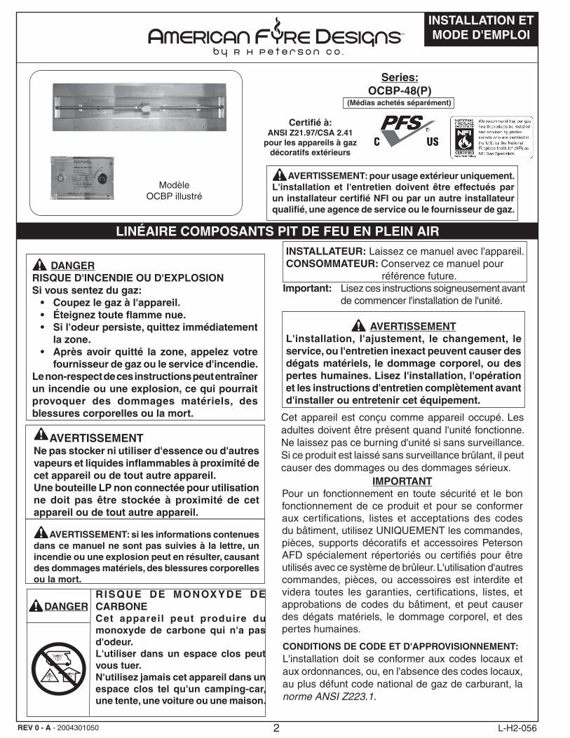

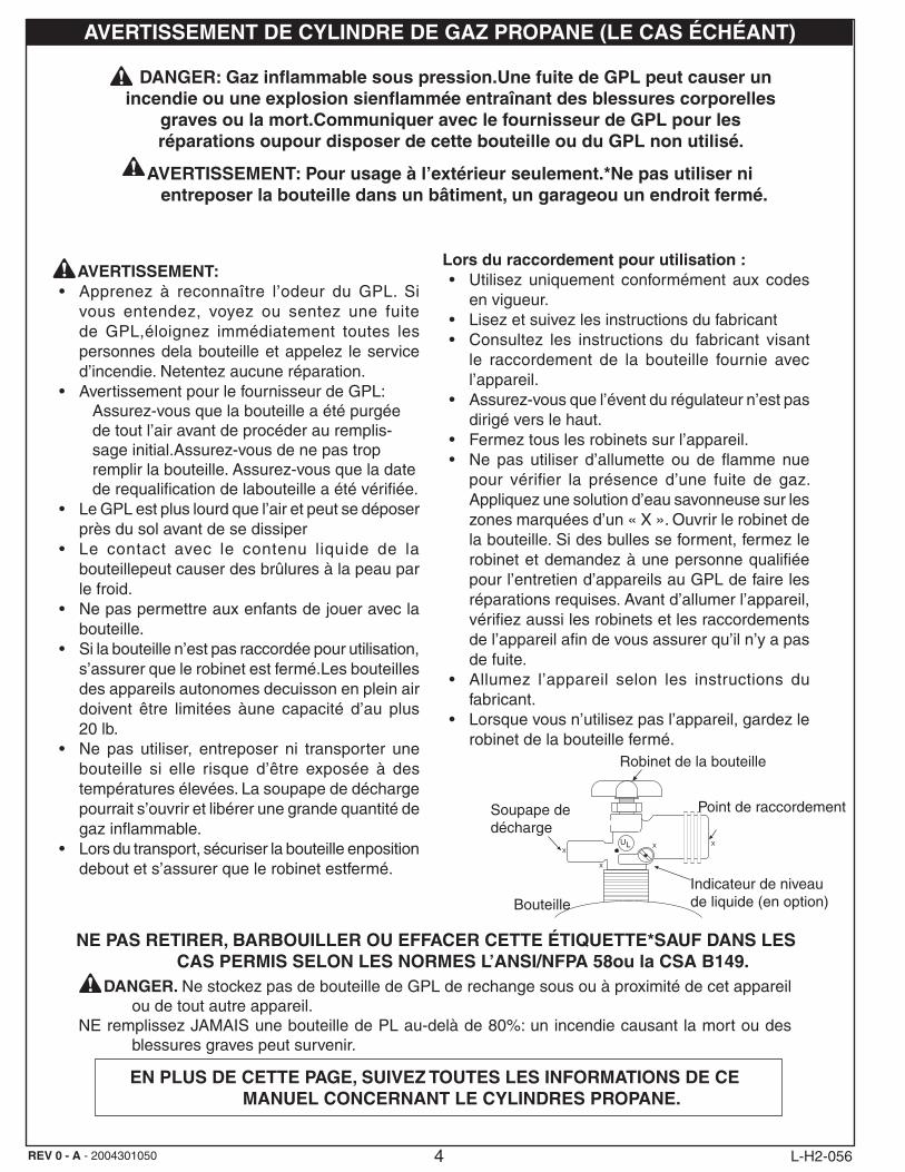


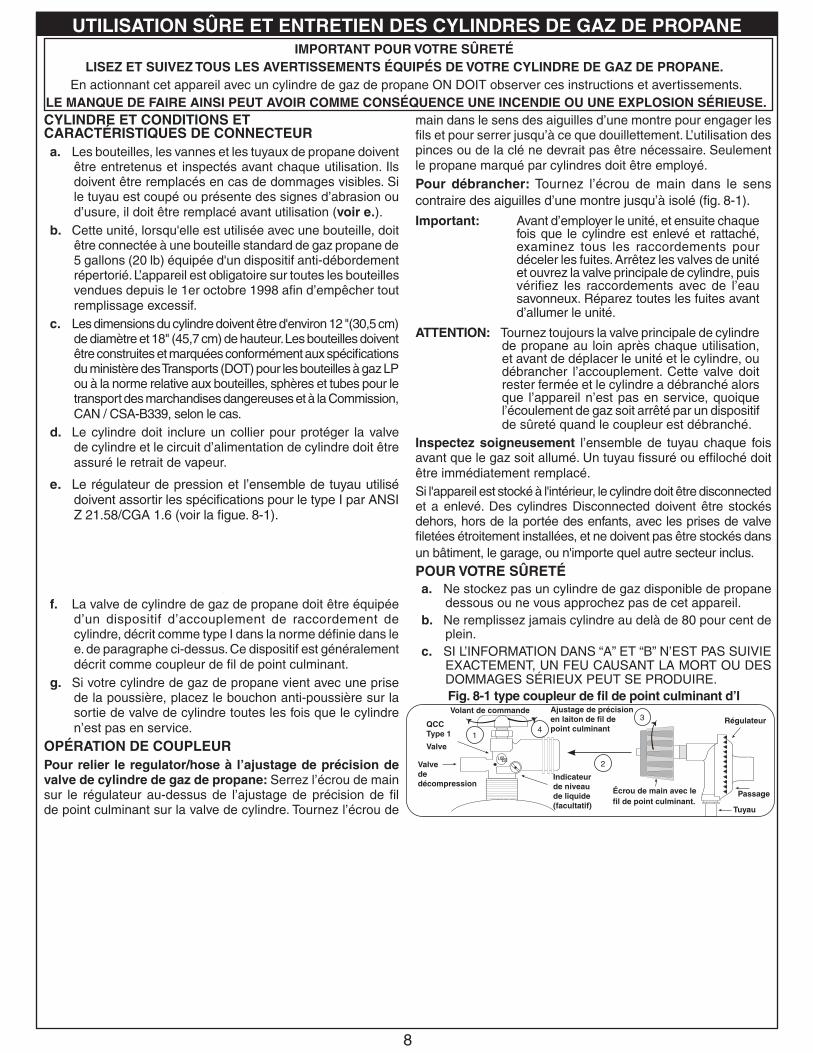
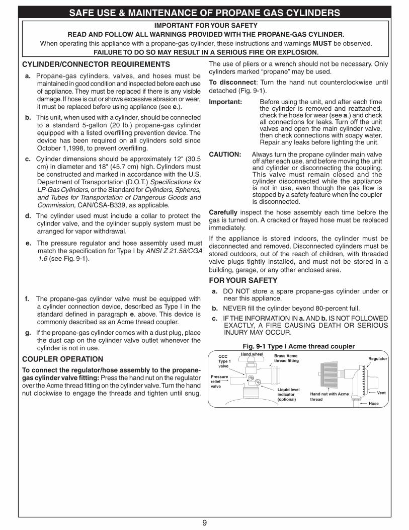
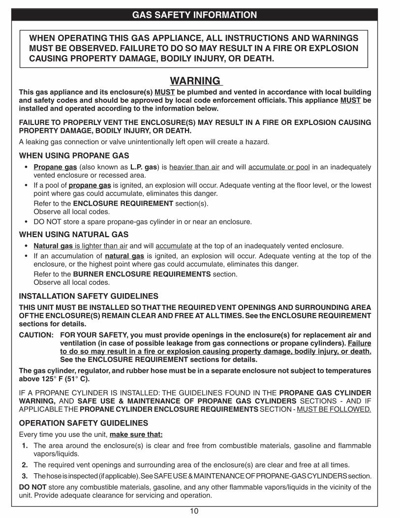


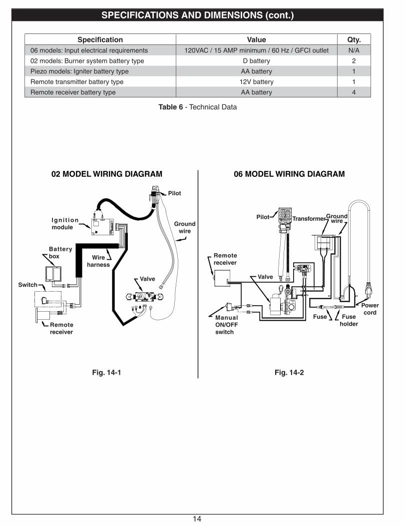


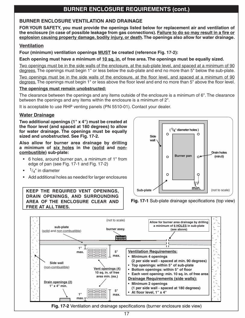


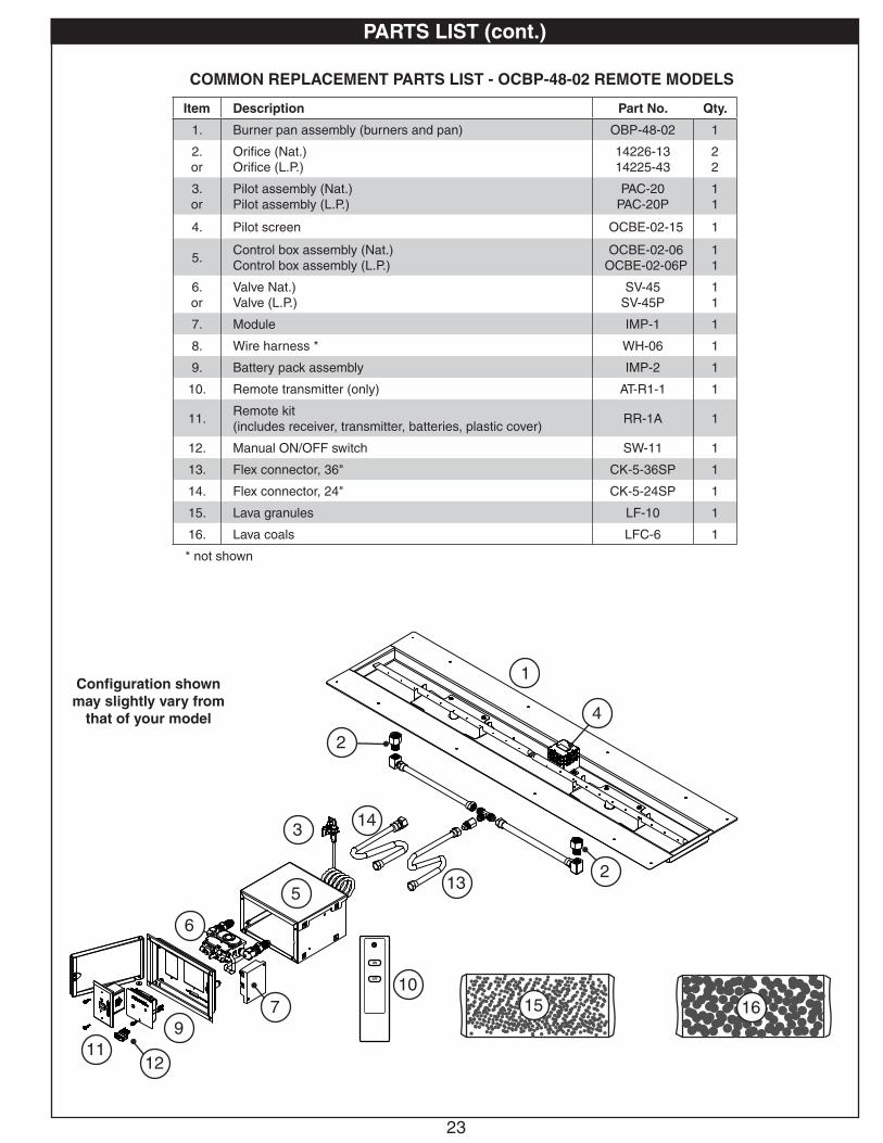
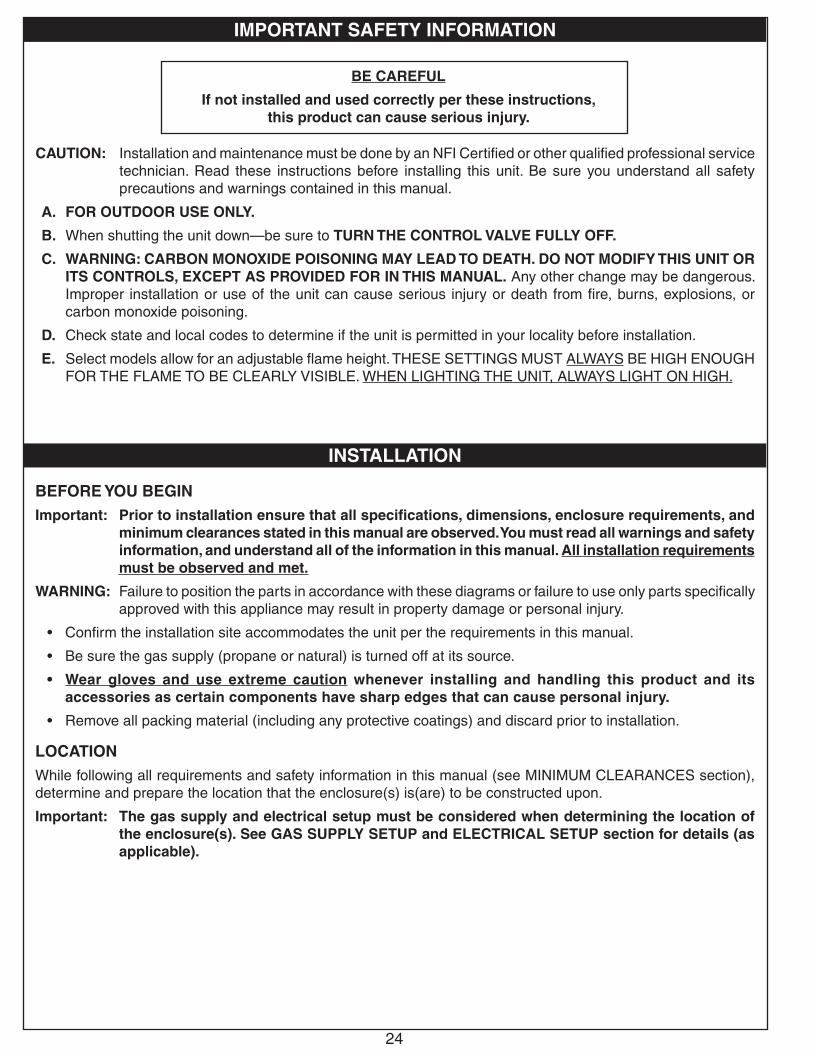
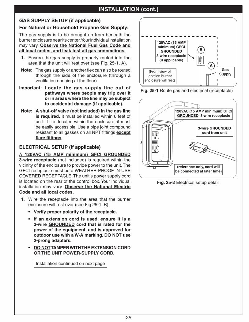


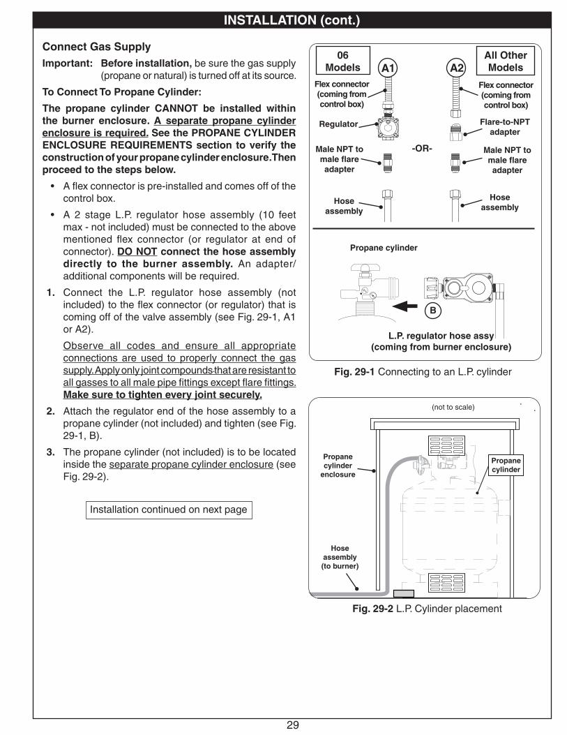
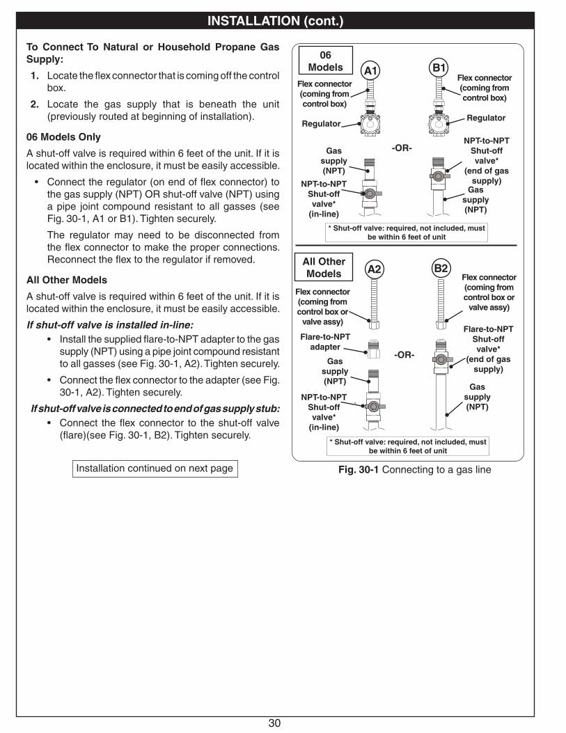
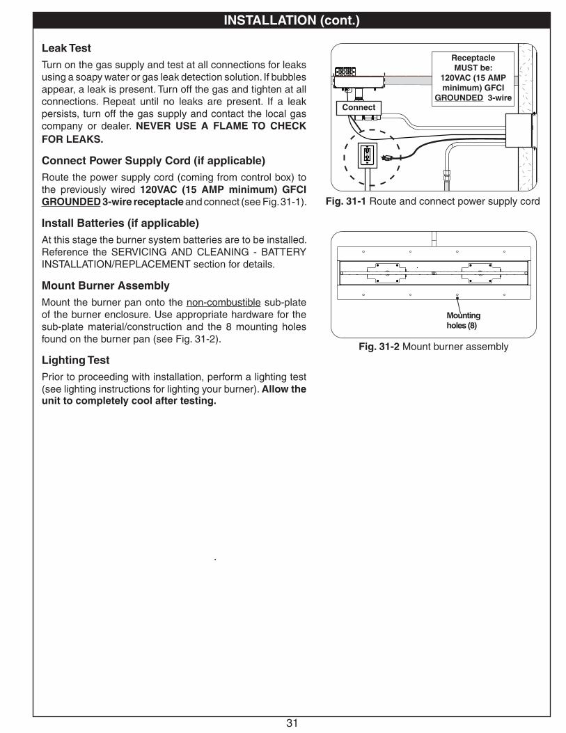
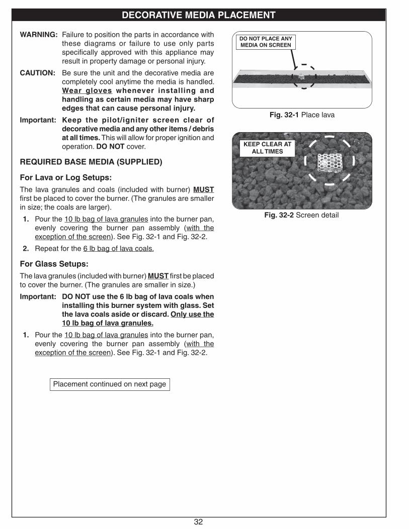


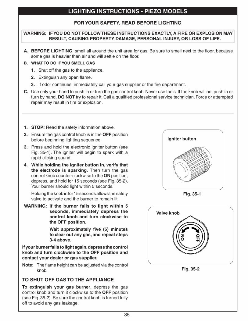

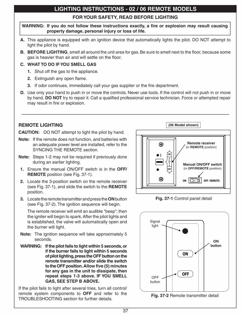


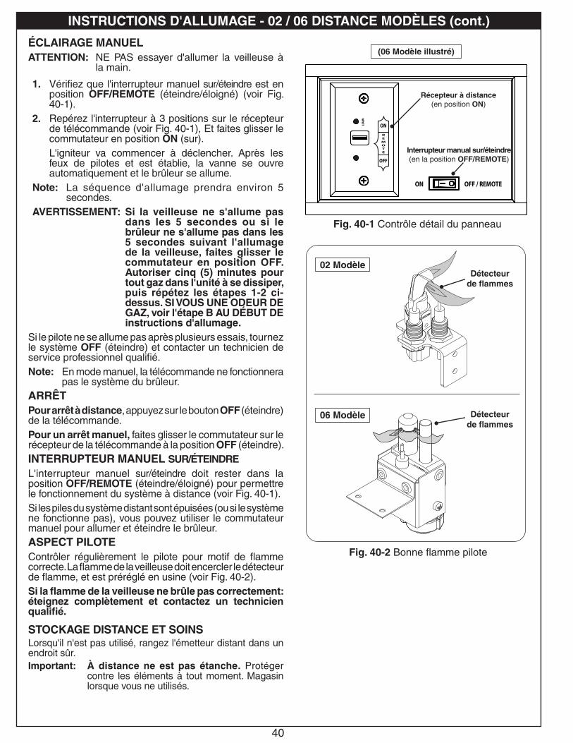

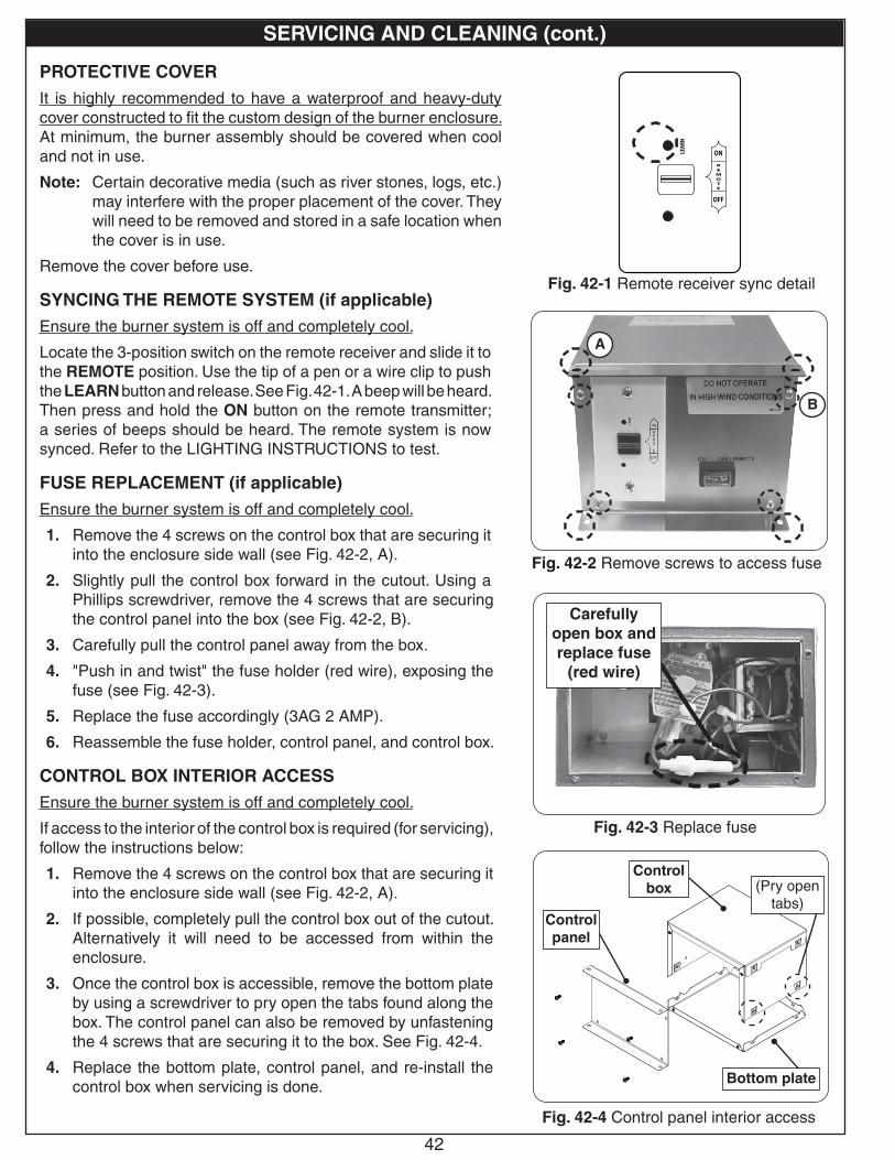
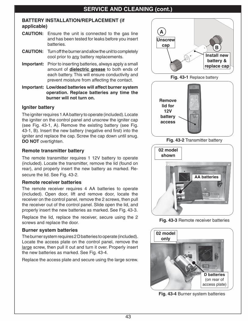

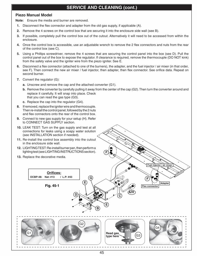
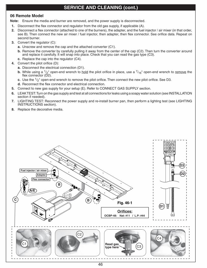

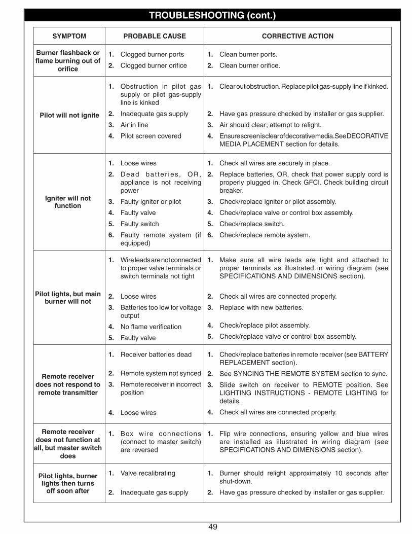


![ENGLISH DEUTSCH FRANÇAIS ITALIANO Lieber Kunde Cher … · [Configuration appareil]/[Config. d’appareil] → [Aff. infos sur appareil]/[Aff. info d’appareil]. ≥Mettez la version](https://static.documents.pub/doc/80x56/5e1cb93ec8c91664312e9886/english-deutsch-franais-italiano-lieber-kunde-cher-configuration-appareilconfig.jpg)