Linear static analysis of perforated plates with round and staggered holes under their self-weights Mustafa Halûk Saraçoğlu*, Uğur Albayrak Online Publication Date: 8 Nov 2015 URL: http://www.jresm.org/archive/resm2015.25me0910.html DOI: http://dx.doi.org/10.17515/resm2015.25me0910 Journal Abbreviation: Res. Eng. Struct. Mat. To cite this article Saraçoğlu MH, Albayrak U. Linear static analysis of perforated plates with round and staggered holes under their self-weights. Res. Eng. Struct. Mat., 2016; 2: 39-47. Disclaimer All the opinions and statements expressed in the papers are on the responsibility of author(s) and are not to be regarded as those of the journal of Research on Engineering Structures and Materials (RESM) organization or related parties. The publishers make no warranty, explicit or implied, or make any representation with respect to the contents of any article will be complete or accurate or up to date. The accuracy of any instructions, equations, or other information should be independently verified. The publisher and related parties shall not be liable for any loss, actions, claims, proceedings, demand or costs or damages whatsoever or howsoever caused arising directly or indirectly in connection with use of the information given in the journal or related means.
Transcript
Linear static analysis of perforated plates with round
Linear static analysis of perforated plates with round and staggered holes under their self-weights
Mustafa Halûk Saraçoğlu*1, Uğur Albayrak2
1Department of Civil Engineering, Dumlupınar University, Kütahya, Turkey 2Department of Civil Engineering, Eskişehir Osmangazi University, Eskişehir, Turkey
Article Info Abstract
Article history: Received 10 Sep 2015 Revised 26 Sep 2015 Accepted 1 Nov 2015
Perforated plates with round holes which are manufactured easily offer the wide area of applications such as metal ceiling tiles, air condition grilles, etc. In this study, optimum hole size and shape of perforated plates with round and staggered holes investigated using mid-point deflections of perforated plates under their self-weights. Analyzed plates are simply supported on their four sides. Analysis results are obtained by using APDL codes for ANSYS. The square perforated plates are examined in terms of mid-point deflections by changing numbers, radii and locations or their holes. The graphics showing the relationship between the number of holes and mid-point deflections of the plates were presented to indicate the effects of geometric discontinuities. The graphics and formulations presented in the study could be useful to determine the design parameters and perforating operations of the perforated square plates with round and staggered holes.
Keywords: Finite element method, Mid-point deflection, Perforated plate, Round and staggered holes.
1. Introduction
Perforated plates with round and staggered holes offer the wide area of applications such as metal ceiling tiles, decorative banisters, air condition grilles, etc. (Fig. 1) According to the latest surveys, most perforated sheets are produced with round holes. Because of the round roles are manufactured relatively easier with aesthetic effects. The circular die for punching sheet can last longer and easy to be manufactured which makes the round hole perforated sheet cheaper than any other perforated sheet with other hole patterns.
Bending of a square plate with a circular hole and circular plate with a circular hole at the center examined in the most important reference for plates and shells [1]. Perforated metal is made through the metal stamping and sheet metal manufacturing process [2]. Round holes are the most economical and extreme open area proportions tend to increase distortion [3]. Round roles are manufactured relatively easier with aesthetic effects. The circular die for punching sheet can last longer and easy to be manufactured which makes the round hole perforated sheet cheaper than any other perforated sheet with other hole patterns [4]. Young and Jo presented equivalent material properties of perforated plate with triangular or square penetration pattern for dynamic analysis [5]. Chen et al. developed the boundary element alternating method to study the stress concentration of a two-dimensional perforated plate [6]. Rens et al. studied the mechanical behavior of perforated plates and simulate by the analysis of homogenized (unperforated) plates [7].
In this study, Lay-In and Lay-On Systems in both Lay-In and Lay-On type suspension systems were examined. The same exposed grid system is utilized with the difference stemming from the tiles and the way the tiles are placed inside the grid. Metal ceiling tiles
Header: ( Font Cambria, 8pt font size, Italic, Centered)
Saraçoğlu and Albayrak / Research on Engineering Structures & Materials 2 (2016) 39-47
40
that are widely produced as thin square plates with multiple circular holes are made of steel or aluminum plates with punching process (Fig. 1).
Fig. 1 Architectural ceiling system examples - metal ceiling tiles
2. Analysis of a Thin Square Plate with Multiple Circular Holes
In classical plate theory, for a transversely loaded plate without axial deformations, bending of a rectangular thin plate, the governing equation has the form
𝜕4w
𝜕𝑥4 + 2 𝜕4w
𝜕𝑥2𝜕𝑦2 + 𝜕4w
𝜕𝑦4 =q(𝑥,𝑦)
𝐷 (1)
where;
𝐷 =E ℎ3
12(1−𝜈2)
is the flexural rigidity, h is the thickness of the plate, E is the Young’s modulus, ν is the Poisson’s ratio and q(x,y) is the external transverse load.
This equation is an equilibrium equation in direction z of a plate carrying uniform distributed load q. In this equation, w is the elastic surface function showing the deflection to be made depending on the x and y coordinates of the mid-plane of the plate.
The boundary conditions for simply supported edges are:
w=0 𝜕2w
𝜕𝑥2 = 0 for x=0 and x=a
w=0 𝜕2w
𝜕𝑦2 = 0 for y=0 and y=a
For an infinitely large plate in a uniform state of stress defined by the bending moments Mx=M and My=0 deflection surface of the plate can be defined as;
w′ =M(𝑥2 − 𝜈 𝑦2)
2 𝐷 (1 − 𝜐2)
to obtain the deflection produced in such a state of pure bending by a circular hole with a radius a (Fig. 2), we assume the material to be removed inside the periphery of the circle.
w′′ = −𝑀 𝑎2
2 𝐷[𝐴 log 𝑟 + (𝐵 + 𝐶
𝑎2
𝑟2) cos 2𝜃] (2)
We can fulfill conditions by choosing the additional deflection in Eq (2)
w = w′ + w′′ (3)
Saraçoğlu and Albayrak / Research on Engineering Structures & Materials 2 (2016) 39-47
41
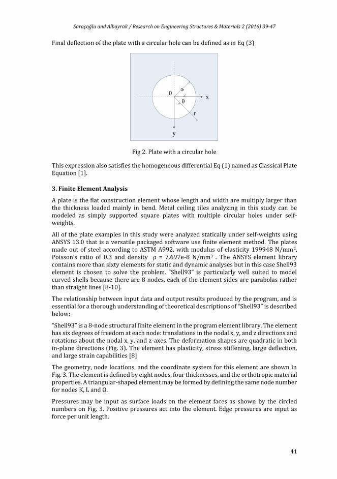
Final deflection of the plate with a circular hole can be defined as in Eq (3)
Fig 2. Plate with a circular hole
This expression also satisfies the homogeneous differential Eq (1) named as Classical Plate Equation [1].
3. Finite Element Analysis
A plate is the flat construction element whose length and width are multiply larger than the thickness loaded mainly in bend. Metal ceiling tiles analyzing in this study can be modeled as simply supported square plates with multiple circular holes under self-weights.
All of the plate examples in this study were analyzed statically under self-weights using ANSYS 13.0 that is a versatile packaged software use finite element method. The plates made out of steel according to ASTM A992, with modulus of elasticity 199948 N/mm2, Poisson’s ratio of 0.3 and density ρ = 7.697e-8 N/mm3 . The ANSYS element library contains more than sixty elements for static and dynamic analyses but in this case Shell93 element is chosen to solve the problem. “Shell93” is particularly well suited to model curved shells because there are 8 nodes, each of the element sides are parabolas rather than straight lines [8-10].
The relationship between input data and output results produced by the program, and is essential for a thorough understanding of theoretical descriptions of “Shell93” is described below:
“Shell93” is a 8-node structural finite element in the program element library. The element has six degrees of freedom at each node: translations in the nodal x, y, and z directions and rotations about the nodal x, y, and z-axes. The deformation shapes are quadratic in both in-plane directions (Fig. 3). The element has plasticity, stress stiffening, large deflection, and large strain capabilities [8]
The geometry, node locations, and the coordinate system for this element are shown in Fig. 3. The element is defined by eight nodes, four thicknesses, and the orthotropic material properties. A triangular-shaped element may be formed by defining the same node number for nodes K, L and O.
Pressures may be input as surface loads on the element faces as shown by the circled numbers on Fig. 3. Positive pressures act into the element. Edge pressures are input as force per unit length.
x
y
r
θ
a0
Saraçoğlu and Albayrak / Research on Engineering Structures & Materials 2 (2016) 39-47
42
Nodes, degrees of freedom, thickness as real constants, modulus of elasticity, Poisson’s ratio, density as material properties are element inputs.
Fig. 3 Geometry of SHELL93 finite element in ANSYS
The solution output associated with the element is in two forms; one is nodal solution the other is element solution.
Several items are illustrated in Fig. 4. Printout includes the moments about the x face (MX), the moments about the y face (MY), and the twisting moment (MXY). The moments are calculated per unit length in the element coordinate system. The element stress directions and force resultants (NX, MX, TX, etc.) are parallel to the element coordinate system.
Fig. 4 Stress output of SHELL93 finite element in ANSYS
Volume of elements, stresses, strains, moments, displacements are some outputs of SHELL93.
Some of assumptions and restrictions of SHELL93 element is as follows:
Shear deflections are included in this element.
The out-of-plane (normal) stress for this element varies linearly through the thickness.
The transverse shear stresses (SYZ and SXZ) are assumed to be constant through the thickness.
The transverse shear strains are assumed to be small in a large strain analysis. (ANSYS, 2005).
APDL (Ansys Parametric Design Language) is a powerful language for optimizing the FEM workflow and provides the user with flexibility and power in creating complex macros.
Saraçoğlu and Albayrak / Research on Engineering Structures & Materials 2 (2016) 39-47
43
APDL codes are developed to create and analyze the plate models systematically in this study.
The plates in this study are modeled with simply-supported boundary conditions on 4 sides and triangular free mesh is used in free meshing operations. The used element edges were depend on meshing areas and enclosed only triangular elements. Finite element mesh dimensions are similar in all of the examples approximately. One side of each mesh element is equal to thickness of the plate in this way total numbers of mesh elements are similar in each model (Fig. 5).
Fig. 5 Mesh geometry of common square perforated pattern layout in ANSYS
The square plates with round and staggered holes analyzed with respect to different number, radius and locations. One side of the perforated square thin plate was changed then the plate thickness was also changed according to plate dimensions. Total open areas of holes are exactly same for each model. The volume and weight of the plates are exactly same, because of total hole area (open area) is equal in all models which were analyzed under the same loads (self-weights).
(a) Model No 1 (2 holes) (b) Model No 2 (8 holes) (c) Model No 3 (18 holes) (d) Model No 4 (32 holes)
(f) Model No 6 (72 holes) (g) Model No 7 (98 holes) (h) Model No 8 (128 holes) (i) Model No 9 (162 holes) (j) Model No 10 (200 holes)
a a a a
a
a
(e) Model No 5 (50 holes)
a
x = y
x
y z
t
a
a
r1
Saraçoğlu and Albayrak / Research on Engineering Structures & Materials 2 (2016) 39-47
44
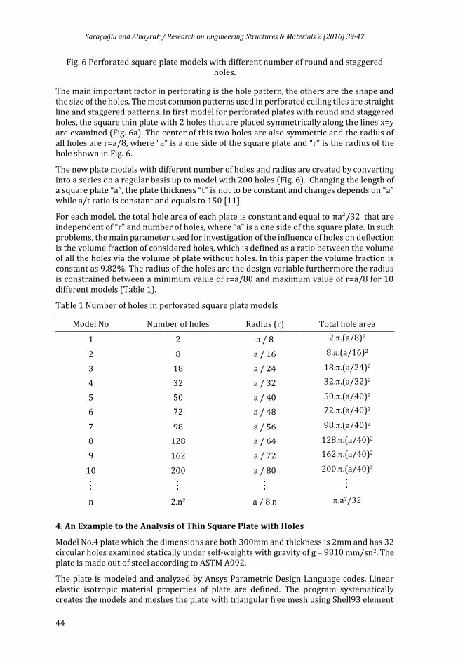
Fig. 6 Perforated square plate models with different number of round and staggered holes.
The main important factor in perforating is the hole pattern, the others are the shape and the size of the holes. The most common patterns used in perforated ceiling tiles are straight line and staggered patterns. In first model for perforated plates with round and staggered holes, the square thin plate with 2 holes that are placed symmetrically along the lines x=y are examined (Fig. 6a). The center of this two holes are also symmetric and the radius of all holes are r=a/8, where “a” is a one side of the square plate and “r” is the radius of the hole shown in Fig. 6.
The new plate models with different number of holes and radius are created by converting into a series on a regular basis up to model with 200 holes (Fig. 6). Changing the length of a square plate “a”, the plate thickness “t” is not to be constant and changes depends on “a” while a/t ratio is constant and equals to 150 [11].
For each model, the total hole area of each plate is constant and equal to πa2/32 that are independent of “r” and number of holes, where “a” is a one side of the square plate. In such problems, the main parameter used for investigation of the influence of holes on deflection is the volume fraction of considered holes, which is defined as a ratio between the volume of all the holes via the volume of plate without holes. In this paper the volume fraction is constant as 9.82%. The radius of the holes are the design variable furthermore the radius is constrained between a minimum value of r=a/80 and maximum value of r=a/8 for 10 different models (Table 1).
Table 1 Number of holes in perforated square plate models
Model No Number of holes Radius (r) Total hole area
1 2 a / 8 2..(a/8)2
2 8 a / 16 8..(a/16)2
3 18 a / 24 18..(a/24)2
4 32 a / 32 32..(a/32)2
5 50 a / 40 50..(a/40)2
6 72 a / 48 72..(a/40)2
7 98 a / 56 98..(a/40)2
8 128 a / 64 128..(a/40)2
9 162 a / 72 162..(a/40)2
10 200 a / 80 200..(a/40)2
n 2.n2 a / 8.n .a2/32
4. An Example to the Analysis of Thin Square Plate with Holes
Model No.4 plate which the dimensions are both 300mm and thickness is 2mm and has 32 circular holes examined statically under self-weights with gravity of g = 9810 mm/sn2. The plate is made out of steel according to ASTM A992.
The plate is modeled and analyzed by Ansys Parametric Design Language codes. Linear elastic isotropic material properties of plate are defined. The program systematically creates the models and meshes the plate with triangular free mesh using Shell93 element
Saraçoğlu and Albayrak / Research on Engineering Structures & Materials 2 (2016) 39-47
45
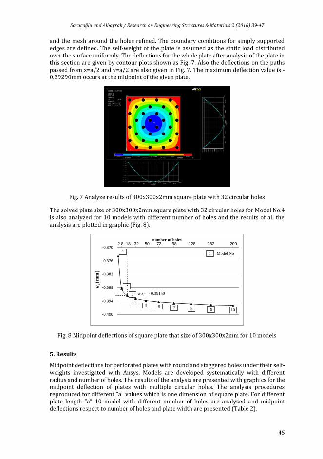
and the mesh around the holes refined. The boundary conditions for simply supported edges are defined. The self-weight of the plate is assumed as the static load distributed over the surface uniformly. The deflections for the whole plate after analysis of the plate in this section are given by contour plots shown as Fig. 7. Also the deflections on the paths passed from x=a/2 and y=a/2 are also given in Fig. 7. The maximum deflection value is -0.39290mm occurs at the midpoint of the given plate.
Fig. 7 Analyze results of 300x300x2mm square plate with 32 circular holes
The solved plate size of 300x300x2mm square plate with 32 circular holes for Model No.4 is also analyzed for 10 models with different number of holes and the results of all the analysis are plotted in graphic (Fig. 8).
Fig. 8 Midpoint deflections of square plate that size of 300x300x2mm for 10 models
5. Results
Midpoint deflections for perforated plates with round and staggered holes under their self-weights investigated with Ansys. Models are developed systematically with different radius and number of holes. The results of the analysis are presented with graphics for the midpoint deflection of plates with multiple circular holes. The analysis procedures reproduced for different “a” values which is one dimension of square plate. For different plate length “a” 10 model with different number of holes are analyzed and midpoint deflections respect to number of holes and plate width are presented (Table 2).
-0.400
-0.394
-0.388
-0.382
-0.376
-0.370
number of holes
0w
mm
1
2
3
45 6 7 8 9 10
1
wo = - 0.39150
: Model No
2 8 18 32 50 72 98 128 162 200
Saraçoğlu and Albayrak / Research on Engineering Structures & Materials 2 (2016) 39-47
46
In this study, for any size of square plate, the number of holes increases the midpoint deflection also increases although total hole area is equal in all models. Number of holes for any plate is proportional to midpoint deflection but it is not linear. In models for less hole numbers; deflections increase rapidly up to 50 holes, beyond this point hole numbers increase, the deflections also begin to increase slightly.
In this study, mid-point deflections of perforated plates with round and staggered holes under their self-weights is investigated. Static analysis in Ansys is performed to evaluate the influence of radius and number of holes. APDL codes are developed to create and analyze the 10 plate models systematically in the study. The plates made out of steel according to ASTM A992, with modulus of elasticity 199948 N/mm2, Poisson’s ratio of 0.3 and density ρ = 7.697e-8 N/mm3 and simply-supported on four sides. After meshing of the problem, number of elements and number of nodes are approximately same for all models. The square plates examined to different number of holes as 2, 8, 18, 32, 50, 72, 98, 128, 162 and 200 respectively and radius and locations are also different. Total surface areas of holes are exactly same for each model. Plate thickness is dependent to one side of the square plate “a” so the analysis results were compared properly. For different plate length “a” as 100 mm, 200 mm, 300 mm, 400 mm and 500 mm respectively; 10 models with different number of holes are analyzed and midpoint deflections respect to number of holes and plate width are presented. The present study demonstrates the effects of geometric discontinuities on thin square perforated plates with round and staggered holes.
As a result of the analysis for 10 models, for any size of square plate, the number of holes increases the midpoint deflection also increases although total hole area is equal in all models. Number of holes increase, the variation of the midpoint deflections decrease asymptotically after 50 holes (Fig. 8). The results of the analysis are used to develop useful and practical graphics for the midpoint deflection of perforated plates with round and staggered holes. For required square plate dimension or number of holes is chosen than midpoint deflection can be easily determined from the graphic.
References
[1] Timoshenko S, Woinowsky-Krieger S. Theory of plates and shells. 2nd edition, Singapore McGraw-Hill, 1959, ISBN 0-07-085820-9.
[2] http://en.wikipedia.org/wiki/Perforated_metal
Saraçoğlu and Albayrak / Research on Engineering Structures & Materials 2 (2016) 39-47
[4] http://www.perforated-sheet.com/holepattern/round-hole-perforated-sheet.html [5] Young MJ, Jo JC. Equivalent material properties of perforated plate with triangular or
square penetration pattern for dynamic analysis. Nuclear Engineering and Technology, 2006; 38(7):689 – 696.
[6] Chen KT, Ting K, Yang WS. Stress analysis of two-dimensional perforated plates using boundary element alternating method. Computers and Structures, 2000; 75:515 – 527. http://dx.doi.org/10.1016/S0045-7949(99)00103-0
[7] Rens BJE, Brekelmans WAM, Baaijens FPT. Homogenization of the elatoplastic behavior of perforated plates. Computers and Structures, 1998; 69:537–545. http://dx.doi.org/10.1016/S0045-7949(98)00120-5
[8] ANSYS (2005). ANSYS commands reference. [9] ANSYS (2005). APDL programmer's guide. [10] ANSYS (2005). Release 10.0 Documentation for ANSYS. [11] Albayrak U, Saraçoğlu MH. Analyzing of thin square plates with multiple circular holes.
Proceedings of the International Symposium on Advances in Applied Mechanics and Modern Information Technology (ISAAM&MIT'11), Baku, Azerbaijan, 79 – 83, 2011.