IEEE TRANSACTIONS ON PLASMA SCIENCE, VOL. 26, NO. 3, JUNE 1998 519 Linear Theory of a Wide-Band Gyro-TWT Amplifier Using Spiral Waveguide Simon J. Cooke and Gregory G. Denisov Abstract—A novel electrodynamic system to realize high effi- ciency and a broad frequency band in a gyro-TWT amplifier at millimeter and microwave frequencies is described. A cylindrical waveguide having a helically grooved wall selectively couples an electromagnetic waveguide mode at a frequency close to cutoff to the forward travelling wave of a lower mode, resulting in an eigenwave with a constant positive group velocity and approximately zero axial wavenumber over a wide frequency band. For a travelling-wave gyroamplifier, such a dispersion charac- teristic permits operation with significantly increased bandwidth and reduced sensitivity to electron-beam axial velocity spread. Numerical calculations will be presented to show the beam- coupled dispersion characteristics, stability, and gain profiles of a simple amplifier, based upon a linearized coupled-wave theory. Index Terms—Coupled waves, gyro-TWT amplifier, linear the- ory, spiral waveguide. I. INTRODUCTION M ICROWAVE and millimeter-wave amplifiers based upon the cyclotron–resonance maser (CRM) interaction are being developed to meet a need for efficient, broad- band, and high-power sources for radar and communications applications. While they offer good power-handling capability, these devices have encountered a number of limitations in the maximum gain and efficiency of their operation. Typically, performance is limited by the existence of parasitic oscillations, which become excited as the electron-beam power is increased. Also, efficiency and bandwidth are reduced by spread in the velocities of electrons in the beam since interaction is with a travelling electromagnetic wave for which the axial wavenumber, and therefore Doppler effects, are significant. These limitations have reduced performance of gyrotron travelling-wave amplifier (gyro-TWT) experiments when compared to the related, highly efficient gyrotron oscillator. A novel electrodynamic system, introducing a spiral cor- rugation in the normally smooth wall of a cylindrical wave- guide, has been proposed [1], [2] to realize high efficiency and a broad frequency band in a gyro-TWT amplifier. We investigate this approach to reduce both susceptibility to oscillation and sensitivity to velocity spread of gyroamplifiers. Manuscript received September 23, 1997; revised February 5, 1998. This work was supported by Dr. S. N. Spark, DERA Malvern, U.K., and the U.S. Office of Naval Research. S. J. Cooke is with the University of Maryland, College Park, MD 20742 USA. G. G. Denisov is with the Russian Academy of Science, Institute of Applied Physics, Nizhnii Novgorod 603600, Russia. Publisher Item Identifier S 0093-3813(98)04265-9. Resonant coupling due to the corrugation between a selected pair of modes creates an eigenwave with a constant positive group velocity and approximately zero axial wavenumber over a wide frequency band. Interaction with this wave offers efficient, broad-band interaction insensitive to degradation due to velocity spread. Many experiments have identified spurious oscillations and insufficient electron-beam quality as major limitations to the performance of gyrotron travelling-wave amplifiers. A number of variations have been investigated both theoretically and ex- perimentally to attempt to reduce susceptibility to oscillations, however, sensitivity to velocity spread of the electron beam has prevented high efficiency being achieved over a wide band- width. The following is a brief summary of research to date. A theory of the gyrotron travelling-wave amplifier was studied by Chu et al. [3] for a cyclotron electron beam interacting with the mode of a cylindrical waveguide. For a cold beam (no velocity spread) with a constant axial magnetic field, they predicted in excess of 50% efficiency for an experimental design at 35 GHz, having a gain bandwidth of 2.6% and 340-kW output power. In an experimental device, in which tapering of both the circuit and magnetic field was used to increase the bandwidth, Barnett et al. [4] obtained 18-dB gain in the linear regime with a bandwidth of 13% at 35 GHz in a cylindrical mode. Tapering of the circuit and magnetic field, while maintaining cyclotron resonance, as a means to widen the bandwidth of gyroamplifiers was first suggested by Bratman et al. [5]. Ferguson et al. [6], [7] investigated a series of gyroamplifier devices and obtained 16% efficiency at a frequency of 5 GHz with a uniform magnetic field, increasing to 26% efficiency with 7% bandwidth using a tapered field. Eckstein et al. [8] ob- tained 7.7% efficiency with 1.3% bandwidth in a 94-GHz gyro- TWT amplifier experiment using a tapered magnetic field. Ganguly and Ahn [9] derived a nonlinear theory for the gyro-TWT interaction in a rectangular waveguide having a variable cross section and considered a two-stage tapered device having an intermediate sever. A predicted efficiency in excess of 50% with 2% relative frequency bandwidth for a cold beam with uniform magnetic field was found to decrease to 37% efficiency, with a bandwidth 1.8% due to the presence of 10% axial velocity spread. With simultaneous waveguide tapering and magnetic field tapering to maintain a “grazing” in- teraction in a similar device, they predicted 40% bandwidth for a cold beam. However, assuming 5% axial velocity spread, this reduced to a bandwidth of 27% [10]. In such a two-stage ex- periment, Park et al. [11] achieved 20% bandwidth over 32–39 GHz with 16% efficiency, using bidirectional tapering of both 0093–3813/98$10.00 1998 IEEE
Transcript
IEEE TRANSACTIONS ON PLASMA SCIENCE, VOL. 26, NO. 3, JUNE 1998 519
Linear Theory of a Wide-Band Gyro-TWTAmplifier Using Spiral Waveguide
Simon J. Cooke and Gregory G. Denisov
Abstract—A novel electrodynamic system to realize high effi-ciency and a broad frequency band in a gyro-TWT amplifier atmillimeter and microwave frequencies is described. A cylindricalwaveguide having a helically grooved wall selectively couplesan electromagnetic waveguide mode at a frequency close tocutoff to the forward travelling wave of a lower mode, resultingin an eigenwave with a constant positive group velocity andapproximately zero axial wavenumber over a wide frequencyband.
For a travelling-wave gyroamplifier, such a dispersion charac-teristic permits operation with significantly increased bandwidthand reduced sensitivity to electron-beam axial velocity spread.Numerical calculations will be presented to show the beam-coupled dispersion characteristics, stability, and gain profiles ofa simple amplifier, based upon a linearized coupled-wave theory.
Index Terms—Coupled waves, gyro-TWT amplifier, linear the-ory, spiral waveguide.
I. INTRODUCTION
M ICROWAVE and millimeter-wave amplifiers basedupon the cyclotron–resonance maser (CRM) interaction
are being developed to meet a need for efficient, broad-band, and high-power sources for radar and communicationsapplications. While they offer good power-handling capability,these devices have encountered a number of limitationsin the maximum gain and efficiency of their operation.Typically, performance is limited by the existence of parasiticoscillations, which become excited as the electron-beam poweris increased. Also, efficiency and bandwidth are reducedby spread in the velocities of electrons in the beam sinceinteraction is with a travelling electromagnetic wave forwhich the axial wavenumber, and therefore Doppler effects,are significant. These limitations have reduced performance ofgyrotron travelling-wave amplifier (gyro-TWT) experimentswhen compared to the related, highly efficient gyrotronoscillator.
A novel electrodynamic system, introducing a spiral cor-rugation in the normally smooth wall of a cylindrical wave-guide, has been proposed [1], [2] to realize high efficiencyand a broad frequency band in a gyro-TWT amplifier. Weinvestigate this approach to reduce both susceptibility tooscillation and sensitivity to velocity spread of gyroamplifiers.
Manuscript received September 23, 1997; revised February 5, 1998. Thiswork was supported by Dr. S. N. Spark, DERA Malvern, U.K., and the U.S.Office of Naval Research.
S. J. Cooke is with the University of Maryland, College Park, MD 20742USA.
G. G. Denisov is with the Russian Academy of Science, Institute of AppliedPhysics, Nizhnii Novgorod 603600, Russia.
Publisher Item Identifier S 0093-3813(98)04265-9.
Resonant coupling due to the corrugation between a selectedpair of modes creates an eigenwave with a constant positivegroup velocity and approximately zero axial wavenumber overa wide frequency band. Interaction with this wave offersefficient, broad-band interaction insensitive to degradation dueto velocity spread.
Many experiments have identified spurious oscillations andinsufficient electron-beam quality as major limitations to theperformance of gyrotron travelling-wave amplifiers. A numberof variations have been investigated both theoretically and ex-perimentally to attempt to reduce susceptibility to oscillations,however, sensitivity to velocity spread of the electron beam hasprevented high efficiency being achieved over a wide band-width. The following is a brief summary of research to date.
A theory of the gyrotron travelling-wave amplifier wasstudied by Chuet al. [3] for a cyclotron electron beaminteracting with the mode of a cylindrical waveguide.For a cold beam (no velocity spread) with a constant axialmagnetic field, they predicted in excess of 50% efficiency foran experimental design at 35 GHz, having a gain bandwidthof 2.6% and 340-kW output power. In an experimental device,in which tapering of both the circuit and magnetic field wasused to increase the bandwidth, Barnettet al. [4] obtained18-dB gain in the linear regime with a bandwidth of 13% at35 GHz in a cylindrical mode. Tapering of the circuitand magnetic field, while maintaining cyclotron resonance, asa means to widen the bandwidth of gyroamplifiers was firstsuggested by Bratmanet al. [5].
Fergusonet al. [6], [7] investigated a series of gyroamplifierdevices and obtained 16% efficiency at a frequency of 5 GHzwith a uniform magnetic field, increasing to 26% efficiencywith 7% bandwidth using a tapered field. Ecksteinet al. [8] ob-tained 7.7% efficiency with 1.3% bandwidth in a 94-GHz gyro-TWT amplifier experiment using a tapered magnetic field.
Ganguly and Ahn [9] derived a nonlinear theory for thegyro-TWT interaction in a rectangular waveguide having avariable cross section and considered a two-stage tapereddevice having an intermediate sever. A predicted efficiencyin excess of 50% with 2% relative frequency bandwidth for acold beam with uniform magnetic field was found to decreaseto 37% efficiency, with a bandwidth 1.8% due to the presenceof 10% axial velocity spread. With simultaneous waveguidetapering and magnetic field tapering to maintain a “grazing” in-teraction in a similar device, they predicted 40% bandwidth fora cold beam. However, assuming 5% axial velocity spread, thisreduced to a bandwidth of 27% [10]. In such a two-stage ex-periment, Parket al. [11] achieved 20% bandwidth over 32–39GHz with 16% efficiency, using bidirectional tapering of both
0093–3813/98$10.00 1998 IEEE
520 IEEE TRANSACTIONS ON PLASMA SCIENCE, VOL. 26, NO. 3, JUNE 1998
the circuit and the magnetic field. Also, in a single-stage exper-iment, they measured a bandwidth of 33% with 10% efficiencyand 20-dB gain [12]. Nguyenet al. [13] discuss the origins ofdetrimental velocity-spread induced effects in these circuits.
Fliflet [14] analyzed the linearized Vlasov equation andnonlinear theories for both TE and TM modes. General non-linear and linearized theories for gyro-TWT amplifiers havingarbitrary cross section were obtained and analyzed for anumber of waveguide cross sections by Liet al. [15].
Barnettet al. [16] reported stabilization of parasitic oscilla-tions by the input drive power, permitting a significant increasein beam current, and achieved 23% efficiency. Chuet al. [17]studied a gyro-TWT amplifier at 36 GHz having a uniformwaveguide and uniform guiding magnetic field. They obtained10% bandwidth and 18.6% efficiency, stabilizing oscillationsat the expense of efficiency by using a beam with low velocityangle,
More recently, Latham and Nusinovich [18], [19] obtaineda very general Hamiltonian formulation applicable togyrotravelling-wave devices, including in their analysis non-linear, multimode, and multifrequency effects in nonuniformwaveguides and nonlinearly tapered magnetic fields. Theiranalysis identifies velocity spread as a serious limitation toamplifier efficiency due to Doppler effects.
The sensitivity of efficiency and bandwidth to velocityspread in all of these studies may be explained as follows. Thecyclotron resonance condition for electrons interacting with awave of frequency and axial wavenumber is
(1)
where
nonrelativistic electron cyclotron fre-quency;harmonic number;
and axial velocity and Lorentz factor, respec-tively, of the electrons.
This relation specifies the phase-matching condition, andwaves having large are therefore susceptible to adegradation of phase-matching of the interaction due tovarying Doppler shifts if there exists a spread of electronaxial velocities.
To improve this situation, we consider the effect of a peri-odic spiral perturbation to the wall of a cylindrical waveguide,chosen such that two modes, one close to cutoff and onepropagating, are resonantly coupled. The spiral wall profile isillustrated in Fig. 1 and described, in a cylindrical coordinatesystem , by the radius function
(2)
where the modification
(3)
describes a sinusoidal spiral having amplitude Here,is the (integer) azimuthal order of the spiral, and
defines the Bragg periodicity wavevector. Resonantcoupling between pairs of waves occurs when their axialwavenumbers and azimuthal orders differ by and ,respectively.
Fig. 1. Spiral corrugated waveguide.
Fig. 2. Coupling of counter-rotating polarized modes by a spiral corrugation.
The spiral perturbation breaks the rotational symmetry ofthe cylindrical guide, and couples the left- and right-handedcomponents of the waves asymmetrically. This creates achirality in the eigenwave dispersion characteristics of theguide at frequencies close to Bragg resonance, making possiblethe existence of an eigenwave having a nonzero group velocitynear , which is not possible with a regular, cylindricallysymmetric waveguide. A related example of symmetry break-ing has been demonstrated previously for a single mode ofa waveguide having a “step and turn” symmetry [20]. In thatwork, the mode cutoff was shifted in axial wavenumber, and itwas proposed that this would create a desirable eigenwave withnegativegroup velocity at zero axial wavenumber to realizea backward-wave oscillator (BWO) having low sensitivity tothe spread of electron velocity. Our analysis differs in that twomodes couple resonantly to form the desired eigenwave andhas the additional attraction that coupling of the electron beamto the absolute instability is suppressed.
For our periodic spiral-corrugated waveguide, Fig. 2illustrates the chirality in a repeated zone dispersiondiagram, showing the splitting of the eigenmodes whichoccurs when upper and lower circularly polarized waveguidemodes are coupled by a spiral perturbation. The lowercoupled branch exhibits the desirable property for a CRMamplifier of having a positive gradient even at , whilebeing well separated from the possibility of gyrotron-likeoscillation at the cutoff frequency of the upper branch. Thispaper investigates the implications of such a waveguidesystem for CRM amplifier devices.
In Sections II and III, a coupled-wave theory for the spiral-corrugated waveguide is developed. In Section II, the fields
COOKE AND DENISOV: LINEAR THEORY OF A WIDE-BAND GYRO-TWT AMPLIFIER 521
in a regular waveguide are represented by an infinite seriesof orthogonal transverse field eigenfunctions, which are usedto reduce Maxwell’s equations to a set of ordinary differentialequations in the modal coefficients. Expanding the fields in thespiral waveguide using the modes of the cylindrical waveguidesimplifies greatly the analysis of the CRM interaction with acyclotron electron beam using the analysis of Fliflet [14]. Itis intended in the near future to apply this analysis to extendthe capability of the time-dependent multimode code MAGY[21] to enable a full time-dependent nonlinear analysis of aspiral-waveguide gyro-TWT to be performed.
To evaluate the coupling between modes due to the spiralwall profile, the method offictitious magnetic sources[22],[23] is used. This provides analytic expressions assumingthe wall perturbation is small. A rigorous theory of wavepropagation due to Tang [24] would be applicable if a deeplygrooved structure must be considered, however, for the depthsof corrugation necessary here, the perturbative method issufficient.
In general, when calculating the propagation characteristicsof a waveguide having some mechanism of coupling betweenmodes, it is necessary to consider only a few modes, describedby a finite set of coefficients and equations. In Section III,a simple two-mode theory is developed to describe simplythe coupled dispersion characteristics of the spiral waveguideand used to determine the conditions necessary to obtain thedesirable travelling-wave mode for CRM amplifier interaction.
This formulation permits the electron beam to be includedalso, using a linearization of the electron equations of mo-tion in the limit of small electromagnetic fields. Section IVdescribes the beam-coupled dispersion characteristics of thespiral waveguide and determines the gain profile due to CRMinteraction with the propagating coupled mode. Sections Vand VI analyze the stability and gain of a simple amplifierusing spiral waveguide and compare with results for a regulargyro-TWT under typical operating conditions.
II. COUPLED-MODE WAVEGUIDE THEORY
A. Modal Expansion of Fields
Oscillatory fields of angular frequency inside a regularwaveguide may be decomposed using the complete set of or-thogonal transverse modes. The axial profile of each transversemode is determined by a pair of complex valued parameters
and having units of voltage and current respec-tively, which describe the amplitude and phase of the electricand magnetic transverse fields. The complete transverse fieldis given by summation over the modes
where the sum is over both TM and TE modes (denotedandrespectively). The functions and are the transverse
field functions defined for a TM mode by
and for a TE mode
The field functions are scaled such that they satisfy theorthonormality condition
over the cross-sectional area of the waveguide. The scalarfunctions and transverse wavevectors satisfy thetwo-dimensional (2-D) Helmholtz eigenvalue equation
with boundary conditions andfor TM and TE modes, respectively ( denotes the
normal derivative at the surface).From the above definitions, Maxwell’s equations for oscilla-
tory fields in the presence of a high-frequency currentmaybe reduced to a set of coupled linear differential equations
(4)
(5)
using the mode impedances and, where is the axial component
of the wavevector.The complete longitudinal fields for TM and TE modes,
respectively, are
B. Mode Coupling by Fictitious Surface Currents
In order to represent fields in the spiral waveguide in termsof the modal coefficients of the cylindrical guide, it is possibleto use the method of fictitious sources to derive the couplingbetween modal coefficients so that the total field satisfies theboundary conditions at the modified wall surface, defined by(2) and (3). The system of coupled linear differential equationsobtained may be analyzed to determine the new eigenmodesof the spiral-corrugated system.
In the modified guide, the individual field eigenmode solu-tions of the original unperturbed guide will no longer matchthe boundary conditions of the new system. This arises becausethese basis functions no longer form a complete set forthe expansion; they are not orthogonal over the perturbedwaveguide cross section and do not satisfy the boundaryconditions at the new waveguide boundary. However, theseboundary conditions can be enforced provided that additionalelectric and magnetic surface currents are assumed to exist in
522 IEEE TRANSACTIONS ON PLASMA SCIENCE, VOL. 26, NO. 3, JUNE 1998
the walls of the new structure sufficient to screen the residualtangential and fields
where is the surface normal unit vector directed from region2 to region 1 at the interface [23]. If the perturbations to theboundary are small compared to the wavelength then, to firstorder, equivalent electric and magnetic surface currents maybe introduced on the boundary of the reference waveguide toaccount for the perturbation [22].
Such electric currents can exist, but are effectively shortcircuited by the metallic wall. That is, they will flow inthe walls of the waveguide to screen the nonzero tangentialmagnetic fields, but will not excite other modes. However,magnetic currents are not physical and are in this sensefictitious. Therefore, equal and opposite magnetic surfacecurrents must be introduced to give a net physical magneticcurrent of zero, and these currents act as sources to exciteother modes. Magnetic current source terms can be includedin the derivation of the transmission line equations in a similarmanner to the electric current, and it is via such fictitiousmagnetic surface currents that we can calculate the couplingterms between modes which ensure that the new boundaryconditions are satisfied for all
If it is assumed that the perturbation to the surface issmall compared to the wavelength and to the corrugationperiod, then only terms linear in the small parameterneed be retained. This assumption may be validated by thefollowing argument. The spiral perturbation may be consideredas a diffraction grating having a sinusoidal profile, withassociated diffraction wavevector Higherorder diffraction terms, corresponding to multiples of thisvector, will have diminishing amplitudes of correspondinglyhigher order in Two basis TE modes having axialwavevectors differing by are chosen to be degenerate, asshown in Fig. 2, and therefore coupling between these modesis well phase matched at frequencies close to the degeneracy.However, higher order coupling terms will, in general, notsatisfy a similar phase-matching condition with a propagatingmode and would not give rise to strong resonant effects.Therefore, the linear, first order diffraction, is dominant.
In the following section, the coupled mode theory is used toobtain linear equations which may be solved for the coupledwaveguide dispersion.
III. T WO-MODE DISPERSIONTHEORY
OF THE SPIRAL-CORRUGATED GUIDE
Coupling coefficients for this form of spiral waveguidehave been derived previously for coupling between pairs oftravelling waves [22], [25]. However, our analysis involvescoupling at frequencies close to a mode cutoff frequency,and the transmission line representation of modes is necessaryto avoid singularities for Coefficients, valid for allfrequencies, for coupling between TE modes are derived hereusing the method of fictitious sources.
For the mode of a uniform cylindrical waveguide,we write the scalar function
where and isthe th nonzero root of The cutoff frequencyfor such a mode is given by Thisdefinition of the modal functions permits us to consider wavesas being circularly polarized. The azimuthal order takesinteger values, positive for right-handed circularly polarizedwaves, negative for left-handed waves, and zero for symmetricmodes. The associated electric and magnetic field functionsare given in Appendix I. Only TE modes will be consideredfurther and ( ) assumed to apply to all mode parameters.
We consider coupling between a pair of cylindrical TEmodes, denoted and such that in the presence ofa spiral wall corrugation described by the radius function (3).The method of fictitious sources, keeping only terms to first or-der in , provides the following set of coupled equations,in which each mode is represented by a current/voltage pair
(6)
where
otherwise
otherwise
The quantities and determine coupling selection rulesfor circularly polarized modes.
These equations contain the-dependent terms andIt is more useful in solving the coupled mode equations in oursimple theory to determine constant coupling coefficients. It ispossible to simplify further the coupling terms for both upperand lower modes following the procedure of Kogelnik andShank [26].
A. Lower Mode Equations
We may assume that the lower mode is propagating at thefrequency of interest and consider the propagation of forwardand backward waves described by voltage amplitudesand , respectively
(7)
(8)
COOKE AND DENISOV: LINEAR THEORY OF A WIDE-BAND GYRO-TWT AMPLIFIER 523
If now we consider that the upper mode is operatingin the vicinity of cutoff and assume resonant coupling
, we may consider the phase-matched couplingrelationships. We define the slowly varying amplitudes
and forforward and backward waves. Neglecting nonresonant terms,the forward and backward components of the lower mode maybe described by the following differential equations:
(9)
(10)
where is a reduced axial wavenumber and
is a coupling term for the spiral corrugation.
B. Upper Mode Equations
For the upper mode, we may also neglect nonresonant termsand write to first order in the perturbation
(11)
where
similar in form to the previous coupling term.In the vicinity of resonance between these two waves,
and, in general, the two coupling coefficients,and , will be similar and only weakly frequency
dependent. Therefore, a single coupling parameter may be usedin our simple theory, without loss of generality, to representthe effective coupling due to the spiral.
C. Dispersion Properties
We have for two modes of the spiral-corrugated waveguidethe fourth-order coupled system of (9)–(11). The dispersionrelation for coupled eigenmodes with-dependencetakes the form
(12)
Therefore, by choosing the spiral azimuthal order suchthat and , we obtain the coupled dispersionrelation for the spiral system
(13)
When choosing the form of the spiral, we are also free to selectthe periodicity to include an offset from exact resonancebetween two modes. This permits some flexibility in theprecise form of the coupled mode, and a small offset flattens
(a)
(b)
Fig. 3. Resonant coupling between two modes of differing azimuthal orderfor (a) resonant coupling and (b) offset coupling. Here,ml 6= mj 6= 0; suchthat �+ = 0; �
�
= 1:
the dispersion around , creating an ideal eigenwave forbroad-band interaction.
Fig. 3(a) and (b) depicts the dispersion characteristics fortwo coupled modes for exact resonant coupling and for a smalloffset. The effect of the offset can be seen in both the frequencyand group velocity for the lower branch wave at
D. Left- and Right-Handed Polarizations
For each nonsymmetric mode of a cylindricalcavity, there may be considered to be two polarizations. It isuseful to consider right- and left-handed circularly polarizedwaves having azimuthal indexes of an opposite sign. For anypair of modes for which and , there will bea pair of opposite rotation having and whichwill give rise to a similar dispersion diagram, but with thebackwardpropagating wave of the lower mode coupled to theupper mode, leading to a coupled wave having negative group
524 IEEE TRANSACTIONS ON PLASMA SCIENCE, VOL. 26, NO. 3, JUNE 1998
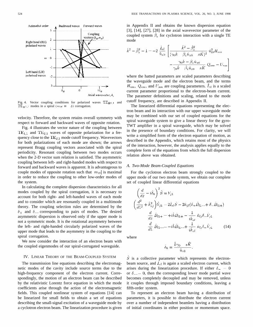
Fig. 4. Vector coupling conditions for polarized wavesTE�2;1 andTE�1;1 modes in a spiral(mB = �3) corrugation.
velocity. Therefore, the system retains overall symmetry withrespect to forward and backward waves of opposite rotation.
Fig. 4 illustrates the vector nature of the coupling betweenand waves of opposite polarization for a fre-
quency close to the mode cutoff frequency. Wavevectorsfor both polarizations of each mode are shown; the arrowsrepresent Bragg coupling vectors associated with the spiralperiodicity. Resonant coupling between two modes occurswhen the 2-D vector sum relation is satisfied. The asymmetriccoupling between left- and right-handed modes with respect toforward and backward waves is apparent. It is advantageous tocouple modes of opposite rotation such that is maximalin order to reduce the coupling to other low-order modes ofthe system.
In calculating the complete dispersion characteristics for allmodes coupled by the spiral corrugation, it is necessary toaccount for both right- and left-handed waves of each modeand to consider which are resonantly coupled in a multimodetheory. The coupling selection rules are determined by the
and corresponding to pairs of modes. The desiredasymmetric dispersion is observed only if the upper mode isnot a symmetric mode. It is the rotational asymmetry betweenthe left- and right-handed circularly polarized waves of theupper mode that leads to the asymmetry in the coupling to thespiral corrugation.
We now consider the interaction of an electron beam withthe coupled eigenmodes of our spiral-corrugated waveguide.
IV. L INEAR THEORY OF THE BEAM-COUPLED SYSTEM
The transmission line equations describing the electromag-netic modes of the cavity include source terms due to thehigh-frequency component of the electron current. Corre-spondingly, the motion of an electron beam can be describedby the relativistic Lorentz force equation in which the modecoefficients arise through the action of the electromagneticfields. This coupled nonlinear system of equations [14] canbe linearized for small fields to obtain a set of equationsdescribing the small-signal excitation of a waveguide mode bya cyclotron electron beam. The linearization procedure is given
in Appendix II and obtains the known dispersion equation[3], [14], [27], [28] in the axial wavevector parameter of thecoupled system for cyclotron interaction with a single TEmode
where the hatted parameters are scaled parameters describingthe waveguide mode and the electron beam, and the terms
and are coupling parameters. is a scaledcurrent parameter proportional to the electron-beam current.The parameter definitions and scaling, related to the modecutoff frequency, are described in Appendix II.
The linearized differential equations representing the elec-tron beam and its interaction with our upper waveguide modemay be combined with our set of coupled equations for thespiral waveguide system to give a linear theory for the gyro-TWT amplifier in a spiral waveguide, which may be solvedin the presence of boundary conditions. For clarity, we willwrite a simplified form of the electron equation of motion, asdescribed in the Appendix, which retains most of the physicsof the interaction, however, the analysis applies equally to thecomplete form of the equations from which the full dispersionrelation above was obtained.
A. Two-Mode Beam-Coupled Equations
For the cyclotron electron beam strongly coupled to theupper mode of our two mode system, we obtain our completeset of coupled linear differential equations
(14)
where
is a collective parameter which represents the electron-beam source, and is again a scaled electron current, whicharises during the linearization procedure. If eitheror , then the corresponding lower mode partial wavebecomes completely decoupled and may be removed, unlessit couples through imposed boundary conditions, leaving afifth-order system.
To represent an electron beam having a distribution ofparameters, it is possible to distribute the electron currentover a number of independent beamlets having a distributionof initial coordinates in either position or momentum space.
COOKE AND DENISOV: LINEAR THEORY OF A WIDE-BAND GYRO-TWT AMPLIFIER 525
Each beamlet may be represented in this linear theory byseparate collective parameters and the field source termreplaced by an average over the distribution weighted bythe corresponding scaled current. This increases the order ofthe equations, however, the following numerical methods ofsolution remain essentially unchanged.
B. Beam-Coupled Dispersion of the Spiral Waveguide
The complete set of linear equations above may be written inmatrix notation, using the abbreviation ,in the form
(15)
where
is a column vector representing the state of the system andis the matrix of coefficients for our equations.
For independent of , this equation admits the formalsolution
(16)
with the transfer matrix
The matrix exponential propagates the state vectorfor alinear system of equations with constant coefficients and maybe defined via its Taylor expansion
where is a square matrix, is a scalar, and is the unitmatrix of dimension equal to that of
We can derive from the coupling matrix the dispersioncharacteristics of the coupled system. For waves having theform
we can write the eigenvalue equation
(17)
and equate to the eigenvalues of the matrix with corre-sponding eigenvectors describing the partial-wave contentof the eigenmodes. Calculating the eigenvalues for
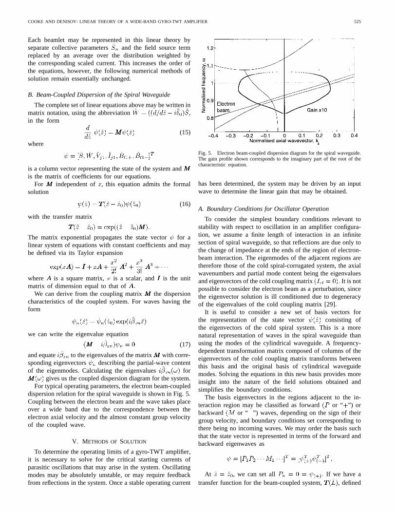
gives us the coupled dispersion diagram for the system.For typical operating parameters, the electron beam-coupled
dispersion relation for the spiral waveguide is shown in Fig. 5.Coupling between the electron beam and the wave takes placeover a wide band due to the correspondence between theelectron axial velocity and the almost constant group velocityof the coupled wave.
V. METHODS OF SOLUTION
To determine the operating limits of a gyro-TWT amplifier,it is necessary to solve for the critical starting currents ofparasitic oscillations that may arise in the system. Oscillatingmodes may be absolutely unstable, or may require feedbackfrom reflections in the system. Once a stable operating current
Fig. 5. Electron beam-coupled dispersion diagram for the spiral waveguide.The gain profile shown corresponds to the imaginary part of the root of thecharacteristic equation.
has been determined, the system may be driven by an inputwave to determine the linear gain that may be obtained.
A. Boundary Conditions for Oscillator Operation
To consider the simplest boundary conditions relevant tostability with respect to oscillation in an amplifier configura-tion, we assume a finite length of interaction in an infinitesection of spiral waveguide, so that reflections are due only tothe change of impedance at the ends of the region of electron-beam interaction. The eigenmodes of the adjacent regions aretherefore those of the cold spiral-corrugated system, the axialwavenumbers and partial mode content being the eigenvaluesand eigenvectors of the cold coupling matrix It is notpossible to consider the electron beam as a perturbation, sincethe eigenvector solution is ill conditioned due to degeneracyof the eigenvalues of the cold coupling matrix [29].
It is useful to consider a new set of basis vectors forthe representation of the state vector consisting ofthe eigenvectors of the cold spiral system. This is a morenatural representation of waves in the spiral waveguide thanusing the modes of the cylindrical waveguide. A frequency-dependent transformation matrix composed of columns of theeigenvectors of the cold coupling matrix transforms betweenthis basis and the original basis of cylindrical waveguidemodes. Solving the equations in this new basis provides moreinsight into the nature of the field solutions obtained andsimplifies the boundary conditions.
The basis eigenvectors in the regions adjacent to the in-teraction region may be classified as forward or “ ”) orbackward or “ ”) waves, depending on the sign of theirgroup velocity, and boundary conditions set corresponding tothere being no incoming waves. We may order the basis suchthat the state vector is represented in terms of the forward andbackward eigenwaves as
At , we can set all If we have atransfer function for the beam-coupled system, , defined
526 IEEE TRANSACTIONS ON PLASMA SCIENCE, VOL. 26, NO. 3, JUNE 1998
in the new basis, then the state vector at the second boundary
where represents only on the columns of At, our boundary conditions require
determined by
so that we must require solutions to
to determine oscillating solutions to the equations.This provides the starting condition for oscillating modes,
which correspond to roots of this nonlinear equation forThe roots were determined by a graphical
method as the intersection of the zero contours of real andimaginary parts of the determinant in the plane [30].
In determining the stability of the system, it is necessaryto consider coupling to both the left- and right-handed wavesas candidates for the onset of oscillation, and it is thereforeimportant to minimize the spatial coupling of the electronbeam to the backward coupled mode to prevent the onset ofabsolute backward-wave instability. Since the scaled current isdependent on the spatial coupling between the electron beamand the mode, and therefore the mode polarization, care mustbe taken when comparing scaled starting currents for modesof opposite rotation.
B. Boundary Conditions for Amplifier Operation
For amplifier operation, the electron-beam current and thefrequency of the input wave are known. It is necessarytherefore to solve for the outgoing waves as functions of theinput waves, which may be determined by solving for thescattering matrix corresponding to the transfer matrix
The scattering matrix is defined such that if
then solving for the outgoing waves as a function of theincoming waves, we obtain
where the component scattering matrices are
(18)
corresponding to port 1 at and port 2 atThe magnitudes of the scattering matrix elements for the
electromagnetic waves represent the amplitude gain of thesystem.
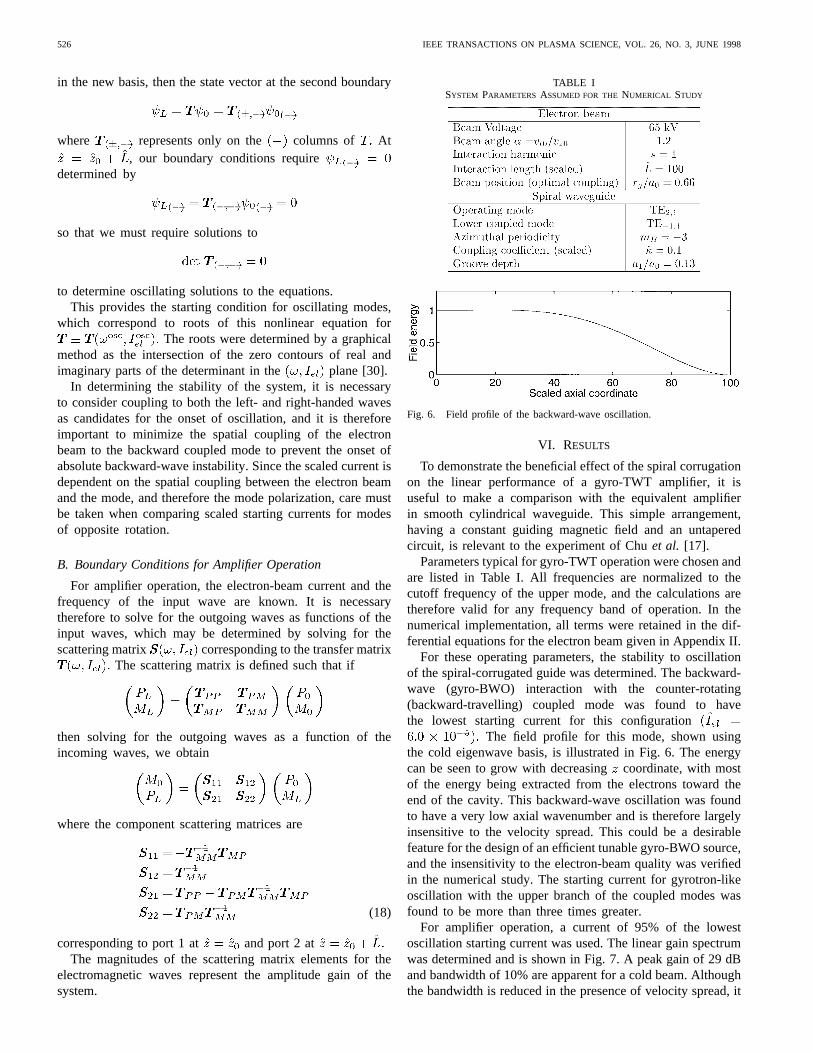
TABLE ISYSTEM PARAMETERS ASSUMED FOR THENUMERICAL STUDY
Fig. 6. Field profile of the backward-wave oscillation.
VI. RESULTS
To demonstrate the beneficial effect of the spiral corrugationon the linear performance of a gyro-TWT amplifier, it isuseful to make a comparison with the equivalent amplifierin smooth cylindrical waveguide. This simple arrangement,having a constant guiding magnetic field and an untaperedcircuit, is relevant to the experiment of Chuet al. [17].
Parameters typical for gyro-TWT operation were chosen andare listed in Table I. All frequencies are normalized to thecutoff frequency of the upper mode, and the calculations aretherefore valid for any frequency band of operation. In thenumerical implementation, all terms were retained in the dif-ferential equations for the electron beam given in Appendix II.
For these operating parameters, the stability to oscillationof the spiral-corrugated guide was determined. The backward-wave (gyro-BWO) interaction with the counter-rotating(backward-travelling) coupled mode was found to havethe lowest starting current for this configuration
The field profile for this mode, shown usingthe cold eigenwave basis, is illustrated in Fig. 6. The energycan be seen to grow with decreasingcoordinate, with mostof the energy being extracted from the electrons toward theend of the cavity. This backward-wave oscillation was foundto have a very low axial wavenumber and is therefore largelyinsensitive to the velocity spread. This could be a desirablefeature for the design of an efficient tunable gyro-BWO source,and the insensitivity to the electron-beam quality was verifiedin the numerical study. The starting current for gyrotron-likeoscillation with the upper branch of the coupled modes wasfound to be more than three times greater.
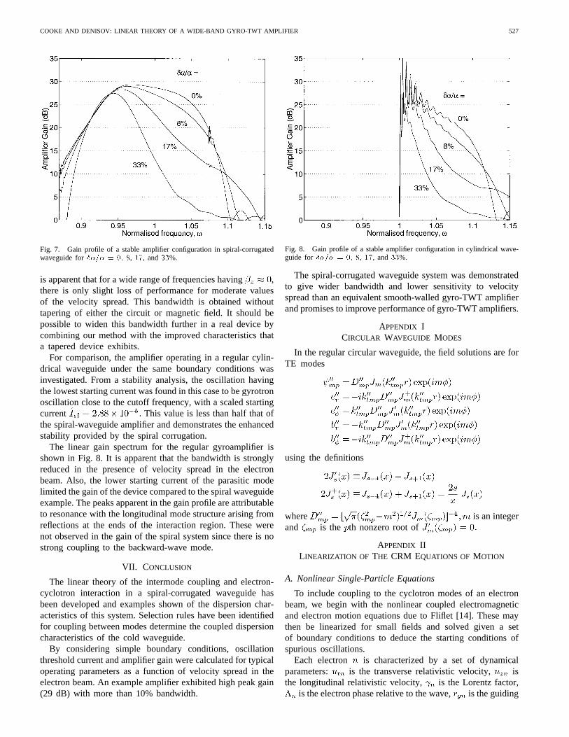
For amplifier operation, a current of 95% of the lowestoscillation starting current was used. The linear gain spectrumwas determined and is shown in Fig. 7. A peak gain of 29 dBand bandwidth of 10% are apparent for a cold beam. Althoughthe bandwidth is reduced in the presence of velocity spread, it
COOKE AND DENISOV: LINEAR THEORY OF A WIDE-BAND GYRO-TWT AMPLIFIER 527
Fig. 7. Gain profile of a stable amplifier configuration in spiral-corrugatedwaveguide for��=� = 0; 8, 17, and33%.
is apparent that for a wide range of frequencies having ,there is only slight loss of performance for moderate valuesof the velocity spread. This bandwidth is obtained withouttapering of either the circuit or magnetic field. It should bepossible to widen this bandwidth further in a real device bycombining our method with the improved characteristics thata tapered device exhibits.
For comparison, the amplifier operating in a regular cylin-drical waveguide under the same boundary conditions wasinvestigated. From a stability analysis, the oscillation havingthe lowest starting current was found in this case to be gyrotronoscillation close to the cutoff frequency, with a scaled startingcurrent This value is less than half that ofthe spiral-waveguide amplifier and demonstrates the enhancedstability provided by the spiral corrugation.
The linear gain spectrum for the regular gyroamplifier isshown in Fig. 8. It is apparent that the bandwidth is stronglyreduced in the presence of velocity spread in the electronbeam. Also, the lower starting current of the parasitic modelimited the gain of the device compared to the spiral waveguideexample. The peaks apparent in the gain profile are attributableto resonance with the longitudinal mode structure arising fromreflections at the ends of the interaction region. These werenot observed in the gain of the spiral system since there is nostrong coupling to the backward-wave mode.
VII. CONCLUSION
The linear theory of the intermode coupling and electron-cyclotron interaction in a spiral-corrugated waveguide hasbeen developed and examples shown of the dispersion char-acteristics of this system. Selection rules have been identifiedfor coupling between modes determine the coupled dispersioncharacteristics of the cold waveguide.
By considering simple boundary conditions, oscillationthreshold current and amplifier gain were calculated for typicaloperating parameters as a function of velocity spread in theelectron beam. An example amplifier exhibited high peak gain(29 dB) with more than 10% bandwidth.
Fig. 8. Gain profile of a stable amplifier configuration in cylindrical wave-guide for ��=� = 0; 8, 17, and 33%.
The spiral-corrugated waveguide system was demonstratedto give wider bandwidth and lower sensitivity to velocityspread than an equivalent smooth-walled gyro-TWT amplifierand promises to improve performance of gyro-TWT amplifiers.
APPENDIX ICIRCULAR WAVEGUIDE MODES
In the regular circular waveguide, the field solutions are forTE modes
using the definitions
where is an integerand is the th nonzero root of
APPENDIX IILINEARIZATION OF THE CRM EQUATIONS OF MOTION
A. Nonlinear Single-Particle Equations
To include coupling to the cyclotron modes of an electronbeam, we begin with the nonlinear coupled electromagneticand electron motion equations due to Fliflet [14]. These maythen be linearized for small fields and solved given a setof boundary conditions to deduce the starting conditions ofspurious oscillations.
Each electron is characterized by a set of dynamicalparameters: is the transverse relativistic velocity, isthe longitudinal relativistic velocity, is the Lorentz factor,
is the electron phase relative to the wave, is the guiding
528 IEEE TRANSACTIONS ON PLASMA SCIENCE, VOL. 26, NO. 3, JUNE 1998
center radius, and is the Larmor radius whereis the nonrelativistic cyclotron frequency.
For a mode interacting with a single harmonicof acyclotron electron beam, the equations of motion, neglectingmotion of the guiding center, are as follows.
For each electron
where
represents spatial coupling of the electron beam to the modeand is the mode normal-ization constant. The functions and are definedin Appendix I.
For the TE electromagnetic mode, denoted, driven by atotal electron current
describe the evolution with including the electron currentsource term, where represents an average over theensemble of electrons.
For an unbunched beam, the electrons are distributed uni-formly over all initial phases in the rangeFurthermore, the average may be taken over an ensemble ofelectrons having a distribution of initial electron energies orbeam Clearly, the electron equations of motionare not independent: for example, we have a relationshipbetween energy and momenta for each particle specified bythe relativistic relationship such that
holds for each electron.If we assume that all electrons have the same guiding center
radius and define , then it is possible
to rescale the parameters in these equations to include someof the coupling constants, to give the simpler form
where quantities are scaled to the cutoff frequency of the modeas follows:
and
where is the real electron-beam current,is the free-space impedance, and is the Alfven current
kA
For first harmonic operation , the Larmor orbits areoften small, , so that and
and the equations simplify considerably.
B. Linearized Single-Particle Equations
While the nonlinear equations describe completely the inter-action between an ensemble of electrons and a TE waveguidemode, it is useful to determine initially the behavior in thelimit of small field amplitudes. The use of collective variablespermits us to perform the averaging over initial phase of the
COOKE AND DENISOV: LINEAR THEORY OF A WIDE-BAND GYRO-TWT AMPLIFIER 529
electrons, and we can obtain a linear system of equations oflow order.
If we assume that changes in the electron parameters fromtheir uncoupled values are small and linear, we may write
for small parameter , where the parameter describesthe linear variation of with The field parameters in thiscase may be taken to be of the same order, such that
If we assume all of the electrons have the same initial energyand momentum components and that their initial phasesare distributed evenly in phase, then our equations may belinearized to first order in to give
where and we havethe collective variables defined according to the averages overthe distribution
and the parameter
C. Equations of Minimum Order
It is possible to simplify further, noting that the aboveequations for the electrons are not linearly independent, andwe may define linear parameters
and
such that these equations reduce to
where
and and are the scaledguiding center and Larmor radii.
For eigenwaves having -dependence , theseequations admit the dispersion relation
equivalent to that deduced from the linearized Vlasov equationfor a cold thin annular beam [27], [28] given the originalassumptions used to derive the nonlinear equations of motion.The term drives the instability, while the and
terms represent stabilizing corrections. In the vicinity ofcyclotron resonance, defined by (1), the denominator term issmall
and therefore the and terms are successively smaller.
530 IEEE TRANSACTIONS ON PLASMA SCIENCE, VOL. 26, NO. 3, JUNE 1998
If we neglect these terms and assume that the axialwavenumber of the cold dispersion is known, then aparticularly simple form may be obtained for the coupledequations
where for wave phase velocity the electron-beamparameter is defined
and
is a single, frequency-dependent coupling parameter whichis directly related to the electron-beam current. This formencapsulates most of the essential physics of the interaction ina single value for the electron coupling, as the scaled currentparameter varies only slightly over a moderate frequencyrange. This proved useful in an initial analysis of solutionsto these equations for the spiral waveguide.
ACKNOWLEDGMENT
The authors would like to thank Dr. B. Levush of the NavalResearch Laboratory, Washington, DC, for his encouragementin the completion and publication of this work.
REFERENCES
[1] G. G. Denisov and S. J. Cooke, “New microwave system for gyro-TWT,” in Proc. 21st Int. Conf. Infrared and Millimeter Waves, July1996, p. AT2.
[2] G. G. Denisov, V. L. Bratman, A. D. R. Phelps, and S. V. Samsonov,“Gyro-TWT with a helical operating waveguide: New possibilities toenhance efficiency and frequency bandwidth,” inProc. 22nd Int. Conf.Infrared and Millimeter Waves, July 1997, pp. 289–290.
[3] K. R. Chu, A. T. Drobot, V. L. Granatstein, and J. L. Seftor, “Charac-teristics and optimum operating parameters of a gyrotron traveling waveamplifier,” IEEE Trans. Microwave Theory Tech., vol. MTT-27, no. 2,pp. 178–187, 1979.
[4] L. R. Barnett, Y. Y. Lau, K. R. Chu, and V. L. Granatstein, “Anexperimental wide-band gyrotron traveling wave amplifier,”IEEE Trans.Electron Devices, vol. ED-28, no. 7, pp. 872–875, 1981.
[5] V. L. Bratman, M. A. Moiseev, M. I. Petelin, and R.E. Erm, “Theoryof gyrotrons with a nonfixed structure of the high-frequency field,”Izv.Vyssh. Ucheb. Zaved. Radiofiz., vol. 16, no. 4, pp. 622–630, 1973.
[6] P. E. Ferguson, G. Valier, and R. S. Symons, “Gyrotron-TWT operatingcharacteristics,”IEEE Trans. Microwave Theory Tech., vol. MTT-29,no. 8, pp. 794–799, 1981.
[7] R. S. Symons, H. R. Jory, S. J. Hegji, and P. E. Ferguson, “Anexperimental gyro-TWT,”IEEE Trans. Microwave Theory Tech., vol.MTT-29, no. 3, pp. 181–184, 1981.
[8] J. N. Eckstein, D. W. Latshaw, and D. S. Stone, “95 GHz gyro travelingwave tube,” Final Rep. to the Ballistic Missile Defense AdvancedTechnology Center, Huntsville, AL, 1983.
[9] A. K. Ganguly and S. Ahn, “Self-consistent large signal theory of thegyrotron travelling wave amplifier,”Int. J. Electron., vol. 53, no. 6, pp.641–658, 1982.
[10] , “Large-signal theory of a two-stage wideband gyro-TWT,”IEEETrans. Electron Devices, vol. ED-31, no. 4, pp. 474–480, 1984.
[11] G. S. Park, J. J. Choi, S. Y. Park, C. M. Armstrong, A. K. Ganguly,R. H. Kyser, and R. K. Parker, “Gain broadening of two-stage taperedgyrotron traveling wave tube amplifier,”Phys. Rev. Lett., vol. 74, no.12, pp. 2399–2402, 1995.
[12] G. S. Park, S. Y. Park, R. H. Kyser, C. M. Armstrong, A. K. Ganguly,and R. K. Parker, “Broadband operation of a Ka-band tapered gyro-traveling wave amplifier,”IEEE Trans. Plasma Sci., vol. 22, no. 5, pp.536–543, 1994.
[13] K. T. Nguyen, G. S. Park, J. J. Choi, S. Y. Park, and R. K. Parker,“Effects of beam velocity spread on two-stage tapered gyro-TWTamplifier,” IEEE Trans. Electron Devices, vol. 43, no. 4, pp. 655–660,1996.
[14] A. Fliflet, “Linear and nonlinear theory of Doppler-shifted cyclotronresonance maser based on TE and TM waveguide modes,”Int. J.Electron., vol. 61, no. 6, pp. 1049–1080, 1986.
[15] Q. F. Li, S. Y. Park, and J. L. Hirshfield, “Theory of gyrotron traveling-wave amplifiers,”IEEE Trans. Microwave Theory Tech., vol. MTT-34,no. 10, pp. 1044–1058, 1986.
[16] L. R. Barnett, L. H. Chang, H. Y. Chen, K. R. Chu, W. K. Lau, and C. C.Tu, “Absolute instability competition and suppression in a millimeter-wave gyrotron traveling-wave tube,”Phys. Rev. Lett., vol. 63, no. 10,pp. 1062–1065, 1989.
[17] K. R. Chu, L. R. Barnett, W. K. Lau, L. H. Chang, and H. Y. Chen,“A wide-band millimeter-wave gyrotron traveling-wave amplifier exper-iment,” IEEE Trans. Electron Devices, vol. 37, no. 6, pp. 1557–1560,1990.
[18] P. E. Latham and G. S. Nusinovich, “Theory of relativistic gyro-traveling wave devices,”Phys. Plasmas, vol. 2, no. 9, pp. 3494–3510,1995.
[19] , “Stability analysis of relativistic gyro-traveling wave devices,”Phys. Plasmas, vol. 2, no. 9, pp. 3511–3523, 1995.
[20] K. J. Bunch, R. W. Grow, and J. M. Baird, “Backward-wave interactionusing step periodic structures,”Int. J. Infrared Millimeter Waves, vol. 9,no. 7, pp. 609–629, 1988.
[21] M. Botton, T. M. Antonsen, Jr., B. Levush, K. T. Nguyen, and A. N.Vlasov, “MAGY: A time-dependent code for simulation of slow andfast microwave sources,” this issue, pp. 882–892.
[22] N. F. Kovalev, I. M. Orlova, and M. I. Petelin, “Wave transformationin a multimode waveguide with corrugated walls,”Izv. Vyssh. Ucheb.Zaved. Radiofiz., vol. 11, no. 5, pp. 783–786, 1968.
[23] F. Sporleder and H.-G. Unger,Waveguide Tapers Transitions and Cou-plers. London, U.K.: IEE, no. 6, 1979.
[24] C. C. H. Tang, “On the wave propagation and mode conversionin helically corrugated multimode circular waveguide,”IEEE Trans.Microwave Theory Tech., vol. MTT-14, no. 6, pp. 275–284, 1966.
[25] G. G. Denisov and M. G. Reznikov, “Corrugated cylindrical resonatorsfor short-wavelength relativistic microwave oscillators,”Izv. Vyssh.Ucheb. Zaved. Radiofiz., vol. 25, no. 5, pp. 562–569, 1982.
[26] H. Kogelnik and C. V. Shank, “Coupled-wave theory of distributedfeedback lasers,”J. Appl. Phys., vol. 43, no. 5, pp. 2327–2335, 1972.
[27] J. Y. Choe and S. Ahn, “General mode analysis of a gyrotron dispersionequation,”IEEE Trans. Electron Devices, vol. ED-28, no. 1, pp. 94–102,1981.
[28] C. S. Kou, Q. S. Wang, D. B. McDermott, A. T. Lin, K. R. Chu, andN. C. Luhmann, Jr., “High-power harmonic gyro-TWTs—Part I: Lineartheory and oscillation study,”IEEE Trans. Plasma Sci., vol. 20, no. 3,pp. 155–162, 1992.
[30] W. H. Press, S. A. Teukolsky, W. T. Vetterling, and B. P. Flannery,Numerical Recipes in C, 2nd ed. Cambridge, U.K.: Cambridge Univ.Press, 1992.
Simon J. Cookewas born in Glasgow, U.K., on July 12, 1967. He received theB.Sc. (Hons.) degree in physics from the University of Strathclyde, Glasgow,in 1988 and the D.Phil. degree from the University of Oxford, Oxford, U.K.,in 1992. His doctoral research involved experimental and theoretical analysisof the optical properties of nanoscale organic thin films.
His recent research has included numerical modeling of relativistic electronbeam and high-power microwave physics at the University of Strathclydefrom 1992 to 1995 and with the University of Maryland since 1995.
Gregory G. Denisov, for a photograph and biography, see this issue, p. 518.