www.osram.com/prevaled 09/2017 ww w w w ww ww ww ww ww w ww ww w w w ww ww w w w w w ww ww w ww ww w ww ww ww ww ww ww w w w w w w ww ww ww w w w w w w ww w ww w w w w w ww ww ww w ww w w w w w w ww ww w w w w w w w w w w w ww ww w ww w ww w w w ww w w w w ww ww ww w w ww w w w w ww w ww ww ww. w. w. w. w w. w. w w w w. w. w w w. w w. w. w. w w. w w. w w w w w. w w w w w w w w. w w w w w w w w. w w w w w. w. w w w w. . w w w w w w w os os os os os os os os os s os os os os os s os o o os o o os os o os os os os s os os os s os o os s os os s os s s os os os os s os s s s o ra ra ra ra a a a a ra ra ra a a a a ra ra a a a ra ra ra a a ra ra a a a ra ra ra ra a a ra ra a a ra a a a ra a ra ra a ra ra ra a ra a a a a a a a ra a a ra r ra a ra a ra a ra a am m m m m m m m m. m m. m. m. m. m. m m m m. m. m. m. m m m m m m m. m m. m m m. m. m m m m m m. m. m m m m. m m m m m m. m m. m m m m m m m m m m m. m m m m m m m m m m m m m m. m m m. m. m m co co co co co co co co co co co co co co co co co co co c co co co co co co c c co co co co co c c c c c c co o c c c co o o co co o co c com/ m/ m/ m/ m/ m/ m/ m/ m/ m/ m/ m/ m/ / / / / m/ m/ m/ / / / m/ m/ m/ m/ m m/ m/ / / / m/ m/ m/ m m m/ m/ / / / m m m/ m/ / / m m/ m/ m/ / / m/ / m m/ m m/ m m m m m/ /p p p p p pr p p p p p pr r p p p p p p pr pr r r p p p pr pr r r p pr pr r p p pr p p p p pr r p p pr pr p pr r pr r r p pr r p p pr r pr p p p pr r p p p p p pr pr r p pr r pr r p pr r ev e ev ev ev ev ev ev ev ev ev ev ev ev ev ev ev ev ev ev ev v e ev ev ev ev v e l l l l l l l al a al al al l al al al a al al al al al al l al al al al al a al al al al a a a a a ed ed ed d d d ed d d d d d ed ed ed d d d ed ed ed d ed e ed d ed d d ed d d d d d d d d d e ed e ed d ed ed d d d d ed d d d ed ed d d e e ed d ed d ed 09 9/2 / 01 7 7 www.osram.com/prevaled 01/2018 Technical application guide PrevaLED ® Linear G4 Light is OSRAM
LiLiLiLiLiLiLiLLLiiLLLLLiLiLiiLLLLLiLLiLiLiLLiLiLiLLLiLiLiLii hghhghghghghggggggghhgghghhhghghhghghghghghhghghghhghghgg ttttttttttttttttttttttttttttttt t t tt iiisisiiisiiiiiiiisiiisisississsssssisssisssssssisssisiisssissssiiiiiiiiiiiii OOOOOOOOOOOOOOOOOOOOOOOOOOOOOOOOOOOOOOOOOOOOOOOOSRSRSRSRSRRRRRRRRRRRRRRRRRSRRRRRRRSRSRRRRRRRRRRRRRRRRRRSRRRSRSRSRSSRSRSRSRSRSRSSRSRSRSSRSRSRSRSRSSSSRSSRSSSRRRRSRSSSRSRSRSRRRRRSRSRSRSRSRSRRRRSRSRSRRRRRRRRRRRSRSRSRRRSRSRRRRSSRRRRRRRRRRRRRAAAAAAMAMAMAMAMAMMMMAAAMMAMAMAAMMAAMAAAAMMMAAAAAMMAAMAAMAAAMAMAMAMAAMAMAAAAMAAAMAMAAMAMMAMAAAAAMAMMMMAAAMAAAAAMMMMMMMMMAAMAAAMAMAMMMMMMAMAMAMAMAMAMAAMAMAMAMM
www.osram.com/prevaled
01/2018
Technical application guide
PrevaLED® Linear G4
Light is OSRAM
2
Contents
1 Introduction 03
1.1 PrevaLED® Linear G4 03
1.2 System solution 03
1.3 Features and benefi ts 03
1.4 LED module portfolio and nomenclature 04
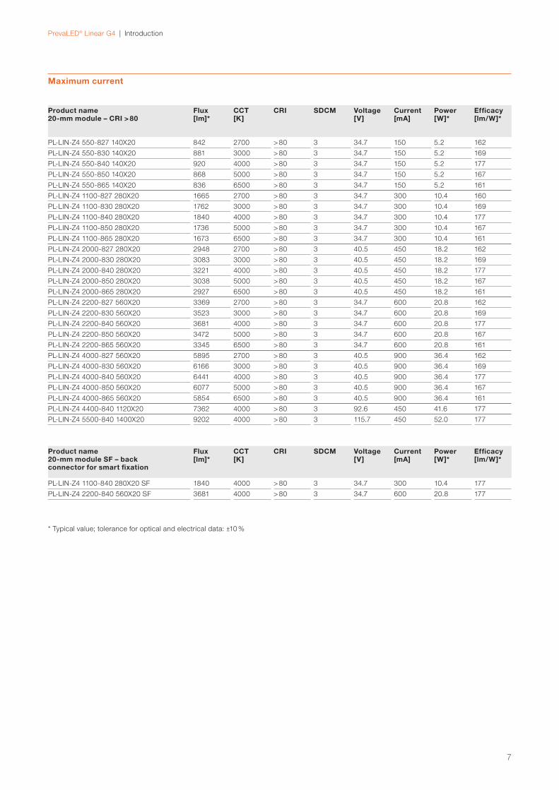
1.5 Electrical and optical data at typical conditions 05
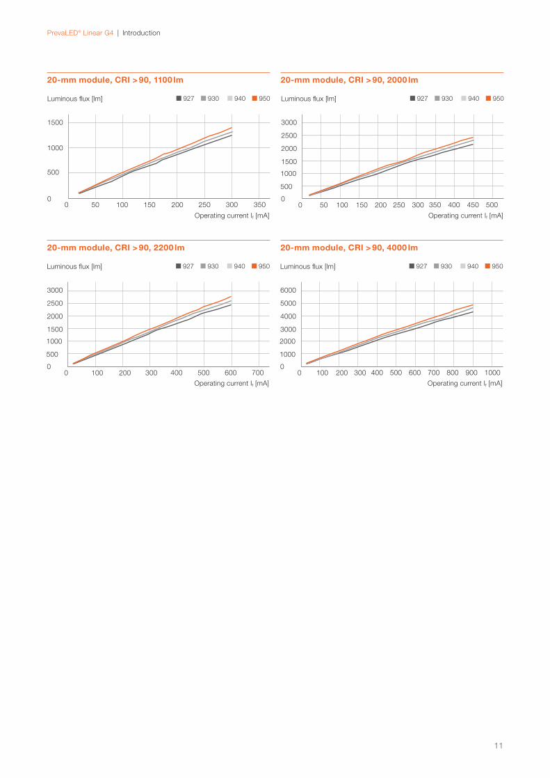
1.6 Luminous fl ux as a function of forward current 09
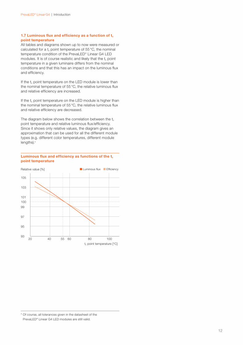
1.7 Luminous fl ux and effi ciency as a function of tc point temperature 12
2 Optical considerations 13
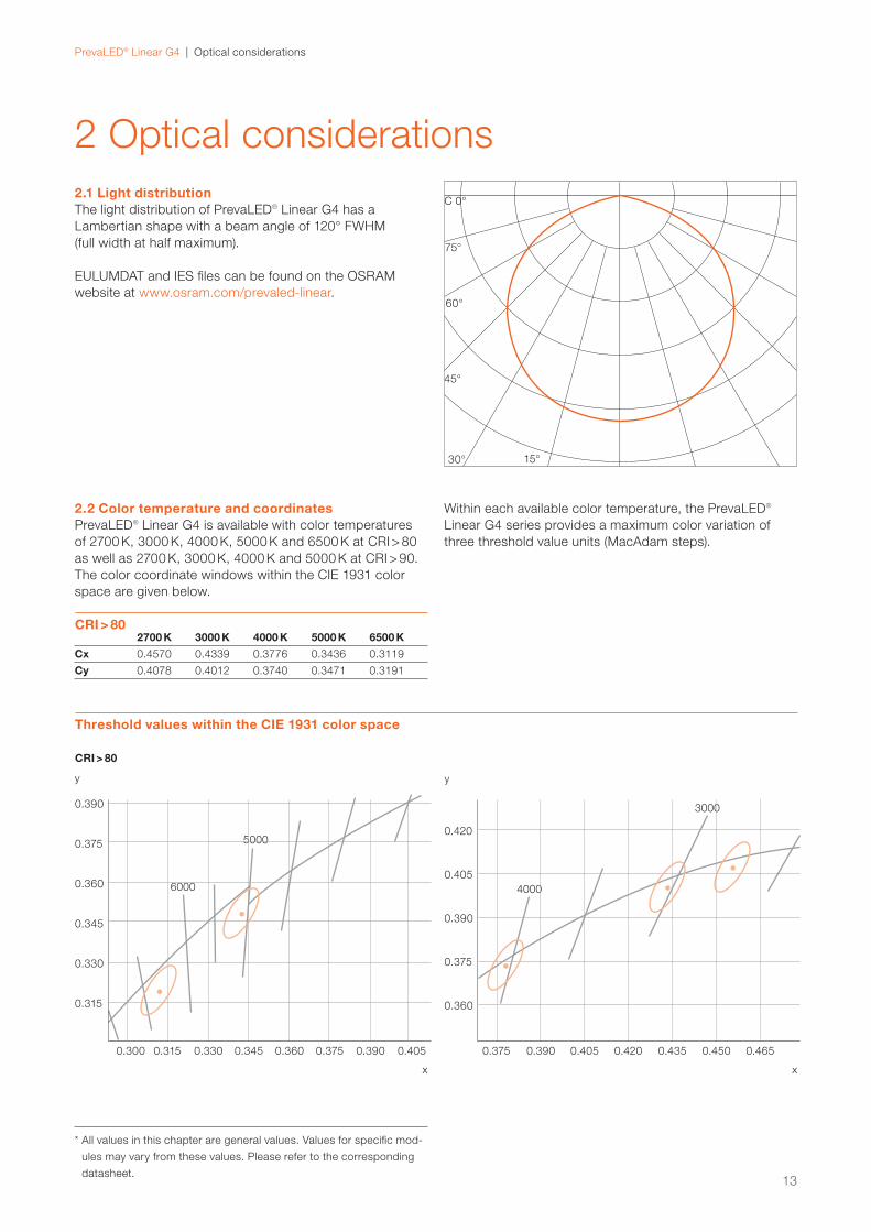
2.1 Light distribution 13
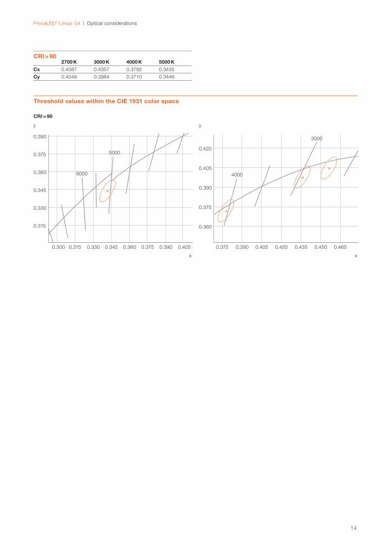
2.2 Color temperature and coordinates 13
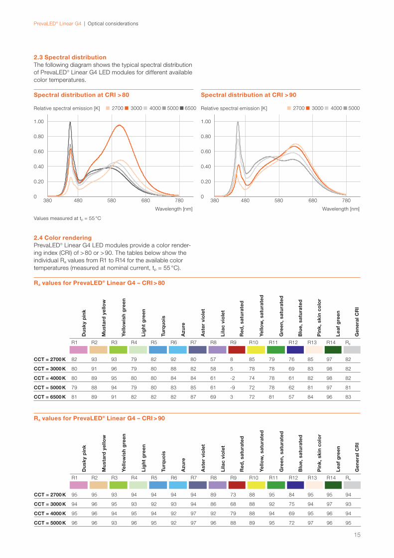
2.3 Spectral distribution 15
2.4 Color rendering 15
3 Electrical considerations 16
3.1 Wiring information 16
3.2 Disconnecting the wire from the connector 16
3.3 Electrostatic discharge (ESD) 16
3.4 Forward voltage as a function of forward current 17
4 LED systems: PrevaLED® Linear G4 and
OPTOTRONIC® LED drivers 19
4.1 LED module/driver combinations 19
4.2 Installation examples 21
4.3 System combination tables 24
5 Thermal considerations 28
5.1 Introduction and defi nitions 28
5.2 tc location and measurement 28
5.3 Forward voltage as a function of tc point temperature 29
6 Lifetime and lumen maintenance 30
7 Mechanical considerations 32
7.1 LED module dimensions 32
7.2 Number of LEDs, LED pitch 37
7.3 Mechanical protection 37
7.4 Mounting instructions 37
8 Safety information 38
Please note:All information in this guide has been prepared with great
care. OSRAM, however, does not accept liability for
possible errors, changes and/or omissions. Please check
www.osram.com or contact your sales partner for an
updated copy of this guide. This technical application guide
is for information purposes only and aims to support you in
tackling the challenges and taking full advantage of all
opportunities the technology has to offer. Please note that
this guide is based on own measurements, tests, specifi c
parameters and assumptions. Individual applications may
not be covered and need different handling. Responsibility
and testing obligations remain with the luminaire manu-
facturer/OEM/application planner.
PrevaLED® Linear G4 | Contents
PrevaLED® Linear G4 | Introduction
1 Introduction
1.2 System solutionOSRAM offers you the optimal combination of LED module
and LED driver. By combining OPTOTRONIC® Linear LED
drivers with PrevaLED® Linear G4 LED modules, you always
get the best possible system solution, which is perfectly
complemented by useful accessories and modern LMS
components for effi cient and multifunctional light management.
1.3 Features and benefi ts — Efficiency: Up to 200 lm/W
— Initial color consistency ≤ 3 SDCM
— CCT: 2700 K, 3000 K, 4000 K, 5000 K, 6500 K
— CRI: > 80, > 90
— Insulated connector with release function
— SELV/non-SELV LED module for easier luminaire design
— Average lifetime (L80B10): 50000 h at tc = 55 °C
with CRI > 80
— Average lifetime (L80B50): 50000 h at tc = 55 °C
with CRI > 90
— Geometry according to Zhaga book 7 L28W2, L56W2
and L28W4, L56W4
— CE, ENEC conformity and VDE certifi cation
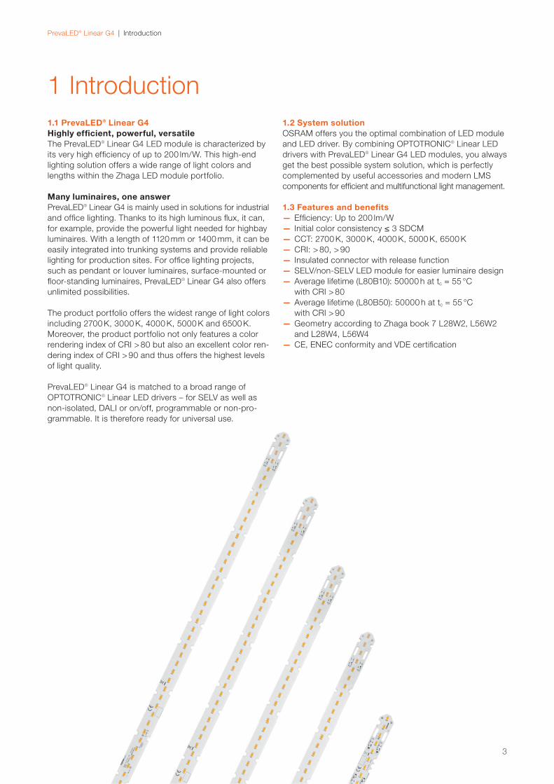
1.1 PrevaLED® Linear G4Highly effi cient, powerful, versatileThe PrevaLED® Linear G4 LED module is characterized by
its very high effi ciency of up to 200 lm/W. This high-end
lighting solution offers a wide range of light colors and
lengths within the Zhaga LED module portfolio.
Many luminaires, one answerPrevaLED® Linear G4 is mainly used in solutions for industrial
and offi ce lighting. Thanks to its high luminous fl ux, it can,
for example, provide the powerful light needed for highbay
luminaires. With a length of 1120 mm or 1400 mm, it can be
easily integrated into trunking systems and provide reliable
lighting for production sites. For offi ce lighting projects,
such as pendant or louver luminaires, surface-mounted or
fl oor-standing luminaires, PrevaLED® Linear G4 also offers
unlimited possibilities.
The product portfolio offers the widest range of light colors
including 2700 K, 3000 K, 4000 K, 5000 K and 6500 K.
Moreover, the product portfolio not only features a color
rendering index of CRI > 80 but also an excellent color ren-
dering index of CRI > 90 and thus offers the highest levels
of light quality.
PrevaLED® Linear G4 is matched to a broad range of
OPTOTRONIC® Linear LED drivers – for SELV as well as
non-isolated, DALI or on/off, programmable or non-pro-
grammable. It is therefore ready for universal use.
3
PrevaLED® Linear G4 | Introduction
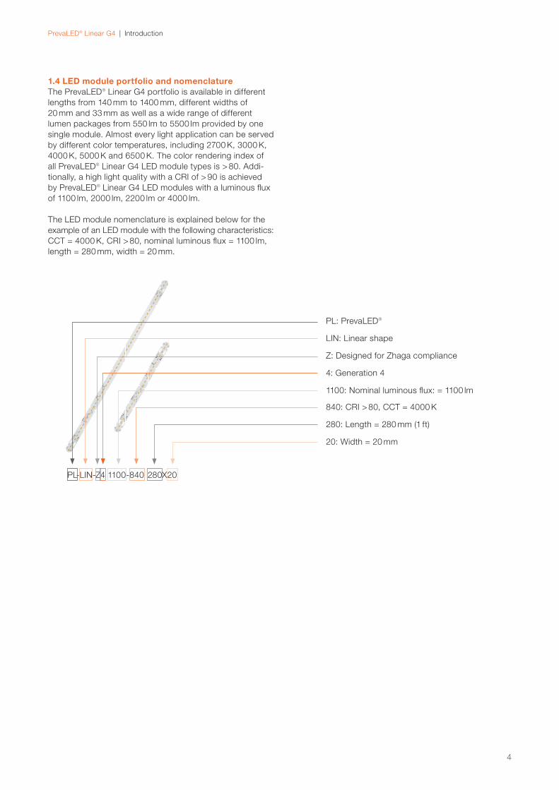
1.4 LED module portfolio and nomenclatureThe PrevaLED® Linear G4 portfolio is available in different
lengths from 140 mm to 1400 mm, different widths of
20 mm and 33 mm as well as a wide range of different
lumen packages from 550 lm to 5500 lm provided by one
single module. Almost every light application can be served
by different color temperatures, including 2700 K, 3000 K,
4000 K, 5000 K and 6500 K. The color rendering index of
all PrevaLED® Linear G4 LED module types is > 80. Addi-
tionally, a high light quality with a CRI of > 90 is achieved
by PrevaLED® Linear G4 LED modules with a luminous fl ux
of 1100 lm, 2000 lm, 2200 lm or 4000 lm.
The LED module nomenclature is explained below for the
example of an LED module with the following characteristics:
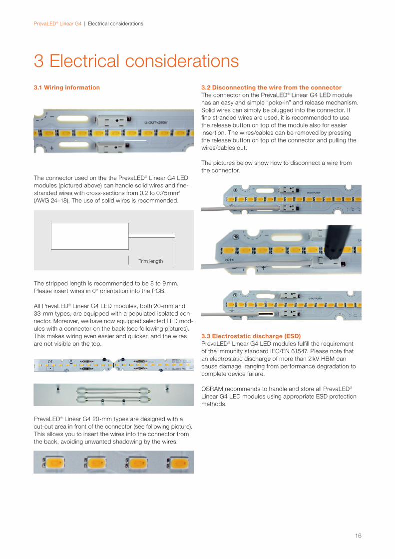
The connector used on the the PrevaLED® Linear G4 LED
modules (pictured above) can handle solid wires and fine-
stranded wires with cross-sections from 0.2 to 0.75 mm2
(AWG 24–18). The use of solid wires is recommended.
The stripped length is recommended to be 8 to 9 mm.
Please insert wires in 0° orientation into the PCB.
3.2 Disconnecting the wire from the connectorThe connector on the PrevaLED® Linear G4 LED module
has an easy and simple “poke-in” and release mechanism.
Solid wires can simply be plugged into the connector. If
fine stranded wires are used, it is recommended to use
the release button on top of the module also for easier
insertion. The wires/cables can be removed by pressing
the release button on top of the connector and pulling the
wires/cables out.
The pictures below show how to disconnect a wire from
the connector.
3.3 Electrostatic discharge (ESD)PrevaLED® Linear G4 LED modules fulfill the requirement
of the immunity standard IEC/EN 61547. Please note that
an electrostatic discharge of more than 2 kV HBM can
cause damage, ranging from performance degradation to
complete device failure.
OSRAM recommends to handle and store all PrevaLED®
Linear G4 LED modules using appropriate ESD protection
methods.
Trim length
All PrevaLED® Linear G4 LED modules, both 20-mm and
33-mm types, are equipped with a populated isolated con-
nector. Moreover, we have now equipped selected LED mod-
ules with a connector on the back (see following pictures).
This makes wiring even easier and quicker, and the wires
are not visible on the top.
PrevaLED® Linear G4 20-mm types are designed with a
cut-out area in front of the connector (see following picture).
This allows you to insert the wires into the connector from
the back, avoiding unwanted shadowing by the wires.
16
PrevaLED® Linear G4 | Electrical considerations
CRI > 80
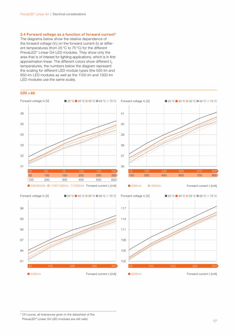
3.4 Forward voltage as a function of forward current*The diagrams below show the relative dependence of
the forward voltage (Vf) on the forward current (If) at differ-
ent temperatures (from 25 °C to 75 °C) for the different
PrevaLED® Linear G4 LED modules. They show only the
area that is of interest for lighting applications, which is in first
approximation linear. The different colors show different tp
temperatures, the numbers below the diagram represent
the scaling for different LED module types (the 550-lm and
650-lm LED modules as well as the 1100-lm and 1300-lm
LED modules use the same scale).
2000 lm 4000 lm Forward current If [mA]
22575 150 300 375 450
Forward voltage Vf [V]
36
37
38
39
40
41
25 °C 45 °C 55 °C 65 °C 75 °C
450150 300 600 750 900
5500 lm Forward current If [mA]
50 150 250 450350
Forward voltage Vf [V]
102
105
108
111
114
117
25 °C 45 °C 55 °C 65 °C 75 °C
* Of course, all tolerances given in the datasheet of the
PrevaLED® Linear G4 LED modules are still valid.
550/650 lm 1100/1300 lm 2200 lm Forward current If [mA]
7525 50 100 150125
Forward voltage Vf [V]
31
32
33
34
35
36
25 °C 45 °C 55 °C 65 °C 75 °C
300100 200 400 600500
15050 100 200 300250
4400 lm Forward current If [mA]
50 150 250 450350
Forward voltage Vf [V]
81
84
87
90
93
96
25 °C 45 °C 55 °C 65 °C 75 °C
17
18
PrevaLED® Linear G4 | Electrical considerations
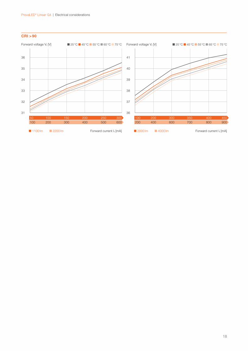
CRI > 90
2000 lm 4000 lm Forward current If [mA]
300100 200 350 400 450
Forward voltage Vf [V]
36
37
38
39
40
41
25 °C 45 °C 55 °C 65 °C 75 °C
600200 400 700 800 900
1100 lm 2200 lm Forward current If [mA]
15050 100 200 250 300
Forward voltage Vf [V]
31
32
33
34
35
36
25 °C 45 °C 55 °C 65 °C 75 °C
300100 200 400 500 600
PrevaLED® Linear G4 | LED systems: PrevaLED® Linear G4 and OPTOTRONIC® LED drivers
4 LED systems: PrevaLED® Linear G4
and OPTOTRONIC® LED drivers
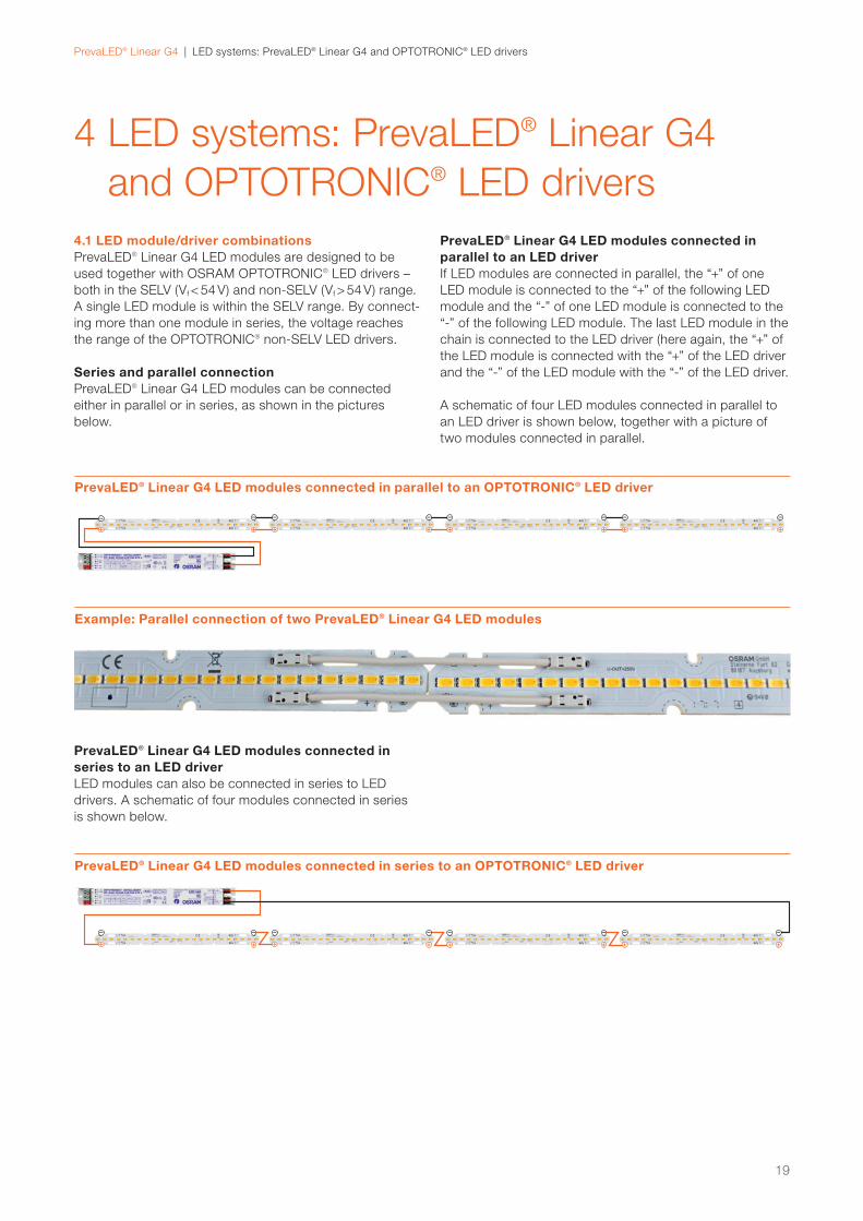
4.1 LED module/driver combinationsPrevaLED® Linear G4 LED modules are designed to be
used together with OSRAM OPTOTRONIC® LED drivers –
both in the SELV (Vf < 54 V) and non-SELV (Vf > 54 V) range.
A single LED module is within the SELV range. By connect-
ing more than one module in series, the voltage reaches
the range of the OPTOTRONIC® non-SELV LED drivers.
Series and parallel connectionPrevaLED® Linear G4 LED modules can be connected
either in parallel or in series, as shown in the pictures
below.
PrevaLED® Linear G4 LED modules connected inparallel to an LED driverIf LED modules are connected in parallel, the “+” of one
LED module is connected to the “+” of the following LED
module and the “-” of one LED module is connected to the
“-” of the following LED module. The last LED module in the
chain is connected to the LED driver (here again, the “+” of
the LED module is connected with the “+” of the LED driver
and the “-” of the LED module with the “-” of the LED driver.
A schematic of four LED modules connected in parallel to
an LED driver is shown below, together with a picture of
two modules connected in parallel.
PrevaLED® Linear G4 LED modules connected inseries to an LED driverLED modules can also be connected in series to LED
drivers. A schematic of four modules connected in series
is shown below.
PrevaLED® Linear G4 LED modules connected in parallel to an OPTOTRONIC® LED driver
PrevaLED® Linear G4 LED modules connected in series to an OPTOTRONIC® LED driver
Example: Parallel connection of two PrevaLED® Linear G4 LED modules
19
PrevaLED® Linear G4 | LED systems: PrevaLED® Linear G4 and OPTOTRONIC® LED drivers
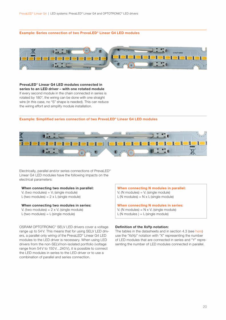
Example: Series connection of two PrevaLED® Linear G4 LED modules
Example: Simplified series connection of two PrevaLED® Linear G4 LED modules
PrevaLED® Linear G4 LED modules connected inseries to an LED driver – with one rotated moduleIf every second module in the chain connected in series is
rotated by 180°, the wiring can be done with one straight
wire (in this case, no “S” shape is needed). This can reduce
the wiring effort and simplify module installation.
Electrically, parallel and/or series connections of PrevaLED®
Linear G4 LED modules have the following impacts on the
electrical parameters:
When connecting two modules in parallel:Vf (two modules) = Vf (single module)
If (two modules) = 2 x If (single module)
When connecting two modules in series:Vf (two modules) = 2 x Vf (single module)
If (two modules) = If (single module)
When connecting N modules in parallel:Vf (N modules) = Vf (single module)
If (N modules) = N x If (single module)
When connecting N modules in series:Vf (N modules) = N x Vf (single module)
If (N modules ) = If (single module)
OSRAM OPTOTRONIC® SELV LED drivers cover a voltage
range up to 54 V. This means that for using SELV LED driv-
ers, a parallel-only wiring of the PrevaLED® Linear G4 LED
modules to the LED driver is necessary. When using LED
drivers from the non-SELV/non-isolated portfolio (voltage
range from 54 V to 150 V…240 V), it is possible to connect
the LED modules in series to the LED driver or to use a
combination of parallel and series connection.
Definition of the XsYp notation:The tables in the datasheets and in section 4.3 (see here)
use the “XsYp” notation with “X” representing the number
of LED modules that are connected in series and “Y” repre-
senting the number of LED modules connected in parallel.
20
21
PrevaLED® Linear G4 | LED systems: PrevaLED® Linear G4 and OPTOTRONIC® LED drivers
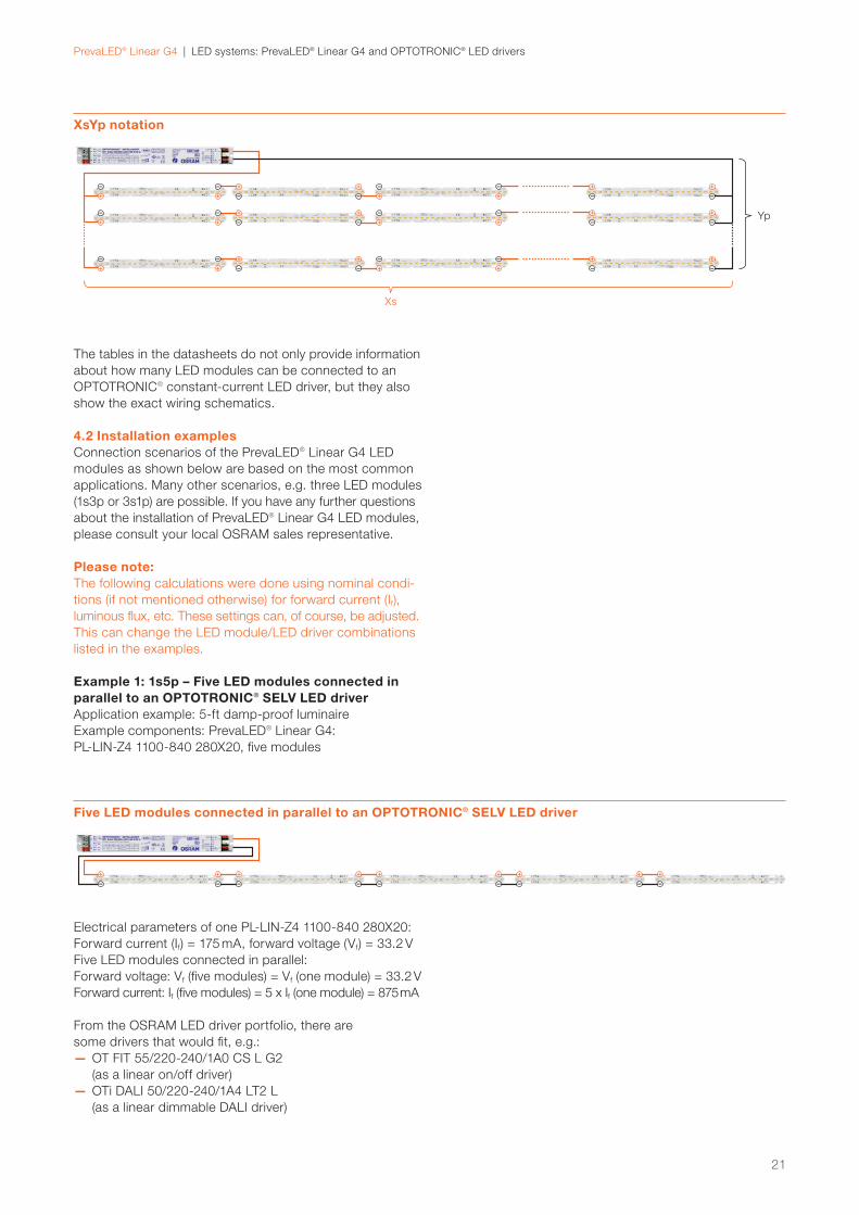
XsYp notation
Five LED modules connected in parallel to an OPTOTRONIC® SELV LED driver
The tables in the datasheets do not only provide information
about how many LED modules can be connected to an
OPTOTRONIC® constant-current LED driver, but they also
show the exact wiring schematics.
4.2 Installation examplesConnection scenarios of the PrevaLED® Linear G4 LED
modules as shown below are based on the most common
applications. Many other scenarios, e.g. three LED modules
(1s3p or 3s1p) are possible. If you have any further questions
about the installation of PrevaLED® Linear G4 LED modules,
please consult your local OSRAM sales representative.
Please note:The following calculations were done using nominal condi-
tions (if not mentioned otherwise) for forward current (If),
luminous flux, etc. These settings can, of course, be adjusted.
This can change the LED module/LED driver combinations
listed in the examples.
Example 1: 1s5p – Five LED modules connected in parallel to an OPTOTRONIC® SELV LED driver Application example: 5-ft damp-proof luminaire
Example components: PrevaLED® Linear G4:
PL-LIN-Z4 1100-840 280X20, five modules
Electrical parameters of one PL-LIN-Z4 1100-840 280X20:
Forward current (If) = 175 mA, forward voltage (Vf) = 33.2 V
Forward current: If (five modules) = 5 x If (one module) = 875 mA
From the OSRAM LED driver portfolio, there are
some drivers that would fit, e.g.:
— OT FIT 55/220-240/1A0 CS L G2
(as a linear on/off driver)
— OTi DALI 50/220-240/1A4 LT2 L
(as a linear dimmable DALI driver)
Xs
Yp
22
PrevaLED® Linear G4 | LED systems: PrevaLED® Linear G4 and OPTOTRONIC® LED drivers
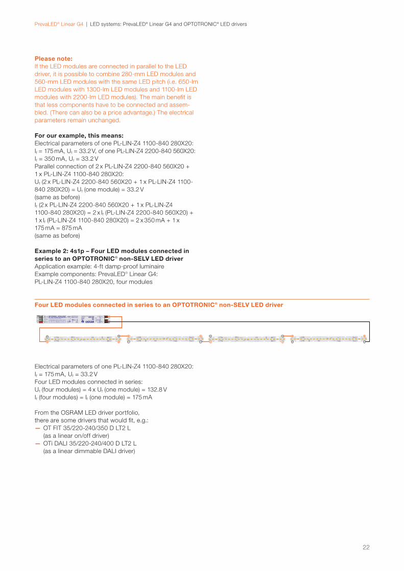
Please note:If the LED modules are connected in parallel to the LED
driver, it is possible to combine 280-mm LED modules and
560-mm LED modules with the same LED pitch (i.e. 650-lm
LED modules with 1300-lm LED modules and 1100-lm LED
modules with 2200-lm LED modules). The main benefit is
that less components have to be connected and assem-
bled. (There can also be a price advantage.) The electrical
parameters remain unchanged.
For our example, this means:Electrical parameters of one PL-LIN-Z4 1100-840 280X20:
If = 175 mA, Uf = 33.2 V, of one PL-LIN-Z4 2200-840 560X20:
If = 350 mA, Uf = 33.2 V
Parallel connection of 2 x PL-LIN-Z4 2200-840 560X20 +
1 x PL-LIN-Z4 1100-840 280X20:
Uf (2 x PL-LIN-Z4 2200-840 560X20 + 1 x PL-LIN-Z4 1100-
840 280X20) = Uf (one module) = 33.2 V
(same as before)
If (2 x PL-LIN-Z4 2200-840 560X20 + 1 x PL-LIN-Z4
1100-840 280X20) = 2 x If (PL-LIN-Z4 2200-840 560X20) +
1 x If (PL-LIN-Z4 1100-840 280X20) = 2 x 350 mA + 1 x
175 mA = 875 mA
(same as before)
Example 2: 4s1p – Four LED modules connected in series to an OPTOTRONIC® non-SELV LED driver Application example: 4-ft damp-proof luminaire
Example components: PrevaLED® Linear G4:
PL-LIN-Z4 1100-840 280X20, four modules
Four LED modules connected in series to an OPTOTRONIC® non-SELV LED driver
Electrical parameters of one PL-LIN-Z4 1100-840 280X20:
If = 175 mA, Uf = 33.2 V
Four LED modules connected in series:
Uf (four modules) = 4 x Uf (one module) = 132.8 V
If (four modules) = If (one module) = 175 mA
From the OSRAM LED driver portfolio,
there are some drivers that would fit, e.g.:
— OT FIT 35/220-240/350 D LT2 L
(as a linear on/off driver)
— OTi DALI 35/220-240/400 D LT2 L
(as a linear dimmable DALI driver)
23
PrevaLED® Linear G4 | LED systems: PrevaLED® Linear G4 and OPTOTRONIC® LED drivers
Example 3: 2s4p – Four strings of two LED modules, each connected in parallel to an OPTOTRONIC® non-SELV LED driverApplication example: 2' x 2' troffer luminaire
Example components: PrevaLED® Linear G4:
PL-LIN-Z4 1100-840 280X20, eight modules
Electrical parameters of one PL-LIN-Z4 1100-840 280X20:
If = 175 mA, Uf = 33.2 V
Two modules connected in series: Uf (two modules) = 2 x Uf (one module) = 66.4 V
If (two modules) = If (one module) = 175 mA
Two modules connected four times in parallel:Uf (eight modules) = Uf (two modules) = 66.4 V
If (eight modules) = 4 x If (two modules) = 700 mA
From the OSRAM LED driver portfolio,
there are some drivers that would fi t, e.g.:
— OTi DALI 90/220-240/1A0 D LT2 L
(as a linear dimmable DALI driver)
Four strings of two LED modules, each connected in parallel to an OPTOTRONIC® non-SELV LED driver
PrevaLED® Linear G4 | LED systems: PrevaLED® Linear G4 and OPTOTRONIC® LED drivers
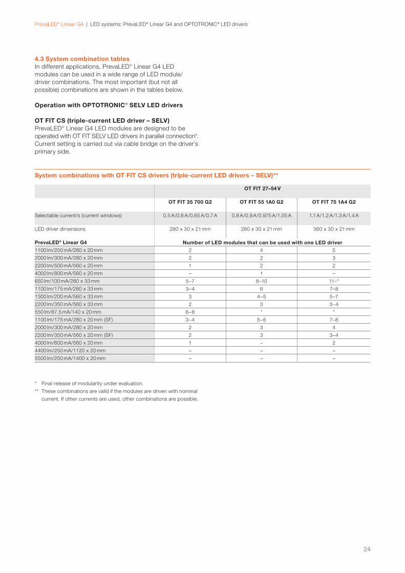
4.3 System combination tablesIn different applications, PrevaLED® Linear G4 LED
modules can be used in a wide range of LED module/
driver combinations. The most important (but not all
possible) combinations are shown in the tables below.
Operation with OPTOTRONIC® SELV LED drivers
OT FIT CS (triple-current LED driver – SELV) PrevaLED® Linear G4 LED modules are designed to be
operated with OT FIT SELV LED drivers in parallel connection*.
Current setting is carried out via cable bridge on the driver’s
primary side.
System combinations with OT FIT CS drivers (triple-current LED drivers – SELV)**
OT FIT 27–54 V
OT FIT 35 700 G2 OT FIT 55 1A0 G2 OT FIT 75 1A4 G2
Selectable current/s (current windows) 0.5 A/0.6 A/0.65 A/0.7 A 0.8 A/0.9 A/0.975 A/1.05 A 1.1 A/1.2 A/1.3 A/1.4 A
LED driver dimensions 280 x 30 x 21 mm 280 x 30 x 21 mm 360 x 30 x 21 mm
PrevaLED® Linear G4 Number of LED modules that can be used with one LED driver 1100 lm/250 mA/280 x 20 mm 2 4 5
2000 lm/300 mA/280 x 20 mm 2 2 3
2200 lm/500 mA/560 x 20 mm 1 2 2
4000 lm/800 mA/560 x 20 mm – 1 –
650 lm/100 mA/280 x 33 mm 5–7 8–10 11–*
1100 lm/175 mA/280 x 33 mm 3–4 6 7–8
1300 lm/200 mA/560 x 33 mm 3 4–5 5–7
2200 lm/350 mA/560 x 33 mm 2 3 3–4
550 lm/87.5 mA/140 x 20 mm 6–8 * *
1100 lm/175 mA/280 x 20 mm (SF) 3–4 5–6 7–8
2000 lm/300 mA/280 x 20 mm 2 3 4
2200 lm/350 mA/560 x 20 mm (SF) 2 3 3–4
4000 lm/600 mA/560 x 20 mm 1 – 2
4400 lm/250 mA/1120 x 20 mm – – –
5500 lm/250 mA/1400 x 20 mm – – –
* Final release of modularity under evaluation.
** These combinations are valid if the modules are driven with nominal
current. If other currents are used, other combinations are possible.
24
PrevaLED® Linear G4 | LED systems: PrevaLED® Linear G4 and OPTOTRONIC® LED drivers
System combinations with OTi DALI drivers (wide-current-window LED drivers – SELV)***
OTi DALI 27–54 V
OTi DALI 35 700 OTi DALI 50 1A4 OTi DALI 80 2A1 OTi DALI 80 2A1
Selectable current/s (current windows) 0.2–0.7 A 0.6–1.4 A 1.0–2.1 A 1.0 –2.1 A
LED driver dimensions 360 x 30 x 21 mm 360 x 30 x 21 mm 423 x 30 x 21 mm 423 x 30 x 21 mm
PrevaLED® Linear G4 Number of LED modules that can be used with one LED driver 1100 lm/250 mA/280 x 20 mm 1–2 3–5 3–6 4–8
2000 lm/300 mA/280 x 20 mm 1 2–4 2–5 4–7
2200 lm/500 mA/560 x 20 mm 1 2 2–3 2–4
4000 lm/800 mA/560 x 20 mm – 1 1 2
650 lm/100 mA/280 x 33 mm 2–7 6–14 6–15 10–21
1100 lm/175 mA/280 x 33 mm 2–4 4–8 4–8 6–12
1300 lm/200 mA/560 x 33 mm 1–3 3–7 3–7 5–10
2200 lm/350 mA/560 x 33 mm 1–2 2–4 2–4 3–6
550 lm/87.5 mA/140 x 20 mm 3–8 7–* 7–* 11–24
1100 lm/175 mA/280 x 20 mm (SF) 2–4 4–8 4–8 5–12
2000 lm/300 mA/280 x 20 mm 1–2 2–4 2–5 4–7
2200 lm/350 mA/560 x 20 mm (SF) 1–2 2–4 2–4 3–6
4000 lm/600 mA/560 x 20 mm 1 1–2 1–2 2–3
4400 lm/250 mA/1120 x 20 mm – – – –
5500 lm/250 mA/1400 x 20 mm – – – –
OTi DALI (wide-current-window LED driver – SELV) PrevaLED® Linear G4 LED modules are designed to be
operated with OTi DALI LED drivers in parallel connection.*
Current setting is carried out via Tuner4TRONIC® software
and DALI magic.**
* Final release of modularity under evaluation.
** Current setting via LEDset2 not supported by this version of
PrevaLED® Linear G4.
*** These combinations are valid if the modules are driven with nominal
current. If other currents are used, other combinations are possible.
25
PrevaLED® Linear G4 | LED systems: PrevaLED® Linear G4 and OPTOTRONIC® LED drivers
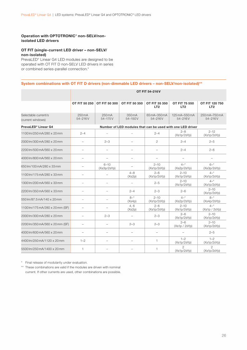
System combinations with OT FIT D drivers (non-dimmable LED drivers – non-SELV/non-isolated)**
OT FIT 54–216 V
OT FIT 50 250 OT FIT 50 300 OT FIT 50 350 OT FIT 35 350 LT2
OT FIT 75 550 LT2
OT FIT 120 750 LT2
Selectable current/s
(current windows)
250 mA54–216 V
250 mA54–175 V
350 mA54–150 V
65 mA–350 mA54–216 V
125 mA–550 mA54–216 V
250 mA–750 mA54–216 V
PrevaLED® Linear G4 Number of LED modules that can be used with one LED driver
1100 lm/250 mA/280 x 20 mm 2–4 – – 2–42–8
(Xs1p/2sYp)2–12
(Xs1p/2sYp)
2000 lm/300 mA/280 x 20 mm – 2–3 – 2 2–4 2–5
2200 lm/500 mA/560 x 20 mm – – – – 2–4 2–6
4000 lm/800 mA/560 x 20 mm – – – – – –
650 lm/100 mA/280 x 33 mm –6–10
(Xs3p/2sYp)–
2–10(Xs1p/2sYp)
4–*(Xs2p/2sYp)
6–*(Xs3p/2sYp)
1100 lm/175 mA/280 x 33 mm – –4–8
(Xs2p)2–6
(Xs1p/2sYp)2–10
(Xs1p/2sYp)4–*
(Xs1p/2sYp)
1300 lm/200 mA/560 x 33 mm – – – 2–52–10
(Xs1p/2sYp)4–*
(Xs1p/2sYp)
2200 lm/350 mA/560 x 33 mm – – 2–4 2–3 2–62–10
(Xs1p/2sYp)
550 lm/87.5 mA/140 x 20 mm – –8–*
(Xs4p)2–10
(Xs1p/2sYp)4–*
(Xs2p/2sYp)8–*
(Xs4p/2sYp)
1100 lm/175 mA/280 x 20 mm (SF) – –4, 6
(Xs2p)2–6
(Xs1p/2sYp)2–10
(Xs1p/2sYp)4–*
(Xs1p / 2sYp)
2000 lm/300 mA/280 x 20 mm – 2–3 – 2–32–6
(Xs1p/2sYp)2–10
(Xs1p/2sYp)
2200 lm/350 mA/560 x 20 mm (SF) – – 2–3 2–32–6
(Xs1p / 2sYp)2–10
(Xs1p/2sYp)
4000 lm/600 mA/560 x 20 mm – – – – – 2–5
4400 lm/250 mA/1120 x 20 mm 1–2 – – 11–2
(Xs1p/2sYp)1–2
(Xs1p/2sYp)
5500 lm/250 mA/1400 x 20 mm 1 – – 12
(Xs1p/2sYp)2
(Xs1p/2sYp)
Operation with OPTOTRONIC® non-SELV/non-isolated LED drivers
OT FIT (single-current LED driver – non-SELV/non-isolated)PrevaLED® Linear G4 LED modules are designed to be
operated with OT FIT D non-SELV LED drivers in series
or combined series-parallel connection.*
* Final release of modularity under evaluation.
** These combinations are valid if the modules are driven with nominal
current. If other currents are used, other combinations are possible.
26
PrevaLED® Linear G4 | LED systems: PrevaLED® Linear G4 and OPTOTRONIC® LED drivers
OTi (wide-current-window LED driver – non-SELV/non-isolated)PrevaLED® Linear G4 LED modules are designed to be
operated with OTi and OTi DALI LED drivers in series or
combined series-parallel connection.* Current setting is
carried out via resistor coding (LEDset) and for OTi DALI
LED drivers also via Tuner4TRONIC® software and DALI
magic.
System combinations with OTi (DALI) drivers (wide-current-window LED drivers – non-SELV/non-isolated)**
OTi DALI 54–240 V
OTi DALI 35 400 UF
OTi DALI 75 700 UF
OTi DALI 35 400 G3
OTi DALI 60 550 G3
OTi DALI 90 700 G3
OTi DALI 90 1A0 G3
OTi 60 550 OTi 90 1A0
Selectable current/s
(current windows)
75–400 mA
250– 700 mA
75–400 mA
125– 550 mA
250– 700 mA
250– 1000 mA
120– 550 mA
250–1000 mA
LED driver dimensions 360 x 30 x 11 mm
360 x 30 x 11 mm
280 x 30 x 21 mm
280 x 30 x 21 mm
280 x 30 x 21 mm
280 x 30 x 21 mm
280 x 30 x 21 mm
280 x 30 x 21 mm
PrevaLED® Linear G4 Number of LED modules that can be used with one LED driver
1100 lm/250 mA/280 x 20 mm 2–42–6
(Xs1p/2sYp)2–4
2–6 (Xs1p/2sYp)
2–10 (Xs1p/2sYp)
2–10 (Xs1p/2sYp)
2–6(Xs1p/2sYp)
2–10 (Xs1p/2sYp
2000 lm/300 mA/280 x 20 mm 22–4
(Xs1p/2sYp) 2 2–3 2–5 2–5 2–3 2–5
2200 lm/500 mA/560 x 20 mm – 2–4 – 2–3 2–5 2–5 2–3 2–5
4000 lm/800 mA/560 x 20 mm – – – – – 2 – 2
650 lm/100 mA/280 x 33 mm2–10
(Xs1p/2sYp)6–*
(Xs3p/2sYp)2–10
(Xs1p/2sYp)4–14
(Xs2p/2sYp)6–*
(Xs3p/2sYp)6–*
(Xs3p/2sYp)4–14
(Xs2p/2sYp)6–24
(Xs3p/2sYp)
1100 lm/175 mA/280 x 33 mm2–6
(Xs1p/2sYp)4–10
(Xs2p/2sYp)2–6
(Xs1p/2sYp)2–10
(Xs1p/2sYp)4–10
(Xs2p/2sYp)4–10
(Xs2p/2sYp)2–10
(Xs1p/2sYp)4–14
(Xs2p/2sYp)
1300 lm/200 mA/560 x 33 mm 2–54–10
(Xs2p/2sYp)2–5
2–8 (Xs1p/2sYp)
4–10 (Xs2p/2sYp)
4–10(Xs2p/2sYp)
2–8(Xs1p/2sYp)
4–12(Xs2p/2sYp)
2200 lm/350 mA/560 x 33 mm 2–32–6
(2Xs1p/2sYp)2–3 2–5
2–7 (Xs1p/2sYp)
2–7(Xs1p/2sYp)
2–52–6
(Xs1p/2sYp)
550 lm/87.5 mA/140 x 20 mm2–8
(Xs1p/2sYp)6–*
(Xs3p/2sYp)2–10
(Xs1p/2sYp)4–*
(Xs2p/2sYp)6–*
(Xs3p/2sYp)6–*
(Xs3p/2sYp)4–*
(Xs2p/2sYp)6–*
(Xs3p/2sYp)
1100 lm/175 mA/280 x 20 mm (SF)2–4
(Xs1p/2sYp)4–10
(Xs2p/2sYp)2–4
(Xs1p/2sYp)2–10
(Xs1p/2sYp)4–*
(Xs2p/2sYp)4–*
(Xs2p/2sYp)2–10
(Xs1p/2sYp)4–*
(Xs2p/2sYp)
2000 lm/300 mA/280 x 20 mm 2–32–6
(Xs1p/2sYp)2–3 2–5
2–6 (Xs1p/2sYp)
2–6(Xs1p/2sYp)
2–52–6
(Xs1p/2sYp)
2200 lm/350 mA/560 x 20 mm (SF) 2–32–6
(Xs1p/2sYp)2–3 2–5
2–7 (Xs1p/2sYp)
2–7(Xs1p/2sYp)
2–52–7
(Xs1p/2sYp)
4000 lm/600 mA/560 x 20 mm – 2–3 – – 2–3 2–3 – 2–3
4400 lm/250 mA/1120 x 20 mm 1 1–2 1 21–2
(Xs1p/2sYp)1–2
(Xs1p/2sYp)1–2 1–4
5500 lm/250 mA/1400 x 20 mm 1 1–2 1 11–2
(Xs1p/2sYp)1–2
(Xs1p/2sYp)1–2 1–3
* Final release of modularity under evaluation.
** These combinations are valid if the modules are driven with nominal
current. If other currents are used, other combinations are possible.
27
PrevaLED® Linear G4 | Thermal considerations
5 Thermal considerations
At nominal operating conditions, with the PrevaLED®
Linear G4 mounted onto or into a luminaire housing with
heat exchange to the environment, no special additional
heat sink is needed to avoid exceeding tc max = 75 °C.
To avoid overheating, it is nevertheless strongly recommended
to check the LED module temperature in any newly designed
luminaires.
It should also be mentioned here that lower tc point temper-
atures on the LED module increase the module’s efficiency.
Therefore, providing efficient cooling for the PrevaLED®
Linear G4 LED modules increases the system efficiency of
the luminaire/application.
5.1 Introduction and definitionsFor any LED module, including the PrevaLED® Linear G4
family, different temperatures (tp, tc, tc max etc.) are men-
tioned in the datasheet. They are sometimes confused,
therefore a short overview should be given at the beginning
of this chapter:
— tp is the performance temperature of the module.
That means that all the tables, diagrams and numbers
in the datasheet (and in this technical application guide)
refer to the performance temperature tp (if not men-
tioned otherwise).
— tc is the critical module temperature of the LED module.
Up to this temperature, one special feature can be guar-
anteed (e.g. the efficiency of the LED module at nominal
current is higher than 150 lm/W up to a temperature of
tc = 55 °C).
— tc max is the absolute maximum temperature up to
which the operation of the LED module is recommended.
All the temperatures mentioned above are measured at the
same point on the LED module, which is (mostly for histori-
cal reasons) called the “tc point” of the LED module. Its
position on the PrevaLED® Linear G4 LED modules is
shown below.
5.2 tc location and measurementProper thermal design of an LED luminaire is critical for
achieving best performance and ensuring long lifetime of all
components. To achieve a lifetime of 50000 hours (L80B10),
the sufficient heat exchange and thermal conduction be-
tween the light engine and the luminaire housing has to be
verified by measuring the temperature at the tc point.
The maximum temperature reached at the tc point must not
exceed 75 °C. This reference point for PrevaLED® Linear G4
is shown in the image below for the 1100-lm/280-mm LED
module type (for the other LED module types, the position
is similar).
Position of the tc measurement point on PrevaLED® Linear G4 LED modules
The easiest way to measure the temperature at the tc
point is by using a thermocouple. It is recommended to
use a thermocouple that can be glued onto the LED mod-
ule. Make sure that the thermocouple is fixed with direct
contact to the tc point.
tc measurement point
28
PrevaLED® Linear G4 | Thermal considerations
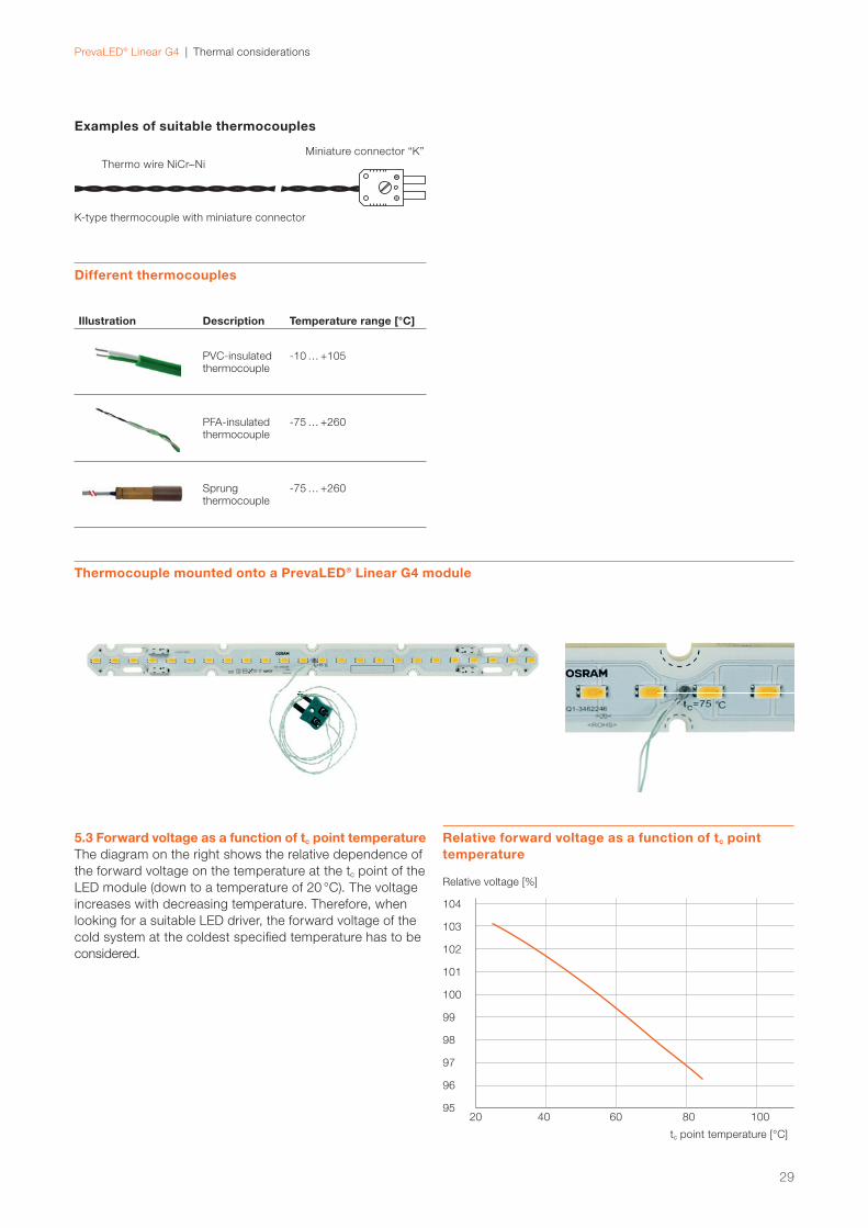
Examples of suitable thermocouples
Thermocouple mounted onto a PrevaLED® Linear G4 module
5.3 Forward voltage as a function of tc point temperatureThe diagram on the right shows the relative dependence of
the forward voltage on the temperature at the tc point of the
LED module (down to a temperature of 20 °C). The voltage
increases with decreasing temperature. Therefore, when
looking for a suitable LED driver, the forward voltage of the
cold system at the coldest specified temperature has to be
considered.
Different thermocouples
Illustration Description Temperature range [°C]
PVC-insulated thermo couple
-10 … +105
PFA-insulated thermo couple
-75 … +260
Sprung thermo couple
-75 … +260
K-type thermocouple with miniature connector
Miniature connector “K”
Thermo wire NiCr–Ni
Relative forward voltage as a function of tc point temperature
tc point temperature [°C]
Relative voltage [%]
95
96
102
101
100
99
103
97
98
104
80 10020 40 60
29
PrevaLED® Linear G4 | Lifetime and lumen maintenance
6 Lifetime and lumen maintenance
For the definition of the lifetime of an LED module, see
IEC/PAS 62717, where the following types are defined:
The luminous flux of an LED module decreases over its
lifespan. This decrease is specified by the L value. LXX
means that XX % of the initial light output is emitted by
the LED module (e.g. L70 = 70 %). The L value is always
connected to an operating time and defines the lifetime
of an LED module. Please be aware that the L value is a
statistical value. Therefore, the decrease in light output
can and will vary for different modules.
The B value specifies how many LED modules are below a
stated limit, e.g. B50 means that 50 % of the LED modules
are below a given L value.
The C value gives the number of fatal failures, meaning the
number of LED modules that are destroyed and do not emit
any light at all (e.g. C10 after 50000 hours means that after
50000 hours in operation, 10 % of the LED modules do not
emit any light).
The F value is the combination of the B and C value, mean-
ing that both fatal failures and degradation are considered.
Some examples: — L0C10 is the lifetime where the light output is 0 % for
10 % of the LED modules.
— L70B50 is the lifetime where the light output is ≥ 70 %
for 50 % of the LED modules. The B value includes only
gradual reduction of lumen output over time (not the
abrupt flux degradation).
— L70F50 is the lifetime where the light output is ≥ 70 %
for 50 % of the LED modules. The F value includes
reduction of lumen output over time including abrupt
degradation (flux = 0).
PrevaLED® Linear G4 LED CRI > 80 modules have a lifetime
of 50000 hours (L80B10) at a tc point temperature of 55 °C.
This means that after 50000 hours, a minimum of 90 % of
the utilized LED modules will maintain at least 80 % of the
initial luminous fl ux.
PrevaLED® Linear G4 LED CRI > 90 modules have a lifetime
of 50000 hours (L80B50) at a tc point temperature of 55 °C.
This means that after 50000 hours, a minimum of 50 % of
the utilized LED modules will maintain at least 80 % of the
initial luminous fl ux.
Please note: A higher tc temperature leads to a shorter lifetime of the
LED module. Moreover, the failure rate will also increase.
Average lifetime vs. tc at CRI > 80
tc temperature [°C]
Lifetime [h]
0
10000
20000
30000
40000
50000
60000
65 8525 35 45 55 75
L80B10
Average lifetime vs. tc at CRI > 90
tc temperature [°C]
Lifetime [h]
0
10000
20000
30000
40000
50000
60000
65 8525 35 45 55 75
L80B50
30
PrevaLED® Linear G4 | Lifetime and lumen maintenance
LxBy
x 70 80 90
y 10 50 10 50 10 50
[mA] Lifetime [h]
tp [°C] = 45
Irated/2 50000 50000 50000 50000 24000 32000
Irated 50000 50000 50000 50000 23000 30000
Imax 50000 50000 41000 50000 22000 28000
tp [°C] = 55
Irated/2 50000 50000 50000 50000 22000 28000
Irated 50000 50000 50000 50000 20000 27000
Imax 50000 50000 37000 50000 19000 25000
tp [°C] = 65
Irated/2 50000 50000 37000 50000 19000 25000
Irated 50000 50000 35000 47000 18000 24000
Imax 50000 50000 33000 45000 17000 23000
tp [°C] = 75
Irated/2 50000 50000 33000 45000 17000 23000
Irated 49000 50000 32000 43000 16000 21000
Imax 47000 50000 31000 41000 16000 20000
Lifetime data at CRI > 80
Lifetime data at CRI > 90
LxBy
x 70 80 90
y 10 50 10 50 10 50
[mA] Lifetime [h]
tp [°C] = 45
Irated/2 50000 50000 50000 50000 42000 48000
Irated 50000 50000 50000 50000 32000 36000
Imax 50000 50000 50000 50000 30000 33000
tp [°C] = 55
Irated/2 50000 50000 50000 50000 30000 33000
Irated 50000 50000 44000 50000 23000 26000
Imax 50000 50000 41000 47000 21000 24000
tp [°C] = 65
Irated/2 50000 50000 41000 47000 21000 24000
Irated 49000 50000 32000 36000 16000 19000
Imax 46000 50000 30000 34000 15000 17000
tp [°C] = 75
Irated/2 46000 50000 30000 34000 15000 17000
Irated 36000 41000 23000 26000 12000 14000
Imax 34000 39000 22000 25000 11000 13000
Illustration of the temperature-dependent lumen maintenance (B10) at current Inom and CRI > 80
Lifetime [h]
Lumen maintenance [L/L0]
0
1.2
0 20000 40000 60000 80000 100000
tp = 55 °C tp = 75 °C
1
0.8
0.6
0.4
0.2
120000
Illustration of the temperature-dependent lumen maintenance (B50) at current Inom and CRI > 90
Lifetime [h]
Lumen maintenance [L/L0]
0
1.2
0 20000 40000 60000 80000 100000
tp = 55 °C tp = 75 °C
1
0.8
0.6
0.4
0.2
120000
31
PrevaLED® Linear G4 | Mechanical considerations
7 Mechanical considerations
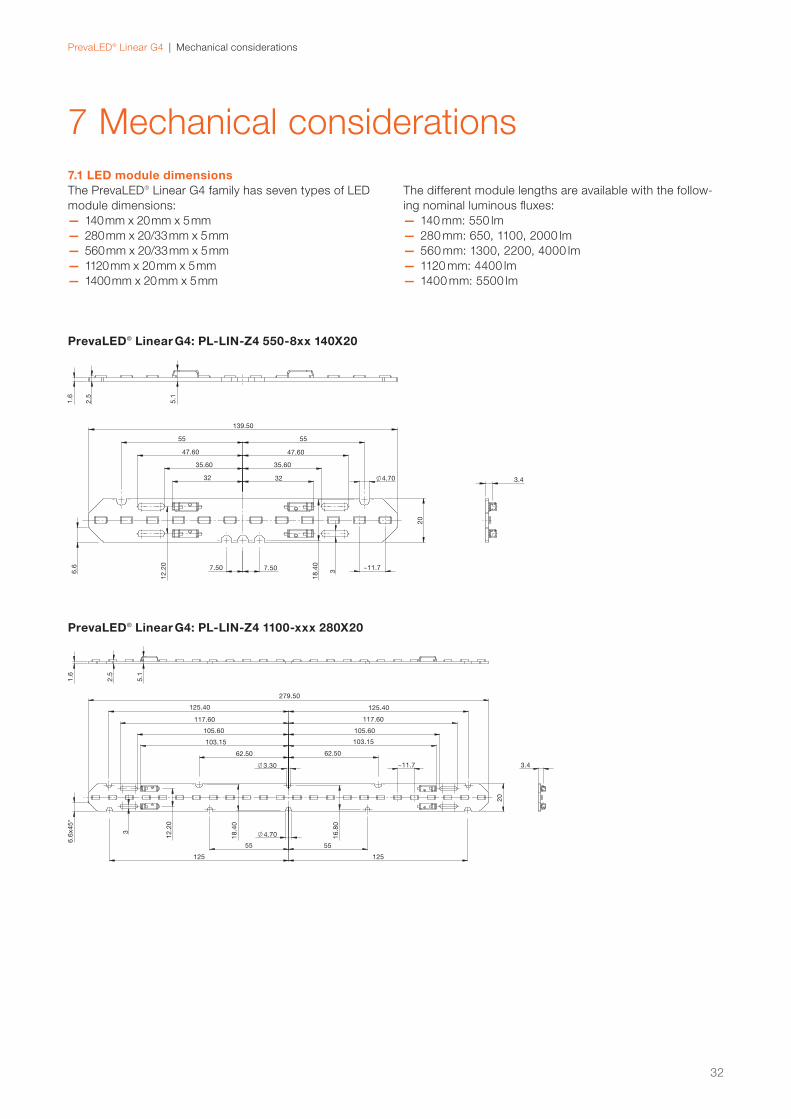
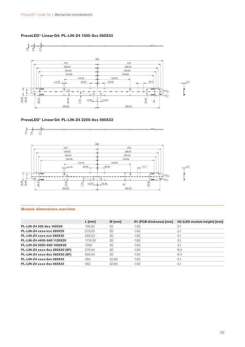
7.1 LED module dimensionsThe PrevaLED® Linear G4 family has seven types of LED
module dimensions:
— 140 mm x 20 mm x 5 mm
— 280 mm x 20/33 mm x 5 mm
— 560 mm x 20/33 mm x 5 mm
— 1120 mm x 20 mm x 5 mm
— 1400 mm x 20 mm x 5 mm
The different module lengths are available with the follow-
ing nominal luminous fl uxes:
— 140 mm: 550 lm
— 280 mm: 650, 1100, 2000 lm
— 560 mm: 1300, 2200, 4000 lm
— 1120 mm: 4400 lm
— 1400 mm: 5500 lm
PrevaLED® Linear G4: PL-LIN-Z4 550-8xx 140X20
PrevaLED® Linear G4: PL-LIN-Z4 1100-xxx 280X20
32
3.4
20
1.6
2.5
5.1
6.6
x4
5°
3
3.30 ~11.7
4.70 16
.80
18
.40
12
.20
279.50
125.40 125.40
117.60 117.60
105.60 105.60
103.15 103.15
62.50 62.50
5555
125125
1.6
2.5
5.1
5555
3.4
20
~11.7
3
18
.40
7.507.50
12
.20
6.6
4.7032 32
35.6035.60
47.60 47.60
139.50
33
PrevaLED® Linear G4 | Mechanical considerations
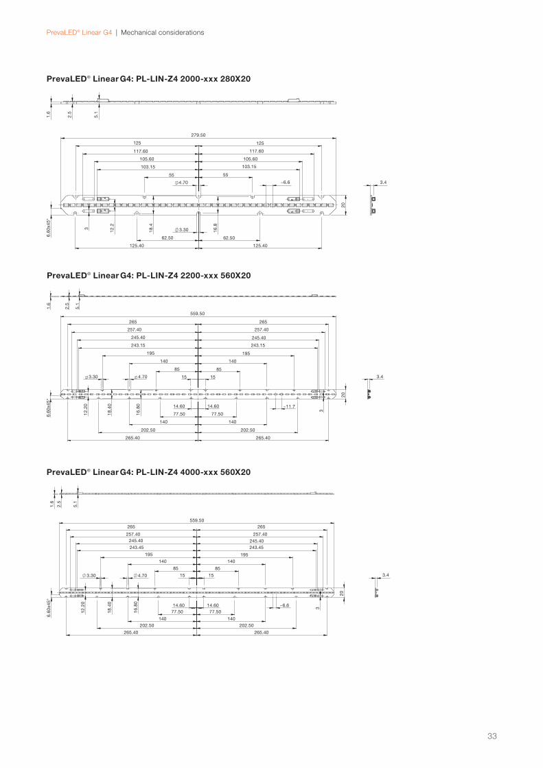
PrevaLED® Linear G4: PL-LIN-Z4 2200-xxx 560X20
PrevaLED® Linear G4: PL-LIN-Z4 4000-xxx 560X20
PrevaLED® Linear G4: PL-LIN-Z4 2000-xxx 280X20
1.6
2.5
559.50
265265
257.40257.40
195195
140140
8585
15 15 3.44.703.30
14.6014.60
77.50 77.50
140 140
202.50202.50
265.40 265.40
18
.40
16
.80
12
.20
20
6.6
0x4
5°
5.1
245.40 245.40
243.45243.45
~6.6
3
1.6
2.5
5.1
559.50
265265
257.40257.40
245.40 245.40
243.15243.15
195195
140140
8585
15 15 3.4
20
14.6014.60
77.50 77.50
140 140
202.50202.50
265.40 265.40
3
~11.7
16
.80
18
.40
12
.20
3.30 4.70
6.6
0x4
5°
3.4
20
1.6
2.5
5.1
6.6
0x4
5°
3 3.30
~6.64.70
16
.8
18
.4
12
.2
279.50
125 125
117.60 117.60
105.60 105.60
103.15 103.15
55 55
62.5062.50
125.40125.40
34
PrevaLED® Linear G4 | Mechanical considerations
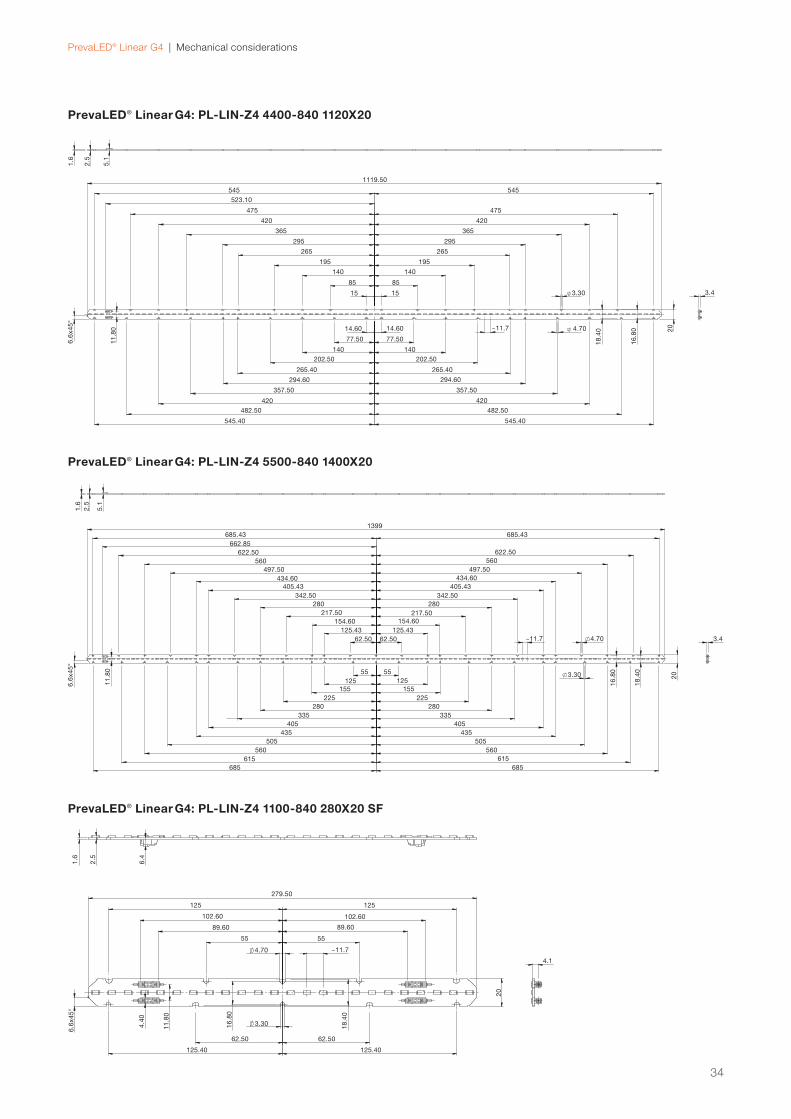
PrevaLED® Linear G4: PL-LIN-Z4 4400-840 1120X20
PrevaLED® Linear G4: PL-LIN-Z4 5500-840 1400X20
PrevaLED® Linear G4: PL-LIN-Z4 1100-840 280X20 SF
279.50
125125
102.60102.60
89.6089.60
5555
1.6
2.5
6.4
4.70 ~11.7
62.50 62.50
125.40125.40
3.304.4
0
11
.80
16
.80
18
.40
20
4.1
6.6
x4
5°
1.6
2.5
5.1
1399
685.43 685.43
622.50 622.50
662.85
560 560
497.50497.50
434.60434.60
405.43 405.43
342.50 342.50
280 280
3.4
20
217.50 217.50
154.60 154.60
125.43125.43
62.5062.50
685 685
615 615
560 560
505505
435435
405 405
335335
280280
225225
155 155
125 125
55 55
6.6
x4
5°
11
.80
~11.7 4.70
3.30
16
.80
18
.40
3.4
20
16
.80
18
.404.70
3.30
1.6
2.5
5.1
6.6
x4
5°
11
.80 ~11.7
1119.50
545 545
523.10
475 475
420420
365 365
295 295
265 265
195 195
140 140
85 85
15 15
14.6014.60
77.5077.50
140140
202.50 202.50
265.40265.40
294.60294.60
357.50357.50
420 420
482.50 482.50
545.40545.40
35
PrevaLED® Linear G4 | Mechanical considerations
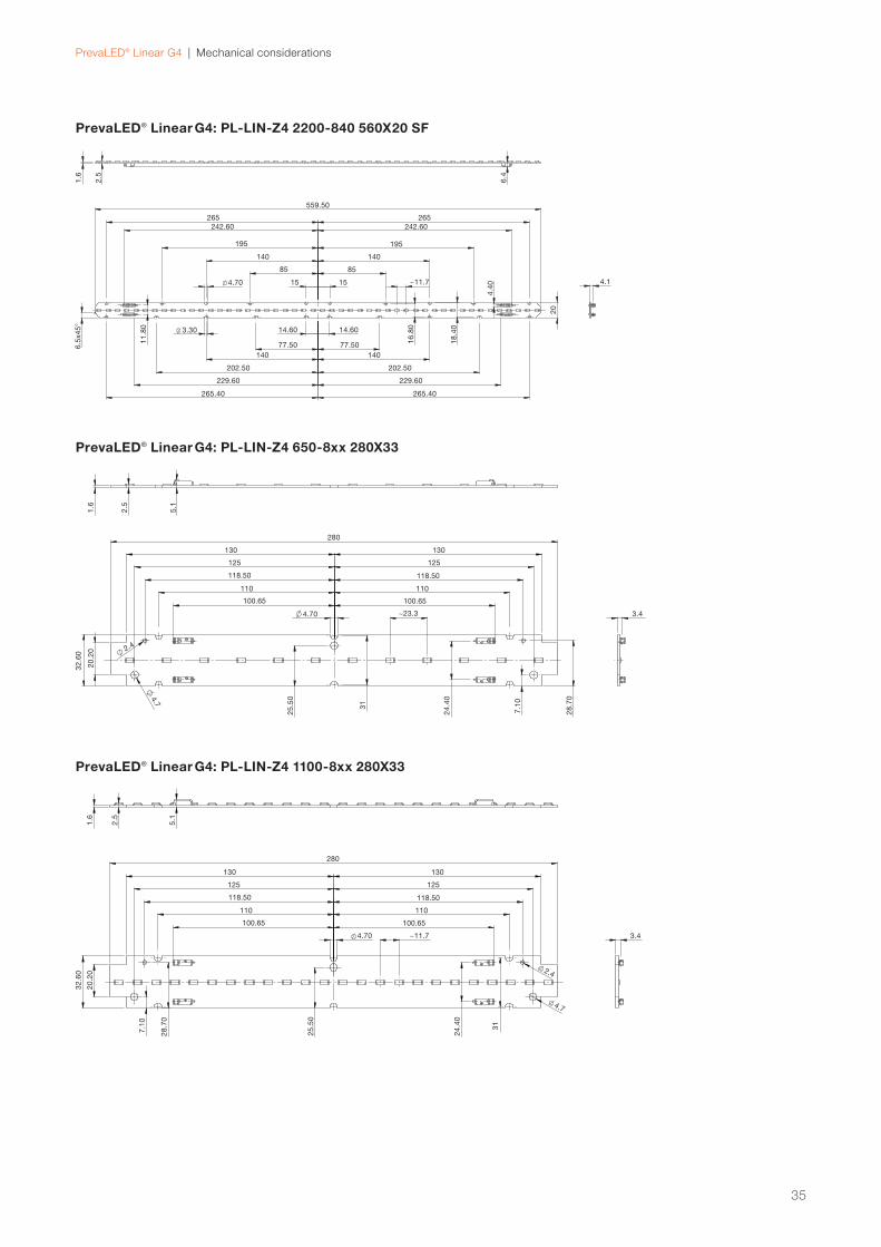
PrevaLED® Linear G4: PL-LIN-Z4 2200-840 560X20 SF
PrevaLED® Linear G4: PL-LIN-Z4 650-8xx 280X33
PrevaLED® Linear G4: PL-LIN-Z4 1100-8xx 280X33
280
130 130
125 125
118.50 118.50
110 110
100.65100.65
~11.74.70 3.4
2.4
4.7
1.6
2.5
5.1
7.1
0
28
.70
20
.20
32
.60
25
.50
24
.40
31
280
130 130
125 125
118.50 118.50
110 110
100.65100.65
3.4~23.34.70
31
24
.40
25
.504
.7
2.4
32
.60
20
.20
7.1
0
28
.70
1.6
2.5
5.1
1.6
2.5
6.4
559.50
265265
242.60242.60
195195
140140
8585
15 15 4.14.70 ~11.7
3.30 14.6014.60
77.50 77.50
140 140
202.50202.50
229.60229.60
265.40 265.40
18
.40
16
.80
4.4
0
11
.80
20
6.5
x4
5°
36
PrevaLED® Linear G4 | Mechanical considerations
PrevaLED® Linear G4: PL-LIN-Z4 1300-8xx 560X33
PrevaLED® Linear G4: PL-LIN-Z4 2200-8xx 560X33
Module dimensions overview
L [mm] W [mm] H1 (PCB thickness) [mm] H2 (LED module height) [mm]
PL-LIN-Z4 550-8xx 140X20 139.50 20 1.60 5.1
PL-LIN-Z4 xxxx-xxx 280X20 279.50 20 1.60 5.1
PL-LIN-Z4 xxxx-xxx 560X20 559.50 20 1.60 5.1
PL-LIN-Z4 4400-840 1120X20 1119.50 20 1.60 5.1
PL-LIN-Z4 5500-840 1400X20 1399 20 1.60 5.1
PL-LIN-Z4 xxxx-8xx 280X20 (SF) 279.50 20 1.60 6.4
PL-LIN-Z4 xxxx-8xx 560X20 (SF) 559.50 20 1.60 6.4
PL-LIN-Z4 xxxx-8xx 280X33 280 32.60 1.60 5.1
PL-LIN-Z4 xxxx-8xx 560X33 560 32.60 1.60 5.1
560
270 270
258.50 258.50
250.50 250.50
240.65240.65
140.50 140.50
30.5030.50 ~11.7
265.50 265.50
15.5015.50
3.4
2.4
4.7
32
.60
20
.20
28
.70
25
.50
7.1
0
31
24
.40
4.70
1.6
2.5
5.1
560
270 270
258.50 258.50
250.50 250.50
240.65240.65
140.50 140.50
1.6
2.5
5.1
30.5030.50 3.4
2.4
4.7
15.5015.50
24
.40
31
265.50265.50
7.1
0
25
.50
28
.70
20
.20
32
.60
4.70 ~23.3
PrevaLED® Linear G4 | Mechanical considerations
Possible screws
Cylinder head, torx drive M4 screw (ISO 4762)
Diameter 4.0 mm
Head diameter 7.0 mm
Head height 4.0 mm
Flat head, button headTorx drive, hex drive
M4 screw (ISO 7380)
Diameter 4.0 mm
Head diameter 7.5 mm
Head height 2.1 mm
Number of LEDs and LED pitch for the different modules in the PrevaLED® Linear G4 family
Product name Number of LEDs Pitch [mm]
PL-LIN-Z4 550-8xx 140X20 12 11.7
PL-LIN-Z4 1100-xxx 280X20 (SF) 24 11.7
PL-LIN-Z4 2000-xxx 280X20 42 6.6
PL-LIN-Z4 2200-xxx 560X20 (SF) 48 11.7
PL-LIN-Z4 4000-xxx 560X20 84 6.6
PL-LIN-Z4 4400-8xx 1120X20 96 11.7
PL-LIN-Z4 5500-8xx 1400X20 120 11.7
PL-LIN-Z4 650-8xx 280X33 12 23.3
PL-LIN-Z4 1100-8xx 280X33 24 11.7
PL-LIN-Z4 1300-8xx 560X33 24 23.3
PL-LIN-Z4 2200-8xx 560X33 48 11.7
7.3 Mechanical protectionFor operation in damp, wet or dusty environments, the user
has to make sure that an adequate ingress protection (IP)
is chosen. The LED module has to be protected by a suit-
able IP rating of the luminaire housing. Please consider
the luminaire standard IEC 60598 as well as the different
requirements.
7.4 Mounting instructionsPlease apply force only to the dedicated mounting posi-
tions. Strong mechanical stress can lead to irreversible
damage of the LED module. To fi x the module to the
fi xture, you can use M4 screws according to DIN 7984
or DIN EN ISO.
The maximum allowed screw head diameter without using
an isolating washer between the screw and the mounting
hole is 7.5 mm. With larger screw heads, the minimum
distance between the screw and other conductive parts
on the PrevaLED® Linear G4 LED module can be below the
limit for creepage distances.
The maximum torque that should be applied on the screws
depends on factors such as the screw type and the luminaire
material. It is also infl uenced by the usage of washers. In
most cases, a torque between 0.5 Nm and 1 Nm is enough
to fi x the LED module in the luminaire housing and will not
damage the module.
7.2 Number of LEDs, LED pitch
It is also possible to use clips instead of screws,
e.g. the push-to-fi x (P2F) connectors from BJB:
www.bjb.com.
To achieve optimal fi xation of the LED module and also
optimal thermal management, it is recommended to use
all mounting holes in the PrevaLED® Linear G4 LED mod-
ules. Nevertheless, it is possible to reduce the number of
screws, but in that case thermal behavior and mechanical
strength has to be verifi ed.
In any case, it is strongly recommended to perform
mechanical and thermal testing of the LED modules in
the luminaire.
37
PrevaLED® Linear G4 | Safety information
8 Safety information
DisclaimerAll information contained in this document has been
collected, analyzed and verifi ed with great care by OSRAM.
However, OSRAM is not responsible for the correctness
and completeness of the information contained in this
document and OSRAM cannot be made liable for any
damage that occurs in connection with the use of and/or
reliance on the content of this document. The information
contained in this document refl ects the current state of
knowledge on the date of issue.
— The LED module itself and all its components must not be
mechanically stressed.
The modules are intended for operation only with matching OPTOTRONIC®. To also ease the luminaire/installation approval, electronic
control gear for LEDs or LED modules should carry the
CE mark and be ENEC-certifi ed. In Europe, the declara-
tions of conformity must include the following standards:
CE: EC 61347-2-13, EN 55015, IEC 61547 and IEC
61000-3-2 – ENEC: 61347-2-13 and IEC/EN 62384.
Also check for the mark of an independent authorized
certifi cation institute.
Please see the relevant brochure for more detailed
information (see “Related and Further Information”).
— Installation of LED modules (with power supplies) needs to
be made with regard to all applicable electrical and safety
standards. Only qualifi ed personnel should be allowed to
perform installations.
— Pay attention to standard ESD precautions when installing
the module.
— Photobiological safety according to IEC 62471, risk
group RG1
— Max. voltage U-OUT = 250 V for operation on non-


![VDR G4[e] S-VDR G4[e] - interschalt.com · Modular and scalable design ... VDR G4[e] S-VDR G4[e] Worldwide Network ... VDR Requirements S-VDR G4[e] S-VDR Requirements Overview](https://static.documents.pub/doc/80x56/5af3f3967f8b9a95468d4730/vdr-g4e-s-vdr-g4e-and-scalable-design-vdr-g4e-s-vdr-g4e-worldwide.jpg)


