Abstract In this paper, a novel approximate method is proposed for the linearization of the Hoek-Brown (H-B) plastic potential function to circumvent some computational difficulties encountered in the analysis of underground openings in dilatant rock masses subject to non-hydrostatic in situ stresses. This is achieved by computing the equivalent Mohr-Coulomb (M-C) dilation parameter. The proposed method is validated by conducting elastoplastic and elastic-brittle-plastic plane strain finite element analysis of circular and non-circular openings in dilatant and non-dilatant rock masses subject to hydrostatic and non-hydrostatic in situ stresses. Displacements computed by using the H-B strength and dilation parameters are compared with those obtained by using the equivalent M-C parameters. The agreement in results is found to be very good. Keywords: Hoek-Brown failure criterion, plasticity, elastic-brittle-plastic rock, finite element analysis, underground openings, dilatancy. 1 Introduction The design of underground openings in rock requires the computation of stresses and displacements around the openings. The linear Mohr-Coulomb (M-C) failure criterion is conventionally used for the analysis of problems in geotechnical engineering. Figure 1 shows the failure envelope in the principal stresses space for this failure criterion expressed as 1 3c Kσ σ σ= + (1a)
1 sintan1 sin
K φχφ
+= =
−(1b)
Paper 111 Linearization of the Hoek-Brown Failure Criterion for Non-Hydrostatic Stress Fields S.K. Sharan1 and R. Naznin2 1 School of Engineering, Laurentian University, Sudbury, Canada 2 SRK Consulting Inc., Vancouver, Canada
Figure 1: Mohr-Coulomb failure envelope in the principal stresses space
where σ1 and σ3 are the major and minor principal stresses, respectively; σc is the uniaxial compressive strength of rock; and φ is the angle of internal friction. σc may be expressed in terms of the M-C strength parameters φ and cohesion c as
2 cos1 sinc
c φσφ
=−
(2)
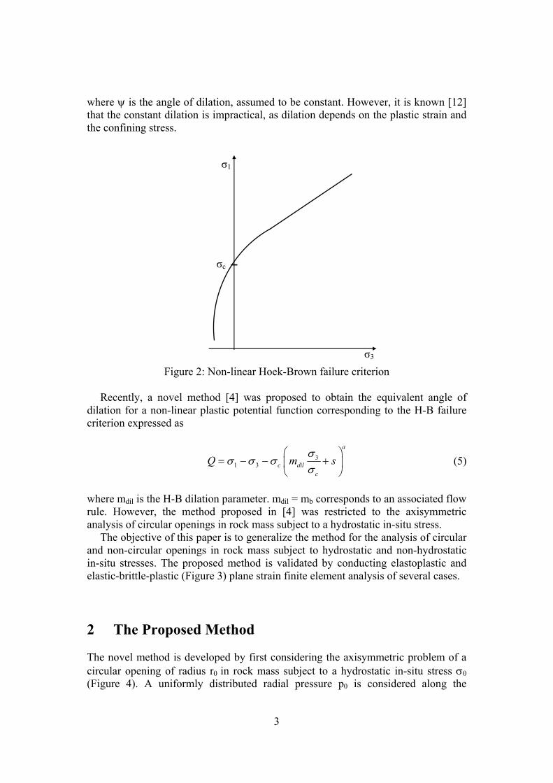
The M-C failure criterion is known to be unsuitable for many types of rock, particularly, discontinuous rock masses. For such rocks, the non-linear Hoek-Brown (H-B) failure criterion is more suitable [1, 2]. Figure 2 shows the failure envelope in the principal stresses space for this failure criterion expressed as
31 3
a
c bc
m sσ
σ σ σσ
⎛ ⎞= + +⎜ ⎟
⎝ ⎠(3)
where mb, s and a are the H-B constants [1] before yielding. Most of the computational tools in geotechnical engineering have not implemented the H-B failure criterion. One of the reasons for this may be that some computational difficulties arise in the use of this failure criterion due to its non-linearity [3, 4]. For the elastoplastic or elastic-brittle-plastic analysis, the results may not converge to the correct solution, particularly for a dilatant rock mass. In order to circumvent the above mentioned computational difficulties, several approaches [5, 6, 7, 8, 9, 10, 11] have been proposed to linearize the H-B failure criterion by obtaining equivalent M-C (EM-C) strength parameters. All of these approaches were based on a linear plastic potential function Q corresponding to the M-C failure criterion given by 1 3dQ Kσ σ= − (4a)
1 sin1 sindK ψ
ψ+
=−
(4b)
3
where ψ is the angle of dilation, assumed to be constant. However, it is known [12] that the constant dilation is impractical, as dilation depends on the plastic strain and the confining stress.
Figure 2: Non-linear Hoek-Brown failure criterion
Recently, a novel method [4] was proposed to obtain the equivalent angle of dilation for a non-linear plastic potential function corresponding to the H-B failure criterion expressed as
31 3
a
c dilc
Q m sσ
σ σ σσ
⎛ ⎞= − − +⎜ ⎟
⎝ ⎠(5)
where mdil is the H-B dilation parameter. mdil = mb corresponds to an associated flow rule. However, the method proposed in [4] was restricted to the axisymmetric analysis of circular openings in rock mass subject to a hydrostatic in-situ stress. The objective of this paper is to generalize the method for the analysis of circular and non-circular openings in rock mass subject to hydrostatic and non-hydrostatic in-situ stresses. The proposed method is validated by conducting elastoplastic and elastic-brittle-plastic (Figure 3) plane strain finite element analysis of several cases.
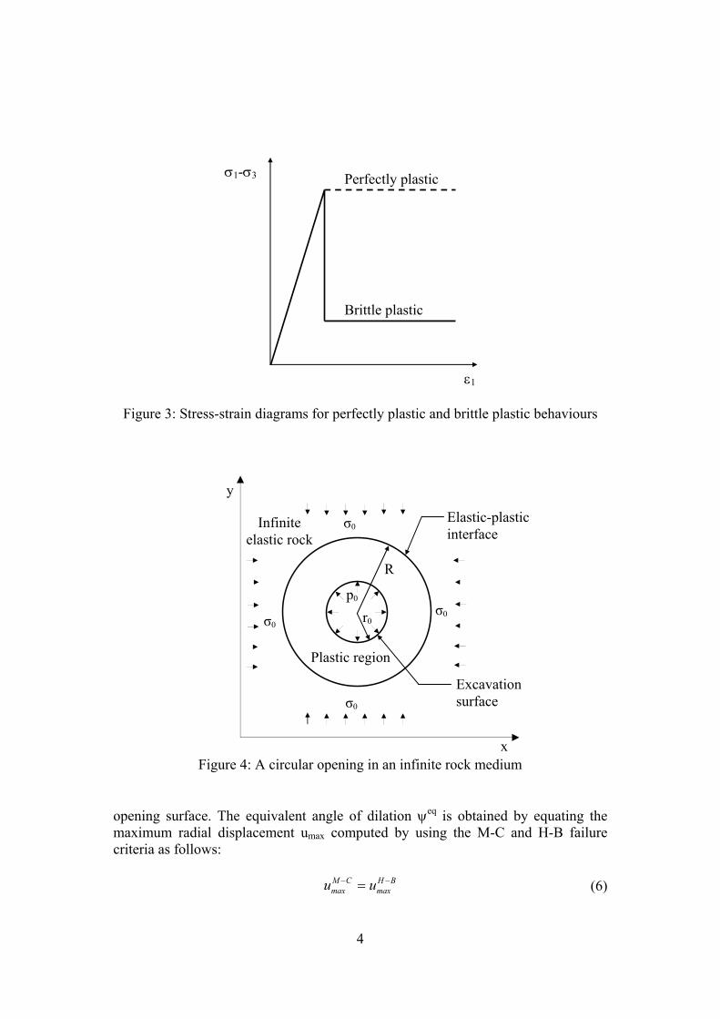
2 The Proposed Method The novel method is developed by first considering the axisymmetric problem of a circular opening of radius r0 in rock mass subject to a hydrostatic in-situ stress σ0 (Figure 4). A uniformly distributed radial pressure p0 is considered along the
σ3
σc
σ1
4
Figure 3: Stress-strain diagrams for perfectly plastic and brittle plastic behaviours
Figure 4: A circular opening in an infinite rock medium
opening surface. The equivalent angle of dilation ψeq is obtained by equating the maximum radial displacement umax computed by using the M-C and H-B failure criteria as follows: M C H B
max maxu u− −= (6)
ε1
Perfectly plastic
Brittle plastic
σ1-σ3
p0
R
r0 σ0
σ0
σ0
σ0
Elastic-plastic interface
Excavation surface
Plastic region
Infinite elastic rock
x
y
5
where the superscripts are used to denote the failure criteria used for the analysis. The maximum displacement occurs at the opening surface, r = r0. The radial displacements uM-C and uH-B are obtained by solving, respectively, the following equations for M-C and H-B failure criteria:
( )M C M C
eq e eq ed r d
du uK Kdr r θε ε
− −
+ = − + (7)
( )H B H B
e er
du uf fdr r θε ε
− −
+ = − + (8a)
1
1 a
rdil dil
c
f a m m sσσ
−⎛ ⎞
= + +⎜ ⎟⎝ ⎠
(8b)
where r and θ are the polar coordinates, εr
e and εθe are the elastic components of the
radial and circumferential strains given by
( )2
0 01
1er rE θ
ν νε σ σ σ σν
− ⎡ ⎤= − − −⎢ ⎥−⎣ ⎦(9)
( )2
0 01
1e
rEθ θν νε σ σ σ σ
ν− ⎡ ⎤= − − −⎢ ⎥−⎣ ⎦
(10)
and Kd
eq is the EM-C dilation parameter. A closed-form solution of Equation (7) may be found in [13]. The value of Kd
eq was computed by solving Equations (6) – (10) using a mathematical software. The equivalent angle of dilation was then obtained by using the following equation:
1 1
1
eqeq d
eqd
Ksin
Kψ − ⎛ ⎞−
= ⎜ ⎟+⎝ ⎠(11)
The results for Kd
eq are independent of the radius of the opening and therefore, the above method developed for circular openings was assumed to be applicable to non-circular openings as well. For the analysis of underground openings in rock mass subject to non-hydrostatic in-situ stresses, it was assumed that
10 300 2
σ σσ
+= (12)
where σ10 and σ30 are the major and minor principal in-situ stresses, respectively.
6
3 Numerical Validation In order to validate the proposed method, several example cases were tested numerically by using the finite element software Phase2 [14]. Five different cases were considered by varying the mechanical properties of rock mass, radius of the opening and support pressures. The data were taken from published work [15, 16, 17, 18] and are shown in Table 1. The subscript r used for H-B strength parameters correspond to the residual values.
The non-hydrostatic in-situ principal stresses σ10 and σ30 used for the analysis are
shown in Table 2. These correspond to σ10/σ30 =1.5. The value of a = ar = 0.5 was used and three different values of mdil = 0, mr/8 and mr/4 were considered. Eight-noded quadrilateral elements were used and the unbounded extent of rock mass was simulated by using infinite elements.
Table 2: Stress fields used for numerical validation
For all cases, the EM-C strength parameters c and φ were obtained by using the
BFe (best fitting in the existing stress range) procedure proposed in [9] and the equivalent angle of dilation ψeq was computed by using Equations (6) – (11).
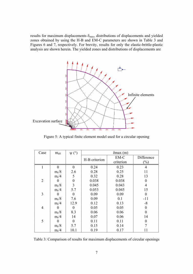
3.1 Circular Openings Figure 5 shows a typical finite element model for a circular opening. By using symmetry, only one quarter of the domain was analyzed. Typical comparisons of
7
results for maximum displacements δmax, distributions of displacements and yielded zones obtained by using the H-B and EM-C parameters are shown in Table 3 and Figures 6 and 7, respectively. For brevity, results for only the elastic-brittle-plastic analysis are shown herein. The yielded zones and distributions of displacements are
Infinite elements
Excavation surface
Figure 5: A typical finite element model used for a circular opening
Table 3: Comparison of results for maximum displacements of circular openings
8
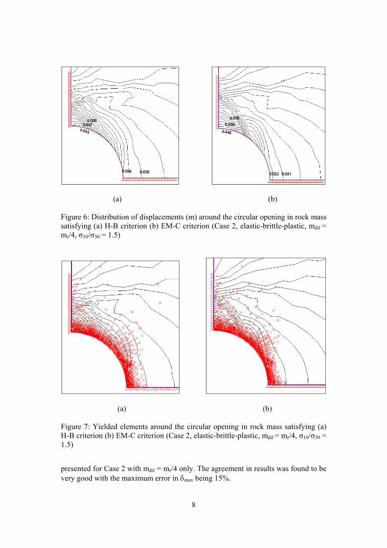
(a) (b) Figure 6: Distribution of displacements (m) around the circular opening in rock mass satisfying (a) H-B criterion (b) EM-C criterion (Case 2, elastic-brittle-plastic, mdil = mr/4, σ10/σ30 = 1.5)
(a) (b) Figure 7: Yielded elements around the circular opening in rock mass satisfying (a) H-B criterion (b) EM-C criterion (Case 2, elastic-brittle-plastic, mdil = mr/4, σ10/σ30 = 1.5)
presented for Case 2 with mdil = mr/4 only. The agreement in results was found to be very good with the maximum error in δmax being 15%.
9
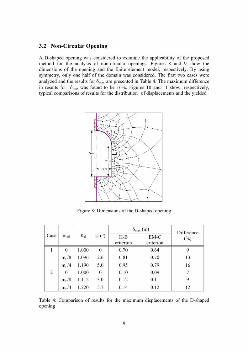
3.2 Non-Circular Opening A D-shaped opening was considered to examine the applicability of the proposed method for the analysis of non-circular openings. Figures 8 and 9 show the dimensions of the opening and the finite element model, respectively. By using symmetry, only one half of the domain was considered. The first two cases were analyzed and the results for δmax are presented in Table 4. The maximum difference in results for δmax was found to be 16%. Figures 10 and 11 show, respectively, typical comparisons of results for the distribution of displacements and the yielded
Table 4: Comparison of results for the maximum displacements of the D-shaped opening
10
Infinite elements Excavation surface
Figure 9: Finite element mesh for the D-shaped opening
(a) (b) Figure 10: Distribution of displacements (m) around the D-shaped opening in rock mass satisfying (a) H-B criterion (b) EM-C criterion (Case 2, elastic-brittle-plastic, mdil = mr/4, σ10/σ30 = 1.5)
11
zones for the elastic-brittle-plastic analysis of Case 2 with mdil = mr/4. The agreement in results was found to be very good.
(a) (b) Figure 11: Extent of yielded zone around the D-shaped opening in rock mass satisfying (a) H-B criterion (b) EM-C criterion. (Case 8, elastic-brittle-plastic, mdil = mr/4, σ10/σ30 = 1.5) 4 Conclusions A novel method was proposed to compute the equivalent M-C dilation parameter for the analysis of underground openings in rock mass governed by the non-linear H-B failure criterion and subject to a non-hydrostatic in-situ stress field. The method was found to be very effective and efficient for the plane strain elastoplastic and elastic-brittle-plastic finite element analysis of circular and non-circular underground openings. Acknowledgement The financial support provided by Laurentian University is gratefully acknowledged. References [1] E. Hoek, C. Carranza-Torres, B. Corkum, "Hoek-Brown failure criterion -
2002 edition", in “Proceedings of the North American Rock Mechanics Symposium”, Toronto, 2002.
12
[2] S.K. Sharan, "Analytical solutions for stresses and displacements around a circular opening in a generalized Hoek-Brown rock", International Journal of Rock Mechanics and Mining Sciences, 45, 78-85, 2008.
[3] R. Naznin, “Equivalent Mohr-Coulomb dilation parameter for Hoek-Brown rock”, M.A.Sc. thesis, Laurentian University, Sudbury, October, 2007.
[4] S.K. Sharan, R. Naznin, "Equivalent angle of dilation for the analysis of underground openings in rock mass obeying Hoek-Brown plasticity", in “Proceedings of the Twenty-third Canadian Congress of Applied Mechanics”, Vancouver, 140-143, 2011.
[5] E. Hoek, “Estimating Mohr-Coulomb friction and cohesion values from the Hoek-Brown failure criterion”, International Journal of Rock Mechanics and Mining Sciences and Geomechanics Abstract, 27(3), 227-229, 1990.
[6] E. Hoek, E.T. Brown, “Practical estimates of rock mass strength”, International Journal of Rock Mechanics and Mining Sciences and Geomechanics Abstract, 34, 1165-1186, 1997.
[7] A.I. Sofianos, N. Halakatevakis, “Equivalent tunneling Mohr-Coulomb strength parameters for given Hoek-Brown ones”, International Journal of Rock Mechanics and Mining Sciences, 39, 131-137, 2002.
[8] A.I. Sofianos, “Tunneling Mohr-Coulomb strength parameters for rock masses satisfying the generalized Hoek-Brown criterion”, International Journal of Rock Mechanics and Mining Sciences, 40, 435-440, 2003.
[9] A.I. Sofianos, P.P. Nomikos, “Equivalent Mohr-coulomb and generalized Hoek-Brown strength parameters for supported axisymmetric tunnels in plastic or brittle rock”, International Journal of Rock Mechanics and Mining Sciences, 43, 683-704, 2006.
[10] R. Jimenez, A. Serrano, C. Olalla, "Linearization of Hoek and Brown rock failure criterion for tunnelling in elasto-plastic rock masses", International Journal of Rock Mechanics and Mining Sciences, 45, 1153-1163, 2008.
[11] J. Shen, S.D. Priest, M. Karakus, “Determination of Mohr-Coulomb shear strength parameters from generalized Hoek-Brown criterion for slope stability analysis”, Rock Mechanics and Rock Engineering, 45, 123-129, 2012.
[12] E. Detournay, “Elastoplastic model of a deep tunnel for a rock with variable dilatancy”, Rock mechanics and Rock engineering, 19, 99-108, 1986.
[13] K.H. Park, Y.J. Kim, “Analytical solution for a circular opening in an elastic-brittle-plastic rock”, International Journal of Rock Mechanics and Mining Sciences, 43, 616-622, 2006.
[14] Rocscience Inc., “Phase2: Finite Element Analysis and Support Design for Excavations”, Rockscience Inc., Toronto, 2011.
[15] E. Hoek, E.T. Brown, “Underground Excavations in Rock”, Institution of Mining and Metallurgy, London, 1980.
[16] E.T. Brown, J.W. Bray, B. Ladanyi, E. Hoek, “Ground response curves for rock tunnels”, American Society of Civil Engineering, Journal of Geotechnical Engineering, 109, 15-39, 1983.
[17] E. Hoek, P.K. Kaiser, W.F. Bawden, “Support of Underground Excavations in Hard Rock”, Balkema, Rotterdam, 1998.
13
[18] C. Carranza-Torres, C. Fairhurst, “The elasto-plastic response of underground excavations in rock masses that satisfy the Hoek-Brown failure criterion”, International Journal of Rock Mechanics & Mining Sciences, 36, 777-809, 1999.


![Transient Wave Analysis for an Inhomogeneous Elastic Thick ...webapp.tudelft.nl/proceedings/ect2012/pdf/miura.pdf · al. [4] and Brekhovskikh [5] studied the wave propagation for](https://static.documents.pub/doc/80x56/5f5d8bf967316e7d86508efe/transient-wave-analysis-for-an-inhomogeneous-elastic-thick-al-4-and-brekhovskikh.jpg)


![Evaluation of Radial Basis Functions for the Deformation of …webapp.tudelft.nl/proceedings/ect2012/pdf/kouskour.pdf · 2012-07-31 · and unstructured grids. In [20] a very simple](https://static.documents.pub/doc/80x56/5f5b10503746c80512023d5b/evaluation-of-radial-basis-functions-for-the-deformation-of-2012-07-31-and-unstructured.jpg)


