Linearized Optimal Power Flow Model Incorporating Transformer-less UPFC Joydeep Mitra Energy Reliability & Security Laboratory Michigan State University East Lansing, MI 48824 January 21, 2015
Transcript
Linearized Optimal Power Flow Model Incorporating Transformer-less UPFC
Joydeep Mitra
Energy Reliability & Security Laboratory
Michigan State University
East Lansing, MI 48824
January 21, 2015
Outline
1
‣ Project objectives
‣ Optimal power flow model for UPFC benefit study
‣ Linearized power flow model of transformer-less UPFC
‣ Test case and data preparation
‣ Simulation and results
‣ Concluding remarks
Project Objectives
2
The overarching project objective was to develop models and methods for integration and impact analysis of transformer-less UPFC developed at MSU
‣ Develop UPFC model for power flow and OPF studies
‣ Perform cost-benefit analyses of transformer-less UPFC
‣ Determine optimal placement and parameter selection for transformer-less UPFC
‣ Determine the benefit of transformer-less UPFC at the location selected by utility or RTO
‣ Impact of real-time dispatch of UPFC to optimize system-wide power flows
Linearized Power Flow and OPF Models
3
‣ Traditional linearized models use DC power flow, which only provides information of real power flow and voltage angle values.
‣ Reactive power flow control and bus voltage regulation are important benefits that UPFC can provide; hence it was necessary to extend traditional DCOPF framework to accommodate reactive power injections and flows.
‣ The extended OPF framework incorporating reactive power flow and voltage magnitude also provides us a means to determine the optimal capacity of both series converter and parallel converter.
Linearized AC Power Flow Model Summary
4
'
'
P B G
Q G B V
11 11 12 1
21 22 22 2
1 2
...
...'
... ... ... ...
...
N
N
N N NN NN
B b B B
B B b BB
B B B b
11 11 12 1
21 22 22 2
1 2
...
...'
... ... ... ...
...
N
N
N N NN NN
G g G G
G G g GG
G G G g
11 12 1
21 22 2
1 2
...
...
... ... ... ...
...
N
N
N N NN
G G G
G G GG
G G G
11 12 1
21 22 2
1 2
...
...
... ... ... ...
...
N
N
N N NN
B B B
B B BB
B B B
Power Flow Model of Transformer-less UPFC
5
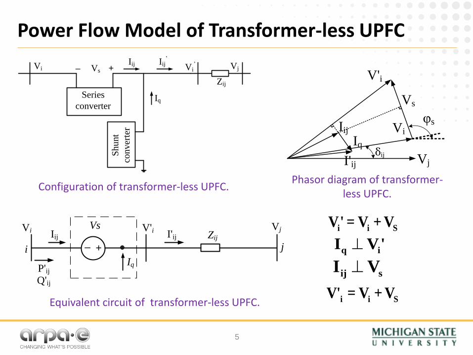
Configuration of transformer-less UPFC.
Equivalent circuit of transformer-less UPFC.
i i SV' = V + V
q iI V'
ij sI V
Phasor diagram of transformer-less UPFC.
i i SV' = V + V
Sh
un
t
con
ver
ter
Series
converter
Vi Vj
Iq
Vs Vi’
Zij
–Iij Iij
’
+
Vj
Vi
V'i
Vs
I'ij
Iij
Iq
φs
δij
i
Vi
j
VjZij
Iq
Vs V'i I'ijIij
+−
P'ijQ'ij
Linearization of Transformer-less UPFC Constraints
6
Linearized model of injected power:
Piece-wise linearization using six segments:
max maxS sp SV V V
max max2 3 2S sp sq SV V V V
max max2 3 2S sp sq SV V V V
i ij spP B V
( )i j i ij ij sqQ V V B B V
j ij spP B V
j ij sqQ B V
Capacity of series converter: max
maxseries S srS V I
Vsq
Vsp
060° Vsmax
cossq S SV V
sinsp S SV V
Test Systems and Data
7
‣ Initial testing and benchmarking of OPF model was performed with IEEE test cases: 30-bus, 57-bus, 118-bus and 300-bus
‣ Large-scale testing performed on
– FERC data set (PJM system) — completed
– MISO system data — in progress
‣ Challenges with large system data
– Most of the network data came in the form of PSS/E input files (.raw files)
– Hourly load data was generated by aligning load in .raw file with load shape files
– Network data in .raw files had numerous issues such as connectivity, line limits, etc. that needed “cleaning up”
– No data was available for reactive loads or generator reactive power limits
‣ Voltage magnitude limits (at bulk power buses) were set at 10% around nominal values.
‣ Shunt capacitors were assumed to be continuously dispatchable.
‣ Candidate locations for deployment of the transformer-less UPFC were selected by examining the shadow prices of transmission line constraints for major lines, prior to deploying UPFC. Cases with subsequent deployment were also examined to determine marginal benefits.
UPFC location: a 115 kV line from East Towanda to South Troy (PA) (maximum benefit case)
Profit
($/year)
Series
(MVA)
Shunt
(MVA)
Investment
($)
0.55 M 14.35 0 0.57 M
0 2 4 6 8 100
1
2
3
4
5
6
X: 10
Y: 0.9285
Year
X: 10
Y: 5.5
Mill
ion (
$)
Payment at 5% annual interest
Benefit (Savings)
Sample Results: Hourly Dispatch of UPFC
10
0 2000 4000 6000 80000
100
200
300
400
500
600
Hour (h)
Pro
fit ($
)
Hourly profits (savings)
0 2000 4000 6000 80000
0.02
0.04
0.06
0.08
0.1
0.12
0.14
Hour (h)|V
| (p
u)
Hourly voltage injections into series branch
Sample Results: Reduction of Loop Flows
11
Hourly flows across PJM-ECAR interface (before and after UPFC deployment)
0 2000 4000 6000 8000 10000-0.2
-0.1
0
0.1
0.2
0.3
0.4
0.5
0.6
Tie
lin
e f
low
(p
u)
0 2000 4000 6000 8000 10000-0.1
0
0.1
0.2
0.3
0.4
0.5
0.6
Tie
lin
e f
low
(p
u)
Sample Results: Increase of Wind Power Injection
12
Hourly wind power injection from 800 MW (8 pu) wind farm (before and after UPFC deployment); average hourly intake increased by 37 MW, which is 4.63%
of nameplate capacity; total annual energy intake increased by 324 GWh.
0 2000 4000 6000 80000
1
2
3
4
5
6
Hour
Win
d F
arm
ou
tpu
t (p
u)
0 2000 4000 6000 80000
1
2
3
4
5
6
7
HourW
ind
Farm
ou
tpu
t (p
u)
Concluding Remarks
13
‣ Linearized model for AC optimal power flow was developed and benchmarked. Inclusion of loss compensation resulted in very high accuracy (<0.15% error in total cost for IEEE 300-bus case).
‣ Linearized model was developed for UPFC operation.
‣ Large-scale test cases were used for several studies: – Cost savings through congestion reduction; – Hourly dispatch for power flow control; – Reduction of loop flows; – Increase of wind power injection.
‣ Absence of large benchmark systems is still a challenge. Data sets large systems require considerable work.
‣Work on developing business cases for transformer-less UPFC is ongoing.
Acknowledgments
14
‣Financial support from ARPA-E is gratefully acknowledged.
‣The project team benefited significantly from discussions with Colin Schauder, Tim Heidel, and Josh Gould.
‣Dr. Niannian Cai (my prior doctoral student and post-doc, now with Schweitzer Engineering Laboratories, Pullman, WA) performed the bulk of the implementation, programming, and simulation. He also prepared much of this presentation.


![Incorporating signals into optimal trading · – Cartea and Jaimungal (CJ) framework [13], where the market impact is instanta-neous and the fuel constraint on the strategies is](https://static.documents.pub/doc/80x56/5e268903318e6a661920b85b/incorporating-signals-into-optimal-trading-a-cartea-and-jaimungal-cj-framework.jpg)


