Linewidth reduction of a broad-area laser diode array ina compound external cavity
Bo Liu,1,* Yun Liu,2 and Yehuda Braiman1
1Center for Engineering Science Advanced Research, Computer Sciences & Mathematics Division,Oak Ridge National Laboratory, Oak Ridge, Tennessee 37831, USA
2Research Accelerator Division, Oak Ridge National Laboratory, Oak Ridge, Tennessee 37831, USA
High power broad area semiconductor laser diode ar-rays (LDAs) provide a valuable source for pumpingsolid state lasers, fiber lasers, and alkali vaporlasers, and have many applications including mate-rials processing and illumination. The main advan-tages of LDAs include long lifetime, compactness,and high electro-optical conversion efficiency. Insome applications such as spin-exchange opticalpumping (SEOP) and pumping of alkali-vapor lasers[1–4], achieving a narrow spectral linewidth (fullwidth at half-maximum) is critical in increasingthe pumping efficiency. Typically, an LDA has a line-width of 1THz (2nm), which is much larger than, forexample, the absorption linewidth of Rb in the pre-sence of 3He (18GHz per amagat of 3He) [2]. Follow-ing an example in Refs. [5,6], a frequency-narrowed,30-W LDA with a linewidth of 65GHz produces apumping rate of approximately one order of
magnitude higher than that of the unnarrowed (typi-cal), 60-W LDA with a linewidth of 1THz.
In general, the LDA linewidth reduction is realizedby using an external wavelength selection feedback,which is extensively studied in single laser diodelinewidth reduction. Two approaches have beensuccessfully used to reduce LDA linewidth: one is aLittrow or Littman–Metcalf mounted plane diffrac-tive grating external cavity [5–7], the other is a vo-lume Bragg grating (VBG) external cavity [8–10].The spectral selectivity of a reflective VBG is deter-mined by the number of Bragg planes in the VBG. Inorder to increase the spectral selectivity of the VBG,the number of Bragg planes in the VBG has to be in-creased. The large number of Bragg planes makesthe VBG thick and absorptive. The active coolingis required to remove heat generated by thick VBGabsorption and to accurately tune the wavelength.The thick volume Bragg grating external cavity canachieve a narrow linewidth at an order of 15GHz, butthe tunable wavelength range is limited to only0:4nm [10]. Meanwhile, the plane-grating externalcavity provides a larger tunable spectrum rangearound 10nm with a linewidth of 0:1nm [5,6]. In
both cases, each laser diode (LD) essentially has itsown external cavity, and the entire LDA spectrum isthe sum of the individual LDs. The entire LDA line-width is determined by both the individual LD spec-tral linewidth and inhomogeneous spectrumdistribution. The individual LD spectral linewidthis determined by the spectrum-selection feedback,while the inhomogeneous spectrum distribution iscaused by nonuniform feedback to individual LDs.Specifically, in the case of optical feedback from anexternal grating the beam incidence angles on thegrating surface from individual LDs are slightlydifferent due to the “smile” effect, i.e., a curved dis-tribution of the LD vertical position, and alignmenterrors (GRIN lens alignment error and other opticsalignment errors). Consequently, the locking wave-length for individual LDs will be different, and thelinewidth of the entire LDA broadens.Reducing the smile effect and alignment errors
poses significant challenges. Chann et al. employeda magnifying telescope in the external cavity to soft-en the smile effect [5,6]. Talbot et al. tilted the cylind-rical lens to correct the large “smile” [7]. Zhdanovet al. reduced the smile effect by choosing a longerfocal length GRIN lens [11]. Gopinath et al. reducedthe smile effect by using a large magnification tele-scope formed by a long focal length cylindrical lensand GRIN lens [12]. Hall et al. employed a microma-chined phase mask to correct the optical path differ-ence in the fast-axis direction [13], and this methodwas used to a tapered laser diode array [14].In this paper, we propose a new approach to
achieve the linewidth reduction of the single laserdiode array by increasing optical coupling amonglaser emitters in the array. The optical coupling ar-ray is very important since it introduces interactionamong laser emitters, and therefore a synchronizedstate of the laser array can be realized through a self-organization process. Since the distance betweenlaser emitters in the broad-area laser is much largerthan the wavelength, evanescent nearest neighborcoupling cannot be realized. A Talbot cavity is oneefficient way of realizing optical diffraction couplingamong laser diodes. A Talbot cavity utilizes theTalbot effect, i.e., a periodic distribution coherentlight source diffracts and forms a self-image atcertain distances (Talbot lengths) along the light pro-pagation direction [15–17]. The laser diode arrange-ment on an array is a natural periodic lightdistribution. By locating the external reflector at cer-tain distances (e.g., half Talbot length) from the laserarray, a self-image of the laser array can be effec-tively fed back on the array surface. However, whenthe external reflector is a diffractive grating, thegrating generates the spectrum-resolved feedback.Due to the array smile effect and other alignment er-rors, the light from each laser diode is incident on thegrating surface at a slightly different angle. Each la-ser diode is equivalently having a different Littrowexternal cavity with a different resonant frequency.Accordingly, the optical feedback from one laser
diode may not be resonant with other laser diodecavities. In other words, the feedback light from onelaser diode may not be amplified in the Littrow ex-ternal cavities of other laser diodes. As a result,the coupling strength among laser diodes in the ar-ray weakens when the external reflector is a diffrac-tive grating and the smile effect and other alignmenterrors exist. In order to build effective couplingamong laser diodes in an array, we introduce a par-tial reflector (also called an optical coupler in this pa-per) in the Littrow external cavity and form acompound external cavity. The optical coupler pro-vides nonspectrum resolved feedback andmakes am-plification of diffraction feedback from different laserdiodes feasible even though the smile effect and otheralignment errors exist. With the proposed compoundexternal cavity, we have obtained a uniform spec-trum distribution of 49 laser diodes in the arrayand achieved a narrow linewidth of the entire array.
2. Experiment
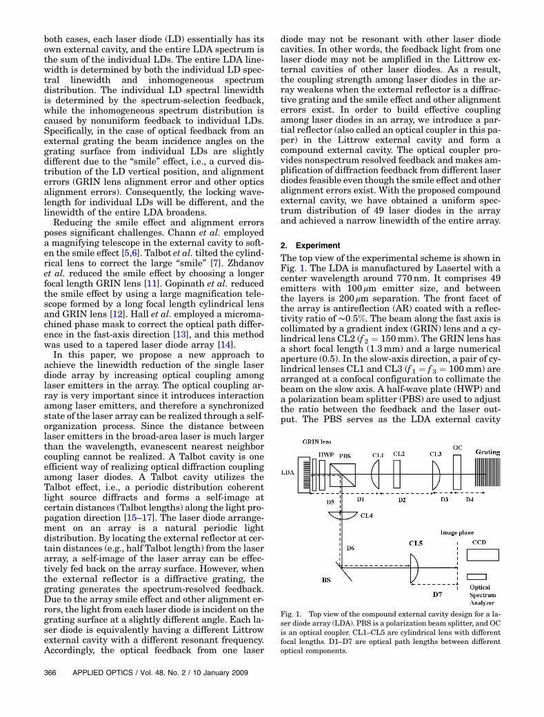
The top view of the experimental scheme is shown inFig. 1. The LDA is manufactured by Lasertel with acenter wavelength around 770nm. It comprises 49emitters with 100 μm emitter size, and betweenthe layers is 200 μm separation. The front facet ofthe array is antireflection (AR) coated with a reflec-tivity ratio of ∼0:5%. The beam along the fast axis iscollimated by a gradient index (GRIN) lens and a cy-lindrical lens CL2 (f 2 ¼ 150mm). The GRIN lens hasa short focal length (1:3mm) and a large numericalaperture (0.5). In the slow-axis direction, a pair of cy-lindrical lenses CL1 and CL3 (f 1 ¼ f 3 ¼ 100mm) arearranged at a confocal configuration to collimate thebeam on the slow axis. A half-wave plate (HWP) anda polarization beam splitter (PBS) are used to adjustthe ratio between the feedback and the laser out-put. The PBS serves as the LDA external cavity
Fig. 1. Top view of the compound external cavity design for a la-ser diode array (LDA). PBS is a polarization beam splitter, and OCis an optical coupler. CL1–CL5 are cylindrical lens with differentfocal lengths. D1–D7 are optical path lengths between differentoptical components.
output coupler. A diffraction grating (830 × lines=mm) with gold coating is mounted in a Littrow con-figuration with the grove vertical to the array direc-tion [18]. The grating blaze angle is about 18 degrees,and the first-order diffraction beam reflects morethan 85% of the incident beam. An optical coupleris mounted on a linear stage that can be moved be-tween CL3 and the grating. The locations of lensesand the optical coupler are determined by the follow-ing relationships: D1 ¼ f 1 þ Zt=2, D2 ¼ f 1 þ f 3,D3 ¼ f 3, and D4 ¼ f 3, where Zt ¼ 2d2=λ is the Talbotdistance [15–17], λ is the laser wavelength, and d isthe array pitch. Consequently, the optical coupler islocated at the Talbot cavity position (cavity roundtrip equal to Talbot length) so that the self-imageof the laser array will be reflected back.As for the measurement path, a confocal cylindri-
cal lens pair CL4 (f 4 ¼ 300mm) and CL5 (f 5 ¼200mm) projects the laser diode array image atthe focal plane of CL5. A CCD camera and a GRINlens collimated fiber are mounted on a linear stageto detect the image and spectrum of the laser diodes.The fiber is connected to an Agilent optical spectrumanalyzer 86140B with a resolution of 0:07nm. Bymoving the linear stage, we are able to measurethe spectra of individual laser diodes.The side view of the Littrow external cavity is
shown in Fig. 2(a). In the Littrow external cavity,the transformation optics consists of cylindricallenses that make our design different from the tele-scope design [5,6]. The front facet of the LDA is ARcoated, and therefore the laser resonator is formedfor each laser emitter between the high-reflectioncoating rear facet and the diffraction grating. Thetransformation lenses and the grating are commonoptical elements of the external cavity shared byall the laser emitters. The smile effect on the wave-length can be determined according to the standardray tracing formula [5,6]
δλλ ¼ δx · cot θ
Mf FAC; ð1Þ
where δx is the smile size along the laser array, θ isthe grating diffraction angle, and λ is the lasingwavelength. Comparing Eq. (1) with Eq. (2) inRef. [2], we find that our external cavity has a mag-nification M ¼ f 2=ðd1 − f 2 − f FACÞ, where d1 is thedistance between the GRIN lens and cylindrical lens
CL2, and f 2 and f FAC are the focal lengths of cylind-rical lens CL2 and the GRIN lens, respectively. In ourexternal cavity (d1 ¼ 170mm), the magnificationM ¼ 8 and therefore the spectrum distribution dueto the “smile” effect is reduced by a factor of 8.The detailed derivation is presented in Appendix A.
Figure 2(b) shows the side view of the compoundexternal cavity where the optical coupler is insertedinto the Littrow external cavity and is located at thehalf-Talbot plane. The optical coupler provides a non-spectrum resolved feedback, and therefore each laserdiode cavity is composed of laser diode and opticalcoupler and is not sensitive to losing frequency.The optical feedback from different laser diodescan be amplified in laser diode cavities. The effectivetransverse coupling among laser diodes is enhancedby introducing an optical coupler in the Littrow ex-ternal cavity.
3. Results and Discussion
In order to demonstrate the effect of the optical cou-pler, we conducted experiments with a special laserarray where the first (left edge in Fig. 1) laser emitterhas an uncoated laser facet. At the injection currentof 30A, the uncoated laser emitter shows a broadspectrum around 768nm, while the rest of the laseremitters are not lasing without external feedback.Figures 3(a) and 3(b) show the sampled spectra ofthe laser diodes in an array with (a) the feedbackfrom the Littrow external cavity and (b) the feedbackfrom the compound external cavity. In either case, alllaser emitters are well locked to the wavelength of765:0nm determined by the grating except the firstlaser, which exhibits a narrow peak corresponding tothe grating feedback and a broad side spectrum peak
Fig. 2. (a) Side view of the LDA Littrow external cavity. (b) Sideview of the compound external cavity that consists of an opticalcoupler and the Littrow external cavity.
Fig. 3. (Color online) (a) Sampled individual spectra of LDs in theLDA consisted of 49 lasers for the Littrow external cavity (withoutan optical coupler) LDA (the sidemode is observed only in the spec-trum of the first LD that is not coated) and (b) the compound ex-ternal cavity (with an optical coupler) LDA (the side mode of thefirst LD appears on spectra of all the other lasers). The spectralpeak position variation for the compound external cavity is lessthan for the Littrow external cavity.
originating from its own uncoated facet. The sidespectrum peak does not appear in the spectra ofother lasers in Fig. 3(a), which indicates that thefeedback from first laser does not affect the spectraof other lasers in the array. The optical feedback fromfirst laser diode broad spectrum was not amplified inother laser diodes cavities due to the strong spectrumselection of the grating. In other words, only spec-trum overlapping feedback can be effectively ampli-fied in Littrow external cavities of different laserdiodes.An optical coupler provides a nonspectrum re-
solved optical feedback. When the optical coupleris inserted in the Littrow external cavity, the broadside peak appears in the spectra of all lasers asshown in Fig. 3(b). This clearly confirms that theemission from the first LD is efficiently coupled intoand amplified by the rest of the LD cavities in an ar-ray. The efficient coupling is built by introducing anoptical coupler in a Littrow external cavity.In order to confirm the coupling enhancement, we
conducted an experiment with a different laser diodearray that does not have AR-coating defects. Figure 4shows the distribution of the center frequency of in-dividual laser diodes in both Littrow and compoundexternal cavities at an injection current of 30A. Thespectrum shows large spread due to the smile effectof the laser array and possible collimation lens align-ment (GRIN lens and cylindrical lenses) error. Theinhomogeneous spectrum distribution is shown asa solid-square curve in Fig. 4. This leads to a broad-ening of the linewidth of the entire laser array. Suchfrequency inhomogeneity is effectively suppressedby the compound external cavity, as noted by theopen-circle curve in Fig. 4. The optical coupler iscarefully aligned to maximize the output power. Thecoupler reflectivity is high (R ¼ 40%) in order tocompensate the cavity loss at low current operation.The linewidth of each LD is reduced to less than
0:1nm, and the inhomogeneity of the entire arrayis reduced to 0:04nm. Without an optical coupler,the spectrum inhomogeneity of the array was mea-sured to be 0:09nm. Therefore, the compound exter-nal cavity reduces the spectrum inhomogeneity bymore than a factor of 2. As we demonstrated in Fig. 3,the optical coupler enhances nonspectrum selectivediffraction coupling among laser emitters via theoptical feedback, and such mutual coupling greatlyenhances the spectrum homogeneity of the frequencylocking. The spectrum curvature distributions gener-ated by the smile effect and GRIN lens alignment er-rors are further reduced by the compound externalcavity.
The curvature of laser diodes along the fast-axisdirection was measured to compare with the spec-trum distribution. The “smile” of the laser diode ar-ray was measured to be ∼0:5 μm, as shown in Fig. 5.Using this smile size and Eq. (1), we calculated themaximum wavelength difference to be about 0:1nm.The result is close to the experimental measurementas shown by solid squares in Fig. 4. It is important tonote that the GRIN lens is already involved in thesmile measurement. The “smile” in this paperincluded the GRIN lens alignment errors and thereal “smile”, i.e., curvature distribution of verticalposition of laser diodes along array.
In practical applications, we are more interested inthe spectrum homogeneity and linewidth reductionat high power levels. Figure 6 shows the experimen-tal results with the LDA driven at the 50A injectioncurrent. The optical coupler with a 30% reflectance isused. The lower reflectance optical coupler ismatched with LDA high current operation. We havemeasured a total of 24 spectra for compound externalcavity configurations. The peak position of each spec-trum is shown in Fig. 6(a). The individual spectrumof compound external cavity LDA is more uniformthan the spectra achieved with the Littrow externalcavity. The variation of the frequency peak positionwas reduced from 0:09nm to 0:04nm. The spectrumof the entire LDA (equal to the sum of all individualspectrums of LDs in an array) is shown in theFig. 6(b). The total LDA linewidth is reduced to0:1nm when an optical coupler is properly alignedand emission power from an array is increased by12.6%. The output power reaches 12.5 W. For com-parison, by using a Littrow external cavity withoutoutput coupler, we obtained 0:12nm spectral line-
Fig. 4. Spectral peak position distribution of the LDA with theLittrow external cavity (solid-square curve) and the compound ex-ternal cavity (open-circle curve). The LDA is driven by a 30A in-jection current.
Fig. 5. Curvature of the laser diode image with a GRIN lens col-limation with a 0:5 μm smile.
width and 10.0 W output power at 50 A currentdriven.We have measured 12:5W of frequency narrowed
power from an array with a total output power equalto 25W. The LDA linewidth is reduced from 2:3nm to0:1nm, and the beam divergence (slow axis) is re-duced from 12 degrees to 3.5 degrees. The divergenceangle reduction is due to the common external cavityfor all laser emitters. The output to total power ratiois lower compared with the results in Refs. [5,6] sincein our experimental configuration the output couplerPBS involved 50% loss due to the feedback from theexternal cavity. The feedback efficiency is not opti-mized, which results in the loss of 20–30% in the out-put power. We believe that using a higher densityLittrow-mounted holographic grating (2000 × lines=mm) as an output coupler will improve feedback ef-ficiency and consequently increase output power toapproximately 18–20W.Moreover, a high density ho-lographic grating may further reduce the linewidthof each laser diode.
4. Conclusion
In summary, we have demonstrated an effectivemethod to narrow the broad-area laser diode line-width by using a compound external cavity thatconsists of a Littrow external cavity and an opticalcoupler located at the Talbot cavity position. Thecompound external cavity reduces the smile effectand alignment errors through enhancing the opticalcoupling among laser emitters in the array, resultingin an homogeneous wavelength stabilization andtherefore in a narrow linewidth of the entire array.Using the proposed compound external cavity, weare able to reduce the linewidth of a 49-emitter laserarray to 0:1nm at an output power of 12:5W. Ourmethod is based on optical coupling enhancementand is scalable to higher power laser arrays includingstacked arrays.
Appendix A
The lasing wavelength variation due to the smile ef-fect can be calculated following the ray-tracing meth-od. The “smile” is the laser diode vertical position(fast-axis direction) variation along the array. Thelasing wavelength is determined by the grating equa-tion with the Littrow condition. Figure 7 is a simpli-fied version of Fig. 2(a). We omitted slow-axiscollimation cylindrical lenses CL1 and CL3 sincethey do not change the fast-axis light propagation.
According to the ABCD law, the transformationray can be calculated by multiplexing transformmatrices,
�x
θ
�¼
�1 d2
0 1
�� 1 0
−
1f 1
��1 d1
0 1
�
� 1 0
−
1f FAC
1
��1 d0
0 1
��x1θ1
�; ðA1Þ
where d0 is the distance between the laser diode andthe GRIN lens, f FAC is the GRIN lens focal distance,d1 is the distance between the GRIN lens and cylind-rical lens CL2, f is the cylindrical lens CL2 focallength, d2 is the distance between CL2 and grating,ðx1; θ1Þ are the initial ray parameters, and ðx; θÞ arethe ray parameters before the ray hits the grating.
The incidence angle is related to the initial laserdiode vertical position and beam angle as
θ ¼�−
1f−
1f FAC
þ d1
f f FAC
�x1
þ�d0
�−
1f−
1f FAC
þ d1
f f FAC
�þ 1 −
d1
f
�θ1: ðA2Þ
The change in incidence angle due to the smileeffect–vertical position change along the array is
Fig. 6. (a) Spectral peak positions of the sampled laser emittersand (b) the spectrum of the entire LDA. The LDAwas driven by aninjection current of 50A, and we employed the compound externalcavity.
Fig. 7. Diagram of light propagation along the fast-axis direction.
ðA3Þwhere δx1 is smile size, and δθ is angle variation dueto smile.According to the Littrow grating condition,
λ ¼ 2d sin θ, where λ is the laser wavelength, d isthe grating period, and θ is the first order diffractionangle, and the wavelength change depends on thegrating angle change as
δλ ¼ 2d cos θδθ ¼ 2d sin θðcos θ= sin θÞδθ ¼ λ cot θδθ:ðA4Þ
Substituting Eq. (A3) into Eq. (A4) gives the wave-length variation as a function of the smile effect,
δλ ¼ λδθ cot θ ¼ λd1 − f − f FACf × f FAC
δx1 cot θ ¼ λ cot θδx1Mf FAC
;
ðA5Þwhere M ¼ f =ðd1 − f − f FACÞ.
This research was supported by the Office of NavalResearch (ONR) and the Laboratory DirectedResearch and Development Program of Oak RidgeNational Laboratory. Oak Ridge National Labora-tory is managed by UT-Battelle, LLC for the U.S.Department of Energy (DoE) under contract DE-AC05-00OR22725.
References1. T. G. Walker and W. Happer, “Spin-exchange optical pumping
of noble-gas nuclei,” Rev. Mod. Phys. 69, 629–642 (1997).2. M. V. Romalis, E. Miron, and G. D. Cates, “Pressure broaden-
ing of Rb D1 and D2 lines by 3He, 4He, N2, and Xe: line coresand near wings,” Phys. Rev. A 56, 4569–4578 (1997).
3. B. Zhdanov, C. Maes, T. Ehrenreich, A. Havko, N. Koval, T.Meeker, B. Worker, B. Flusche, and R. J. Knize, “Opticallypumped potassium laser,”Opt. Commun. 270, 353–355 (2007).
4. B. Zhdanov and R. J. Knize, “Diode-pumped 10W continuouswave cesium laser,” Opt. Lett. 32, 2167–2169 (2007).
5. B. Chann, I. Nelson, and T. G. Walker, “Frequency-narrowedexternal-cavity diode-laser-array bar,” Opt. Lett. 25,1352–1354 (2000).
6. E. Babcock, B. Chann, I. A. Nelson, and T. G. Walker,“Frequency-narrowed diode array bar,” Appl. Opt. 44, 3098–3104 (2005).
7. C. L. Talbot, M. E. J. Frese, D. Eang, I. Brereton,N. R. Heckenberg, and H. Rubinsztein-Dunlop, “Linewidth re-duction in a large-smile laser diode array,” Appl. Opt. 44,6264–6268 (2005).
8. L. S. Meng, B. Nizamov, P. Madasamy, J. K. Brasseur,T. Henshaw, and D. K. Neuman, “High power 7-GHz band-width laser array and its use in optically pump singlet deltaoxygen,” Opt. Express 14, 10469–10474 (2006).
9. G. J. Steckman, W. Liu, R. Platz, D. Schroeder, C. Moser, andF. Havermeyer, “Volume holographic grating wavelength sta-bilized laser diodes,” IEEE J. Sel. Top. Quantum Electron. 13,672–678 (2007).
10. A. Gourevitch, G. Venus, V. Smirnov, D. A. Hostutler, andL. Glebov, “Continous wave, 30W laser-diode bar with10GHz linewidth for Rb laser pumping,” Opt. Lett. 33,702–704 (2008).
11. B. V. Zhdanov, T. Ehrenreich, and R. J. Knize, “Narrowbandexternal cavity laser diode array,” Electron. Lett. 43, 221–222 (2007).
12. J. T. Gopinath, B. Chann, T. Y. Fan, and A. Sanchez-Rubio,“1450-nm high-brightness wavelength-beam combined diodelaser array,” Opt. Express 16, 9405–9410 (2008).
13. J. F. Monjardin, K. M. Nowak, H. J. Baker, and D. R. Hall,“Correction of beam errors in high power laser diode barsand stacks,” Opt. Express 14, 8178–8183 (2006).
14. G. L. Bourdet, I. Hassiaoui, R. McBride, J. F. Monjardin,H. Baker, N. Michel, and M. Krakowski, “High-power, low-divergence, linear array of quasi-diffraction-limited beamssupplied by tapered diodes,” Appl. Opt. 46, 6297–6301(2007).
15. J. R. Leger, M. L. Scott, and W. B. Veldkamp, “Coherent addi-tion of AlGaAs lasers using microlenses and diffractive cou-pling,” Appl. Phys. Lett. 52, 1771–1773 (1988).
16. J. R. Leger, “Lateral mode control of an AlGaAs laserarray in a Talbot cavity,” Appl. Phys. Lett. 55, 334–336(1989).
17. F. X. D’Amato, E. T. Siebert, and C. Roychoudhuri,“Coherent operation of an array of diode lasers using aspatial filter in a Talbot cavity,” Appl. Phys. Lett. 55,816–818 (1989).
18. Y. Liu and Y. Braiman, “Synchronization of high-power broad-area semiconductor lasers,” IEEE J. Sel. Top. Quantum Elec-tron. 10, 1013–1024 (2004).