5: DataLink Layer 5a-1 14: Ethernet, Hubs, Bridges, Switches, Other Technologies used at the Link Layer, ARP Last Modified: 4/9/2003 1:14:12 PM 5: DataLink Layer 5a-2 Link Layer: Implementation ❒ Typically, implemented in “adapter” ❍ e.g., PCMCIA card, Ethernet card ❍ typically includes: RAM, DSP chips, host bus interface, and link interface application transport network link physical network link physical M M M M Ht Ht Hn Ht Hn Hl M Ht Hn Hl frame phys. link data link protocol adapter card 5: DataLink Layer 5a-3 Link Layer Services ❒ Framing, link access: ❍ encapsulate datagram into frame, adding header, trailer ❍ implement channel access if shared medium, ❍ ‘physical addresses’ used in frame headers to identify source, dest • different from IP address! ❒ Reliable delivery between two physically connected devices: ❍ we learned how to do reliable delivery over an unreliable link ❍ seldom used on low bit error link (fiber, some twisted pair) ❍ wireless links: high error rates • Q: why both link-level and end-end reliability? 5: DataLink Layer 5a-4 Link Layer Services (more) ❒ Flow Control: ❍ pacing between sender and receivers ❒ Error Detection: ❍ errors caused by signal attenuation, noise. ❍ receiver detects presence of errors: • signals sender for retransmission or drops frame ❒ Error Correction: ❍ receiver identifies and corrects bit error(s) without resorting to retransmission 5: DataLink Layer 5a-5 LAN technologies Data link layer so far: ❍ services, error detection/correction, multiple access Next: LAN technologies ❍ Ethernet ❍ hubs, bridges, switches ❍ 802.11 ❍ PPP ❍ ATM 5: DataLink Layer 5a-6 Ethernet “dominant” LAN technology: ❒ cheap $20 for 100Mbs! ❒ first widely used LAN technology ❒ Simpler, cheaper than token LANs and ATM ❒ Kept up with speed race: 10, 100, 1000 Mbps Metcalfe’s Ethernet sketch
Transcript
1
5: DataLink Layer 5a-1
14: Ethernet, Hubs, Bridges, Switches, Other Technologies used at the Link Layer, ARP
Last Modified: 4/9/2003 1:14:12 PM
5: DataLink Layer 5a-2
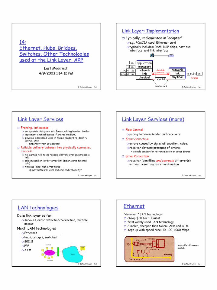
Link Layer: Implementation❒ Typically, implemented in “adapter”
❍ e.g., PCMCIA card, Ethernet card ❍ typically includes: RAM, DSP chips, host bus
interface, and link interface
applicationtransportnetwork
linkphysical
networklink
physical
MMMM
Ht
HtHn
HtHnHl MHtHnHl
framephys. link
data linkprotocol
adapter card
5: DataLink Layer 5a-3
Link Layer Services❒ Framing, link access:
❍ encapsulate datagram into frame, adding header, trailer❍ implement channel access if shared medium, ❍ ‘physical addresses’ used in frame headers to identify
source, dest • different from IP address!
❒ Reliable delivery between two physically connected devices:
❍ we learned how to do reliable delivery over an unreliable link
❍ seldom used on low bit error link (fiber, some twisted pair)
❍ wireless links: high error rates• Q: why both link-level and end-end reliability?
5: DataLink Layer 5a-4
Link Layer Services (more)
❒ Flow Control:❍ pacing between sender and receivers
❒ Error Detection:❍ errors caused by signal attenuation, noise. ❍ receiver detects presence of errors:
• signals sender for retransmission or drops frame
❒ Error Correction:❍ receiver identifies and corrects bit error(s)
Next: LAN technologies❍ Ethernet❍ hubs, bridges, switches❍ 802.11❍ PPP❍ ATM
5: DataLink Layer 5a-6
Ethernet“dominant” LAN technology: ❒ cheap $20 for 100Mbs!❒ first widely used LAN technology❒ Simpler, cheaper than token LANs and ATM❒ Kept up with speed race: 10, 100, 1000 Mbps
Metcalfe’s Ethernetsketch
2
5: DataLink Layer 5a-7
Ethernet Frame StructureSending adapter encapsulates IP datagram (or other
network layer protocol packet) in Ethernet frame
Preamble:❒ 7 bytes with pattern 10101010 followed by one
byte with pattern 10101011❒ used to synchronize receiver, sender clock rates
5: DataLink Layer 5a-8
Ethernet Frame Structure (more)❒ Addresses: 6 bytes, frame is received by all
adapters on a LAN and dropped if address does not match
❒ Type: indicates the higher layer protocol, mostly IP but others may be supported such as Novell IPX and AppleTalk)
❒ CRC: checked at receiver, if error is detected, the frame is simply dropped
5: DataLink Layer 5a-9
Ethernet: uses CSMA/CDA: sense channel, if idle
then {transmit and monitor the channel; If detect another transmission
then { abort and send jam signal; update # collisions; delay as required by exponential backoff algorithm; goto A}
else {done with the frame; set collisions to zero}}
else {wait until ongoing transmission is over and goto A}
5: DataLink Layer 5a-10
Ethernet’s CSMA/CD (more)
Jam Signal: make sure all other transmitters are aware of collision; 48 bits;
Exponential Backoff:❒ Goal: adapt retransmission attempts to estimated
current load❍ heavy load: random wait will be longer
❒ first collision: choose K from {0,1}; delay is K x 512 bit transmission times
❒ after second collision: choose K from {0,1,2,3}…❒ after ten or more collisions, choose K from
{0,1,2,3,4,…,1023}
5: DataLink Layer 5a-11
Ethernet Technologies: 10Base2❒ 10: 10Mbps; 2: under 200 meters max cable length❒ thin coaxial cable in a bus topology
❒ repeaters used to connect up to multiple segments❒ repeater repeats bits it hears on one interface to
its other interfaces: physical layer device only!5: DataLink Layer 5a-12
10BaseT and 100BaseT
❒ 10/100 Mbps rate; latter called “fast ethernet”❒ T stands for Twisted Pair❒ Hub to which nodes are connected by twisted pair,
thus “star topology”❒ CSMA/CD implemented at hub
3
5: DataLink Layer 5a-13
10BaseT and 100BaseT (more)
❒ Max distance from node to Hub is 100 meters❒ Hub can disconnect “jabbering adapter”❒ Hub can gather monitoring information, statistics
for display to LAN administrators
5: DataLink Layer 5a-14
Gbit Ethernet
❒ use standard Ethernet frame format❒ allows for point-to-point links and shared
broadcast channels❒ in shared mode, CSMA/CD is used; short distances
between nodes to be efficient❒ uses hubs, called here “Buffered Distributors”❒ Full-Duplex at 1 Gbps for point-to-point links
5: DataLink Layer 5a-15
Ethernet Limitations
Q: Why not just one big Ethernet? ❒ Limited amount of supportable traffic: on single
LAN, all stations must share bandwidth ❒ limited length: 802.3 specifies maximum cable
length ❒ large “collision domain” (can collide with many
stations)❒ How can we get around some of these limitations?
❍ how to know which LAN segment on which to forward frame?
❍ looks like a routing problem (more shortly!)
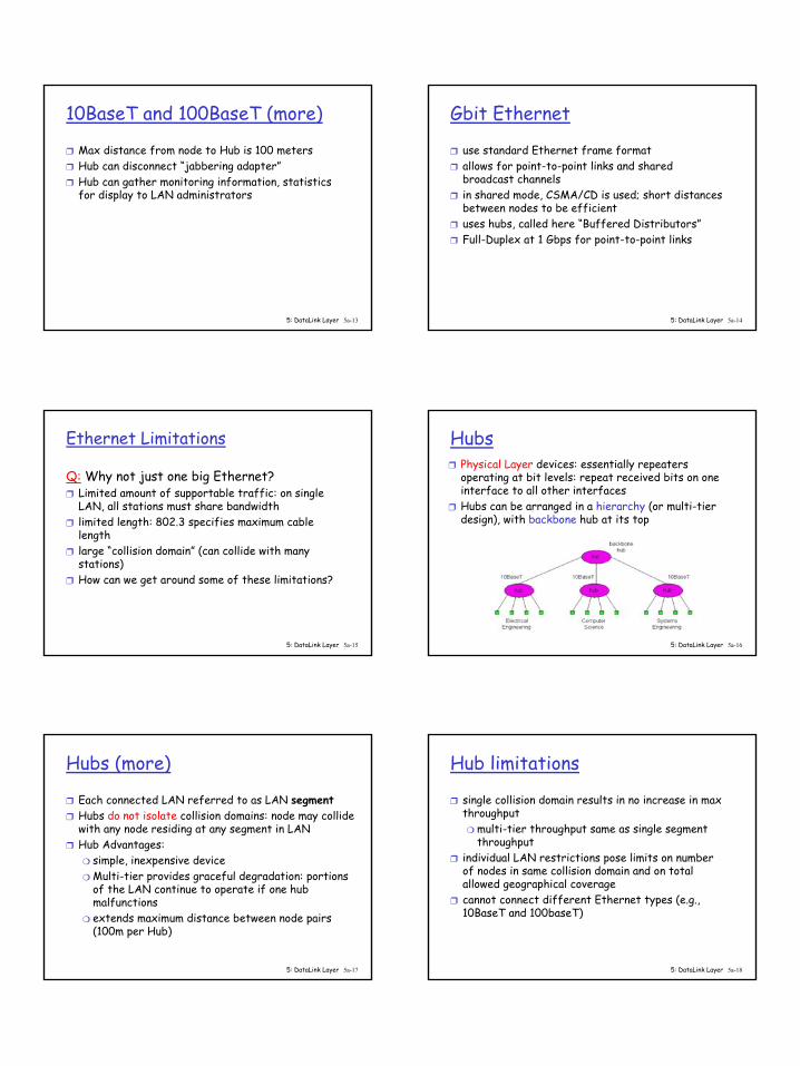
5: DataLink Layer 5a-22
Backbone Bridge
5: DataLink Layer 5a-23
Interconnection Without Backbone
❒ Not recommended for two reasons:- single point of failure at Computer Science hub- all traffic between EE and SE must path over
CS segment
5: DataLink Layer 5a-24
Bridge Filtering
❒ bridges learn which hosts can be reached through which interfaces: maintain filtering tables❍ when frame received, bridge “learns” location of
sender: incoming LAN segment❍ records sender location in filtering table
❒ filtering table entry: ❍ (Node LAN Address, Bridge Interface, Time Stamp)❍ stale entries in Filtering Table dropped (TTL can be
60 minutes)
5
5: DataLink Layer 5a-25
Bridge Filtering
❒ filtering procedure:if destination is on LAN on which frame was received
then drop the frameelse { lookup filtering table
if entry found for destinationthen forward the frame on interface indicated;else flood; /* forward on all but the interface
on which the frame arrived*/
}
5: DataLink Layer 5a-26
Bridge Learning: exampleSuppose C sends frame to D and D replies back with
frame to C
❒ C sends frame, bridge has no info about D, so floods to both LANs
❍ bridge notes that C is on port 1 ❍ frame ignored on upper LAN ❍ frame received by D
5: DataLink Layer 5a-27
Bridge Learning: example
❒ D generates reply to C, sends ❍ bridge sees frame from D ❍ bridge notes that D is on interface 2 ❍ bridge knows C on interface 1, so selectively
forwards frame out via interface 1
5: DataLink Layer 5a-28
Bridges Spanning Tree❒ for increased reliability, desirable to have
redundant, alternate paths from source to dest❒ with multiple simultaneous paths, cycles result -
bridges may multiply and forward frame forever❒ solution: organize bridges in a spanning tree by
disabling subset of interfacesDisabled
5: DataLink Layer 5a-29
Spanning Tree Algorithm
5: DataLink Layer 5a-30
Ethernet Switches
❒ Sophisticated bridges❍ Switches usually switch in
hardware, bridges in software
❍ large number of interfaces❒ Like bridges, layer 2
(frame) forwarding, filtering using LAN addresses
❒ Can support combinations of shared/dedicated, 10/100/1000 Mbps interfaces
6
5: DataLink Layer 5a-31
Switching
❒ Switching: A-to-B and A’-to-B’ simultaneously, no collisions
❒ cut-through switching: frame forwarded from input to output port without awaiting for assembly of entire frame❍ slight reduction in latency
❒ Store and forward switching: entire frame received before transmission out an output port
❒ Fragment-free switching: compromise, before send out the output port receive enough of the packet to do some error checking (ex. detect and drop partial frames)
5: DataLink Layer 5a-32
Common TopologyDedicated
Shared
5: DataLink Layer 5a-33
Bridges vs. Switches vs. Routers❒ Switches = sophisticated multi-port bridges❒ All store-and-forward devices
❒ Bridges/switches maintain filtering tables, implement filtering, learning and spanning tree algorithms
5: DataLink Layer 5a-34
Routers vs. Bridges
Bridges + and -+ Bridge operation is simpler requiring less
processing bandwidth- Topologies are restricted with bridges: a spanning
tree must be built to avoid cycles - Bridges do not offer protection from broadcast
storms (endless broadcasting by a host will be forwarded by a bridge)
5: DataLink Layer 5a-35
Routers vs. Bridges
Routers + and -+ arbitrary topologies can be supported, cycling is
limited by TTL counters (and good routing protocols)+ provide firewall protection against broadcast storms- require IP address configuration (not plug and play)- require higher processing bandwidth
❒ bridges do well in small (few hundred hosts) while routers used in large networks (thousands of hosts)
• BECN: congestion on reverse path• DE: discard eligibility
addressflags data CRC flags
12
5: DataLink Layer 5a-67
Frame Relay -VC Rate Control
❒ Committed Information Rate (CIR)❍ defined, “guaranteed” for each VC❍ negotiated at VC set up time❍ customer pays based on CIR
❒ DE bit: Discard Eligibility bit❍ Edge FR switch measures traffic rate for each
VC; marks DE bit❍ DE = 0: high priority, rate compliant frame;
deliver at “all costs”❍ DE = 1: low priority, eligible for discard when
congestion5: DataLink Layer 5a-68
LAN AddressesEach adapter on LAN has unique LAN address
5: DataLink Layer 5a-69
LAN Addresses vs IP Addresses32-bit IP address (128 bit IPv6):❒ network-layer address❒ used to get datagram to destination network
(recall IP network definition)LAN (or MAC or physical) address: ❒ used to get datagram from one interface to
another physically-connected interface (same network)
❒ 48 bit MAC address (for most LANs) burned in the adapter ROM
5: DataLink Layer 5a-70
LAN Address vs IP Addresses (more)❒ MAC address allocation administered by IEEE❒ manufacturer buys portion of MAC address space
(to assure uniqueness)❒ Analogy:
(a) MAC address: like Social Security Number(b) IP address: like postal address
❒ MAC flat address => portability ❍ can move LAN card from one LAN to another
❒ IP hierarchical address NOT portable❍ depends on network to which one attaches
5: DataLink Layer 5a-71
Recall earlier routing discussion
223.1.1.1
223.1.1.2
223.1.1.3
223.1.1.4 223.1.2.9
223.1.2.2
223.1.2.1
223.1.3.2223.1.3.1
223.1.3.27
A
BE
Starting at A, given IP datagram addressed to B:
❒ look up net. address of B, find B on same net. as A
❒ link layer send datagram to B inside link-layer frame
B’s MACaddr
A’s MACaddr
A’s IPaddr
B’s IPaddr IP payload
datagramframe
frame source,dest address
datagram source,dest address
5: DataLink Layer 5a-72
Question: How can we determine the MAC address of Bgiven B’s IP address?
13
5: DataLink Layer 5a-73
ARP: Address Resolution Protocol
❒ Each IP node (Host, Router) on LAN has ARP module, table
❒ ARP Table: IP/MAC address mappings for some LAN nodes
< IP address; MAC address; TTL>< ………………………….. >
❍ TTL (Time To Live): time after which address mapping will be forgotten (typically 20 min)
5: DataLink Layer 5a-74
ARP protocol❒ A knows B's IP address, wants to learn physical
address of B ❒ A broadcasts ARP query pkt, containing B's IP
address ❍ all machines on LAN receive ARP query
❒ B receives ARP packet, replies to A with its (B's) physical layer address
❒ A caches (saves) IP-to-physical address pairs until information becomes old (times out) ❍ soft state: information that times out (goes
away) unless refreshed
5: DataLink Layer 5a-75
Hands-on: arp
❒ arp ipaddress❍ Return the MAC address associated with the
given IP address❒ arp –a
❍ List the contents of the local ARP cache❒ arp –s hostname macAddress
❍ Used by the system administrator to add a specific entry to the local ARP cache
5: DataLink Layer 5a-76
ARP in ATM Nets
❒ ATM network needs destination ATM address❍ just like Ethernet needs destination Ethernet
address❒ IP/ATM address translation done by ATM ARP
(Address Resolution Protocol)❍ ARP server in ATM network performs
broadcast of ATM ARP translation request to all connected ATM devices
❍ hosts can register their ATM addresses with server to avoid lookup
5: DataLink Layer 5a-77
Routing to another LANwalkthrough: routing from A to B via R
❒ In routing table at source Host, find router 111.111.111.110
❒ In ARP table at source, find MAC address E6-E9-00-17-BB-4B, etc
A
RB
5: DataLink Layer 5a-78
❒ A creates IP packet with source A, destination B ❒ A uses ARP to get R’s physical layer address for 111.111.111.110❒ A creates Ethernet frame with R's physical address as dest,
Ethernet frame contains A-to-B IP datagram❒ A’s data link layer sends Ethernet frame ❒ R’s data link layer receives Ethernet frame ❒ R removes IP datagram from Ethernet frame, sees its
destined to B❒ R uses ARP to get B’s physical layer address ❒ R creates frame containing A-to-B IP datagram sends to B
A
RB
14
5: DataLink Layer 5a-79
Summary
❒ principles behind data link layer services:❍ error detection, correction❍ sharing a broadcast channel: multiple access❍ link layer addressing, ARP
❒ various link layer technologies❍ Ethernethubs, bridges, switches❍ IEEE 802.11 LANs❍ PPP❍ ATM, X.25, Frame Relay
❒ journey down the protocol stack now OVER!❍ Next stops: security, network management(?)