Link Layer 5-1 Link layer, LANs: outline 5.1 Introduction and services 5.2 Error detection and correction 5.3Multiple access protocols 5.4 Link-Layer Addressing 5.5 Ethernet 5.6 Link-layer switches 5.7 PPP 5.8 Link virtualization: MPLS 5.9 A day in the life of a web request
Transcript
Link Layer 5-1
Link layer LANs outline
51 Introduction and services
52 Error detection and correction
53Multiple access protocols
54 Link-Layer Addressing
55 Ethernet
56 Link-layer switches
57 PPP 58 Link
virtualization MPLS 59 A day in the life
of a web request
Link Layer 5-2
MAC addresses and ARP 32-bit IP address
network-layer address for interface used for layer 3 (network layer) forwarding
MAC (or LAN or physical or Ethernet) address function used lsquolocallyrdquo to get frame from one
interface to another physically-connected interface (same network in IP-addressing sense)
48 bit MAC address (for most LANs) burned in NIC ROM also sometimes software settable
MAC addresses and ARPeach adapter on LAN has unique MAC address
adapter
1A-2F-BB-76-09-AD
58-23-D7-FA-20-B0
0C-C4-11-6F-E3-98
71-65-F7-2B-08-53
LAN(wired orwireless)
Link Layer 5-4
LAN addresses (more) MAC address allocation administered by
IEEE manufacturer buys portion of MAC address
space (to assure uniqueness) analogy
MAC address like Social Security Number IP address like postal address
MAC flat address portability LAN card can be moved but its MAC address is
not changed Hierarchical IP address not portable
IP address depends on IP subnet to which node is attached
Link Layer 5-5
ARP address resolution protocol
ARP table each IP node (host router) on LAN has table
IPMAC address mappings for some LAN nodes
lt IP address MAC address TTLgt
TTL (Time To Live) time after which address mapping will be forgotten (typically 20 min)
Question how to determineinterfacersquos MAC address knowing its IP address
1A-2F-BB-76-09-AD
58-23-D7-FA-20-B0
0C-C4-11-6F-E3-98
71-65-F7-2B-08-53
LAN
137196723
137196778
137196714
137196788
Link Layer 5-6
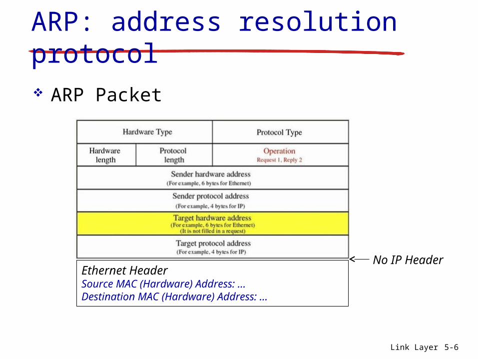
ARP address resolution protocol ARP Packet
Ethernet HeaderSource MAC (Hardware) Address hellipDestination MAC (Hardware) Address hellip
No IP Header
Link Layer 5-7
ARP protocol same LAN A wants to send datagram to
B A does not know Brsquos MAC
addressbull Brsquos MAC address not in Arsquos ARP
table A broadcasts ARP query
packet containing Bs IP address dest MAC address = FF-FF-FF-
FF-FF-FF all nodes on LAN receive ARP
query B receives ARP packet
replies to A with its (Bs) MAC address frame sent to Arsquos MAC address
(unicast)
A caches (saves) IP-to-MAC address pair in its ARP table until information becomes old (times out) soft state information
that times out (goes away) unless refreshed
ARP is ldquoplug-and-playrdquo nodes create their ARP
tables without intervention from net administrator
Link Layer 5-8
walkthrough send datagram from A to B via R focus on addressing ndash at IP (datagram) and MAC layer (frame) assume A knows Brsquos IP address assume A knows IP address of first hop router R (how) assume A knows Rrsquos MAC address (how)
Addressing routing to another LAN
R
1A-23-F9-CD-06-9B222222222220
111111111110E6-E9-00-17-BB-4BCC-49-DE-D0-AB-7D
111111111112
11111111111174-29-9C-E8-FF-55
A
22222222222249-BD-D2-C7-56-2A
22222222222188-B2-2F-54-1A-0F
B
R
1A-23-F9-CD-06-9B222222222220
111111111110E6-E9-00-17-BB-4BCC-49-DE-D0-AB-7D
111111111112
11111111111174-29-9C-E8-FF-55
A
22222222222249-BD-D2-C7-56-2A
22222222222188-B2-2F-54-1A-0F
B
Link Layer 5-9
Addressing routing to another LAN
IPEthPhy
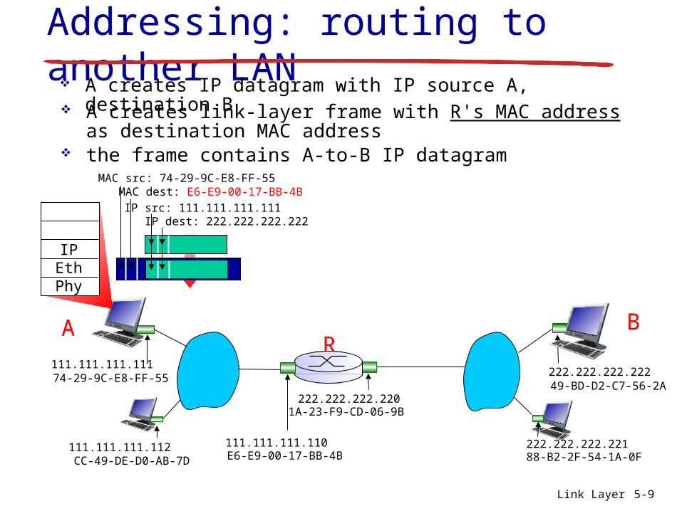
IP src 111111111111 IP dest 222222222222
A creates IP datagram with IP source A destination B A creates link-layer frame with Rs MAC address as
destination MAC address the frame contains A-to-B IP datagram
MAC src 74-29-9C-E8-FF-55 MAC dest E6-E9-00-17-BB-4B
R
1A-23-F9-CD-06-9B222222222220
111111111110E6-E9-00-17-BB-4BCC-49-DE-D0-AB-7D
111111111112
11111111111174-29-9C-E8-FF-55
A
22222222222249-BD-D2-C7-56-2A
22222222222188-B2-2F-54-1A-0F
B
Link Layer 5-10
Addressing routing to another LAN
IPEthPhy
frame sent from A to R
IPEthPhy
frame received at R datagram removed passed up to IP
MAC src 74-29-9C-E8-FF-55 MAC dest E6-E9-00-17-BB-4B
IP src 111111111111 IP dest 222222222222
IP src 111111111111 IP dest 222222222222
R
1A-23-F9-CD-06-9B222222222220
111111111110E6-E9-00-17-BB-4BCC-49-DE-D0-AB-7D
111111111112
11111111111174-29-9C-E8-FF-55
A
22222222222249-BD-D2-C7-56-2A
22222222222188-B2-2F-54-1A-0F
B
Link Layer 5-11
Addressing routing to another LAN
IP src 111111111111 IP dest 222222222222
R forwards datagram with IP source A destination B R creates link-layer frame with Bs MAC address as
destination MAC address the frame still contains A-to-B IP datagram
MAC src 1A-23-F9-CD-06-9B MAC dest 49-BD-D2-C7-56-2A
IPEthPhy
IPEthPhy
R
1A-23-F9-CD-06-9B222222222220
111111111110E6-E9-00-17-BB-4BCC-49-DE-D0-AB-7D
111111111112
11111111111174-29-9C-E8-FF-55
A
22222222222249-BD-D2-C7-56-2A
22222222222188-B2-2F-54-1A-0F
B
Link Layer 5-12
Addressing routing to another LAN
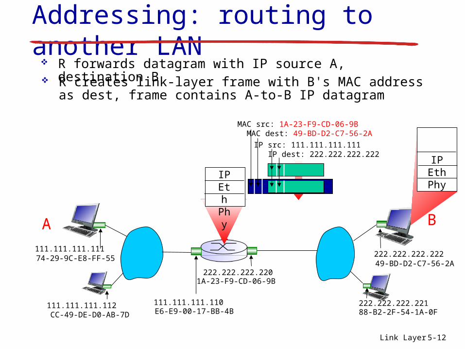
R forwards datagram with IP source A destination B R creates link-layer frame with Bs MAC address as dest
frame contains A-to-B IP datagram
IP src 111111111111 IP dest 222222222222
MAC src 1A-23-F9-CD-06-9B MAC dest 49-BD-D2-C7-56-2A
IPEthPhy
IPEthPhy
R
1A-23-F9-CD-06-9B222222222220
111111111110E6-E9-00-17-BB-4BCC-49-DE-D0-AB-7D
111111111112
11111111111174-29-9C-E8-FF-55
A
22222222222249-BD-D2-C7-56-2A
22222222222188-B2-2F-54-1A-0F
B
Link Layer 5-13
Addressing routing to another LAN
R forwards datagram with IP source A destination B R creates link-layer frame with Bs MAC address as dest
frame contains A-to-B IP datagram
IP src 111111111111 IP dest 222222222222
MAC src 1A-23-F9-CD-06-9B MAC dest 49-BD-D2-C7-56-2A
IPEthPhy
Link Layer 5-14
Link layer LANs outline
51 Introduction and services
52 Error detection and correction
53Multiple access protocols
54 Link-Layer Addressing
55 Ethernet
56 Link-layer switches
57 PPP 58 Link
virtualization MPLS 59 A day in the life
of a web request
Link Layer 5-15
Ethernetldquodominantrdquo wired LAN technology cheap $20 for NIC first widely used LAN technology simpler cheaper than token LANs and ATM kept up with speed race 10 Mbps ndash 10 Gbps
Metcalfersquos Ethernet sketch
Link Layer 5-16
Ethernet physical topology bus popular through mid 90s
all nodes in same collision domain (can collide with each other)
star prevails today active switch in center each ldquospokerdquo runs a (separate) Ethernet protocol
(nodes do not collide with each other)
switch
bus coaxial cablestar
Link Layer 5-17
Ethernet frame structure
sending adapter encapsulates IP datagram (or other network layer protocol packet) in Ethernet frame
preamble 7 bytes with pattern 10101010 hellip
10101011 used to synchronize receiver sender
clock rates
destaddress
sourceaddress
data (payload) CRCpreamble
type
Link Layer 5-18
Ethernet frame structure (more) addresses 6 byte source destination MAC
addresses if adapter receives frame with matching destination
address or with broadcast address (eg ARP packet) it passes data in frame to network layer protocol
otherwise adapter discards frame type indicates higher layer protocol (mostly IP
but others possible eg Novell IPX AppleTalk) CRC cyclic redundancy check at receiver
error detected frame is dropped
destaddress
sourceaddress
data (payload) CRCpreamble
type
Link Layer 5-19
Ethernet unreliable connectionless connectionless no handshaking between
sending and receiving NICs unreliable receiving NIC doesnrsquot send acks
or nacks to sending NIC data in dropped frames recovered only if
initial sender uses higher layer rdt (eg TCP) otherwise dropped data lost
Ethernetrsquos MAC protocol unslotted CSMACD wth exponential backoff
Link Layer 5-20
Ethernet CSMACD algorithm1 NIC receives datagram from network layer
creates frame
2-1 If NIC senses channel idle starts frame transmission
2-2 If NIC senses channel busy waits until channel idle then transmits
3 If NIC transmits entire frame without detecting another transmission NIC is done with frame
Link Layer 5-21
Ethernet CSMACD algorithm4 If NIC detects another transmission while
transmitting aborts and sends jam signal
5 After aborting NIC enters exponential backoff after mth collision NIC chooses K at random
from 012 hellip 2m-1 (m = minn10) NIC waits K512 bit times returns to Step 2 longer backoff interval with more collisions
5 DataLink Layer 5-22
Jam Signal make sure all other transmitters are aware of collision 48 bits
Bit time 1 microsec for 10 Mbps Ethernet for K=1023 wait time is about 50 msec
Exponential Backoff Goal adapt retransmission
attempts to estimated current load heavy load random
wait will be longer first collision choose K
from 01 delay is K 512 bit transmission times
after second collision choose K from 0123hellip
after ten collisions choose K from 01234hellip1023
Seeinteract with Javaapplet on AWL Web sitehighly recommended
Ethernet CSMACD algorithm (more)
Link Layer 5-23
CSMACD efficiency dprop = max propagation delay between 2 nodes in LAN dtrans = time to transmit max-size frame
efficiency goes to 1 as dprop goes to 0 as dtrans goes to infinity
better performance than ALOHA and simple cheap decentralized
transprop ddefficiency
5+1
1=
Link Layer 5-24
8023 Ethernet standards link amp physical layers
many different Ethernet standards common MAC protocol and frame format different speeds 2 Mbps 10 Mbps 100
Mbps 1Gbps 10G bps different physical layer media fiber cable
can learnconfigure each otherrsquos network address
simple
5 DataLink Layer 5-40
PPP non-requirements
no error correctionrecovery no flow control no order control
out of order delivery is allowed no need to support multipoint links
Error recovery flow control data re-ordering all delegated to higher layers
5 DataLink Layer 5-41
PPP Data Frame
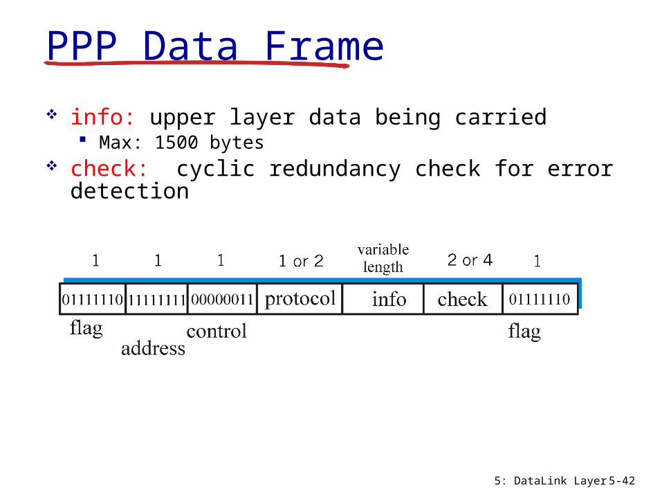
flag delimiter (framing) address always 11111111
does nothing control always 00000011
does nothing in the future possible control fields protocol upper layer protocol to which frame
delivered (eg PPP-LCP IP IPCP etc)
5 DataLink Layer 5-42
info upper layer data being carried Max 1500 bytes
check cyclic redundancy check for error detection
PPP Data Frame
5 DataLink Layer 5-43
PPP Data Control ProtocolBefore exchanging network-layer data data link
peers must LCP (Link Control Protocol)
configure PPP link (max frame length authentication)
IP Control Protocol (IPCP) learnconfigure network layer information for IP configurelearn IP address
Link Layer 5-44
Link layer LANs outline
51 Introduction and services
52 Error detection and correction
53Multiple access protocols
54 Link-Layer Addressing
55 Ethernet
56 Link-layer switches
57 PPP 58 Link
virtualization MPLS ( 생략 )
59 A day in the life of a web request
Link Layer 5-45
Link layer LANs outline
51 Introduction and services
52 Error detection and correction
53Multiple access protocols
54 Link-Layer Addressing
55 Ethernet
56 Link-layer switches
57 PPP 58 Link
virtualization MPLS 59 A day in the life
of a web request 2 학기 동안의 컴퓨터
네트워크 교과목 종합 리뷰
Link Layer 5-46
Synthesis a day in the life of a web request journey down protocol stack complete
application transport network link putting-it-all-together synthesis
goal identify review understand protocols (at all layers) involved in seemingly simple scenario requesting www page
scenario student attaches laptop to campus network requestsreceives wwwgooglecom
Link Layer 5-47
A day in the life scenario
Comcast network 68800013
Googlersquos network 64233160019 64233169105
web server
DNS server
school network 68802024
web page
browser
router(runs DHCP)
Link Layer 5-48
A day in the lifehellip connecting to the Internet
connecting laptop needs to get its own IP address addr of first-hop router addr of DNS server use DHCP
DHCPUDP
IPEthPhy
DHCP
DHCP
DHCP
DHCP
DHCP
DHCPUDP
IPEthPhy
DHCP
DHCP
DHCP
DHCPDHCP
DHCP request encapsulated in UDP encapsulated in IP encapsulated in 8023 Ethernet
Ethernet frame broadcast (dest FFFFFFFFFFFF) on LAN received at router running DHCP server Ethernet demuxed to IP demuxed UDP demuxed to DHCP
router(runs DHCP)
Link Layer 5-49
DHCP server formulates DHCP ACK containing clientrsquos IP address IP address of first-hop router for client name amp IP address of DNS server
DHCPUDP
IPEthPhy
DHCP
DHCP
DHCP
DHCP
DHCPUDP
IPEthPhy
DHCP
DHCP
DHCP
DHCP
DHCP
encapsulation at DHCP server frame forwarded (switch learning) through LAN demultiplexing at client
Client now has IP address knows name amp addr of DNS server IP address of its first-hop router
DHCP client receives DHCP ACK reply
A day in the lifehellip connecting to the Internet
router(runs DHCP)
Link Layer 5-50
A day in the lifehellip ARP (before DNS before HTTP)
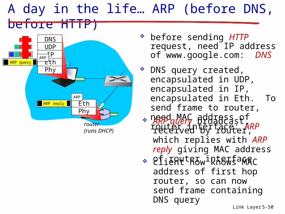
before sending HTTP request need IP address of wwwgooglecom DNS
DNSUDP
IPEthPhy
DNS
DNS
DNS
DNS query created encapsulated in UDP encapsulated in IP encapsulated in Eth To send frame to router need MAC address of router interface ARP
ARP query broadcast received by router which replies with ARP reply giving MAC address of router interface client now knows MAC address of first hop router so can now send frame containing DNS query
ARP query
EthPhy
ARP
ARP
ARP reply
router(runs DHCP)
Link Layer 5-51
DNSUDP
IPEthPhy
DNS
DNS
DNS
DNS
DNS
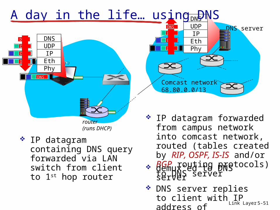
IP datagram containing DNS query forwarded via LAN switch from client to 1st hop router
IP datagram forwarded from campus network into comcast network routed (tables created by RIP OSPF IS-IS andor BGP routing protocols) to DNS server
demuxrsquoed to DNS server
DNS server replies to client with IP address of wwwgooglecom
Comcast network 68800013
DNS server
DNSUDP
IPEthPhy
DNS
DNS
DNS
DNS
A day in the lifehellip using DNS
router(runs DHCP)
Link Layer 5-52
A day in the lifehellipTCP connection carrying HTTP
HTTPTCPIP
EthPhy
HTTP
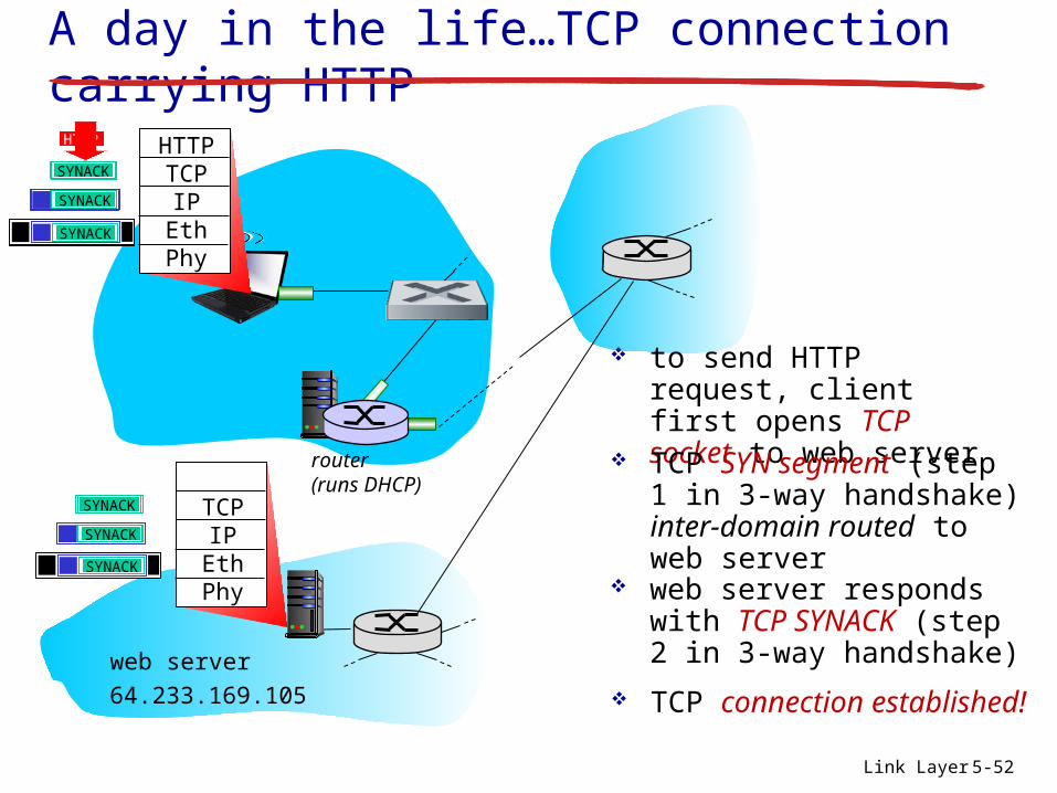
to send HTTP request client first opens TCP socket to web server
TCP SYN segment (step 1 in 3-way handshake) inter-domain routed to web server
TCP connection established
64233169105
web server
SYN
SYN
SYN
SYN
TCPIP
EthPhy
SYN
SYN
SYN
SYNACK
SYNACK
SYNACK
SYNACK
SYNACK
SYNACK
SYNACK
web server responds with TCP SYNACK (step 2 in 3-way handshake)
router(runs DHCP)
Link Layer 5-53
A day in the lifehellip HTTP requestreply
HTTPTCPIP
EthPhy
HTTP
HTTP request sent into TCP socket
IP datagram containing HTTP request routed to wwwgooglecom
IP datagram containing HTTP reply routed back to client
64233169105
web server
HTTPTCPIP
EthPhy
web server responds with HTTP reply (containing web page)
HTTP
HTTP
HTTPHTTP
HTTP
HTTP
HTTP
HTTP
HTTP
HTTP
HTTP
HTTP
HTTP
web page finally () displayed
Link Layer 5-54
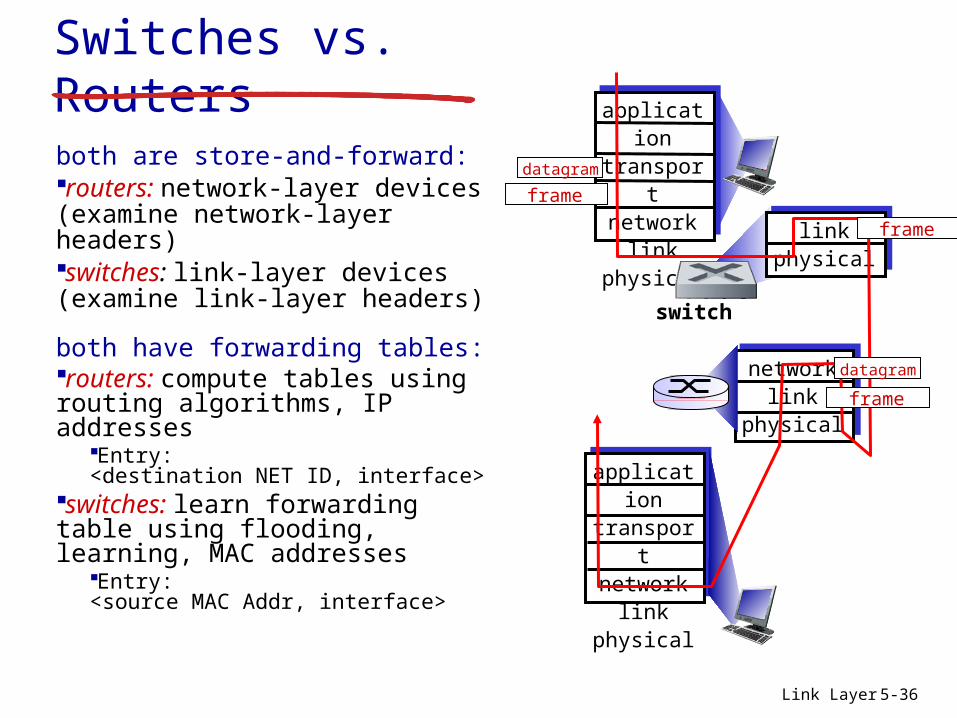
Chapter 5 Summary principles behind data link layer
services error detection correction sharing a broadcast channel multiple access link layer addressing
instantiation and implementation of various link layer technologies Ethernet switched LANS
synthesis a day in the life of a web request
Link Layer 5-55
Chapter 5 letrsquos take a breath journey down protocol stack complete
(except PHY) solid understanding of networking
principles practice hellip could stop here hellip but lots of
MAC addresses and ARPeach adapter on LAN has unique MAC address
adapter
1A-2F-BB-76-09-AD
58-23-D7-FA-20-B0
0C-C4-11-6F-E3-98
71-65-F7-2B-08-53
LAN(wired orwireless)
Link Layer 5-4
LAN addresses (more) MAC address allocation administered by
IEEE manufacturer buys portion of MAC address
space (to assure uniqueness) analogy
MAC address like Social Security Number IP address like postal address
MAC flat address portability LAN card can be moved but its MAC address is
not changed Hierarchical IP address not portable
IP address depends on IP subnet to which node is attached
Link Layer 5-5
ARP address resolution protocol
ARP table each IP node (host router) on LAN has table
IPMAC address mappings for some LAN nodes
lt IP address MAC address TTLgt
TTL (Time To Live) time after which address mapping will be forgotten (typically 20 min)
Question how to determineinterfacersquos MAC address knowing its IP address
1A-2F-BB-76-09-AD
58-23-D7-FA-20-B0
0C-C4-11-6F-E3-98
71-65-F7-2B-08-53
LAN
137196723
137196778
137196714
137196788
Link Layer 5-6
ARP address resolution protocol ARP Packet
Ethernet HeaderSource MAC (Hardware) Address hellipDestination MAC (Hardware) Address hellip
No IP Header
Link Layer 5-7
ARP protocol same LAN A wants to send datagram to
B A does not know Brsquos MAC
addressbull Brsquos MAC address not in Arsquos ARP
table A broadcasts ARP query
packet containing Bs IP address dest MAC address = FF-FF-FF-
FF-FF-FF all nodes on LAN receive ARP
query B receives ARP packet
replies to A with its (Bs) MAC address frame sent to Arsquos MAC address
(unicast)
A caches (saves) IP-to-MAC address pair in its ARP table until information becomes old (times out) soft state information
that times out (goes away) unless refreshed
ARP is ldquoplug-and-playrdquo nodes create their ARP
tables without intervention from net administrator
Link Layer 5-8
walkthrough send datagram from A to B via R focus on addressing ndash at IP (datagram) and MAC layer (frame) assume A knows Brsquos IP address assume A knows IP address of first hop router R (how) assume A knows Rrsquos MAC address (how)
Addressing routing to another LAN
R
1A-23-F9-CD-06-9B222222222220
111111111110E6-E9-00-17-BB-4BCC-49-DE-D0-AB-7D
111111111112
11111111111174-29-9C-E8-FF-55
A
22222222222249-BD-D2-C7-56-2A
22222222222188-B2-2F-54-1A-0F
B
R
1A-23-F9-CD-06-9B222222222220
111111111110E6-E9-00-17-BB-4BCC-49-DE-D0-AB-7D
111111111112
11111111111174-29-9C-E8-FF-55
A
22222222222249-BD-D2-C7-56-2A
22222222222188-B2-2F-54-1A-0F
B
Link Layer 5-9
Addressing routing to another LAN
IPEthPhy
IP src 111111111111 IP dest 222222222222
A creates IP datagram with IP source A destination B A creates link-layer frame with Rs MAC address as
destination MAC address the frame contains A-to-B IP datagram
MAC src 74-29-9C-E8-FF-55 MAC dest E6-E9-00-17-BB-4B
R
1A-23-F9-CD-06-9B222222222220
111111111110E6-E9-00-17-BB-4BCC-49-DE-D0-AB-7D
111111111112
11111111111174-29-9C-E8-FF-55
A
22222222222249-BD-D2-C7-56-2A
22222222222188-B2-2F-54-1A-0F
B
Link Layer 5-10
Addressing routing to another LAN
IPEthPhy
frame sent from A to R
IPEthPhy
frame received at R datagram removed passed up to IP
MAC src 74-29-9C-E8-FF-55 MAC dest E6-E9-00-17-BB-4B
IP src 111111111111 IP dest 222222222222
IP src 111111111111 IP dest 222222222222
R
1A-23-F9-CD-06-9B222222222220
111111111110E6-E9-00-17-BB-4BCC-49-DE-D0-AB-7D
111111111112
11111111111174-29-9C-E8-FF-55
A
22222222222249-BD-D2-C7-56-2A
22222222222188-B2-2F-54-1A-0F
B
Link Layer 5-11
Addressing routing to another LAN
IP src 111111111111 IP dest 222222222222
R forwards datagram with IP source A destination B R creates link-layer frame with Bs MAC address as
destination MAC address the frame still contains A-to-B IP datagram
MAC src 1A-23-F9-CD-06-9B MAC dest 49-BD-D2-C7-56-2A
IPEthPhy
IPEthPhy
R
1A-23-F9-CD-06-9B222222222220
111111111110E6-E9-00-17-BB-4BCC-49-DE-D0-AB-7D
111111111112
11111111111174-29-9C-E8-FF-55
A
22222222222249-BD-D2-C7-56-2A
22222222222188-B2-2F-54-1A-0F
B
Link Layer 5-12
Addressing routing to another LAN
R forwards datagram with IP source A destination B R creates link-layer frame with Bs MAC address as dest
frame contains A-to-B IP datagram
IP src 111111111111 IP dest 222222222222
MAC src 1A-23-F9-CD-06-9B MAC dest 49-BD-D2-C7-56-2A
IPEthPhy
IPEthPhy
R
1A-23-F9-CD-06-9B222222222220
111111111110E6-E9-00-17-BB-4BCC-49-DE-D0-AB-7D
111111111112
11111111111174-29-9C-E8-FF-55
A
22222222222249-BD-D2-C7-56-2A
22222222222188-B2-2F-54-1A-0F
B
Link Layer 5-13
Addressing routing to another LAN
R forwards datagram with IP source A destination B R creates link-layer frame with Bs MAC address as dest
frame contains A-to-B IP datagram
IP src 111111111111 IP dest 222222222222
MAC src 1A-23-F9-CD-06-9B MAC dest 49-BD-D2-C7-56-2A
IPEthPhy
Link Layer 5-14
Link layer LANs outline
51 Introduction and services
52 Error detection and correction
53Multiple access protocols
54 Link-Layer Addressing
55 Ethernet
56 Link-layer switches
57 PPP 58 Link
virtualization MPLS 59 A day in the life
of a web request
Link Layer 5-15
Ethernetldquodominantrdquo wired LAN technology cheap $20 for NIC first widely used LAN technology simpler cheaper than token LANs and ATM kept up with speed race 10 Mbps ndash 10 Gbps
Metcalfersquos Ethernet sketch
Link Layer 5-16
Ethernet physical topology bus popular through mid 90s
all nodes in same collision domain (can collide with each other)
star prevails today active switch in center each ldquospokerdquo runs a (separate) Ethernet protocol
(nodes do not collide with each other)
switch
bus coaxial cablestar
Link Layer 5-17
Ethernet frame structure
sending adapter encapsulates IP datagram (or other network layer protocol packet) in Ethernet frame
preamble 7 bytes with pattern 10101010 hellip
10101011 used to synchronize receiver sender
clock rates
destaddress
sourceaddress
data (payload) CRCpreamble
type
Link Layer 5-18
Ethernet frame structure (more) addresses 6 byte source destination MAC
addresses if adapter receives frame with matching destination
address or with broadcast address (eg ARP packet) it passes data in frame to network layer protocol
otherwise adapter discards frame type indicates higher layer protocol (mostly IP
but others possible eg Novell IPX AppleTalk) CRC cyclic redundancy check at receiver
error detected frame is dropped
destaddress
sourceaddress
data (payload) CRCpreamble
type
Link Layer 5-19
Ethernet unreliable connectionless connectionless no handshaking between
sending and receiving NICs unreliable receiving NIC doesnrsquot send acks
or nacks to sending NIC data in dropped frames recovered only if
initial sender uses higher layer rdt (eg TCP) otherwise dropped data lost
Ethernetrsquos MAC protocol unslotted CSMACD wth exponential backoff
Link Layer 5-20
Ethernet CSMACD algorithm1 NIC receives datagram from network layer
creates frame
2-1 If NIC senses channel idle starts frame transmission
2-2 If NIC senses channel busy waits until channel idle then transmits
3 If NIC transmits entire frame without detecting another transmission NIC is done with frame
Link Layer 5-21
Ethernet CSMACD algorithm4 If NIC detects another transmission while
transmitting aborts and sends jam signal
5 After aborting NIC enters exponential backoff after mth collision NIC chooses K at random
from 012 hellip 2m-1 (m = minn10) NIC waits K512 bit times returns to Step 2 longer backoff interval with more collisions
5 DataLink Layer 5-22
Jam Signal make sure all other transmitters are aware of collision 48 bits
Bit time 1 microsec for 10 Mbps Ethernet for K=1023 wait time is about 50 msec
Exponential Backoff Goal adapt retransmission
attempts to estimated current load heavy load random
wait will be longer first collision choose K
from 01 delay is K 512 bit transmission times
after second collision choose K from 0123hellip
after ten collisions choose K from 01234hellip1023
Seeinteract with Javaapplet on AWL Web sitehighly recommended
Ethernet CSMACD algorithm (more)
Link Layer 5-23
CSMACD efficiency dprop = max propagation delay between 2 nodes in LAN dtrans = time to transmit max-size frame
efficiency goes to 1 as dprop goes to 0 as dtrans goes to infinity
better performance than ALOHA and simple cheap decentralized
transprop ddefficiency
5+1
1=
Link Layer 5-24
8023 Ethernet standards link amp physical layers
many different Ethernet standards common MAC protocol and frame format different speeds 2 Mbps 10 Mbps 100
Mbps 1Gbps 10G bps different physical layer media fiber cable
can learnconfigure each otherrsquos network address
simple
5 DataLink Layer 5-40
PPP non-requirements
no error correctionrecovery no flow control no order control
out of order delivery is allowed no need to support multipoint links
Error recovery flow control data re-ordering all delegated to higher layers
5 DataLink Layer 5-41
PPP Data Frame
flag delimiter (framing) address always 11111111
does nothing control always 00000011
does nothing in the future possible control fields protocol upper layer protocol to which frame
delivered (eg PPP-LCP IP IPCP etc)
5 DataLink Layer 5-42
info upper layer data being carried Max 1500 bytes
check cyclic redundancy check for error detection
PPP Data Frame
5 DataLink Layer 5-43
PPP Data Control ProtocolBefore exchanging network-layer data data link
peers must LCP (Link Control Protocol)
configure PPP link (max frame length authentication)
IP Control Protocol (IPCP) learnconfigure network layer information for IP configurelearn IP address
Link Layer 5-44
Link layer LANs outline
51 Introduction and services
52 Error detection and correction
53Multiple access protocols
54 Link-Layer Addressing
55 Ethernet
56 Link-layer switches
57 PPP 58 Link
virtualization MPLS ( 생략 )
59 A day in the life of a web request
Link Layer 5-45
Link layer LANs outline
51 Introduction and services
52 Error detection and correction
53Multiple access protocols
54 Link-Layer Addressing
55 Ethernet
56 Link-layer switches
57 PPP 58 Link
virtualization MPLS 59 A day in the life
of a web request 2 학기 동안의 컴퓨터
네트워크 교과목 종합 리뷰
Link Layer 5-46
Synthesis a day in the life of a web request journey down protocol stack complete
application transport network link putting-it-all-together synthesis
goal identify review understand protocols (at all layers) involved in seemingly simple scenario requesting www page
scenario student attaches laptop to campus network requestsreceives wwwgooglecom
Link Layer 5-47
A day in the life scenario
Comcast network 68800013
Googlersquos network 64233160019 64233169105
web server
DNS server
school network 68802024
web page
browser
router(runs DHCP)
Link Layer 5-48
A day in the lifehellip connecting to the Internet
connecting laptop needs to get its own IP address addr of first-hop router addr of DNS server use DHCP
DHCPUDP
IPEthPhy
DHCP
DHCP
DHCP
DHCP
DHCP
DHCPUDP
IPEthPhy
DHCP
DHCP
DHCP
DHCPDHCP
DHCP request encapsulated in UDP encapsulated in IP encapsulated in 8023 Ethernet
Ethernet frame broadcast (dest FFFFFFFFFFFF) on LAN received at router running DHCP server Ethernet demuxed to IP demuxed UDP demuxed to DHCP
router(runs DHCP)
Link Layer 5-49
DHCP server formulates DHCP ACK containing clientrsquos IP address IP address of first-hop router for client name amp IP address of DNS server
DHCPUDP
IPEthPhy
DHCP
DHCP
DHCP
DHCP
DHCPUDP
IPEthPhy
DHCP
DHCP
DHCP
DHCP
DHCP
encapsulation at DHCP server frame forwarded (switch learning) through LAN demultiplexing at client
Client now has IP address knows name amp addr of DNS server IP address of its first-hop router
DHCP client receives DHCP ACK reply
A day in the lifehellip connecting to the Internet
router(runs DHCP)
Link Layer 5-50
A day in the lifehellip ARP (before DNS before HTTP)
before sending HTTP request need IP address of wwwgooglecom DNS
DNSUDP
IPEthPhy
DNS
DNS
DNS
DNS query created encapsulated in UDP encapsulated in IP encapsulated in Eth To send frame to router need MAC address of router interface ARP
ARP query broadcast received by router which replies with ARP reply giving MAC address of router interface client now knows MAC address of first hop router so can now send frame containing DNS query
ARP query
EthPhy
ARP
ARP
ARP reply
router(runs DHCP)
Link Layer 5-51
DNSUDP
IPEthPhy
DNS
DNS
DNS
DNS
DNS
IP datagram containing DNS query forwarded via LAN switch from client to 1st hop router
IP datagram forwarded from campus network into comcast network routed (tables created by RIP OSPF IS-IS andor BGP routing protocols) to DNS server
demuxrsquoed to DNS server
DNS server replies to client with IP address of wwwgooglecom
Comcast network 68800013
DNS server
DNSUDP
IPEthPhy
DNS
DNS
DNS
DNS
A day in the lifehellip using DNS
router(runs DHCP)
Link Layer 5-52
A day in the lifehellipTCP connection carrying HTTP
HTTPTCPIP
EthPhy
HTTP
to send HTTP request client first opens TCP socket to web server
TCP SYN segment (step 1 in 3-way handshake) inter-domain routed to web server
TCP connection established
64233169105
web server
SYN
SYN
SYN
SYN
TCPIP
EthPhy
SYN
SYN
SYN
SYNACK
SYNACK
SYNACK
SYNACK
SYNACK
SYNACK
SYNACK
web server responds with TCP SYNACK (step 2 in 3-way handshake)
router(runs DHCP)
Link Layer 5-53
A day in the lifehellip HTTP requestreply
HTTPTCPIP
EthPhy
HTTP
HTTP request sent into TCP socket
IP datagram containing HTTP request routed to wwwgooglecom
IP datagram containing HTTP reply routed back to client
64233169105
web server
HTTPTCPIP
EthPhy
web server responds with HTTP reply (containing web page)
HTTP
HTTP
HTTPHTTP
HTTP
HTTP
HTTP
HTTP
HTTP
HTTP
HTTP
HTTP
HTTP
web page finally () displayed
Link Layer 5-54
Chapter 5 Summary principles behind data link layer
services error detection correction sharing a broadcast channel multiple access link layer addressing
instantiation and implementation of various link layer technologies Ethernet switched LANS
synthesis a day in the life of a web request
Link Layer 5-55
Chapter 5 letrsquos take a breath journey down protocol stack complete
(except PHY) solid understanding of networking
principles practice hellip could stop here hellip but lots of
R forwards datagram with IP source A destination B R creates link-layer frame with Bs MAC address as dest
frame contains A-to-B IP datagram
IP src 111111111111 IP dest 222222222222
MAC src 1A-23-F9-CD-06-9B MAC dest 49-BD-D2-C7-56-2A
IPEthPhy
IPEthPhy
R
1A-23-F9-CD-06-9B222222222220
111111111110E6-E9-00-17-BB-4BCC-49-DE-D0-AB-7D
111111111112
11111111111174-29-9C-E8-FF-55
A
22222222222249-BD-D2-C7-56-2A
22222222222188-B2-2F-54-1A-0F
B
Link Layer 5-13
Addressing routing to another LAN
R forwards datagram with IP source A destination B R creates link-layer frame with Bs MAC address as dest
frame contains A-to-B IP datagram
IP src 111111111111 IP dest 222222222222
MAC src 1A-23-F9-CD-06-9B MAC dest 49-BD-D2-C7-56-2A
IPEthPhy
Link Layer 5-14
Link layer LANs outline
51 Introduction and services
52 Error detection and correction
53Multiple access protocols
54 Link-Layer Addressing
55 Ethernet
56 Link-layer switches
57 PPP 58 Link
virtualization MPLS 59 A day in the life
of a web request
Link Layer 5-15
Ethernetldquodominantrdquo wired LAN technology cheap $20 for NIC first widely used LAN technology simpler cheaper than token LANs and ATM kept up with speed race 10 Mbps ndash 10 Gbps
Metcalfersquos Ethernet sketch
Link Layer 5-16
Ethernet physical topology bus popular through mid 90s
all nodes in same collision domain (can collide with each other)
star prevails today active switch in center each ldquospokerdquo runs a (separate) Ethernet protocol
(nodes do not collide with each other)
switch
bus coaxial cablestar
Link Layer 5-17
Ethernet frame structure
sending adapter encapsulates IP datagram (or other network layer protocol packet) in Ethernet frame
preamble 7 bytes with pattern 10101010 hellip
10101011 used to synchronize receiver sender
clock rates
destaddress
sourceaddress
data (payload) CRCpreamble
type
Link Layer 5-18
Ethernet frame structure (more) addresses 6 byte source destination MAC
addresses if adapter receives frame with matching destination
address or with broadcast address (eg ARP packet) it passes data in frame to network layer protocol
otherwise adapter discards frame type indicates higher layer protocol (mostly IP
but others possible eg Novell IPX AppleTalk) CRC cyclic redundancy check at receiver
error detected frame is dropped
destaddress
sourceaddress
data (payload) CRCpreamble
type
Link Layer 5-19
Ethernet unreliable connectionless connectionless no handshaking between
sending and receiving NICs unreliable receiving NIC doesnrsquot send acks
or nacks to sending NIC data in dropped frames recovered only if
initial sender uses higher layer rdt (eg TCP) otherwise dropped data lost
Ethernetrsquos MAC protocol unslotted CSMACD wth exponential backoff
Link Layer 5-20
Ethernet CSMACD algorithm1 NIC receives datagram from network layer
creates frame
2-1 If NIC senses channel idle starts frame transmission
2-2 If NIC senses channel busy waits until channel idle then transmits
3 If NIC transmits entire frame without detecting another transmission NIC is done with frame
Link Layer 5-21
Ethernet CSMACD algorithm4 If NIC detects another transmission while
transmitting aborts and sends jam signal
5 After aborting NIC enters exponential backoff after mth collision NIC chooses K at random
from 012 hellip 2m-1 (m = minn10) NIC waits K512 bit times returns to Step 2 longer backoff interval with more collisions
5 DataLink Layer 5-22
Jam Signal make sure all other transmitters are aware of collision 48 bits
Bit time 1 microsec for 10 Mbps Ethernet for K=1023 wait time is about 50 msec
Exponential Backoff Goal adapt retransmission
attempts to estimated current load heavy load random
wait will be longer first collision choose K
from 01 delay is K 512 bit transmission times
after second collision choose K from 0123hellip
after ten collisions choose K from 01234hellip1023
Seeinteract with Javaapplet on AWL Web sitehighly recommended
Ethernet CSMACD algorithm (more)
Link Layer 5-23
CSMACD efficiency dprop = max propagation delay between 2 nodes in LAN dtrans = time to transmit max-size frame
efficiency goes to 1 as dprop goes to 0 as dtrans goes to infinity
better performance than ALOHA and simple cheap decentralized
transprop ddefficiency
5+1
1=
Link Layer 5-24
8023 Ethernet standards link amp physical layers
many different Ethernet standards common MAC protocol and frame format different speeds 2 Mbps 10 Mbps 100
Mbps 1Gbps 10G bps different physical layer media fiber cable
can learnconfigure each otherrsquos network address
simple
5 DataLink Layer 5-40
PPP non-requirements
no error correctionrecovery no flow control no order control
out of order delivery is allowed no need to support multipoint links
Error recovery flow control data re-ordering all delegated to higher layers
5 DataLink Layer 5-41
PPP Data Frame
flag delimiter (framing) address always 11111111
does nothing control always 00000011
does nothing in the future possible control fields protocol upper layer protocol to which frame
delivered (eg PPP-LCP IP IPCP etc)
5 DataLink Layer 5-42
info upper layer data being carried Max 1500 bytes
check cyclic redundancy check for error detection
PPP Data Frame
5 DataLink Layer 5-43
PPP Data Control ProtocolBefore exchanging network-layer data data link
peers must LCP (Link Control Protocol)
configure PPP link (max frame length authentication)
IP Control Protocol (IPCP) learnconfigure network layer information for IP configurelearn IP address
Link Layer 5-44
Link layer LANs outline
51 Introduction and services
52 Error detection and correction
53Multiple access protocols
54 Link-Layer Addressing
55 Ethernet
56 Link-layer switches
57 PPP 58 Link
virtualization MPLS ( 생략 )
59 A day in the life of a web request
Link Layer 5-45
Link layer LANs outline
51 Introduction and services
52 Error detection and correction
53Multiple access protocols
54 Link-Layer Addressing
55 Ethernet
56 Link-layer switches
57 PPP 58 Link
virtualization MPLS 59 A day in the life
of a web request 2 학기 동안의 컴퓨터
네트워크 교과목 종합 리뷰
Link Layer 5-46
Synthesis a day in the life of a web request journey down protocol stack complete
application transport network link putting-it-all-together synthesis
goal identify review understand protocols (at all layers) involved in seemingly simple scenario requesting www page
scenario student attaches laptop to campus network requestsreceives wwwgooglecom
Link Layer 5-47
A day in the life scenario
Comcast network 68800013
Googlersquos network 64233160019 64233169105
web server
DNS server
school network 68802024
web page
browser
router(runs DHCP)
Link Layer 5-48
A day in the lifehellip connecting to the Internet
connecting laptop needs to get its own IP address addr of first-hop router addr of DNS server use DHCP
DHCPUDP
IPEthPhy
DHCP
DHCP
DHCP
DHCP
DHCP
DHCPUDP
IPEthPhy
DHCP
DHCP
DHCP
DHCPDHCP
DHCP request encapsulated in UDP encapsulated in IP encapsulated in 8023 Ethernet
Ethernet frame broadcast (dest FFFFFFFFFFFF) on LAN received at router running DHCP server Ethernet demuxed to IP demuxed UDP demuxed to DHCP
router(runs DHCP)
Link Layer 5-49
DHCP server formulates DHCP ACK containing clientrsquos IP address IP address of first-hop router for client name amp IP address of DNS server
DHCPUDP
IPEthPhy
DHCP
DHCP
DHCP
DHCP
DHCPUDP
IPEthPhy
DHCP
DHCP
DHCP
DHCP
DHCP
encapsulation at DHCP server frame forwarded (switch learning) through LAN demultiplexing at client
Client now has IP address knows name amp addr of DNS server IP address of its first-hop router
DHCP client receives DHCP ACK reply
A day in the lifehellip connecting to the Internet
router(runs DHCP)
Link Layer 5-50
A day in the lifehellip ARP (before DNS before HTTP)
before sending HTTP request need IP address of wwwgooglecom DNS
DNSUDP
IPEthPhy
DNS
DNS
DNS
DNS query created encapsulated in UDP encapsulated in IP encapsulated in Eth To send frame to router need MAC address of router interface ARP
ARP query broadcast received by router which replies with ARP reply giving MAC address of router interface client now knows MAC address of first hop router so can now send frame containing DNS query
ARP query
EthPhy
ARP
ARP
ARP reply
router(runs DHCP)
Link Layer 5-51
DNSUDP
IPEthPhy
DNS
DNS
DNS
DNS
DNS
IP datagram containing DNS query forwarded via LAN switch from client to 1st hop router
IP datagram forwarded from campus network into comcast network routed (tables created by RIP OSPF IS-IS andor BGP routing protocols) to DNS server
demuxrsquoed to DNS server
DNS server replies to client with IP address of wwwgooglecom
Comcast network 68800013
DNS server
DNSUDP
IPEthPhy
DNS
DNS
DNS
DNS
A day in the lifehellip using DNS
router(runs DHCP)
Link Layer 5-52
A day in the lifehellipTCP connection carrying HTTP
HTTPTCPIP
EthPhy
HTTP
to send HTTP request client first opens TCP socket to web server
TCP SYN segment (step 1 in 3-way handshake) inter-domain routed to web server
TCP connection established
64233169105
web server
SYN
SYN
SYN
SYN
TCPIP
EthPhy
SYN
SYN
SYN
SYNACK
SYNACK
SYNACK
SYNACK
SYNACK
SYNACK
SYNACK
web server responds with TCP SYNACK (step 2 in 3-way handshake)
router(runs DHCP)
Link Layer 5-53
A day in the lifehellip HTTP requestreply
HTTPTCPIP
EthPhy
HTTP
HTTP request sent into TCP socket
IP datagram containing HTTP request routed to wwwgooglecom
IP datagram containing HTTP reply routed back to client
64233169105
web server
HTTPTCPIP
EthPhy
web server responds with HTTP reply (containing web page)
HTTP
HTTP
HTTPHTTP
HTTP
HTTP
HTTP
HTTP
HTTP
HTTP
HTTP
HTTP
HTTP
web page finally () displayed
Link Layer 5-54
Chapter 5 Summary principles behind data link layer
services error detection correction sharing a broadcast channel multiple access link layer addressing
instantiation and implementation of various link layer technologies Ethernet switched LANS
synthesis a day in the life of a web request
Link Layer 5-55
Chapter 5 letrsquos take a breath journey down protocol stack complete
(except PHY) solid understanding of networking
principles practice hellip could stop here hellip but lots of
R forwards datagram with IP source A destination B R creates link-layer frame with Bs MAC address as dest
frame contains A-to-B IP datagram
IP src 111111111111 IP dest 222222222222
MAC src 1A-23-F9-CD-06-9B MAC dest 49-BD-D2-C7-56-2A
IPEthPhy
Link Layer 5-14
Link layer LANs outline
51 Introduction and services
52 Error detection and correction
53Multiple access protocols
54 Link-Layer Addressing
55 Ethernet
56 Link-layer switches
57 PPP 58 Link
virtualization MPLS 59 A day in the life
of a web request
Link Layer 5-15
Ethernetldquodominantrdquo wired LAN technology cheap $20 for NIC first widely used LAN technology simpler cheaper than token LANs and ATM kept up with speed race 10 Mbps ndash 10 Gbps
Metcalfersquos Ethernet sketch
Link Layer 5-16
Ethernet physical topology bus popular through mid 90s
all nodes in same collision domain (can collide with each other)
star prevails today active switch in center each ldquospokerdquo runs a (separate) Ethernet protocol
(nodes do not collide with each other)
switch
bus coaxial cablestar
Link Layer 5-17
Ethernet frame structure
sending adapter encapsulates IP datagram (or other network layer protocol packet) in Ethernet frame
preamble 7 bytes with pattern 10101010 hellip
10101011 used to synchronize receiver sender
clock rates
destaddress
sourceaddress
data (payload) CRCpreamble
type
Link Layer 5-18
Ethernet frame structure (more) addresses 6 byte source destination MAC
addresses if adapter receives frame with matching destination
address or with broadcast address (eg ARP packet) it passes data in frame to network layer protocol
otherwise adapter discards frame type indicates higher layer protocol (mostly IP
but others possible eg Novell IPX AppleTalk) CRC cyclic redundancy check at receiver
error detected frame is dropped
destaddress
sourceaddress
data (payload) CRCpreamble
type
Link Layer 5-19
Ethernet unreliable connectionless connectionless no handshaking between
sending and receiving NICs unreliable receiving NIC doesnrsquot send acks
or nacks to sending NIC data in dropped frames recovered only if
initial sender uses higher layer rdt (eg TCP) otherwise dropped data lost
Ethernetrsquos MAC protocol unslotted CSMACD wth exponential backoff
Link Layer 5-20
Ethernet CSMACD algorithm1 NIC receives datagram from network layer
creates frame
2-1 If NIC senses channel idle starts frame transmission
2-2 If NIC senses channel busy waits until channel idle then transmits
3 If NIC transmits entire frame without detecting another transmission NIC is done with frame
Link Layer 5-21
Ethernet CSMACD algorithm4 If NIC detects another transmission while
transmitting aborts and sends jam signal
5 After aborting NIC enters exponential backoff after mth collision NIC chooses K at random
from 012 hellip 2m-1 (m = minn10) NIC waits K512 bit times returns to Step 2 longer backoff interval with more collisions
5 DataLink Layer 5-22
Jam Signal make sure all other transmitters are aware of collision 48 bits
Bit time 1 microsec for 10 Mbps Ethernet for K=1023 wait time is about 50 msec
Exponential Backoff Goal adapt retransmission
attempts to estimated current load heavy load random
wait will be longer first collision choose K
from 01 delay is K 512 bit transmission times
after second collision choose K from 0123hellip
after ten collisions choose K from 01234hellip1023
Seeinteract with Javaapplet on AWL Web sitehighly recommended
Ethernet CSMACD algorithm (more)
Link Layer 5-23
CSMACD efficiency dprop = max propagation delay between 2 nodes in LAN dtrans = time to transmit max-size frame
efficiency goes to 1 as dprop goes to 0 as dtrans goes to infinity
better performance than ALOHA and simple cheap decentralized
transprop ddefficiency
5+1
1=
Link Layer 5-24
8023 Ethernet standards link amp physical layers
many different Ethernet standards common MAC protocol and frame format different speeds 2 Mbps 10 Mbps 100
Mbps 1Gbps 10G bps different physical layer media fiber cable
can learnconfigure each otherrsquos network address
simple
5 DataLink Layer 5-40
PPP non-requirements
no error correctionrecovery no flow control no order control
out of order delivery is allowed no need to support multipoint links
Error recovery flow control data re-ordering all delegated to higher layers
5 DataLink Layer 5-41
PPP Data Frame
flag delimiter (framing) address always 11111111
does nothing control always 00000011
does nothing in the future possible control fields protocol upper layer protocol to which frame
delivered (eg PPP-LCP IP IPCP etc)
5 DataLink Layer 5-42
info upper layer data being carried Max 1500 bytes
check cyclic redundancy check for error detection
PPP Data Frame
5 DataLink Layer 5-43
PPP Data Control ProtocolBefore exchanging network-layer data data link
peers must LCP (Link Control Protocol)
configure PPP link (max frame length authentication)
IP Control Protocol (IPCP) learnconfigure network layer information for IP configurelearn IP address
Link Layer 5-44
Link layer LANs outline
51 Introduction and services
52 Error detection and correction
53Multiple access protocols
54 Link-Layer Addressing
55 Ethernet
56 Link-layer switches
57 PPP 58 Link
virtualization MPLS ( 생략 )
59 A day in the life of a web request
Link Layer 5-45
Link layer LANs outline
51 Introduction and services
52 Error detection and correction
53Multiple access protocols
54 Link-Layer Addressing
55 Ethernet
56 Link-layer switches
57 PPP 58 Link
virtualization MPLS 59 A day in the life
of a web request 2 학기 동안의 컴퓨터
네트워크 교과목 종합 리뷰
Link Layer 5-46
Synthesis a day in the life of a web request journey down protocol stack complete
application transport network link putting-it-all-together synthesis
goal identify review understand protocols (at all layers) involved in seemingly simple scenario requesting www page
scenario student attaches laptop to campus network requestsreceives wwwgooglecom
Link Layer 5-47
A day in the life scenario
Comcast network 68800013
Googlersquos network 64233160019 64233169105
web server
DNS server
school network 68802024
web page
browser
router(runs DHCP)
Link Layer 5-48
A day in the lifehellip connecting to the Internet
connecting laptop needs to get its own IP address addr of first-hop router addr of DNS server use DHCP
DHCPUDP
IPEthPhy
DHCP
DHCP
DHCP
DHCP
DHCP
DHCPUDP
IPEthPhy
DHCP
DHCP
DHCP
DHCPDHCP
DHCP request encapsulated in UDP encapsulated in IP encapsulated in 8023 Ethernet
Ethernet frame broadcast (dest FFFFFFFFFFFF) on LAN received at router running DHCP server Ethernet demuxed to IP demuxed UDP demuxed to DHCP
router(runs DHCP)
Link Layer 5-49
DHCP server formulates DHCP ACK containing clientrsquos IP address IP address of first-hop router for client name amp IP address of DNS server
DHCPUDP
IPEthPhy
DHCP
DHCP
DHCP
DHCP
DHCPUDP
IPEthPhy
DHCP
DHCP
DHCP
DHCP
DHCP
encapsulation at DHCP server frame forwarded (switch learning) through LAN demultiplexing at client
Client now has IP address knows name amp addr of DNS server IP address of its first-hop router
DHCP client receives DHCP ACK reply
A day in the lifehellip connecting to the Internet
router(runs DHCP)
Link Layer 5-50
A day in the lifehellip ARP (before DNS before HTTP)
before sending HTTP request need IP address of wwwgooglecom DNS
DNSUDP
IPEthPhy
DNS
DNS
DNS
DNS query created encapsulated in UDP encapsulated in IP encapsulated in Eth To send frame to router need MAC address of router interface ARP
ARP query broadcast received by router which replies with ARP reply giving MAC address of router interface client now knows MAC address of first hop router so can now send frame containing DNS query
ARP query
EthPhy
ARP
ARP
ARP reply
router(runs DHCP)
Link Layer 5-51
DNSUDP
IPEthPhy
DNS
DNS
DNS
DNS
DNS
IP datagram containing DNS query forwarded via LAN switch from client to 1st hop router
IP datagram forwarded from campus network into comcast network routed (tables created by RIP OSPF IS-IS andor BGP routing protocols) to DNS server
demuxrsquoed to DNS server
DNS server replies to client with IP address of wwwgooglecom
Comcast network 68800013
DNS server
DNSUDP
IPEthPhy
DNS
DNS
DNS
DNS
A day in the lifehellip using DNS
router(runs DHCP)
Link Layer 5-52
A day in the lifehellipTCP connection carrying HTTP
HTTPTCPIP
EthPhy
HTTP
to send HTTP request client first opens TCP socket to web server
TCP SYN segment (step 1 in 3-way handshake) inter-domain routed to web server
TCP connection established
64233169105
web server
SYN
SYN
SYN
SYN
TCPIP
EthPhy
SYN
SYN
SYN
SYNACK
SYNACK
SYNACK
SYNACK
SYNACK
SYNACK
SYNACK
web server responds with TCP SYNACK (step 2 in 3-way handshake)
router(runs DHCP)
Link Layer 5-53
A day in the lifehellip HTTP requestreply
HTTPTCPIP
EthPhy
HTTP
HTTP request sent into TCP socket
IP datagram containing HTTP request routed to wwwgooglecom
IP datagram containing HTTP reply routed back to client
64233169105
web server
HTTPTCPIP
EthPhy
web server responds with HTTP reply (containing web page)
HTTP
HTTP
HTTPHTTP
HTTP
HTTP
HTTP
HTTP
HTTP
HTTP
HTTP
HTTP
HTTP
web page finally () displayed
Link Layer 5-54
Chapter 5 Summary principles behind data link layer
services error detection correction sharing a broadcast channel multiple access link layer addressing
instantiation and implementation of various link layer technologies Ethernet switched LANS
synthesis a day in the life of a web request
Link Layer 5-55
Chapter 5 letrsquos take a breath journey down protocol stack complete
(except PHY) solid understanding of networking
principles practice hellip could stop here hellip but lots of
A day in the lifehellip connecting to the Internet
connecting laptop needs to get its own IP address addr of first-hop router addr of DNS server use DHCP
DHCPUDP
IPEthPhy
DHCP
DHCP
DHCP
DHCP
DHCP
DHCPUDP
IPEthPhy
DHCP
DHCP
DHCP
DHCPDHCP
DHCP request encapsulated in UDP encapsulated in IP encapsulated in 8023 Ethernet
Ethernet frame broadcast (dest FFFFFFFFFFFF) on LAN received at router running DHCP server Ethernet demuxed to IP demuxed UDP demuxed to DHCP
router(runs DHCP)
Link Layer 5-49
DHCP server formulates DHCP ACK containing clientrsquos IP address IP address of first-hop router for client name amp IP address of DNS server
DHCPUDP
IPEthPhy
DHCP
DHCP
DHCP
DHCP
DHCPUDP
IPEthPhy
DHCP
DHCP
DHCP
DHCP
DHCP
encapsulation at DHCP server frame forwarded (switch learning) through LAN demultiplexing at client
Client now has IP address knows name amp addr of DNS server IP address of its first-hop router
DHCP client receives DHCP ACK reply
A day in the lifehellip connecting to the Internet
router(runs DHCP)
Link Layer 5-50
A day in the lifehellip ARP (before DNS before HTTP)
before sending HTTP request need IP address of wwwgooglecom DNS
DNSUDP
IPEthPhy
DNS
DNS
DNS
DNS query created encapsulated in UDP encapsulated in IP encapsulated in Eth To send frame to router need MAC address of router interface ARP
ARP query broadcast received by router which replies with ARP reply giving MAC address of router interface client now knows MAC address of first hop router so can now send frame containing DNS query
ARP query
EthPhy
ARP
ARP
ARP reply
router(runs DHCP)
Link Layer 5-51
DNSUDP
IPEthPhy
DNS
DNS
DNS
DNS
DNS
IP datagram containing DNS query forwarded via LAN switch from client to 1st hop router
IP datagram forwarded from campus network into comcast network routed (tables created by RIP OSPF IS-IS andor BGP routing protocols) to DNS server
demuxrsquoed to DNS server
DNS server replies to client with IP address of wwwgooglecom
Comcast network 68800013
DNS server
DNSUDP
IPEthPhy
DNS
DNS
DNS
DNS
A day in the lifehellip using DNS
router(runs DHCP)
Link Layer 5-52
A day in the lifehellipTCP connection carrying HTTP
HTTPTCPIP
EthPhy
HTTP
to send HTTP request client first opens TCP socket to web server
TCP SYN segment (step 1 in 3-way handshake) inter-domain routed to web server
TCP connection established
64233169105
web server
SYN
SYN
SYN
SYN
TCPIP
EthPhy
SYN
SYN
SYN
SYNACK
SYNACK
SYNACK
SYNACK
SYNACK
SYNACK
SYNACK
web server responds with TCP SYNACK (step 2 in 3-way handshake)
router(runs DHCP)
Link Layer 5-53
A day in the lifehellip HTTP requestreply
HTTPTCPIP
EthPhy
HTTP
HTTP request sent into TCP socket
IP datagram containing HTTP request routed to wwwgooglecom
IP datagram containing HTTP reply routed back to client
64233169105
web server
HTTPTCPIP
EthPhy
web server responds with HTTP reply (containing web page)
HTTP
HTTP
HTTPHTTP
HTTP
HTTP
HTTP
HTTP
HTTP
HTTP
HTTP
HTTP
HTTP
web page finally () displayed
Link Layer 5-54
Chapter 5 Summary principles behind data link layer
services error detection correction sharing a broadcast channel multiple access link layer addressing
instantiation and implementation of various link layer technologies Ethernet switched LANS
synthesis a day in the life of a web request
Link Layer 5-55
Chapter 5 letrsquos take a breath journey down protocol stack complete
(except PHY) solid understanding of networking
principles practice hellip could stop here hellip but lots of