NTIA Report 92-289 Linking Protection in Federal Standard 1045 HF Radios Using the Data Encryption Standard Christopher Redding William J. Pomper U.S. DEPARTMENT OF COMMERCE Ronald H. Brown, Secretary Larry Irving, Assistant Secretary for Communications and Information December 1993
Transcript
NTIA Report 92-289
Linking Protection in Federal Standard 1045 HF Radios Using
the Data Encryption Standard
Christopher Redding William J. Pomper
U.S. DEPARTMENT OF COMMERCE Ronald H. Brown, Secretary
Larry Irving, Assistant Secretary
for Communications and Information
December 1993
iii
PREFACE The intent of this report is to describe a DES-based linking protection technique for potential standardization in Federal Standard 1049 Section 1. Federal Standard 1045 and Federal Standard 1049 Section 1 (linking protection) should be referenced for more specific description and implementation requirements.
v
CONTENTS
FIGURES...........................................................................................................................vii ABBREVIATIONS..........................................................................................................viii 1. INTRODUCTION ......................................................................................................... 1 2. ALE OVERVIEW.......................................................................................................... 2 2.1 Linking Process................................................................................................ 2 2.2 Data Link Layer ............................................................................................... 4 2.2.1 ALE Sublayer..................................................................................... 4 2.2.2 FEC Sublayer ..................................................................................... 5 2.2.3 Protection Sublayer ............................................................................ 5 2.3 Physical Layer.................................................................................................. 6 2.4 Receive Processing........................................................................................... 6 3. LINKING PROTECTION ............................................................................................. 7 3.1 Protection Interval Overview ........................................................................... 8 3.2 Linking Protection Requirements .................................................................... 8 4. A DES-BASED, 24-BIT, TIME-VARYING ELECTRONIC CODEBOOK ............... 9 4.1 Seed Word Format ......................................................................................... 11 4.1.1 Date Field ......................................................................................... 12 4.1.2 PI Field ............................................................................................. 12 4.1.3 Word Number Field ......................................................................... 13 4.1.4 Frequency Field................................................................................ 13 4.2 Word Number Field Rules of Operation........................................................ 13 5. LINKING PROTECTION TRANSMIT OPERATION.............................................. 15 5.1 Call Protocol................................................................................................... 15 5.1.1 Scanning Call ................................................................................... 16 5.1.2 Leading Call ..................................................................................... 18 5.1.3 Message Section............................................................................... 19 5.1.4 Conclusion........................................................................................ 23 5.1.5 Sound................................................................................................ 24 5.2 Response Protocol.......................................................................................... 24 5.3 Acknowledgement Protocol ........................................................................... 25 6. LINKING PROTECTION RECEIVER OPERATION............................................... 26 7. COMPUTATIONAL REQUIREMENTS ................................................................... 29
Figure 1. ALE three-way handshake ............................................................................... 3 Figure 2. Conceptual model of the ALE data link layer.................................................. 4 Figure 3. Receive data flow in an ALE system ............................................................... 7 Figure 4. DES-based, 24-bit, time-varying electronic codebook .................................. 10 Figure 5. The DALE function .......................................................................................... 11 Figure 6. 52-bit seed word format ................................................................................. 12 Figure 7. Transmitting station state diagram for a 2-section PI (DBM not shown)...... 15 Figure 8. Call protocol................................................................................................... 16 Figure 9. Individual call protocol .................................................................................. 17 Figure 10. Leading call section of protocol..................................................................... 18 Figure 11. AMD message section of protocol................................................................. 20 Figure 12. DTM message section of protocol ................................................................. 21 Figure 13. DBM message section of protocol ................................................................. 22 Figure 14. Encryption of the last 12-bit word of DBM message section........................ 23 Figure 15. Decryption of last 12-bit word of DBM message section.............................. 23 Figure 16. Response protocol .......................................................................................... 25 Figure 17. Acknowledgement protocol ........................................................................... 25 Figure 18. Receive dataflow in a protected ALE system ................................................ 26 Figure 19. Decryption required during word synchronization process ........................... 28 Figure 20. Receiving station state diagram for a 2-section PI (DBM not shown) .......... 28
viii
ABBREVIATIONS
ACK Acknowledgement ALE Automatic Link Establishment AMD Automatic Message Display ASCII American Standard Code for Information Interchange bps Bits Per Second CMOS Complimentary Metallic Oxide Semiconductor CRC Cyclic Redundancy Check CT Cipher Text DBM Data Block Mode DES Data Encryption Standard DTM Data Text Mode ECB Electronic Code Book FEC Forward Error Correction FIPS PUB Federal Information Processing Standard Publication FS Federal Standard FSK Frequency Shift Keying HF High Frequency Hz Hertz IC Integrated Circuit IV Initialization Vector kbps Kilobits per Second
ix
kHz Kilohertz LP Linking Protection LQA Link Quality Analysis LSB Least Significant Bit Mbps Megabits per Second MHz Megahertz MSB Most Significant Bit µs Microsecond ms Millisecond NIST National Institute of Standards and Technology NMOS N-channel Metallic Oxide Semiconductor PI Protection Interval PT Plain Text s Second TOD Time-Of-Day W Word number field XOR Exclusive-or
LINKING PROTECTION IN FEDERAL STANDARD 1045 HF RADIOS
USING THE DATA ENCRYPTION STANDARD
Christopher Redding and William J. Pomper*
A method of utilizing the Data Encryption Standard (DES) algorithm for
linking protection in HF radios complying with Federal Standard 1045 is
described. The unique DES encryption method, which permits a codebook
type of encryption of 24-bit words, is explained in detail. Also discussed is
the method used to integrate this encryption process with the Federal
Standard 1045 automatic link establishment protocols. Processing speed
requirements for the hardware and software used to implement this
scheme are explained, and available DES devices that can support the
described implementation are identified.
Key Words: authentication, automatic link establishment, ALE, codebook,
cryptographic, Data Encryption Standard, DES, decryption, encryption,
Federal Standard 1045, linking protection, LP.
1. INTRODUCTION
Federal Standard 1045 (FS-1045) (NCS, 1990) specifies the basic procedures and protocols
for high-frequency (HF) automatic link establishment (ALE) radios. ALE allows stations
to automatically and rapidly establish radio links, determine the best available channel,
and transfer digital orderwire messages. While ALE technology automates and
expedites the linking process, it also creates a potential vulnerability, i.e., stations may
respond to adversarial linking transmissions. These transmissions can be in the form of
* The authors are with the Institute for Telecommunication Sciences, National Telecommunications and Information Administration, U.S. Department of Commerce, Boulder, CO 80303.
2
an unauthorized caller imitating a legitimate ALE station or a simple play-back of a
previous transmission. In both scenarios, the true identity of the caller may not be
known; therefore, some form of authentication is needed. The protection mechanism that
has been developed, referred to as linking protection (LP), counters these unwanted
intrusions, and provides a measure of confidentiality to the ALE addressing and
orderwire message transmission. This report describes a technique employing the Data
Encryption Standard (DES) algorithm (NIST, 1988) to provide LP for the ALE signaling.
Additional information on this topic is given by Redding and Johnson (1991).
2. ALE OVERVIEW
ALE is a technique that permits radio stations to automatically initiate and establish HF
radio links. When directed, an ALE transmitter station can transmit on the best available
channel to a scanning receiver. In the ALE receive mode, the receiver scans a number
of frequencies. The receiver pauses and listens on each channel for incoming ALE
signals, and when an ALE signal is detected, it stops and listens to determine if the
transmission is intended for itself. ALE stations have the capability to perform a link
quality analysis, or LQA, which allows the best available channel to be selected for
communication. The capability also exists to embed digital text (orderwire) messages
within the ALE signaling.
2.1 Linking Process
The basic link establishment process is accomplished via a three-way handshake between
two stations. The three-way handshake consists of the call, response, and
acknowledgement, as shown in Figure 1. The calling station initiates the call by
transmitting a series of words containing a "TO" preamble and the called station's
address, and concludes with a word containing a "THIS IS" preamble and its own
address. Each "block" in Figure 1 consists of a single, coded 24-bit ALE word (Section
2.2 provides details of the coding). The called radio, which is typically scanning a
3
number of channels, stops on the channel on which it hears the call and decodes the
ALE words to determine if the call is intended for itself. If so, the called station answers
with a short response beginning with words containing a "TO" preamble and the address
of the calling station, and concludes by transmitting a word containing a THIS IS
preamble and its own address. When the original calling station receives the response,
it is assured of bilateral connectivity, and sends an acknowledgement to the called
station, thus completing the three-way handshake for establishing the link. The time
required for establishing a link is approximately 14 seconds (for stations scanning 10
channels at 2 channels per second). After a link has been established, the operator is
signaled, and voice or data communications can be initiated. Termination of a link is
accomplished by the transmission of a "return to scan" signal or by the use of an internal
timer, which automatically returns the receiver to the scan mode after a preset duration
of inactivity.
Figure 1. ALE three-way handshake (NCS, 1990).
The ALE protocol also has the capability to transfer digital information (i.e., LQA data
or orderwire messages). These messages can be inserted in anyone of the three message
sections of the ALE protocol, at the locations indicated by the "▼" symbol in Figure 1.
4
2.2 Data Link Layer
The FS-1045 ALE data link layer, shown in Figure 2, consists of three distinct sublayers:
the ALE protocol sublayer, the forward error correction (FEC) sublayer, and the optional
protection sublayer located between the two. Linking protection is placed between the
ALE and FEC sublayers so that the encryption process takes full advantage of the error-
correcting power of the FEC sublayer.
Figure 2. Conceptual model of the ALE data link layer (NCS, 1993).
2.2.1 ALE Sublayer
The ALE sublayer incorporates standard protocols for link establishment, LQA, and
digital orderwire message transmission. The fundamental building block of the ALE
protocol structure is the 24-bit ALE word. ALE words are automatically exchanged
between stations to establish links, determine the best channel, and exchange orderwire
messages. The 24-bit ALE word consists of a 3-bit preamble field and three 7-bit
5
character fields. The preamble field defines one of eight possible word types or
functions, identified as: TO, FROM, THIS IS, THIS WAS, THRU, COMMAND, DATA,
and REPEAT. Each character field specifies an ASCII character, which can be utilized
as an address designator or as text, depending on the preamble field.
2.2.2 FEC Sublayer
The FEC sublayer incorporates three error detection and correction techniques to support
improved linking capability over the often degraded HF channel. The transmitter
performs Golay encoding, interleaving, and triple redundancy, whereas the receiver
performs the reverse functions of majority voting, deinterleaving, and Golay decoding.
In the ALE transmitter, the 24-bit ALE word is first split into two 12-bit words with each
half being Golay encoded (24, 12, 3) to produce two 24-bit Golay words. Next, the two
24-bit words are interleaved, bit by bit, and a tone diversity bit is appended, producing a
49-bit word. The 49-bit word is then transmitted three times (via the physical layer) to
produce a 147-bit triple redundant word. Triple word redundancy allows some errors to
be corrected by employing 2-out-of-3 majority voting at the receiver.
At the ALE receiver, a received triple redundant word is input into the majority voter,
which produces a 49-bit word. After the tone diversity bit is discarded, a 48-bit word
remains, which is then deinterleaved into two 24-bit Golay words. Next, these two words
are delivered to the Golay decoders which attempt to recover two error-free halves of the
24-bit ALE word. After a 24-bit word has been recovered, it is then checked for valid
content in accordance with the ALE protocol.
2.2.3 Protection Sublayer
The protection sublayer performs two functions on the 24-bit ALE words: encryption and
decryption. In transmit operation, the plain text ALE words are input from the ALE
6
sublayer, encrypted, and passed on to the FEC sublayer. In receive operation, the reverse
function is performed: cipher text ALE words are input from the FEC sublayer,
decrypted, and passed on to the ALE sublayer. No additional bits are added to the 24-bit
ALE word by the protection sublayer (i.e., 24 input bits produce 24 output bits).
2.3 Physical Layer
At the physical layer, the ALE modem employs 8-ary FSK modulation with a tone
duration of 8 ms (125 baud). Each tone represents 3 bits of data and consists of one of
the following frequencies: 750, 1000, 1250, 1500, 1750, 2000, 2250, or 2500 Hz. The
resultant over-the-air data rate is 375 bits per second (bps).
2.4 Receive Processing
There are no synchronization bits used in the ALE protocol to indicate word
synchronization. Therefore, when an ALE signal is initially detected, the receiver
employs a series of tests to acquire word synchronization. The receiver attempts to
acquire synchronization by searching the received data stream for triple redundant word
boundaries, which occur every 392 ms. Word synchronization is determined by
employing a series of tests each time a new bit arrives at the receiver. Each new
received bit is shifted into the FEC sublayer, and the oldest bit is discarded, resulting in a
new 147-bit block (i.e., a block of the most recently received 147 bits is processed each
time a bit arrives). As shown in Figure 3, the majority voter conducts the first test,
which produces a candidate word when a specific number of unanimous votes is
exceeded. After the candidate word is deinterleaved into two 24-bit words, the Golay
decoders attempt to produce two 12-bit error-free words. If the errors contained in those
words are detectable and correctable, a candidate 24-bit word will be output (i.e., no
output will be produced if the words contain uncorrectable errors). Thirdly, the
candidate 24-bit word must be acceptable to the ALE protocol sublayer. In protected
receive operation, as described in Section 6, a decryption process is performed before
7
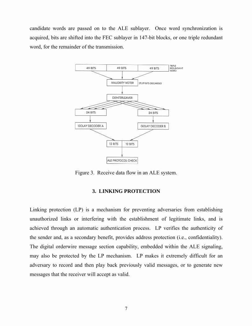
candidate words are passed on to the ALE sublayer. Once word synchronization is
acquired, bits are shifted into the FEC sublayer in 147-bit blocks, or one triple redundant
word, for the remainder of the transmission.
Figure 3. Receive data flow in an ALE system.
3. LINKING PROTECTION
Linking protection (LP) is a mechanism for preventing adversaries from establishing
unauthorized links or interfering with the establishment of legitimate links, and is
achieved through an automatic authentication process. LP verifies the authenticity of
the sender and, as a secondary benefit, provides address protection (i.e., confidentiality).
The digital orderwire message section capability, embedded within the ALE signaling,
may also be protected by the LP mechanism. LP makes it extremely difficult for an
adversary to record and then play back previously valid messages, or to generate new
messages that the receiver will accept as valid.
8
LP is produced by encrypting the ALE words before transmission and decrypting the
received ALE words. ALE transmissions are encrypted by the use of a cryptographic
algorithm (DES in this application), a key variable, and randomization data consisting
of a 52-bit seed word containing known time-of-day and the transmission channel
frequency information.
3.1 Protection Interval Overview
The time-based encryption concept prevents previously recorded ALE signals from being
accepted as valid by the LP receiver; therefore, calling ALE stations that employ LP are
authenticated by the decryption process at the receiver. The minimum time-of-day
increment or "window" that the encryption process employs is referred to as the
protection interval (PI). The interval is 2 seconds for this application. The PI information
that is used to vary the encryption process is contained in the seed word (discussed in
Section 4.1).
3.2 Linking Protection Requirements
Requirements for an LP mechanism have been developed by the HF radio standards
bodies and were adhered to when developing the DES approach. The principal
requirements, as outlined by Johnson (1991a) are described below.
A. The addition of LP shall not increase the time to establish a link or
significantly degrade the probability of linking over that of a non-protected
radio.
B. The addition of LP shall not add any synchronization bits or cryptographic
preambles to the ALE signal. This maintains the characteristic that a
protected receiver can acquire cryptographic (and word) synchronization
at any point in a transmission, the same as that for a receiver in an
unprotected system.
9
C. The LP mechanism shall provide a 24-bit error extension only within the
decrypted 24-bit ALE word that is being processed. This error extension
shall occur for changes in either the received cipher text, key variable, or
seed. The error extension shall not extend from one word to another.
D. The processing of the receive LP function must be performed in real time,
the same as that for non-protected systems.
4. A DES-BASED, 24-BIT, TIME-VARYING ELECTRONIC CODEBOOK
The linking protection technique described herein employs the DES algorithm in a time-
varying 24-bit electronic code book (ECB) mode as the basis for encrypting 24-bit ALE
words. The requirements for an LP algorithm (see Section 3.1) were observed when
developing the DES-based scheme. This method requires no "over-the-air"
synchronization bits and is compatible with the FS-1045 ALE protocols. It also meets the
requirement for error extension throughout the 24-bit ALE word.
The enciphering computation used to provide protection for each 24-bit ALE word is
diagrammed in Figure 4. As shown in the figure, a 24-bit plain text (PT) ALE word is
initially divided into two 12-bit blocks (L0 and R0). Bits 1-12 of the ALE word are
mapped into bits 1-12 of L0 and bits 13-24 of the ALE word are mapped into bits 1-12 of
R0. The function labeled DALE in Figure 4 is defined in Figure 5 and consists of single
DES encryption of a 64-bit input block. The input block is a concatenation of a 12-bit
word (either R0, R1, or R2) and the 52-bit seed word. Bits 1-12 of either R0, R1, or R2 are
mapped into the input block bits I1-I12 and bits 1-52 of the seed word are mapped into
the input block bits I13-I64 (the most significant bit (MSB) of the seed word becomes I13
and the least significant bit (LSB) of the seed word becomes I64). This encryption is
performed under a single DES key variable with the 52-bit seed word remaining constant
during the processing of an individual 24-bit ALE word. The encryption produces a
64-bit output block (O1-O64); bits O1-O12 are used in the exclusive-or (XOR)
10
function, and bits O13-O64 are discarded. As noted in Figure 4, the process requires that
the function DALE be invoked three times to complete the encryption of a 24-bit ALE
word. The XOR function in Figure 4 is a bit-for-bit modulo-2 addition of each of the bits
of L0, L1, or L2 with output block bits O1-O12 from the DALE function. Output blocks L3
and R3 form the cipher text (CT) ALE word. Bits 1-12 of L3 are mapped into bits 1-12 of
the ALE word, and bits 1-12 of R3 are mapped into bits 13-24 of the ALE word.
Figure 4. DES-based, 24-bit, time-varying
electronic codebook.
The decryption process is identical to the encryption process. Blocks L3 and R3, which
were output from the encryption process, simply become input blocks (i.e., L0 = L3 and
R0 = R3) to the identical process at the receiver. The function DALE, as shown in Figure 5,
is simply a standard DES ECB encryption process as defined in FIPS PUB 81 (NIST,
1980). Note that since DALE is invoked three times to encrypt a single 24-bit ALE word,
11
the 24-bit code book process requires three standard DES ECB encryption cycles to
complete encryption or decryption.
Figure 5. The DALE function.
4.1 Seed Word Format
The 24-bit DES encryption process uses a 52-bit seed word, analogous to an Initialization
Vector (IV) in DES terminology. The seed word consists of a 9-bit date field, a 17-bit
PI field, a 4-bit word number field, and a 22-bit frequency field. The date field and the
PI field are collectively referred to as the time-of-day (TOD) field. Figure 6 depicts the
seed word. Note that the MSB of the seed word is on the left.
12
Figure 6. 52-bit seed word format.
4.1.1 Date Field
The date field, consisting of a 4-bit subfield for the current month (1 for January through
12 for December) and a 5-bit subfield for the current day of the month (1 through 31), is
incremented in accordance with real time. The day subfield is incremented once each
day at midnight. When it reaches its maximum value for the current month, the next
increment will reset the day subfield to 1 and increment the month subfield by 1. When
the month subfield is incremented to its maximum value of 12, the next increment will
reset it to 1. For transmit use, the date field is non-decrementing. The receiver, though,
may repeatedly increment and decrement the date while acquiring word synchronization
at midnight.
4.1.2 PI Field
The PI field consists of an 11-bit coarse time subfield that counts minutes since midnight,
and a 6-bit fine time sub field that counts seconds within the current minute. The fine
time subfield is incremented in 2-second intervals, producing a fine time subfield that is
always an even integer. This 2-second increment is known as the PI. The fine time
subfield is incremented to reflect real time except when ALE words are actively being
transmitted (encrypted) or received (decrypted). During these periods, the fine time
13
subfield is incremented in collaboration with real time and the state of the word number
field, as described in Section 4.2. At midnight, the PI field (coarse and fine time
subfields) is reset to 0 and the date field is updated. For transmit use, the PI field is
non-decrementing. The receiver may repeatedly increment and decrement the PI while
acquiring word synchronization at midnight.
4.1.3 Word Number Field
The word number (W) field contains 4 bits and is used to count ALE words transmitted
within a PI. The maximum value of the W field for a 2-second PI is 5. Data Block Mode
(DBM) is a special case where the W field is incremented up to and including W = 15
(with subsequent reset to 0). See Section 4.2 for the word number field rules of
operation.
4.1.4 Frequency Field
The 22-bit frequency field consists of five 4-bit subfields and one 2-bit subfield. Each
subfield contains an integer representing the frequency of transmission (in MHz) with
100 Hz resolution. The maximum value of this field is 39.9999 MHz.
4.2 Word Number Field Rules of Operation
The word number field rules of operation are described as follows.
A. During the scanning call phase of a call, the calling station alternates
encryption of words using W = 0 and W = 1. The first word of the
scanning call uses either value of W (0 or 1) that produces W = 1 for the
last word of the scanning call. The TOD used during the scanning call will
change as required to keep pace with real time, except that the TOD field
will only be changed when W = 0 (i.e., words encrypted with W = 1 will
use the same TOD as the preceding word).
14
B. At the beginning of the leading call phase of a call, the first word will be
encrypted with W = 0 and the correct TOD for the time of transmission of
that word.
C. All succeeding words of the call (i.e., message sections, terminations) will
use incrementing word numbers up to and including W = 5, with the
exception of DBM where W is a maximum of 15. For the first word
following a word encrypted with W = 5 (or W = 15 for DBM), the TOD
will be incremented and W will be reset to 0.
D. Responses, acknowledgements, and return-to-scan transmissions will start
with W = 0 and the current TOD. The W field is incremented up to and
including W = 5 (or W = 15 for DBM). For the first word following a word
encrypted with W = 5, (or W = 15 for DBM) the TOD field will be
incremented and W reset to 0 (as described in paragraph C above).
E. Single-channel sounds are protected in the same manner as a single-channel
call. A single-channel call consists of a station calling a non-scanning
station (single channel) except the procedure begins as in a leading call (as
in paragraph B above). A multi-channel sound is treated in the same way
as a scanning call (as described in Section A).
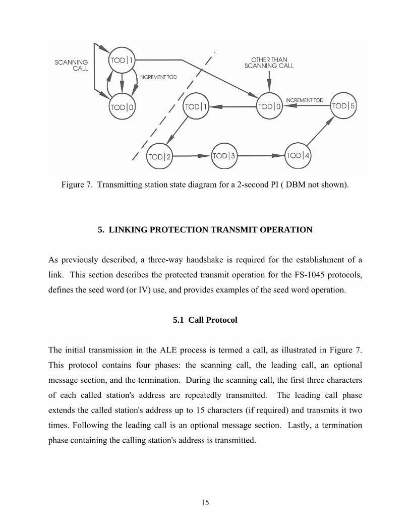
Figure 7 depicts the state diagram for permissible TOD and W combinations for a
2-second PI (maximum W field = 5) and the permissible sequences of these
combinations. As shown in the diagram, the TOD nomenclature indicates the TOD field,
and the W field value is indicated by the numerals following the "slash." DBM mode
(not shown in the diagram) is similar except that the maximum W field is 15.
15
Figure 7. Transmitting station state diagram for a 2-second PI ( DBM not shown).
5. LINKING PROTECTION TRANSMIT OPERATION
As previously described, a three-way handshake is required for the establishment of a
link. This section describes the protected transmit operation for the FS-1045 protocols,
defines the seed word (or IV) use, and provides examples of the seed word operation.
5.1 Call Protocol
The initial transmission in the ALE process is termed a call, as illustrated in Figure 7.
This protocol contains four phases: the scanning call, the leading call, an optional
message section, and the termination. During the scanning call, the first three characters
of each called station's address are repeatedly transmitted. The leading call phase
extends the called station's address up to 15 characters (if required) and transmits it two
times. Following the leading call is an optional message section. Lastly, a termination
phase containing the calling station's address is transmitted.
16
Figure 8. Call protocol.
5.1.1 Scanning Call
The scanning call phase of the call consists of a series of ALE words that are transmitted
repeatedly so that a scanning receiver is permitted enough time to scan all of its receive
frequencies and receive at least one of the transmitted words. For a station scanning
10 channels, the leading call word is transmitted 20 times. Only the first 3 characters of
each called station's address are transmitted during the scanning call phase. Additional
called station address characters, if needed, are transmitted in the leading call.
During the scanning call phase, the calling station alternates encryption of ALE words
using W = 0 and W = 1 in the seed word. The first word may use either value of
W (0 or 1). The TOD subfield (in the seed word) used during the scanning shall be
incremented as required to keep pace with real time, except that TOD will only change
when W = 0 (i.e., words encrypted with W = 1 will use the same TOD as the preceding
word).
Three types of scanning calls are specified in FS-1045: individual call, net call, and all
call/any call. Protected operation of each of these scanning calls is described in the
following section.
17
5.1.1.1 Individual Call
During the scanning call phase of an individual call, one 3-character address that
identifies a single station is transmitted repeatedly using the TO preamble. This 24-bit
word is encrypted using the current seed word with the W field alternating between
0 and 1, as shown in Figure 9. The TOD field tracks real time and changes accordingly,
with the exception that changes from one TOD to another are only permitted when
W = 0 (i.e., when W changes from 1 to 0). Within a PI, encryption of the same 24-bit
PT word results in the transmission of two different alternating CT words for the
duration of the 2-second PI. This is a consequence of using the same seed word for
every other encryption.
Figure 9. Individual call protocol.
5.1.1.2 Net Call
The net call is similar to the individual call; however, instead of a single address being
used to define a single station, a single address is used to define a prearranged group of
stations. PT words are encrypted in the same manner as the individual call.
18
5.1.1.3 All Call/Any Call
The all call/any call is similar to the individual call; however, instead of a single address
being used to define a single station, a single address is used to define all or any station.
PT words are encrypted in the same manner as the individual call.
5.1.2 Leading Call
The leading call phase of the call extends the address of the station being called to its
full length (up to 15 characters if required), as shown in Figure 10, and is repeated two
times using the TO/DATA/REPEAT preambles. The first word of the leading call is
encrypted with the current TOD and W = 0. For all succeeding words, the W field is
incremented up to and including a maximum of 5. The first word following a word
encrypted with W = 5 requires the TOD field to be incremented and W to be reset to 0.
This process is repeated for the remainder of the call. Therefore, each word of the
leading call is encrypted using a different seed word.
Figure 10. Leading call section of protocol.
19
5.1.3 Message Section
Orderwire messages and LQA data may be inserted in any one of the optional message
sections of the ALE protocol (i.e., call, response, or acknowledgement). The message
section, indicated by the "T" symbol in Figure 1 (see also Figure 8), can contain any one
of the following: LQA, Automatic Message Display (AMD), Data Text Message (DTM),
or Data Block Message (DBM) data. The three types of messages are described in the
following sections. LQA information can be inserted in the message section of the frame
by inserting a COMMAND LQA word. It is protected in the same manner as the
COMMAND words are for messages.
5.1.3.1 Automatic Message Display (AMD)
The AMD capability allows orderwire text messages using the expanded 64-character
ASCII subset data, specified in FS-1045, to be transferred between ALE stations. The
AMD protocol utilizes the three 7-bit fields within the ALE word as text characters.
Messages begin with the COMMAND AMD word (which contains the first three
characters of the AMD message) and then followed by remainder of the message section,
as shown in Figure 11. A single AMD message contains a maximum of 30 ALE words
(note that each word contains three ASCII characters). On the 30th AMD word, the
message can be extended for another 30 words by the use of the COMMAND AMD
word so that the maximum message is 59 words. The message section words alternate
DATA/REPEAT preambles.
The ALE words are encrypted as 24-bit blocks; therefore, the processing is transparent to
the LP encryption and decryption functions. The first word in the message section
continues the same TOD/W sequence as that in the leading call phase, as shown in
Figure 11. After a word has been encrypted with the maximum W field value of 5, the
W field will be reset to 0 and the TOD field incremented. Note that when entering the
20
message section, the W field can be any integer from 0 through 5. Each word of the
AMD message section is encrypted using a new seed word.
Figure 11. AMD message section of protocol.
5.1.3.2 Data Text Message (DTM)
The DTM mode enables stations to exchange full 128-character ASCII information or
unformatted data, as specified in FS-1045. DTM words consist of 24 bits and, therefore,
are encrypted and decrypted as 24-bit blocks.
The first DTM word in the message section is a 24-bit COMMAND DTM word that is
encrypted following the same TOD/W sequence as that in the leading call phase, as
shown in Figure 12. After a word has been encrypted with the maximum W field value
5, the W field will be reset to 0 and the TOD field incremented. This results in a new
seed word being used to encrypt each 24-bit DTM word. Note that when entering the
message section, the W field can be any integer from 0 through 5. The last word
contained in the DTM message section is a COMMAND CRC word, which comprises a
cyclic redundancy check (CRC).
21
Figure 12. DTM message section of protocol.
5.1.3.3 Data Block Message (DBM)
The DBM mode enables stations to transfer full 128-character ASCII information or
unformatted data, as specified in FS-1045. The DBM differs from the other orderwire
transfer modes in that information is transferred at a higher rate. This higher rate is due
to a change in how the FEC is applied. DBM data is deeply interleaved over the entire
variable-length DBM block and half-rate Golay encoded (24, 12, 3) as with typical ALE
words, but is not transmitted with triple redundancy. Rather, data is transmitted in
588-bit blocks, with the capability to send 445 of these blocks in extended DBM mode.
The entire DBM message (n data blocks) includes a single 16-bit CRC, embedded at the
end of the DBM message.
The first word in the DBM message section is a 24-bit COMMAND DBM word,
encrypted by continuing the same TOD/W sequence as that in the leading call phase,
shown in Figure 13. The DBM data block, which contains an integral number of 12-bit
words, starts after the COMMAND DBM word and also follows the same TOD/W
sequence for encryption. The 12-bit words are encrypted in pairs (i.e., 24-bit blocks)
with the W field incremented after each pair of 12-bit words is encrypted. The
maximum W field value is 15, so a new seed word is used each time a pair of 12-bit
22
Figure 13. DBM message section of protocol.
DBM words are encrypted. When a word has been encrypted with the maximum W field
value 15, the W field will be reset to 0 and the TOD field incremented. Note that when
entering the DBM message section, the W field can be any integer from 0 through 5. For
all words following the DBM mode (i.e., when transitioning out of the DBM mode into
the conclusion phase), the W field will be reset to 0 and the TOD field incremented.
When a DBM data block contains an odd number of 12-bit words, the last single 12-bit
word can be encrypted differently. First, a 12-bit field consisting of all ones is appended
to the current 52-bit seed word with the resultant 64 bits being encrypted using the DALE
Figure 14. Encryption of the last 12-bit word of DBM message section.
23
function. The 12 LSBs of the output block are then XOR'd with the last 12-bit word, as
shown in Figure 14. The output of the XOR function forms the encrypted 12-bit word.
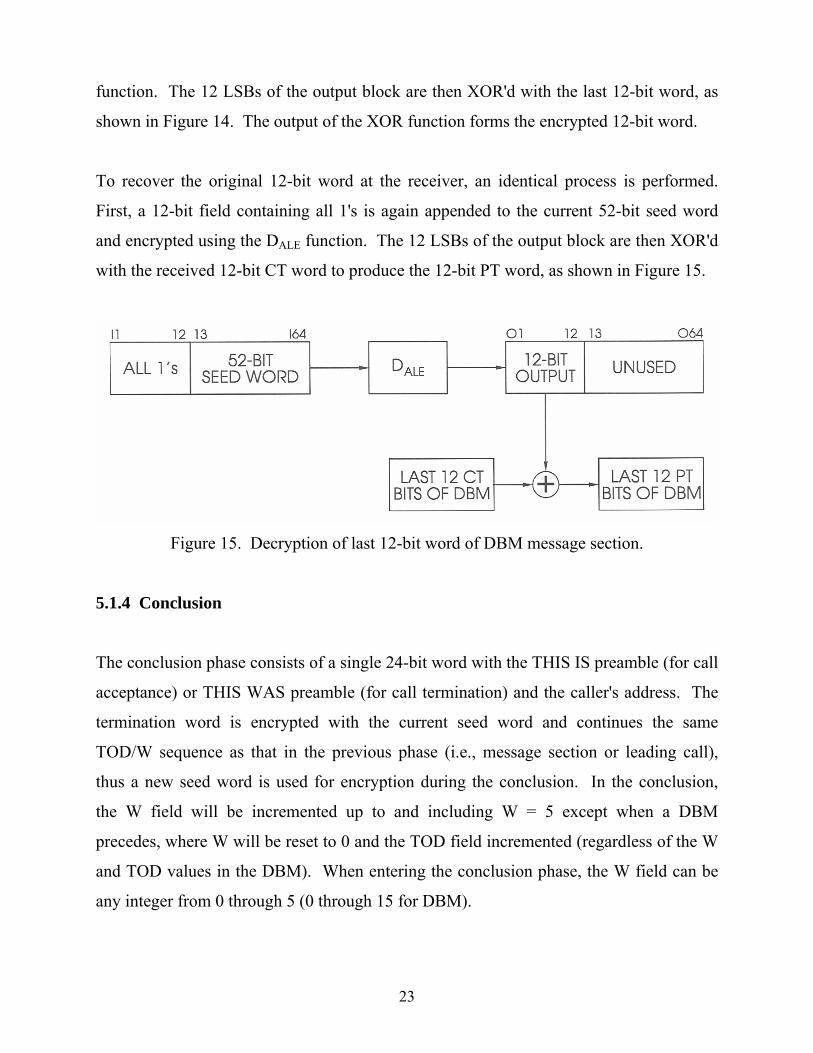
To recover the original 12-bit word at the receiver, an identical process is performed.
First, a 12-bit field containing all 1's is again appended to the current 52-bit seed word
and encrypted using the DALE function. The 12 LSBs of the output block are then XOR'd
with the received 12-bit CT word to produce the 12-bit PT word, as shown in Figure 15.
Figure 15. Decryption of last 12-bit word of DBM message section.
5.1.4 Conclusion
The conclusion phase consists of a single 24-bit word with the THIS IS preamble (for call
acceptance) or THIS WAS preamble (for call termination) and the caller's address. The
termination word is encrypted with the current seed word and continues the same
TOD/W sequence as that in the previous phase (i.e., message section or leading call),
thus a new seed word is used for encryption during the conclusion. In the conclusion,
the W field will be incremented up to and including W = 5 except when a DBM
precedes, where W will be reset to 0 and the TOD field incremented (regardless of the W
and TOD values in the DBM). When entering the conclusion phase, the W field can be
any integer from 0 through 5 (0 through 15 for DBM).
24
5.1.5 Sound
A sound consists of a single transmission with either the THIS IS or THIS WAS
preamble and the caller's address (up to 15 characters). A sound with the THIS IS
preamble requests a response, whereas a sound with a THIS WAS preamble does not.
Single-channel sounds are encrypted in the same manner as a single-channel call starting
with the current TOD and W = 0. All succeeding words of the sound are encrypted
using incrementing W values up to and including 5, which results in a new seed word
being used for each encryption. The following word will reset the W field to 0 and
increment the TOD field.
A multiple-channel sound is treated the same way as a scanning call where the calling
station alternates encryption of words using W = 0 and 1 with subsequent TOD
increment.
5.2 Response Protocol
The response is the second transmission in the three-way handshake and is sent from the
called station to the calling station. It consists of two repetitions (up to 15 characters in
each) of the called station's address plus an additional word containing a THIS IS
preamble with the called station's address. As shown in Figure 16, the start of each
response is encrypted with the current TOD and W = 0, with W being incremented to its
maximum of 5, and subsequent TOD rollover.
Therefore, each word of the response is encrypted using a new seed. Messages can be
inserted in the optional message section and are encrypted as described in Section 5.1.3.
25
Figure 16. Response protocol.
5.3 Acknowledgement Protocol
The acknowledgement is the third transmission in the link establishment process. It is
sent from the calling station to the called station and consists of two repetitions (up to
15 characters in each) of the called station's address plus a word containing a THIS IS
preamble with the calling station's address. The first word of the acknowledgement is
encrypted with the current TOD and W = 0, with the exception that the TOD that ended
the Call protocol cannot be reused. W is incremented for each subsequent word, as
shown in Figure 17. A different seed word is used to encrypt each of the 24-bit words
of the acknowledgement. Messages can be inserted in the optional message section and
are encrypted as described in Section 5.1.3.
Figure 17. Acknowledgement protocol.
26
6. LINKING PROTECTION RECEIVE OPERATION
As described in Section 2.4, there are no synchronization bits used in the ALE protocol
to indicate word synchronization. In protected operation, there are also no
synchronization bits or cryptographic preambles, so the receiver is still required to
employ a series of tests to acquire word synchronization. The receiver attempts to
acquire synchronization by searching the received data stream for triple redundant word
boundaries, which occur at 392-ms intervals. Word synchronization is determined by
employing a series of tests each time a new bit arrives at the receiver. Each new
received bit is shifted into the FEC sublayer and the oldest bit is discarded, resulting in
a new 147-bit block (i.e., a block of the most recently received 147 bits is processed each
time a bit arrives). As illustrated in Figure 18 , the potential triple redundant word is
Figure 18. Receive dataflow in a protected ALE system (Redding and Johnson, 1991).
27
input into the majority voter which produces a 49-bit candidate word whenever a
specific number of unanimous votes is exceeded. If a candidate word is produced, the
tone diversity bit is discarded, and a 48-bit word remains which is then deinterleaved
into two 24-bit words. The two words are then delivered to the Golay decoders which
yield two 12-bit words. An acceptable 24-bit candidate word consists of two 12-bit error-
free words which are output at intervals corresponding to the Golay decoder's error
correction setting. On average during word synchronization acquisition, a candidate
24-bit word is produced once every 8 ms when the Golay decoders are set to correct
3 errors per 12-bit word, once every 40 ms when set to correct 2 errors, or once every
78ms when set to correct 1 error, as described by Johnson (1991b). The peak speed that
will be encountered is one 24-bit candidate word per 2.67 ms (i.e., each time a new
received bit is shifted into the FEC sublayer). A decryption process (described in the
following paragraph) is performed on each candidate 24-bit word. Lastly, the candidate
24-bit word is passed on to the ALE protocol sublayer and checked for valid contents in
accordance with the ALE protocol (i.e., valid preamble, ASCII character subset, and
sequence). Once word synchronization has been acquired, bits are shifted into the FEC
sublayer in 147-bit blocks (i.e., one triple redundant word) for the remainder of the
transmission, or until synchronization is lost.
When the FEC sublayer passes the candidate CT word to the protection sublayer, it is
decrypted using the current key variable and seed information. However, due to time
inaccuracies which may exist between stations, the receive synchronization process is
complicated by the possibility that the received CT word may have been encrypted
using a different TOD and/or W combination than the current one at the receiver. This
potential difference requires the decryption of each candidate word using all allowed
seed words including the current and adjacent (future and past) seed words with W = 0
and 1, for a total of 6 decryptions. If the receiver is programmed to accept a special
feature called time requests, then the LP module must also attempt to decrypt words
using a coarse TOD (for the current minute only) with W = 0 and 1 (resulting in
2 additional decryptions). Therefore, during the word synchronization phase, the LP
28
module may be required to perform 8 decryptions on each potential 24-bit word, or
8 decryptions per bit time of 2.67 ms, as shown in Figure 19. This equates to a
decryption speed requirement of 333 µs.
Figure 19. Decryption required during word synchronization process.
Once word synchronization has been established, the number of decryptions required
per word time is greatly reduced since words are passed on to the LP module only on
triple redundant word boundaries, or every 392 ms. In word synchronization, decrypted
words must also be analyzed for correct TOD/W sequence, thus allowing the receiver to
maintain word synchronization. The allowed TOD/W sequences for the receiver are
shown in Figure 20. Receiving stations will also not accept more than one transmission
under a given PI (i.e., 2 s).
Figure 20. Receiving station state diagram for a 2- second PI (DBM not shown).
29
7. COMPUTATIONAL REQUIREMENTS
The ALE system transmits data at a rate of 375 bps, or one triple redundant word per 392
ms. Encryption of the 24-bit words is relatively a simple task for the LP processor
because it has 392 ms to perform the encryption (including overhead processing). The
receiver processing is more complicated because when it is attempting to acquire word
synchronization, a series of word synchronization tests must be conducted every bit
period. When LP is added to the ALE system, the performance of the non-protected
mode must be maintained. To meet this requirement, and to avoid the need to buffer the
incoming ALE words, the LP module must be able to process incoming words from the
FEC sublayer in real time.
The decryption processor is required to keep up with the peak speed of the FEC layer,
which equates to one candidate word per 2.67 ms. Each time a candidate word arrives
at the LP decryption processor, eight decryptions may be required to be performed on
that word. Note that the 24-bit codebook decryption process described in Section 4
requires three standard DES ECB encryption cycles. Therefore, the DES implementation
must be capable of performing a single standard ECB encryption in 111 µs (including
overhead processing time such as loading and unloading the data). This equates to
approximately 9000 encryption cycles per second. The corresponding data rate is
calculated to be:
9000 encryptions/s x 8 bytes/encryption = 576 kbps
Due to the complexity of the DES algorithm, a software implementation does not appear
capable of meeting the speed requirements of this application. Therefore, a hardware
implementation must be considered. To meet the power consumption restraints of
portable radios, a DES device must also be available in a low power consumption
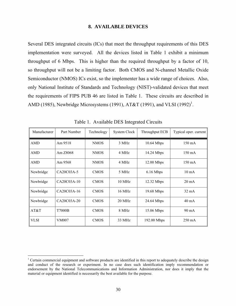
Several DES integrated circuits (ICs) that meet the throughput requirements of this DES
implementation were surveyed. All the devices listed in Table 1 exhibit a minimum
throughput of 6 Mbps. This is higher than the required throughput by a factor of 10,
so throughput will not be a limiting factor. Both CMOS and N-channel Metallic Oxide
Semiconductor (NMOS) ICs exist, so the implementer has a wide range of choices. Also,
only National Institute of Standards and Technology (NIST)-validated devices that meet
the requirements of FIPS PUB 46 are listed in Table 1. These circuits are described in
AMD (1985), Newbridge Microsystems (1991), AT&T (1991), and VLSI (1992)1.
Table 1. Available DES Integrated Circuits
Manufacturer Part Number Technology System Clock Throughput ECB Typical oper. current
AMD Am 9518 NMOS 3 MHz 10.64 Mbps 150 mA
AMD Am Z8068 NMOS 4 MHz 14.24 Mbps 150 mA
AMD Am 9568 NMOS 4 MHz 12.00 Mbps 150 mA
Newbridge CA20C03A-5 CMOS 5 MHz 6.16 Mbps 10 mA
Newbridge CA20C03A-10 CMOS 10 MHz 12.32 Mbps 20 mA
Newbridge CA20C03A-16 CMOS 16 MHz 19.68 Mbps 32 mA
Newbridge CA20C03A-20 CMOS 20 MHz 24.64 Mbps 40 mA
AT&T T7000B CMOS 8 MHz 15.06 Mbps 90 mA
VLSI VM007 CMOS 33 MHz 192.00 Mbps 250 mA
1 Certain commercial equipment and software products are identified in this report to adequately describe the design and conduct of the research or experiment. In no case does such identification imply recommendation or endorsement by the National Telecommunications and Information Administration, nor does it imply that the material or equipment identified is necessarily the best available for the purpose.
31
9. CONCLUSIONS
The 24-bit DES encryption method described in this report meets the requirements for an
LP mechanism. A single-bit error or change in a 24-bit cipher text word produces error
extension throughout the corresponding 24-bit plain-text word upon decryption. This
property, in conjunction with the use of a seed word containing time and frequency
information, allows the receiver to reject over-the-air manipulation of valid words, or
rebroadcast of cipher text words after a PI has expired. Analysis of required decryption
speed indicates that software implementation of this technique may not be feasible.
However, NIST-validated hardware devices that implement the DES algorithm are
available off-the-shelf with the required processing speeds. Therefore, it should be
possible to implement DES-based LP using currently available ICs.
10. ACKNOWLEDGEMENTS
The authors would like to thank Miles Smid of the National Institute of Standards and
Technology for providing guidance in the development of the DES-based scheme,
Dr. Eric Johnson of New Mexico State University for his significant technical leadership
in developing the linking protection concept, and John Harman of the Institute for
Telecommunication Sciences for producing the graphics presented in this report.
32
11. REFERENCES
AMD (Advanced Micro Devices) (1985), Data Ciphering Processors Am 9518, Am 9568,
and AmZ 8068 Data Sheets, Sunnyvale, CA.
AT&T (1991), T7000 Digital Encryption Processor Data Sheet, Berkeley Heights, NJ.
Johnson, E.E. (1991a), Linking Protection Requirements, New Mexico State University,
Las Cruces, NM.
Johnson, E.E. (1991b), Analysis of DES in 3 x 12 Mode For Link Protection, New
Mexico State University, Las Cruces, NM.
NCS (National Communications System) (1990), Federal Standard (FS) 1045 -
Telecommunications: HF Radio Automatic Link Establishment (Office of
Technology and Standards).
NCS (National Communications System) (1993), Federal Standard (FS) 1049 -
Telecommunications: HF Radio Automatic Operation in Stressed Environments,
Section 1: Linking Protection (Office of Technology and Standards).
Newbridge Microsystems, (1991), CA20C03A DES Encryption Processor Data Sheet,
Kanata, Ontario, Canada.
NIST (1980), Federal Information Processing Standard Publication (FIPS PUB) 81, DES
Modes of Operation.
NIST (1988), Federal Information Processing Standard Publication (FIPS PUB) 46-1,
Data Encryption Standard.
33
Redding, C., and Johnson, E.B. (1991), Linking Protection for HF Radio Automatic Link
Establishment, Proceedings of IEEE Military Communications Conference