LVS WIZARD GUIDE Linksys Voice System Installation, Configuration, and Maintenance Using the LVS Wizard SPA9000 IP Telephony System SPA400 PSTN VoIP Gateway with Integrated Voice Mail Server SPA9x2 IP Phones
Transcript
LVS WIZARD GUIDE
Linksys Voice SystemInstallation, Configuration, and Maintenance Using the LVS Wizard
SPA9000 IP Telephony SystemSPA400 PSTN VoIP Gateway with Integrated Voice Mail ServerSPA9x2 IP Phones
Contents
Linksys Voice System Wizard Guide i
About This Guide 1 5
Document Audience 5
Related Documents 5
Finding Information in PDF Files 6
Finding Text in a PDF 6
Finding Text in Multiple PDF Files 6
Online Resources 7
Copyright and Trademarks 7
Document Style Conventions 7
Getting Started 2 9
LVS Solution Overview 9
Introducing LVS Equipment 10
Getting to Know Your SPA9000 11
Getting to Know Your SPA400 12
Getting to Know Your SPA9xx Phones and Accessories 13
Getting to Know Your WRV200 Router 15
Getting to Know the SLM224P Switch 17
Installation and Configuration Process Overview 13 9
Preparation 24 0
Site Survey 20
System Design Considerations 20
Bandwidth Requirements and Call Capacity 20
Wide Area Network (WAN) Quality of Service 21
Network Setup Review 21
NAT Mapping 22
Contents
Linksys Voice System Wizard Guide ii
Quality of Service 22
Local Area Network Design 22
Deployment Scenarios 23
ITSP Service without Local PSTN Access or Voice Mail 23
LVS with ITSP Service, PSTN Access and Local Voice Mail Service 24
ITSP Service, PSTN and ISDN Access and Local Voice Mail Service 25
Services and Equipment 26
Basic Services and Equipment 26
Linksys Equipment and Services 26
Downloading Firmware 27
Connecting and Configuring Your System 25 9
Connecting and Configuring the Switch 29
Connecting the Switch to the Router 29
Configuring the Switch 30
Introduction to the Wizard 32
Wizard Capabilities 32
Extracting the Wizard 32
LVS Wizard User Guide 32
Connecting and Configuring the LVS Equipment (New Installation) 32
Configuring Steering Digits and Outbound Call Routes 53
Configuring the SPA400 Voice Mail Server for the SPA9000 (Optional) 54
Configuring the Internal Phone Extensions 55
Configuring Inbound Call Routing 56
Configuring Hunt Groups (Optional) 57
Localizing the SPA9000 60
Downloading Custom Auto Attendant Prompts (Optional) 62
Configuring Client Stations 66
Localizing the SPA400 Voice Mail Prompts (Optional) 73
Testing Your LVS System 76 6
Maintaining Your LVS 77 7
Using the Main Menu 78
Upgrading Firmware 80
Configuring Mediatrix Services 83
Backing Up and Restoring Device Configurations 84
Save Configuration to File 85
Save Configuration to Device 86
Expert User 90
End User License Agreement Registry Entry 90
Wizard Directories 90
Advanced Features Menu 91
NAT Settings 92
Client Extensions 97
Hunt Groups 98
Contents
Linksys Voice System Wizard Guide iv
Auto Attendant 100
Localizing the Language Dictionaries for the Phone Display 114
Admin Password 117
SPA932 Attendant Console 117
Adding a Phone to an Existing Configuration 120
Replacing a Phone [Experts Only] 122
Removing a Forgotten Password [Expert Only] 126
Installation Workbook 12A 7
Additional Equipment 138
Additional Installation and Configuration Notes 139
Contacts 14B 0
North American Contacts 140
Global Contacts 140
About This Guide Document Audience
Linksys Voice System Wizard Guide 5
About This Guide This guide helps you to prepare your site and to complete the basic installation and configuration of the Linksys Voice System (LVS) by using the Configuration Wizard This guide describes the LVS solution and its components It also presents step-by-step instructions to help you to install and configure the system, to select the features that the business needs, to verify the installation, and to resolve any problems that occur
• “Document Audience” on page 5
• “Related Documents” on page 5
• “Online Resources” on page 7
• “Copyright and Trademarks” on page 7
• “Document Style Conventions” on page 7
Document AudienceThis document is written for Linksys Voice System (LVS) administrators that need to:
Configure new LVS installations •
Configure existing LVS installations •
Backup and restore LVS configurations •
Related DocumentsLinksys strongly recommends the use of the LVS Wizard and this Installation and Configuration Guide when installing, configuring and maintaining your LVS systems Additionally, this section provides additional documentation references for administering the LVS system and its components
These documents and more are available at Linksys com and the Linksys Partner Connection (LPC) site
NOTE: EMEA customers can go to www linksys-itsp com and www linksys-voip eu
Document Title Description Intended AudienceLinksys Voice System Installation and Configuration Using the Administration Web Server
Manual installation of LVS, by •using the devices’ built-in Web User Interface, instead of the LVS Wizard
End Users, VARs, and Service Providers
Linksys Voice System Administration Guide
Administration and •configuration of system features using the SPA9000 and SPA400Deployment options for ITSP, •PSTN, and ISDN servicesSPA9000, SPA400, SPA900 series •phones
VARs and Service Providers
Linksys Phone Administration Guide Configuration and •management of SPA9x2 series IP phonesDeployment options with or •without the SPA9000 IP PBXSPA9x2 series IP phones •
Linksys SPA9x2 Phone User Guide Phone setup •Phone features •SPA9x2 series IP phones •
VARS and phone end-users
Linksys Analog Telephone Adapter Administration Guide
Administration and use of •Linksys ATAsPAP2T, SPA2102, SPA3102, •SPA8000, AG310, RTP300, WRP400, and WRTP54G
VARS, system administrators, and Service Providers
User Guide for chosen switch
User Guide for chosen router
Finding Information in PDF FilesThe PDF Find/Search tool lets you find information quickly and easily online You can:
Search an individual PDF •
Search multiple PDFs at once (for example, all PDFs in a specific folder or disk drive) •
Perform advanced searches •
Finding Text in a PDFEnter your search terms in the 1 Find box on the toolbar
NOTE: By default, the Find box is available at the right end of the Acrobat toolbar If the Find tool does not appear, choose Edit > Find
Optionally, click the arrow next to the 2 Find text box to refine your search by choosing special options such as Whole words only
Press 3 Enter Acrobat displays the first instance of the search term Press Enter again to continue to more instances of the term
Finding Text in Multiple PDF FilesThe Search window lets you search for terms in multiple PDF files that are stored on your PC or local network The PDF files do not need to be open
Start Acrobat Professional or Adobe Reader 1
Choose 2 Edit > Search Alternatively, click the arrow next to the Find box and then choose Open Full Acrobat Search
In the 3 Search window, complete the following steps:
Enter the text that you want to find a
Choose b All PDF Documents in
From the drop-down box, choose c Browse for Location
Choose a directory on your computer or local network, and click d OK
If you want to specify additional search criteria, click e Use Advanced Search Options, and choose the options you want
About This Guide Online Resources
Linksys Voice System Wizard Guide 7
Click f Search
When the Results appear, click the plus sign (4 +) to open a folder, and then click any link to open the file where the search terms appear
NOTE: For more information about the Find and Search functions, see the Adobe Acrobat online help
Online ResourcesWebsite addresses in this document are listed without http:// in front of the address because most current web browsers do not require it If you use an older web browser, you may have to add http:// in front of the web address
Resource Website
Linksys www linksys com
Linksys International www linksys com/international
Parameters: • Angle brackets and italic type indicate parameters that you need to replace with the appropriate data
Example: Type 800@<IP address of SPA400>:5090
In this example, you would type the characters 800@, followed by the IP address of your SPA400, followed by a colon and the number 5090
Linksys Voice System Wizard Guide 9
1 Getting StartedLVS Solution Overview
Getting StartedBefore you start installing and configuring your system, you need to become familiar with the features of the Linksys Voice System and the equipment and services that are required to meet the needs of the business
This chapter is essential reading before you begin installing the equipment or configuring the system Refer to the following topics:
• “LVS Solution Overview ” on page 9
• “Introducing LVS Equipment” on page 10
LVS Solution Overview The Linksys Voice System (LVS) is an affordable, feature-rich, multi-line voice over IP (VoIP) telephone system that provides sophisticated communication services to small business users The LVS uses standard TCP/IP protocols (although UDP is also supported) and can provide global connectivity through any Internet Telephony Service Provider (ITSP) that supports Session Initiation Protocol (SIP)
The IP PBX system (SPA9000) provides powerful business-class services on a small business budget The system capitalizes on VoIP service savings for long distance outbound and toll-free inbound calling Features include Auto Attendant, shared line appearances, configurable call routing, multiple DID numbers per VoIP line, call hunting (sequential, round robin, random), call park/unpark, call transfer, call forward, group paging, call pick-up, music on hold, “find me” service, Do Not Disturb, call hold, call waiting, and more Administrative tasks can be performed using an Interactive Voice Response system or a built-in Web Server
With the optional SPA400 PSTN Gateway, the LVS provides full inter-connectivity with the Public Switched Telephone Network (PSTN) Thus, a small business can maintain its legacy PSTN lines and existing telephone numbers The SPA400 also provides an integrated local voice mail server for up to 32 individual mail boxes
Additional third party products such as Mediatrix® 4400 ISDN VoIP Gateways and Plantronics® and GNNetcom®/Jabra® headsets provide enhanced connectivity for supporting additional business deployment scenarios Please contact your linksys distributor or sales representative for further information on Linksys LVS third party products
Getting StartedIntroducing LVS Equipment
Linksys Voice System Wizard Guide 10
LVS Solution Overview
As illustrated, the complete LVS solution typically includes the SPA9000 IP PBX system, the SPA400 PSTN gateway with voice mail, and several SPA9xx series IP phones The system has VoIP telephone service through an Internet Telephony Service Provider (ITSP) but also supports legacy telephone lines (PSTN lines) through the SPA400
The following devices can be connected to an LVS system:
Analog phones, fax machines: • Up to two analog phones or fax machines can be connected to the VoIP network through the SPA9000
Telephone service through PSTN, ITSP, and ISDN: •
ITSP VoIP Service: – The SPA9000 can be configured to subscribe to an Internet Telephone Service Provider for VoIP service Up to four different ITSP accounts can be configured
PSTN Analog Phone Access: – The SPA400 can accommodate up to four PSTN lines, to support legacy phone numbers Typically, one SPA400 is reserved for voice mail service If your system has ITSP service, you can add up to two SPA400 devices with a total of 8 PSTN lines If your system does not have ITSP service, you can add a third SPA400 device with 4 additional PSTN lines, for a total of 12 PSTN lines
ISDN services: – The LVS can be deployed with a Mediatrix® 4400 ISDN BRI Digital gateway for ISDN access
Introducing LVS EquipmentThis chapter describes the features of the LVS equipment, including the SPA9000, the SPA400, and the various models of SPA9xx phones
• “Getting to Know Your SPA9000 ” on page 11
• “Getting to Know Your SPA400 ” on page 12
• “Getting to Know Your SPA9xx Phones and Accessories” on page 13
SPA9xx IP Phones
SLM224P Switch SPA9000 IP PBX
WRV200 Router
Internet
Integrated Access Device
Analog Phone Lines
SPA400 for Voice Mail
SPA400 for PSTN Access
Analog Phonesor Fax Machines
Getting StartedIntroducing LVS Equipment
Linksys Voice System Wizard Guide 11
• “Getting to Know Your WRV200 Router” on page 15
• “Getting to Know the SLM224P Switch” on page 17
Getting to Know Your SPA9000 The SPA9000 is an IP PBX system with high-end features comparable to traditional large business voice services This section describes the LEDs on the front panel and the ports on the back panel of the device
SPA9000 Front Panel
LED Description/NotesPower Green: The device is receiving power and is connected to the Internet •
Flashing Green: The device is receiving power but is not connected to the •Internet
Unlit: The device is not receiving power •
Internet Green: The device is connected to the Internet •
Flashing Green: The device is experiencing network activity •
Unlit: The device is not connected to the Internet •
Phone 1, Phone 2 Green: The phone is on hook and is registered with an active Internet •phone service account
Unlit: The phone is on hook but is not registered with an active Internet •phone service account
Flashing Green: The phone is off hook •
Getting StartedIntroducing LVS Equipment
Linksys Voice System Wizard Guide 12
SPA9000 Back Panel
Port Description/NotesPhone 1, Phone 2 Use these ports to connect analog phones or fax machines to your IP phone
account
Ethernet Use this port to connect a computer for administration of the SPA9000
Internet Use this port to connect the SPA9000 to the Local Area Network (LAN) The cable may be connected to a switch, router or Integrated Access Device
Power Use this port to connect to the external Power adapter (PA100)
Getting to Know Your SPA400 The SPA400 provides the SPA9000 access to the PSTN by connecting the FXO ports to analog lines The SPA400 sets up and tears down calls between the PSTN and IP phones, offering seamless telephone service with Linksys VoIP equipment
The SPA400 also has a built-in voice mail server
This section describes the LEDs on the front panel and the ports on the back panel of the device
SPA400 Front Panel
LED Description/NotesPower Steady green: The SPA400 is receiving power and is connected to the •
Internet
Flashing: The SPA400 is not connected to the Internet, booting, or •upgrading firmware
Status Steady green: The SPA9000 is registered to the SPA400 •
Flashing: The SPA9000 is not registered to the SPA400 •
Ethernet Steady green: The SPA400 has an active connection through the Ethernet •port
Flashing: Network activity is occurring over the Ethernet port •
Getting StartedIntroducing LVS Equipment
Linksys Voice System Wizard Guide 13
LED Description/NotesLine 1, 2, 3, 4 Steady green: The line is active •
Flashing: The line is ringing •
Off: The line is idle •
USB Steady green: The USB voice mail module is registered •
Off: No module is detected •
SPA400 Back Panel
Port Description/NotesUSB Use this port for the USB voice mail module, which contains the voice
mail prompts and provides the storage location for saving voice mailbox messages
Ethernet Use this port to connect to the Local Area Network (LAN) for communications with SPA9000
Line 1, 2, 3, 4 These FXO ports are used to connect to an analog phone lines
Reset This button is used to reset the device
Power Use this port to connect to the external Power adapter (PA100)
Getting to Know Your SPA9xx Phones and AccessoriesLinksys provides are variety of phone models to suit the needs of small businesses The following table provides a comparison of the various SPA9xx phones
Product Name RJ-45 Voice Lines Additional Features/Notes
SPA922* 2 1 One-line IP phone with Power over Ethernet (PoE) support
SPA942* 2 4 Four-line IP phone with Power over Ethernet (PoE) support
Getting StartedIntroducing LVS Equipment
Linksys Voice System Wizard Guide 14
Product Name RJ-45 Voice Lines Additional Features/Notes
SPA962* 2 6 Six-line IP Phone with high-resolution color display and Power over Ethernet (PoE) support
SPA932 — — Attendant console (sidecar) for SPA962 with 32 buttons and LEDs for monitoring and call transfer
POES5 1 N/A Provides an 802 3af PoE port for connection back to a PoE switch for SPA9000, SPA400 and SPA9x1 phones
WBP54G 1 N/A Converts your IP phone into a wireless device, so it can connect to your wireless network without an Ethernet cable
*NOTE: PoE units (SPA922, SPA942, and SPA962) do not come with an external power adapter The PA100 power supply must be ordered separately if you are not using a PoE switch
Getting StartedIntroducing LVS Equipment
Linksys Voice System Wizard Guide 15
Getting to Know Your WRV200 RouterWRV200 is a VPN router with a Wireless-G access point for small offices and home offices It is strongly recommended for use with the Linksys Voice System
WRV200 Front Panel
LED/Port DescriptionPower Green: The router is receiving power •
Flashing Green: The router is running a diagnostic test •
DMZ Green: The router has an available DMZ port •
Flashing Green: The router is sending or receiving data over the DMZ port •
Internet Green: The router is connected to a Broad Band Access device at the •indicated speed (10, 100, 1000)
Flashing Green: The router is transmitting or receiving data over the •Internet port
Wireless Green: The router has a successful wireless connection •
Flashing Green: The Router is actively sending or receiving data over the •wireless network
1-4 (Ethernet) These four LEDs correspond to the router’s four Ethernet ports
Green: The Router is connected to a device through the corresponding •port (1, 2, 3, or 4)
Flashing Green: The Router is actively sending or receiving data over the •corresponding port
Getting StartedIntroducing LVS Equipment
Linksys Voice System Wizard Guide 16
WRV200 Back Panel
LED/Port DescriptionPower The port is used to connect the router to AC power, using the provided power
cable
Reset The Reset button has two functions: •
If the Router is having problems connecting to the Internet, press the •Reset button for just a second with a paper clip or a pencil tip This is similar to pressing the Reset button on your PC to reboot it
If you are experiencing extreme problems with the router and have tried •all other troubleshooting measures, press and hold in the Reset button for 10 seconds This action restores the factory defaults and clears all of the Router’s settings, such as port forwarding or a new password
Internet Use this port to connect the router to a Broad Band Access device
1-4 (Ethernet) Use these ports to connect the router to network devices, such as PCs, print servers, or additional switches
Getting StartedIntroducing LVS Equipment
Linksys Voice System Wizard Guide 17
Getting to Know the SLM224P SwitchThe SLM224P switch has 24 10/100 Copper ports with two shared Gigabit copper or optical (SFP) uplink interfaces for connecting the switch to the core network
NOTE: In this guide, the SLM224P switch is used in all examples However, various Linksys switches can be used with the LVS Linksys recommends use of SLMxxxP, SRWxxxP and SRWxxxMP switch product families with the LVS
SLM224P Front Panel
LED/Port DescriptionSystem Green: Power is being supplied to the switch •
Solid Amber: The switch is performing the Power-On Self Test (POST) •
Link/Act (1-24) Green: The switch has a functional 10/100 Mbps network link through the •corresponding port with an attached device
Flashing: The switch is actively sending or receiving data over the •corresponding port
PoE (1-6, 13-18) Flashing Amber: Power is being supplied to an attached powered device •(PD) on the corresponding port (1 through 6, 13 through 18)
100M (7-12, 19-24) Amber: The switch has a functional 100 Mbps connection on the •corresponding port (7 through 12, 19 through 24) with an attached device
Link/Act (G1-G2) Green: Lights up to indicate a functional 10/100/1000 Mbps network link •through the corresponding port (G1 through G2) with an attached device
Flashing Green: The switch is actively sending or receiving data over the •corresponding port
Gigabit (G1-G2) Amber: The switch has a functional 1000 Mbps connection on the •corresponding port with an attached device
Reset To reboot the switch, press and hold the Reset button for approximately •five seconds
To reset the Switch settings to the factory defaults, press and hold the •Reset Button for approximately ten seconds
Ethernet (1-24) The Switch is equipped with 24 auto-sensing, Ethernet network ports, which use RJ-45 connectors The Fast Ethernet ports support network speeds of 10 Mbps, 100 Mbps, or 1000 Mbps They can operate in half- and full-duplex modes Auto-sensing technology enables each port to automatically detect the speed of the device connected to it (10 Mbps, 100 Mbps, or 1000 Mbps), and adjust its speed and duplex accordingly
G1-G2 The switch is equipped with 2 auto-sensing 10 Mbps, 100 Mbps, or 1000 Mbps Gigabit Ethernet network ports, which use RJ-45 connectors They can operate in half- and full-duplex modes
mini-GBIC (1-2) The mini-GBIC (gigabit interface converter) port is a connection point for a mini-GBIC expansion module, so the switch can be uplinked via fiber to another switch
Getting StartedIntroducing LVS Equipment
Linksys Voice System Wizard Guide 18
SLM224P Back Panel
The back panel has one port, the Power port, which is used to connect the power cord
Linksys Voice System Wizard Guide 19
2 Installation and Configuration Process Overview
Installation and Configuration Process OverviewThis chapter provides an overview of the installation and configuration process
PreparationA. In Chapter 3, “Preparation”, you learn about the equipment and service requirements, bandwidth requirements, call capacity, and related topics , to ensure that the system is well designed to meet the needs of the customer This chapter also describes basic procedures such as downloading firmware, which should be completed before you begin installing the equipment
Connecting and Configuring the LVS Using the WizardB. In this phase, you will physically connect the LVS equipment to the LAN, configure the voice features, call routing, localization and business features using the LVS Wizard Chapter 4, “Connecting and Configuring Your System” explains step-by-step use of the Wizard for the purpose of Installing and Configuring your system
Testing the LVS Installation and ConfigurationC. After the system is installed and configured using the LVS Wizard, it is recommended that you perform some basic tests to ensure that the LVS system is properly installed and configured Chapter 5, “Testing Your LVS System” provides basic steps for verifying your LVS system is properly installed and is operational
Maintaining the LVS Using the WizardD. After the system is installed, configured and operational, it is possible that you require to update the system (e g to add a new extension because there is a new employee on the business, or to add a new SPA400 because of additional PSTN traffic) Chapter 6, “Maintaining Your LVS” explains all individual menu options for performing basic and advanced configuration tasks
Linksys Voice System Wizard Guide 20
3 PreparationSite Survey
PreparationTo ensure that the installation process goes smoothly, verify that you have the services, equipment, and information described in the following sections This chapter is essential reading before you begin installing the equipment or configuring the system Refer to the following topics:
• “Site Survey” on page 20
• “System Design Considerations” on page 20
• “Network Setup Review” on page 21
• “Deployment Scenarios” on page 23
• “Services and Equipment” on page 26
• “Downloading Firmware” on page 27
Site SurveyThe site surveys consists of gathering relevant information about the customer, the existing infrastructure, the network, the telephone equipment, and the available services This survey helps you to prepare for the installation of the LVS equipment (for example, ordering the LVS components from the distribution channel) and to anticipate the design considerations The site survey can be conducted on the customer premises or remotely over the phone and e-mail
Various site survey templates can be used Appendix A, “Installation Workbook”, contains a site survey template example, used to fill the customer information
System Design ConsiderationsWhen installing and configuring the LVS, it is necessary to analyze and meet some design considerations to ensure the best quality and user experience The design considerations cover available bandwidth and quality of service
Bandwidth Requirements and Call CapacityThe available connection bandwidth determines the maximum number of simultaneous calls that the system can support with the appropriate audio quality Before installing and configuring the LVS components, use this information to determine the maximum number of simultaneous VoIP connections that the system can support For asymmetric connections, such as ADSL, the maximum number of calls is determined by the upstream bandwidth In general it is a good practice to use no more than 75% of the total available bandwidth for calls This provides space for data traffic and helps ensure good voice quality
The following table provides the approximate bandwidth budget for different codecs
Codec Approximate bandwidth budget for each side of conversation
NOTE: Some ITSP SIP trunk services limit the maximum number of simultaneous calls Please check with your Service Provider to understand the maximum number of simultaneous calls each SIP trunk supports
For more information about bandwidth calculation, refer to the following web sites:
http://www erlang com/calculator/lipb/
http://www packetizer com/voip/diagnostics/bandcalc html
Wide Area Network (WAN) Quality of ServiceYou can choose from several types of broadband access technologies to provide symmetric or asymmetric connectivity to a small business These technologies vary on the available bandwidth and on the quality of service It is generally recommended that you use broadband access with a Service Level Agreement that provides quality of service If there is not a Service Level Agreement with regard to the broadband connection quality of service, the downstream audio quality may be affected negatively under heavy load conditions (bandwidth utilization beyond 80%) To eliminate or minimize this effect, Linksys recommends one of the following actions:
For broadband connections with a bandwidth lower than 2 Mbps, perform the call capacity •calculations by assuming a bandwidth value of 50% of the existing broadband bandwidth For example, in the case of a 2 Mbps uplink broadband connection, assume 1 Mbps Limit the uplink bandwidth in the Integrated Access Device to this value This setting helps to maintain the utilization levels below 60%, thus reducing jitter and packet loss
Use an additional broadband connection for voice services only A separate connection is required •when the broadband connection services do not offer quality of service and when it is not possible to apply the above mentioned utilization mechanism
Network Setup ReviewThe Local Area Network (LAN) is the communication platform used by the LVS for allowing communications among the telephone users and between the telephone users and the external VoIP, PSTN or/and ISDN network services This LAN is composed of the data wiring (UTP cabling), networking equipment (switches and routers/access device) and the telecommunication (PSTN or ISDN) lines
The Local Area Network (LAN) may be already installed or it can be installed and configured at the time of installing the LVS system Below are the general recommendations for Local Area Networks running LVS communications:
Infrastructure, Cabling and PSTN/ISDN Lines:
AC outlets: • Ensure there is an AC outlet available for every LAN and LVS component that requires AC power If you are using a Power over Ethernet switch, SPA9x2 phones do not require an AC outlet as they are powered by the switch
Ethernet cabling: • Ensure there is a Ethernet cabling system and outlets setup for every LVS component to install It is recommended that Ethernet cables are UTP CAT 5e or better
PSTN and ISDN lines: • Ensure that the lines are operative and that any features, such as caller identification, operate properly before starting the installation Ensure that the cables are available in the location where you are installing the LVS components
UPS: • If you are using an Uninterrupted Power Supply (UPS) mechanism, ensure that the LVS design is covered by the UPS by securing the router and switch AC connections, and the LVS components, by using the Power over Ethernet adapter (POES5) for the non-POE products (SPA9000, SPA400, SPA9x1 phones) Also ensure that devices such as the WAN modem, CSU/DSU, or DDS modem are connected to the UPS
NAT MappingNetwork Address Translation (NAT) is a function that allows multiple devices to share the same public, routable, IP address to establish connections over the Internet NAT is present in many broadband access devices to translate public and private IP addresses To enable VoIP to co-exist with NAT, some form of NAT traversal is required
Some ITSPs provide NAT traversal, but some do not If your ITSP does not provide NAT traversal, you have several options
NAT mapping with SIP-ALG router •
Use a router such as the WRV200, which has a SIP ALG (Application Layer Gateway) With a SIP ALG in the router, you have more choices in selecting an ITSP
ITSP that supports NAT mapping through a Session Border Controller •
With NAT mapping provided by the ITSP, you have more choices in selecting a router
NAT mapping with the SPA9000 EXT IP setting •
Configuring NAT mapping in the SPA9000 is recommended only if the ITSP network does not provide a Session Border Controller functionality In this case, and if the external (public) IP address is static, then it is recommended to perform a static (permanent) mapping on SPA9000 Instructions are available in the LVS Administration Guide
Configuring NAT Mapping with STUN •
Configuring NAT mapping in the SPA9000 is recommended only if the ITSP network does not provide a Session Border Controller functionality In this case, and if the external (Public) IP address is assigned dynamically by the network (and the router uses asymmetric NAT mechanism), it is possible to use STUN as a mechanism to discover the NAT mapping in SPA9000 This is considered a practice of last resort and should be used only if the other methods are unavailable For more information, see the LVS Administration Guide
Quality of ServiceLinksys recommends using the LVS with QoS-capable networking equipment that can prioritize the VoIP application traffic QoS features are available on many Linksys data networking switches (such as the SLM224P) and routers (such as WRV200) A QoS-enabled router prioritizes the packets going upstream to the Internet Service Provider QoS can be enforced using either DSCP IP TOS (recommended for its simplified setup) or 802 1 Q/p VLAN ID and priority setting
Instructions for the SLM224P are provided in this guide
Local Area Network DesignUse the following guidelines to manage the LAN setup for the LVS
Ensure that all LVS components are located in the same local area network subnet •
Although all LVS components support static IP addressing, we recommend the use of a DHCP •server, as a means to easily add IP telephones to the system Ensure that the DHCP server can assign up to enough IP addresses to serve the LVS phones and the existing networked components such as PCs, servers, and so on
If using DHCP, use a long lease time LVS components may reboot on the event of an IP address •change because of lease time expiration
Use stable DNS server addresses for URL name resolution Your Internet Service Provider can •provide the primary and secondary DNS server IP addresses
PreparationDeployment Scenarios
Linksys Voice System Wizard Guide 23
Deployment ScenariosTo ensure that the system meets the customer’s needs, consider the requirements for PSTN access, VoIP service, voice mail, and legacy equipment such as analog phones and fax machines Also consider the number of IP phones that are required to handle the expected call volume
ITSP Service without Local PSTN Access or Voice MailIn this scenario, the customer requires a robust phone system but is not using VoIP services The LVS is deployed with a SPA9000 IP PBX, one SPA400 for PSTN access with four FXO ports, and another SPA400 for local voice mail service Four phones are connected at this time, but the LVS can be expanded to include up to 16 SPA9xx IP phones Optionally, analog phones or fax machines (not illustrated) can be connected to the two phone ports on the SPA9000
SPA9xx IP Phones
SLM224P SwitchSPA9000 IP PBX
WRV200 Router
Internet
Integrated Access Device
PreparationDeployment Scenarios
Linksys Voice System Wizard Guide 24
LVS with ITSP Service, PSTN Access and Local Voice Mail ServiceIn this scenario, a customer wants to use ITSP service for reduced long distance fees but needs to support legacy local telephone numbers (for example, to receive calls over the original-legacy telephone number, or to route local telephone calls) This customer also prefers local voice mail service The solution is to deploy LVS with the SPA9000 IP PBX, VoIP service, one SPA400 unit for voice mail service, and one or two additional SPA400 units for PSTN access (four FXO ports per unit), and up to 16 SPA9xx phones Optionally, analog phones and fax machines can be added
SPA9xx IP Phones
SLM224P Switch SPA9000 IP PBX
WRV200 Router
Internet
Integrated Access Device
Analog Phone Lines
SPA400 for Voice Mail
SPA400 for PSTN Access
PreparationSystem Design Considerations
Linksys Voice System Wizard Guide 25
ITSP Service, PSTN and ISDN Access and Local Voice Mail ServiceIn this scenario, the customer takes full advantage of the LVS solution, with the SPA9000 IP PBX, VoIP service, one SPA400 unit for voice mail service, and one additional SPA400 unit for PSTN access (four FXO ports per unit), one ISDN Gateway for ISDN BRI access (up to four BRI ports per unit), and up to 16 SPA9xx IP phones Optionally, analog phones and fax machines can be added
SPA9xx IP Phones
SLM224P Switch SPA9000 IP PBX
WRV200 Router
Internet
IntegratedAccess Device
Analog Phone Lines
SPA400 for Voice Mail
SPA400 for PSTN Access
Mediatrix® 4402 BRI Gateway
ISDNPhone Lines
PreparationServices and Equipment
Linksys Voice System Wizard Guide 26
Services and EquipmentTo install and configure LVS, you need the following services and equipment
Basic Services and EquipmentThe following basic services and equipment are required:
An Integrated access device or modem for broadband access to the Internet; business grade •account recommended
Internet Telephony Service Provider (ITSP) for Voice Over IP telephone service •
You must have at least the following information about your account:
SIP Proxy (IP address or name) –
Account Information and Password –
Computer with Microsoft Windows XP or Windows Vista (for system configuration) •
Analog phone for administrative use with the SPA9000 Interactive Voice Response (IVR) system •
Uninterruptible Power Source (UPS), recommended for devices such as the Integrated Access •Device, network switch, router, and PoE switch to ensure continuous operation during a power failure
Optional Mediatrix® gateway for ISDN connectivity •
Linksys Equipment and ServicesThe following LVS equipment is recommended:
SPA9000 IP PBX •
One SPA9000 unit is required for IP PBX features Only one SPA9000 is supported
SPA400 PSTN Gateway and Voice Mail Server •
It is recommended that you install one SPA400 unit exclusively for voice mail service and one or more additional SPA400 units for PSTN access Each unit has four FXO ports and occupies one line interface on the SPA9000 With ITSP service taking one line interface on the SPA9000, up to three SPA400 units can be installed With no ITSP service, up to four SPA400 units can be installed
SPA9xx series IP phones •
The SPA9x1 series phones require access to power outlets The SPA9x2 series phones can receive power from a Power over Ethernet (PoE) switch and are not supplied with power supplies If you are not using the recommended PoE switch, you need to purchase a suitable power supply or power injector for the SPA9x2 phones
Switch (example: SLM224P) •
Router (example: WRV200) •
Optional POES5 Power over Ethernet adapters, for providing POE-derived power to non-POE LVS •devices such as SPA9000, SPA400 and SPA9x1, in case UPS is available
Optional WBP54G Wireless-G adapter, for providing Wireless client functionality to IP Phones, if •required to connect a phone to the LAN using Wireless technology
PreparationDownloading Firmware
Linksys Voice System Wizard Guide 27
Downloading FirmwareBefore installing and configuring your system, download the latest LVS Wizard and firmware for your SPA9000, SPA400 (if present), and SPA9xx phones
This guide supports the following firmware releases The installed firmware must be at least the indicated in the table below
Product Firmware Version SPA9000 5 2 5
SPA400 1 0 1 9
SPA922/942/962 5 2 8
SPA901 5 1 5
SPA921/SPA941 5 1 8
NOTE: This firmware is included as part of the LVS Wizard compressed archive file If you install newer firmware, follow the instructions below For ease of installation via the Wizard, extract the files to the same root directory of the Wizard
Start Internet Explorer, and enter the following URL: 1 http://www linksys com
From the menu at the top of the page, select 2 Support > Technical Support
Click 3 Choose a Product
NOTE: If you are visiting the site for the first time, you may be prompted to choose your location before continuing
On the 4 Select Product Category page, choose IP PBX from the Voice over IP (VoIP) drop-down list
On the 5 Choose The Device page, choose SPA9000
Under 6 Downloads, choose the Click Here link
Choose the version in the drop-down list 7
Under 8 Firmware, click the link for the latest version of the firmware
NOTE: If you are using Windows XP Service Pack 2 (SP2) and Internet Explorer, you may see the “Pop-up blocked” message in your browser information bar If you see this message, click the information bar and select Temporarily Allow Pop-ups Then click the link again
Click 9 Save in the File Download dialog box that appears
In the 10 Save As dialog box, choose a location for the file and then click Save
When the download is complete, if prompted, click 11 Close
NOTE: The name of the file depends on the firmware file of your device If the firmware file you download is in zip format, double-click the file and extract its contents to a single folder or to the desktop To extract the firmware file from the archive, use a utility such as WinZip, or use the built-in decompression features of Windows XP
Continue as needed for the other devices in your LVS:12
SPA400 –
Click a Choose A Product in the left navigation pane
On the b Choose A Product page, choose IP PBX from the Voice over IP (VoIP) drop-down list
Choose c SPA4000 on the Choose The Device page
On the SPA400 page, choose the d Click Here link under Downloads
Choose the version in the drop-down list e
Under f Firmware, click the link for the latest version of the firmware
Save the file g
SPA9xx IP Phones –
Click a Choose A Product in the left navigation pane
On the b Choose A Product page, choose VoIP Phones from the Voice over IP (VoIP) drop-down list
On the c Choose The Device page, scroll down to the end of the page Choose the correct model from the drop-down list for the SPA9xx phones
NOTE: There are separate drop-down lists for the SPA962 and the SPA932
On the SPA400 page, choose the d Click Here link under Downloads
Choose the version in the drop-down list e
Under f Firmware, click the link for the latest version of the firmware
Save the file g
NOTE: You will install the firmware after connecting the devices
Linksys Voice System Wizard Guide 29
4 Connecting and Configuring Your SystemConnecting and Configuring the Switch
Connecting and Configuring Your SystemThis chapter explains how to connect your equipment and upgrade the firmware Connect the equipment in the described order At the end of each section, you verify that the installation is progressing correctly
Connecting and Configuring the SwitchBefore installing any LVS equipment, you need to connect the SLM224P Ethernet switch to a network broadband router or Integrated Access Device (IAD) (If the site is not already equipped with another broadband router/IAD, Linksys recommends the use of the WRV200 broadband router to connect to the access device )
NOTE: In this guide, the Linksys SLM224P switch is used in all examples However, various Linksys switches can be used with LVS Linksys recommends use of SLMxxxP, SRWxxxP and SRWxxxMP switch product families with LVS For more information, visit www linksys com
• “Connecting the Switch to the Router” on page 29
• “Configuring the Switch” on page 30
Connecting the Switch to the Router
In this procedure, you connect the switch to the router and a power source
Connect an Ethernet network cable to one of the Ethernet ports on your router Then connect the 1 other end of the cable to an Ethernet port on the switch
Connect an administrative computer to an Ethernet port on the switch The PC needs to have an 2 IP address on the same network as the switch, which has a default IP address of 192 168 1 254
Connect the power cord to the power port, and then connect the power adapter to an electrical 3 outlet
The Power LED is solid amber during the Power-On Self Test (POST) Then the LED is solid green You are ready to configure the switch
Connecting and Configuring Your SystemConnecting and Configuring the Switch
Linksys Voice System Wizard Guide 30
Configuring the SwitchYou need to enable port fast to facilitate the broadcast communications between the SPA9000 and the phones You also need to configure the Quality of Service settings to help to prevent network delays affecting voice communications
Enable spanning tree and port fast •NOTE: If the switch does not provide a way to enable port fast, then you must disable spanning tree The preferred method is to enable spanning tree and port fast
Enable QoS with DSCP •
Enabling Port Fast on the SLM224P Switch
To avoid timing issues related to Spanning Tree Protocol (STP) and to allow multicasting to work correctly for LVS, enable port fast on the switch ports that will be connected to the SPA9000 and the SPA9xx IP phones
When Port Fast is enabled, Fast Link mode is active In Fast Link mode, the Port State is automatically placed in the forwarding state when the port link is up Fast Link optimizes the STP protocol convergence STP convergence can take 30-60 seconds in large networks
Choose the ports that you will use to connect the SPA9000 and the IP phones 1
Connect the administration computer to the switch 2
Start Internet Explorer, and enter the IP address of the switch 3
NOTE: The default IP address of the switch is 192 168 1 254 The default User ID is admin, with no password After you log on, the Home page appears
Click 4 Spanning Tree tab > STP Port Settings
From the 5 Port drop-down list, choose the port number for the SPA9000
Make sure that the 6 Enable STP check box is checked, to enable STP on the port
From the 7 Port Fast drop-down list, choose Enable
Click 8 Update
Repeat the previous steps, to enable Port Fast on each port where an IP phone or a SPA400 will be 9 connected
Click 10 Save Settings
Connecting and Configuring Your SystemConnecting and Configuring the Switch
Linksys Voice System Wizard Guide 31
Setting QoS on the SLM224P Switch
To avoid possible network related delays, configure QoS on the switch
Click 1 QoS tab > CoS Settings
From the 2 QoS Mode list, select Basic
Click 3 Save Settings
Click 4 QoS tab > Basic Mode
From the 5 Trust Mode list, select DSCP
Click 6 Save Settings
Connecting and Configuring Your SystemIntroduction to the Wizard
Linksys Voice System Wizard Guide 32
Introduction to the WizardThe Wizard steps you through the entire installation process, from connecting cables, powering on, configuring the Auto Attendant
Wizard CapabilitiesThe Wizard assists with advanced tasks, including:
Backing up and restoration of device configuration•
Changing device’s network settings•
Upgrading device’s firmware•
Configuring NAT settings•
Configuring SIP trunks in only a few clicks•
Extracting the WizardYou must unzip all of the files from the zip archive before starting the Wizard The Wizard will not properly function if you double-click the Wizard file within the compressed archive file
LVS Wizard User GuideClick User Guide to display this User Guide The User Guide must exist in the Wizard’s messages directory In the event that the file is not found, download the LVS Wizard User Guide from the SPA9000 download page at the Linksys com site Then open the Wizard folder, move the file to the messages sub-directory, and change its name to ug_english .pdf
Connecting and Configuring the LVS Equipment (New Installation)Refer to this section if you have a new installation and configuration to perform
This section assumes that:
You have some basic networking knowledge •
The LVS Equipment is not connected or powered on •
You are configuring an Internet telephony service provider (ITSP) account and a public •switched telephone network (PSTN) account
You have completed the Site Survey See • Appendix A, “Installation Workbook”
Connecting and Configuring Your SystemConnecting and Configuring the LVS Equipment (New Installation)
Linksys Voice System Wizard Guide 33
Required InformationBe prepared to provide the following information in response to the Wizard prompts:
NOTE: When choosing static IP addresses for your LVS equipment, it is recommended to set an IP address that is outside the address range assigned by the DHCP server For example, if the DHCP server assigns IP addresses in the range from 192 168 1 50 to 192 168 1 254, you should select a static IP address between 192 168 1 2 and 192 168 1 49
Connecting and Configuring Your SystemConnecting and Configuring the LVS Equipment (New Installation)
Linksys Voice System Wizard Guide 34
Phones
Name Primary Extension
Voice Mail (Yes or No)
MAC Address Ending
SPA9000 FXS 1
SPA9000 FXS 2
1
2
3
4
5
6
7
8
9
10
11
12
13
14
15
16
Connecting and Configuring Your SystemConnecting and Configuring the LVS Equipment (New Installation)
Linksys Voice System Wizard Guide 35
Call Routing Rule (choose one method):
Auto Attendant to answer all calls in _____ seconds •
Ring extension _____________ for _____ seconds •
Ring the Auto Attendant immediately •
Hunt Groups (Optional):
Group Name Group Extension Number Member Extension Numbers
Starting the WizardDouble-click the SetupWizard .exe file to start the LVS Wizard When the Welcome page appears, click Next to continue
End User License AgreementYou must click EULA, read the license agreement, and click Accept in order to use the Wizard for the first time The Wizard displays the SPA9000 Installation page once you have accepted the EULA
Connecting and Configuring Your SystemConnecting and Configuring the LVS Equipment (New Installation)
Linksys Voice System Wizard Guide 36
Installing the SPA9000
The Wizard guides you through the process of installing the SPA9000
Start the Wizard 1
To install and configure a new system, click the first option, 2 This is the first time . . .
Internet Integrated Access Device
Router
Analog Phone (IVR)
Admin. PC
Power
SLM224P Ethernet Switch
SPA9000IP PBX
Connecting and Configuring Your SystemConnecting and Configuring the LVS Equipment (New Installation)
Linksys Voice System Wizard Guide 37
NOTE:
Use the second option if you have previously configured this SPA9000, and the – C:\linksys\PBX<mac address>.act file exists
The Advanced Feature Menu is for experienced users only See – Chapter 6, “Maintaining Your LVS”
The Wizard will notify you if you select the first-time option but have previously configured –the SPA9000 Select Yes to cause the Wizard to extract and use the configuration from the C:\linksys\PBX<mac_address_SPA9000>.act file Select No to cause the Wizard to delete the C:\linksys\PBX<mac_address_SPA9000>.act file
Click 3 Next to continue to the Network Installation page
Connecting and Configuring Your SystemConnecting and Configuring the LVS Equipment (New Installation)
Linksys Voice System Wizard Guide 38
Follow the instructions on the 4 SPA9000 Network Installation page to connect the SPA9000
NOTE:
Do not connect anything to the SPA9000’s ETHERNET port Refer to the – LVS Administration Guide for more information about the ETHERNET port Use only the SPA9000’s INTERNET port
You will not hear sound from the analog phone when you take it off-hook Press **** (star/ –asterisk 4 times) to hear the integrated voice response (IVR) system
Click 5 Next to continue to the next page Continue with the next procedure, “Installing the SPA400 (Optional)” on page 38
Installing the SPA400 (Optional)
Analog Phone Power Power
Analog Phone Lines
SLM224P Ethernet Switch
SPA9000 SPA400
InternetIntegrated Access Device
Router
Connecting and Configuring Your SystemConnecting and Configuring the LVS Equipment (New Installation)
Linksys Voice System Wizard Guide 39
When you click the Next button on the first SPA9000 Network Installation page, the Wizard guides you through the process of installing the SPA400
Follow the instructions on the1 SPA9000 Network Installation page to connect your SPA400 devices
NOTE:
If you are not connecting a SPA400 at this time, click – Skip to bypass the SPA400 installation steps The Main Menu appears
Insert the SPA400’s Linksys, 128MB USB 2 0 memory stick into the SPA400’s USB port –
Connect the SPA400’s ETHERNET port to your switch –
The SPA400 device takes significantly longer to power up than does the SPA9000 Wait at least –2 minutes after powering the SPA400 before you click Next
Click 2 Next to cause the Wizard to discover all connected SPA400 devices connected to the network
Connecting and Configuring Your SystemConnecting and Configuring the LVS Equipment (New Installation)
Linksys Voice System Wizard Guide 40
NOTE:
In the event that no SPA400 devices are found, the Wizard displays the following message: –You have no SPA400s connected in your network.
This message may occur in error if you click � Next too soon after connecting the SPA400 to power
The computer running the Wizard and the SPA9000 must be on the same Local Area �Network in order for the Wizard to auto-detect the SPA9000
Click � OK to close the message
If the SPA400 previously was configured with a password, the Wizard prompts you to enter the –password The Wizard expects the SPA400’s administrative user name to be the default Admin with a capital A By default, the SPA400 has no password
The Wizard connects to the detected SPA400 devices
Connecting and Configuring Your SystemConnecting and Configuring the LVS Equipment (New Installation)
Linksys Voice System Wizard Guide 41
Proceed according to the prompts that appear:3
If the – Firmware upgrade is required! message appears, upgrade the SPA400 firmware See “Upgrading the SPA400 Firmware” on page 41
If the – Device is configured to use DHCP message appears, configure a static IP address See “Configuring a Static IP Address on the SPA400” on page 43
If the Main Menu appears, continue with the LVS configuration See – “Configuring the SPA9000” on page 45
Upgrading the SPA400 FirmwareThe Wizard verifies that each SPA400 device passes the minimum firmware version requirement and will notify you in the event that out of date firmware is detected
Complete this procedure if the following message appears: Firmware upgrade required!
NOTE: You must upgrade the SPA400’s firmware if the above message appears The Wizard will close and exit if you press cancel instead of selecting a valid version of firmware for the device
Click 1 OK to navigate to the current version of SPA400 firmware that you downloaded from the Linksys com site
On the 2 Firmware Upgrade page, click Browse to select the spa400-xx-xx-xx-xx.bin firmware file and click Open to select the appropriate file
Click 3 OK to begin the upgrade process A series of messages appear, as shown in the following examples
Connecting and Configuring Your SystemConnecting and Configuring the LVS Equipment (New Installation)
Linksys Voice System Wizard Guide 42
Connecting and Configuring Your SystemConnecting and Configuring the LVS Equipment (New Installation)
Linksys Voice System Wizard Guide 43
Configuring a Static IP Address on the SPA400The Wizard tests each SPA400 device to verify that it is configured with a static IP address in order to ensure professional-grade uptime The SPA400 devices would not be available for PSTN calls or voice mail services if its IP address was changed by a DHCP server
NOTE: By default, the SPA400 uses dynamic IP addresses assigned by a DHCP server
Complete this procedure if the Wizard displays the following message: Device is configured to use DHCP
Click 1 OK to display the Network Settings page
From the 2 Connection drop-down list, choose Static IP
NOTE: Do not guess at values for the fields on this page because your SPA400 devices will not properly function without proper network settings
Set the IP address to a static IP address that is out of the scope of the LAN’s DHCP server, 3 192 168 2 192 for this example Use the period “ ” key to move between address octets
Set the Subnet Mask as appropriate for your network, 255 255 255 0 for this example 4
Set the Gateway IP address as appropriate for your network, 192 168 2 254 for this example 5
Set the Primary and Secondary DNS server’s IP addresses as appropriate for your network 6
Connecting and Configuring Your SystemConnecting and Configuring the LVS Equipment (New Installation)
Linksys Voice System Wizard Guide 44
Click 7 Next to display the Main Menu
Connecting and Configuring Your SystemConfiguring the SPA9000
Linksys Voice System Wizard Guide 45
Configuring the SPA9000When the Main Menu appears, you are ready to configure the SPA9000 You will set a static IP address and upgrade firmware if needed
On the Main Menu, select 1 Configure SPA9000
Click 2 Next to cause the Wizard to discover all connected SPA9000 devices connected to the network
Connecting and Configuring Your SystemConfiguring the SPA9000
Linksys Voice System Wizard Guide 46
NOTE: In the event that no SPA9000 devices are found, the Wizard displays the following message: Manually Input SPA9000’s IP Address. Failed to auto-detect SPA9000.
This message may occur in error if the network cable is not connected to the SPA9000 Internet –port or to the switch port
The computer running the Wizard and the SPA9000 must be on the same Local Area Network –in order for the Wizard to auto-detect the SPA9000
Click – OK to close the message Click Back, correct the network problem, and click Next to cause the Wizard to attempt to discover the SPA9000
NOTE: Only one SPA9000 is supported Any unused SPA9000 devices should be disconnected from the LAN
Proceed according to the prompts that appear:3
If the – Device is configured to use DHCP message appears, set a static IP address See “Configuring a Static IP Address on the SPA9000” on page 47
If the – Firmware upgrade required! message appears, upgrade the SPA9000 firmware See “Upgrading SPA9000 Firmware” on page 48
Connecting and Configuring Your SystemConfiguring the SPA9000
Linksys Voice System Wizard Guide 47
If the – Wizard displays the Configure SPA9000 Voice Services page, continue to the next step in the configuration process See “Configuring SPA9000 Voice Services Lines” on page 50
Configuring a Static IP Address on the SPA9000The Wizard tests the SPA9000 device to verify that it is configured with a static IP address in order to ensure professional-grade uptime The SPA9000 device would not be able to provide PBX functions to devices that cannot locate it if its IP address was changed by a DHCP server
NOTE: By default, the SPA9000 uses dynamic IP addresses assigned by a DHCP server
Complete this procedure if the Wizard displays the following message: Device is configured to use DHCP
Click 1 OK to display the Network Settings page
From the 2 Connection drop-down list, choose Static IP
NOTE: Do not guess at values for the fields on this page because your SPA9000 device will not properly function without proper network settings
Set the IP address to a static IP address that is out of the scope of the LAN’s DHCP server, 3 192 168 2 191 for this example Use the period “ ” key to move between address octets
Set the Subnet Mask as appropriate for your network, 255 255 255 0 for this example 4
Connecting and Configuring Your SystemConfiguring the SPA9000
Linksys Voice System Wizard Guide 48
Set the Gateway IP address as appropriate for your network, 192 168 2 254 for this example 5
Set the Primary and Secondary DNS server’s IP addresses as appropriate for your network 6
Click 7 Next to display the Main Menu
Upgrading SPA9000 FirmwareThe Wizard verifies that the SPA9000 passes the minimum firmware version requirement and will notify you in the event that out of date firmware is detected
Complete this procedure if the following message appears: Firmware upgrade required!
NOTE: You must upgrade the SPA9000’s firmware if the above message appears The Wizard will close and exit if you press cancel instead of selecting a valid version of firmware for the device
Click 1 OK to navigate to the current version of SPA9000 firmware that you downloaded from the Linksys com site
NOTE: You must upgrade the SPA9000 firmware at this time The Wizard will close and exit if you press cancel instead of selecting a valid version of firmware for the device
On the 2 Firmware Upgrade page, click Browse to select the spa9000-xxx.bin firmware file and click Open
Connecting and Configuring Your SystemConfiguring the SPA9000
Linksys Voice System Wizard Guide 49
Click 3 OK to begin the upgrade process A series of messages appear, as shown in the following examples
The Wizard displays the Configure SPA9000 Voice Services page
Connecting and Configuring Your SystemConfiguring SPA9000 Voice Services Lines
Linksys Voice System Wizard Guide 50
Configuring SPA9000 Voice Services LinesThe Wizard allows you to configure an ITSP on Line 1 of the SPA9000 Any of the remaining lines can be associated with your SPA400 devices
NOTE: Lines 2 - 4 also can be associated with Mediatrix® devices See “Configuring Mediatrix Services” on page 83
In this example, we select ITSP for 1 Line 1 and SPA400 for Line 4
Click 2 Next to display the Configure SPA9000 ITSP Voice Service page
Connecting and Configuring Your SystemConfiguring SPA9000 Voice Services Lines
Linksys Voice System Wizard Guide 51
Insert the service provider data into the mandatory fields 3
NOTE: Do not guess at values for the fields on this page because your ITSP voice over IP (VoIP) will not properly function with incorrect settings
Proxy: Insert the SIP proxy name –
Outbound Proxy: If your ITSP supports Session Border Controller, insert its name or IP address –here
User ID: Insert the User ID, this is often the direct inward dial (DID) number –
Password: Insert the password associated with the User ID –
Connecting and Configuring Your SystemConfiguring SPA9000 Voice Services Lines
Linksys Voice System Wizard Guide 52
Click 4 Next to display the SPA9000 NAT Traversal page
In most environments, ITSPs deploy Session Border Controllers to deal with traversing networks 5 that deploy network address translation so you can leave all fields blank Refer to “NAT Settings” on page 92 if you need to configure for NAT traversal
Connecting and Configuring Your SystemConfiguring Steering Digits and Outbound Call Routes
Linksys Voice System Wizard Guide 53
Configuring Steering Digits and Outbound Call RoutesClick 1 Next to display the Configure Outbound Call Routes page
In the2 # to use field, enter a unique steering digit for each SIP line
NOTE:
A steering digit is the first number that a user dials to seize an outbound line –
You can use a steering digit to determine which line is chosen for a particular type of call This –example uses 8 for Service Provider 1 and 9 for Service Provider 2 These Service Provider fields correspond to Line 1-4 on the Configure SPA9000 Voice Services page In an earlier example, Line 1 was configured for relatively inexpensive ITSP service, and Line 4 was configured for PSTN access When a user presses 9, the call is transmitted via the ITSP
To choose steering digits, you can use any digit that is not the first digit of an extension –number For example, if your extension numbers are 1xx for primary extensions and 2xx for hunt groups, the numbers 3-9 are available for steering digits
Check a 3 Select backup check boxes to designate a line to be automatically used by the system in the event that the primary line is not available
Connecting and Configuring Your SystemConfiguring the SPA400 Voice Mail Server for the SPA9000 (Optional)
Linksys Voice System Wizard Guide 54
Configuring the SPA400 Voice Mail Server for the SPA9000 (Optional)The Wizard guides you through the process of setting up the SPA400 voice mail server
NOTE: Alternatively, you can configure your LVS to use ITSP-hosted voice mail, a separate voice mail server, or no voice mail service
Click 1 Next to display the Configure SPA9000 Voicemail Server page
Select the fourth option, I use the 2 SPA400 as my voice mail server
Click 3 Next to go to the SPA9000 Internal Phone Extensions page to configure the voice mail boxes for each telephone
Connecting and Configuring Your SystemConfiguring the Internal Phone Extensions
Linksys Voice System Wizard Guide 55
Configuring the Internal Phone ExtensionsFor each phone, you must configure a name and extension number On this page, you can set up the list of extensions that will be available when you set up the phones For each extension, you can optionally enable and assign a voice mail box
Click 1 Next to display the Configure the SPA9000 Internal Phone Extensions page
Insert phone name, extension, and enable the mailbox as appropriate Refer to the following 2 example FXS 1: WiringCloset 49 n [analog] 1: Patrick 21 y [SPA962 MAC address ending 575e] 2: Penny 22 y [SPA942 MAC address ending 3a9b] 3: Jarryd 23 y [SPA901 MAC address ending 29b8]
Connecting and Configuring Your SystemConfiguring Inbound Call Routing
Linksys Voice System Wizard Guide 56
Configuring Inbound Call RoutingYou can determine whether inbound calls are routed to the Auto Attendant or to a particular extension or hunt group Optionally, you can route calls to the Auto Attendant only if they are not answered by an extension or hunt group within a specified number of seconds
From the 1 Configure the SPA9000 Internal Phone Extensions page, click Next to display the Configure the SPA9000 Call Routing Rule page
Choose the appropriate option:2
If you want to route all inbound calls to the Auto Attendant, select the first option, and then –enter the desired number of seconds to ring before the Auto Attendant greets the caller The default value is 12 seconds
If you want to route all inbound calls a particular extension, select the second option Then –choose an extension from the drop-down list, and enter the desired number of seconds to ring this extension If there is no answer within this period, then the call is routed to the Auto Attendant
NOTE: The drop-down list includes all extensions and hunt groups To configure a new hunt group, click Edit Hunt Group See “Configuring Hunt Groups (Optional)” on page 57
If you want to route the call to the Auto Attendant immediately, choose the third option –
Click 3 Next
Connecting and Configuring Your SystemConfiguring Inbound Call Routing
Linksys Voice System Wizard Guide 57
Configuring Hunt Groups (Optional)The Wizard guides you through the process of creating hunt groups A hunt group is a feature that causes an incoming call to ring a group of stations simultaneously or in a chosen sequence
This example will define a hunt group called Sales so that inbound calls can be directed to Sales’ extension
From the 1 Configure the SPA9000 Call Routing Rule page, click Edit Hunt Group to display the Configure SPA9000 Hunt Groups page
Check the 2 Index check box for group 1 and then click Edit A dialog box appears
Enter the hunt group information as follows:3
Hunt Group Name: – A group name for the corporate directory entry
Hunt Group Extension #: – An extension number [can be more digits, example 500]
Hunt Rule: – A method for alerting the member stations of an incoming call, with the following choices:
Simultaneously: � Rings all phones at the same time
Sequentially (restart): � Rings each phone individually in order; the sequence always starts with the first listed phone
Sequentially (next): � Rings each phone individually in order; if a phone previously answered a call, the sequence starts with the next phone in the list
To add a station to the group, click an extension number in the 4 Available list, and then click Add to move it to the Chosen list
Connecting and Configuring Your SystemConfiguring Inbound Call Routing
Linksys Voice System Wizard Guide 58
To m5 odify the ring order of the Chosen stations (for sequential hunt rules), click an extension number and then click Move Up or Move Down until it appears in the desired position
Click 6 OK to return to the Configure SPA9000 Hunt Groups page
Connecting and Configuring Your SystemConfiguring Inbound Call Routing
Linksys Voice System Wizard Guide 59
Click 7 Next to display the client account changes
Click 8 OK to return to the Configure the SPA9000 Call Routing Rule page
Connecting and Configuring Your SystemLocalizing the SPA9000
Linksys Voice System Wizard Guide 60
Select the 9 Ring Extension radio button
From the 10 Ring Extension drop down list, choose the hunt group that you created, Sales Leave the default ring time of 20 seconds
NOTE: Refer to the Hunt Group Maintenance section on 99 for hunt group maintenance
Localizing the SPA9000You can localize the SPA9000 by selecting your country, time zone, preferred date and time formats, and NTP server The SPA9000 will update the dial plan and the Auto Attendant prompts based on the selected country
NOTE: Phones get the time settings from the SPA9000 The SPA9000 may get its time settings from multiple sources: its internal clock, the specified NTP server, or the service providers (including SPA400 devices)
When the SPA9000 is offline (not subscribed to a service provider, with no specified NTP server or •no connection to a specified NTP server), the internal clock is used
When there is an NTP server and one or more service providers, the source that provides the •time most recently wins Usually, this source is the service provider because the time is updated whenever the SPA9000 re-registers with the service provider (order of minutes) The NTP server time update occurs less frequently (order of hours)
When there is a SPA400, the time • source is the designated NTP server The NTP server set on the localization page applies to both SPA9000 and SPA400
Click 1 Next to display the Localization page
As needed, select your Country, Time Zone, Date Format, Time Format, and NTP Server 2
Check the 3 Update dial plan based on locale check box to update the default dial plan (US-based) with the appropriate settings for your location
Connecting and Configuring Your SystemLocalizing the SPA9000
Linksys Voice System Wizard Guide 61
NOTE:
If you check the – Resync PC check box, then the SPA9000’s internal clock will be set to be in sync with the PC This does not apply to the SPA400 since its internal clock cannot be set
If you check the – Update dial plan check box, the dial plan is automatically updated based on the selected locale For detailed information about configuring a dial plan, refer to the Linksys Voice System Administration Guide
Click 4 Next to display the Download Prompts for SPA9000 Auto Attendant page
Connecting and Configuring Your SystemDownloading Custom Auto Attendant Prompts (Optional)
Linksys Voice System Wizard Guide 62
Downloading Custom Auto Attendant Prompts (Optional)The SPA9000 will choose the Auto Attendant prompts based on the selected country If you wish, you can choose different language files from the Wizard’s prompts folder, or you can download your own custom Auto Attendant prompts
NOTE:
Custom prompts must be WAV files in G 711u format and must not exceed 60 seconds in length •
Alternatively, you can record custom prompts by using the IVR See • “Auto Attendant” on page 100
Connecting and Configuring Your SystemDownloading Custom Auto Attendant Prompts (Optional)
Linksys Voice System Wizard Guide 63
Click 1 Browse to select a file
The Open window appears, displaying the contents of the prompts directory
Double-click to open a language folder, and then double-click a file to select it 2 OR, navigate to a folder where you have stored your custom files, and then double-click a file to select it
Your selection appears on the Download Prompts for SPA9000 Auto Attendant page
Connecting and Configuring Your SystemDownloading Custom Auto Attendant Prompts (Optional)
Linksys Voice System Wizard Guide 64
Select other files, as needed, and then click 3 Next to display the Submit Confirmation page
Connecting and Configuring Your SystemDownloading Custom Auto Attendant Prompts (Optional)
Linksys Voice System Wizard Guide 65
Click 4 Submit to submit the configuration changes to the SPA9000 and then the SPA400
A series of messages appear, as shown in the following examples
The Wizard restarts the SPA400 after it has successfully set the configuration
Connecting and Configuring Your SystemConfiguring Client Stations
Linksys Voice System Wizard Guide 66
Click 5 OK to close the message
Configuring Client Stations
IP Phones
Analog Phone Power Power
Analog Phone Lines
SLM224P Ethernet Switch
SPA9000 SPA400
InternetIntegrated Access Device
Router
Connecting and Configuring Your SystemConfiguring Client Stations
Linksys Voice System Wizard Guide 67
The Wizard guides you through the process of configuring the client stations
From the Main Menu, click 1 Configure Client Stations
Click 2 Next to display the Configure the SPA9xx IP Phone page
Connect SPA9x2 power over Ethernet (PoE) capable phones to PoE ports on your network switch 3 Connect the WAN port on the phone to the network cable that connects to your switch You can connect your computer to the PC port on the phone if you only have one network connection in your office
The phones will display:
Initializing network –
Checking DNS –
The phone’s buttons will:
Flash orange –
Shine solid orange [indicating that the phone cannot properly communicate with the –SPA9000 at this time]
Reset each phone to the factory default settings: 4
Press the Setup button a
Dial b 14 for Factory Reset A confirmation message appears
Press c ok on the phone display to reset the phone
The phone reboots three times and the line-key light emitting diodes (LEDs) are solid green Green indicates that the phone has established proper communications with the SPA9000 The entire factory reset sequence completes in less than two minutes
Click 5 Next to display the Configure Client Station page
Connecting and Configuring Your SystemConfiguring Client Stations
Linksys Voice System Wizard Guide 68
Click 6 Refresh List to cause the Wizard to search for recently added phones
Refer to your list of phones, extensions, and MAC addresses in order to assign each phone to their 7 associated owner
From the 8 Current Phone list, choose the MAC address of the phone that you want to configure, and then click Next to cause the Wizard to connect to the phone
NOTE:
The Wizard verifies that each device passes the minimum firmware version requirement and –notifies you in the event that out of date firmware is detected You must upgrade the firmware if this message appears The Wizard will close and exit if you press cancel instead of selecting a valid version of firmware for the device
Click a OK to navigate to the current version of SPA9xx firmware (SPA962 in this example) that you downloaded from the Linksys com site
Select the b spa9xx-xxx.bin firmware file, and then click Open
After you click OK to upgrade, a confirmation message appears
Connecting and Configuring Your SystemConfiguring Client Stations
Linksys Voice System Wizard Guide 69
.
Click c OK to begin the upgrade process A series of messages appear, as shown in the following examples
Connecting and Configuring Your SystemConfiguring Client Stations
Linksys Voice System Wizard Guide 70
Click 9 OK to display the Configure Client Station - Configure SPA IP Phone page
From the 10 Station Name list, choose the correct name for the MAC address that you chose earlier
Connecting and Configuring Your SystemConfiguring Client Stations
Linksys Voice System Wizard Guide 71
Assign any shared line appearances (SLA) The following example assigns SLAs to line-keys 11 5 and 6
Click 12 Next to display the Download Client Dictionary page
NOTE: Language dictionary files are available from www linksys-itsp com and www linksys-voip eu in the LVS > FW and Tools section You must have an ID, Username, and Password for this site Currently available dictionary languages are:
English•
Spanish•
German,•
Dutch•
Italian•
French•
Portuguese•
Danish•
Swedish•
Czech•
Slovak•
Click 13 Next to display the Configure Client Station confirmation page
Connecting and Configuring Your SystemConfiguring Client Stations
Linksys Voice System Wizard Guide 72
Click 14 Submit to send the configuration to the phone
Click 15 OK to display the Configure Client Station - Configure Another Phone page
Connecting and Configuring Your SystemConfiguring Client Stations
Linksys Voice System Wizard Guide 73
Proceed as needed: 16
If you need to configure additional phones, click – Yes, and then click Next
If all phones are configured, click – No, go to Main Menu, and then click Next
Congratulations! You have now completed basic configuration of your IP PBX optional voice mail, and all phones Click Exit to exit the Wizard
Localizing the SPA400 Voice Mail Prompts (Optional)By default, English language sound files are provided on the SPA400 USB drive You can localize the voice mail prompts to use languages other than English
Start Internet Explorer, and enter the address of the EMEA Portal (1 www linksys-voip e or www linksys-itsp com)
NOTE: North American partners can find localization files in the Utilities area of the Linksys Partner Connection
In the left navigation pane, select the following links: 2 FW & Tools > LVS > Localization > SPA400 Voice mail prompts
Select the download link for the language that you want 3
NOTE: For SPA400 firmware versions above 1 0 1 3, download the PCM format of the files
Save the 4 sounds.zip file
Use WinZip to open the 5 sounds.zip file that you downloaded
Click 6 Extract on WinZip toolbar
Select the Desktop or another temporary destination, select the 7 Use folder names check box, and then click Extract
Connecting and Configuring Your SystemConfiguring Client Stations
Linksys Voice System Wizard Guide 74
A progress bar appears as the files are extracted The sounds folder appears in the selected location
Power off the SPA400 by removing the power cord, and then remove the USB drive 8
Insert the SPA400 USB drive into a USB port on the PC where you saved the files in the previous 9 steps
When the 10 USB Disk window appears, click Open folder to view files using Windows Explorer, and then click OK
NOTE: If this window does not appear, use Windows Explorer to navigate to the USB disk drive (usually Drive E)
Open 11 spa400vm\var\lib The window displays the lib folder contents, including the sounds folder
Connecting and Configuring Your SystemConfiguring Client Stations
Linksys Voice System Wizard Guide 75
If desired, make a backup copy of the existing 12 sounds folder
NOTE: You are not overwriting any user message files in this procedure However, it is a good practice to make a backup copy of your files before doing any upgrades
Move the new sounds folder into spa400vm\var\lib on the USB drive When the 13 Confirm Folder Replace window appears, click Yes to All
Remove the USB drive from the PC and insert it into the SPA400 14
Power on the SPA400 15
Place a test call to the voice mail system to confirm that the new language prompts are used 16
Linksys Voice System Wizard Guide 76
5 Testing Your LVS System
Testing Your LVS SystemVerify that you can successfully perform the following tasks in order to complete your installation:
Make and answer extension-to-extension calls Example, dial 22 from 21 You can also dial 22# for 1 faster dialing
Make outbound calls, remember to start the dial sequence with an appropriate steering digit 2 Perform these tests for all configured steering digits
Dial a local 7-digit number, example 555-12123
Dial a 10-digit number, example 361-555-12124
Dial a 10-digit number, prefaced with a 1, example 1-361-555-12125
Dial directory services, example 411 6
Answer inbound calls 7
Access voice mail 8
Congratulations! You have now completed basic testing of your IP PBX optional voice mail, and all phones
Linksys Voice System Wizard Guide 77
6 Maintaining Your LVS
Maintaining Your LVSMaintaining your LVS includes configuration changes, for example to achieve the following goals:
Add an additional phone (new employee) •
Change ITSP (better rates) •
Add a new SPA400 (additional PSTN traffic) •
Add a Mediatrix Gateway for ISDN connectivity •
The LVS Wizard provides two functional menus that allow the technician to properly maintain and update the LVS system
Main Menu: • Contains the basic and most used installation and configuration options
Configure SPA9000: – To configure the SPA9000 and SPA400 related parameters
Configure Client Stations: – To configure the IP phones
Advanced Features: – To access advanced configuration options (see below)
Network Settings: – To configure the SPA9000 network settings
Firmware Upgrade: – To Upgrade firmware for the LVS devices
Save / Load Configuration: – To save and load the LVS configuration from/to the wizard to the PC and the devices
Advanced Menu: • Contains the advanced configuration options
NAT Settings: – To configure advanced NAT settings
Client Extensions: – To configure the extensions of the system (e g to add a new extension)
Hunt Group: – To manage hunt groups in the system
Auto Attendant: – To configure a basic or advanced Auto Attendant, for inbound call handing
Localization: – To localize date, time, dial plan, and prompts
Admin Password: – To manage administrative access
SPA932 Attendant Console: – To configure the console for the SPA962 receptionist phone
Maintaining Your LVSUsing the Main Menu
Linksys Voice System Wizard Guide 78
Using the Main MenuYou reach the Main Menu by clicking Main at the bottom left of the Wizard You will also reach the Main Menu as part of the step-by-step installation when you select the second option (I have configured the SPA9000 using the Wizard before) on the first SPA9000 Installation page
Maintaining Your LVSUsing the Main Menu
Linksys Voice System Wizard Guide 79
The Main Menu provides access to the following functions:
Configure SPA9000: • Choose this option to configure SPA9000 Voice Services The Wizard expects you to use up to one ITSP, up to 4 SPA400s, or up to 4 Mediatrix® devices An ITSP must be associated with Line 1 of the SPA9000 SPA400s and Mediatrix devices can be associated with any line After selecting the voice service for a line, you can click Next to configure features such as steering digits and inbound call routing
NOTE: Configuration of ITSP and SPA400 voice services are described in “Configuring SPA9000 Voice Services Lines” on page 50 Configuration of Mediatrix services is described in “Configuring Mediatrix Services” on page 83
Configure Client Stations: • Choose this option to associate phones with extensions, to configure shared line appearances, or to load language dictionaries to phones These procedures are described in “Configuring the Internal Phone Extensions” on page 55
Advanced Features: • Choose this option to configure NAT settings, client extensions, hunt groups, Auto Attendant, localization, administrative passwords, and the SPA932 attendant console These procedures are described in “Advanced Features Menu” on page 91
Network Settings: • Choose this option to configure dynamic or static IP addresses and to define DNS entries These procedures are described in “Configuring a Static IP Address on the SPA9000” on page 47
Firmware Upgrade: • Choose this option to upgrade the firmware on the LVS devices These procedures are described in “Upgrading Firmware” on page 80
Save / Load Configuration: • Choose this option to backup and restore your LVS configuration These procedures are described in “Backing Up and Restoring Device Configurations” on page 84
Maintaining Your LVSUpgrading Firmware
Linksys Voice System Wizard Guide 80
Upgrading FirmwareUse the Firmware Upgrade feature to upgrade the firmware on any or all LVS devices
NOTE: The Wizard uses the firmware files that are stored in its root directory If you download new firmware from Linksys com, you should store it in this location for easy installation via the Wizard
From the Main Menu, choose 1 Firmware Upgrade, and then click Next
From the 2 Device drop-down list, choose All devices
Click 3 Next to cause the Wizard to contact all LVS devices and retrieve their firmware versions and display the Firmware Upgrade for Devices page
Maintaining Your LVSUpgrading Firmware
Linksys Voice System Wizard Guide 81
Check the devices that you want to upgrade, and uncheck the devices that you do not want to 4 upgrade
NOTE: You can use the check box in the top row to check or uncheck all devices
Click 5 Upgrade to upgrade the selected devices The Wizard sends upgrade requests to all selected devices
The Wizard copies the firmware from the ~\Wizard\ directory to the C:\linksys\firmwaredb\ directory When all relevant files have been copied, the Wizard sends the firmware to the selected devices
Maintaining Your LVSUpgrading Firmware
Linksys Voice System Wizard Guide 82
When the file has been copied to the device, the upgrade process is started
The Wizard displays the Firmware Upgrade - Success page when all devices have been upgraded
Maintaining Your LVSConfiguring Mediatrix Services
Linksys Voice System Wizard Guide 83
Configuring Mediatrix ServicesThis procedure explains how to configure your SPA9000 to interoperate with a Mediatrix® device
From the Main Menu, choose 1 Configure SPA9000, and then click Next
Select 2 Mediatrix from the pull-down menu associated with a SPA9000 line The example shows line 2
Click 3 Next to display the ITSP Voice Service page
Maintaining Your LVSBacking Up and Restoring Device Configurations
Linksys Voice System Wizard Guide 84
Click 4 Next to display the Configure Mediatrix page
Enter the IP address of the Mediatrix device in the Proxy field 5
Click 6 Next to continue with the SPA9000 as described in the “Configuring Steering Digits and Outbound Call Routes” on page 53
NOTE: The Wizard configures the SPA9000 To complete the Mediatrix configuration please see the Mediatrix LVS Configuration Guide , which can be downloaded from the Linksys partner site
Backing Up and Restoring Device ConfigurationsThe Wizard makes it easy to back up and restore device configurations
Main Menu > Save / Load Configuration
You can perform the following tasks:
Save configuration to device•
Save configuration to file•
Save modified parameters to file•
Retrieve configuration from file•
Retrieve configuration from device•
Maintaining Your LVSBacking Up and Restoring Device Configurations
Linksys Voice System Wizard Guide 85
Save Configuration to FileBefore making any LVS changes, save the configuration of all devices This provides a way for you to return to a known working configuration at any time
Save to file as follows:
From the Main Menu, choose 1 Save / Load Configuration, and then click Next
From the 2 Device drop-down list, choose All devices
Select 3 Save Configuration to file
Note the file target directory 4
The directory is a subdirectory of the Wizard’s directory and is named PBX<mac address>-<month>-<day>-<year>-<hour>-<minute> for example: PBX000E08E1DDB9-05-13-2008-07-13 where:
PBX000E08E1DDB9 is the SPA9000’s MAC address –
05-13-2008 represents May 13, 2008 –
07-13 represents 7:13 AM [07H13] –
Click 5 OK to close the directory notification window The Wizard will retrieve each device’s configuration and display what it has done
Maintaining Your LVSBacking Up and Restoring Device Configurations
Linksys Voice System Wizard Guide 86
Click 6 OK to close the backup information window
Expert Tip: Create a directory called backups and copy all backup files to this directory Sort the displayed files by name You can now easily view all backup files per device
Save Configuration to DeviceUse a previously saved file to restore a device’s configuration as follows:
From the Main Menu, choose 1 Save / Load Configuration, and then click Next
From the 2 Device drop-down list, choose the device
Select 3 Retrieve configuration from file
Click 4 Next to select the backup file The Wizard displays files associated with the selected device
Select the file from which to retrieve the configuration 5
Maintaining Your LVSBacking Up and Restoring Device Configurations
Linksys Voice System Wizard Guide 87
Click 6 Open to retrieve the configuration
Click 7 OK to close the progress window
Select 8 Save configuration to device
Maintaining Your LVSBacking Up and Restoring Device Configurations
Linksys Voice System Wizard Guide 88
Click 9 Next to preview the parameters that will be set on the device This is a good time to verify that you selected the appropriate backup file by scrolling through the preview
Click 10 OK to submit the configuration to the device
Maintaining Your LVSBacking Up and Restoring Device Configurations
Linksys Voice System Wizard Guide 89
The Wizard automatically reboots the device and reconnects to it
The Wizard displays a success message when the task is completed
Click 11 OK to close the status message The device configuration is now restored
Maintaining Your LVSExpert User
Linksys Voice System Wizard Guide 90
Expert UserThis section of the guide contains information that expert users may find useful when working with the Wizard In addition, this section describes the Advanced Feature Menu
End User License Agreement Registry EntryThe Wizard inserts the HKEY_CURRENT_USER/Software/Linksys/SetupWizard registry entry when the EULA is first accepted Subsequent Wizard use does not require another review of the EULA
Wizard DirectoriesTwo directories are used by the Wizard:
~”\Wizard <version>” [where ~ represents any directory] •
The ~”\Wizard <version>” directory is created when the Wizard’s zip archive file is uncompressed and unarchived
C:\linksys\ •
The C:\linksys directory is automatically created and populated by the Wizard when it is first run
NOTE: The entire contents of the Wizard’s zip file must be extracted from the zip file Attempting to run the Wizard directly from the zip archive file will result in failure
The ~”\Wizard <version> Directory
The ~”\Wizard <version> directory contains the following directories:
~\config •
Contains locale-specific information
~\dict •
Contains language/local phrases that are preloaded with the Wizard Any additional languages downloaded from linksys-itsp com should be saved here in order for Wizard to use
~\messages •
Contains the language-specific phrases used in the Wizard
~\prompts •
Contains the language-specific Auto Attendant prompts that are preloaded with the Wizard
The C:\linksys\ Directory
The C:\linksys\ directory contains the PBX<MAC address> act file This file contains the SPA9000 account information and includes:
SPA400 definition •
Extension to station name associations •
Hunt group definitions •
The C:\linksys\ directory contains the following directories of interest:
~\dict •
Copies of the language dictionaries files are copied here when being downloaded to the phones
Maintaining Your LVSAdvanced Features Menu
Linksys Voice System Wizard Guide 91
~\firmwaredb •
When the firmware on a device is upgraded, a copy of the firmware is automatically copied to this directory
~\prompts •
User-selected WAV-format AA prompts are copied here when being sent to SPA9000
Advanced Features MenuThe Advanced Feature Menu enables you to easily manipulate LVS equipment configuration
Main Menu > Advanced Features
• “NAT Settings” on page 92
• “Client Extensions” on page 97
• “Hunt Groups” on page 98
• “Auto Attendant” on page 100
• “Localizing the Language Dictionaries for the Phone Display” on page 114
• “Admin Password” on page 117
• “SPA932 Attendant Console” on page 117
Maintaining Your LVSAdvanced Features Menu
Linksys Voice System Wizard Guide 92
NAT SettingsThe SPA9000 NAT Traversal page allows you to easily manipulate the SPA9000 NAT traversal mechanisms
Main Menu > Advanced Features > NAT Settings
EXT IP•
EXT SIP Port•
EXT RTP Port Min•
STUN Server•
Via Enable•
EXT IP
Configuring NAT mapping in the SPA9000 is recommended only if the ITSP network does not provide a Session Border Controller functionality In this case, and if the external (public) IP address is static, then it is recommended to perform a static (permanent) mapping on SPA9000 This setting is also recommended if NAT mechanism used in the router is symmetric
NOTE: The LAN switch needs to be configured to enable Spanning Tree Protocol and Port Fast on the ports to which the SPA9000 and the SPA9xx phones are connected
Enter the public IP address of your router in the1 EXT IP field
Select 2 VIA Enable to cause the SPA9000 to process the received IP address in the VIA header (this value is inserted by the server in response to any requests)
Maintaining Your LVSAdvanced Features Menu
Linksys Voice System Wizard Guide 93
Click 3 Next to display the parameters that the Wizard will submit to the SPA9000
Following is the configuration that the Wizard will submit to the SPA9000
Click 3 OK to close the parameter preview window and cause the Wizard to submit the changes to the SPA9000 and reboot it
STUN Server
Configuring NAT mapping in the SPA9000 is recommended only if the ITSP network does not provide a Session Border Controller functionality In this case, and if the external (Public) IP address is assigned dynamically by the network (and the router uses asymmetric NAT mechanism), it is possible to use STUN as a mechanism to discover the NAT mapping in SPA9000 This is considered a practice of last resort and should be used only if the other methods are unavailable STUN is a viable option only if your router uses asymmetric NAT
Enter the STUN Server’s IP address in the 1 STUN Server field Example 69 231 1 88
Maintaining Your LVSAdvanced Features Menu
Linksys Voice System Wizard Guide 96
Click 2 Next to preview the parameters the Wizard will send to the SPA9000
Following is the configuration that the Wizard will submit to the SPA9000
The Configure SPA9000 Hunt Groups page is described in “Configuring Hunt Groups (Optional)” on page 57
Maintaining Your LVSAdvanced Features Menu
Linksys Voice System Wizard Guide 99
To maintain hunt groups:
Add hunt groups as described in • “Configuring Hunt Groups (Optional)” on page 57
Edit a hunt group by clicking the • Edit button associated with the hunt group
Delete a hunt group by clicking the • Index check box associated with the hunt group and then clicking Delete Hunt Group ,
Maintaining Your LVSAdvanced Features Menu
Linksys Voice System Wizard Guide 100
Auto AttendantConfigure Basic Auto-Attendant•
Configure Advanced Auto Attendant•
Auto Attendant Configuration: Basic
Basic auto attendant configuration assists you with establishing a general greeting, a location and hours message, and an option to dial the operator
Main Menu > Advanced Features > Auto Attendant
From the Main Menu, choose 1 Advanced Features, and then click Next
From the 2 Advanced Features page, choose Auto Attendant, and then click Next
Click 3 Basic Auto-Attendant, and then click Next
Maintaining Your LVSAdvanced Features Menu
Linksys Voice System Wizard Guide 101
Write the script for your AA recordings 4
General greeting – The general greeting is known to the system as Message 5: You have reached <company name> Dial your party’s extension now Dial 1 for our location and office hours Dial 0 for the receptionist
Location and office hours greeting – : This greeting is known to the system as message 7: <company name> is located at <physical address> Our regular business hours are <days of week>, <hour> AM to <hour> PM Dial your party’s extension now, or dial 0 for the receptionist
Change R5 ing Receptionist as appropriate, Patrick, in this example
Maintaining Your LVSAdvanced Features Menu
Linksys Voice System Wizard Guide 102
Click 6 Next to display the SPA9000 Auto Attendant Greetings page
Follow the instructions on the 7 SPA9000 Auto Attendant Greetings page to record the greetings Following is the sequence in detail:
Press * * * * on the analog phone connected to the SPA9000 to access the IVR a
Press 72255# to access auto attendant messages b
Maintaining Your LVSAdvanced Features Menu
Linksys Voice System Wizard Guide 103
Press 5# to select recording the general greeting c
Press 1 to record message 5: d “You have reached <company name> Dial your party’s extension now Dial 1 for our location and office hours Dial 0 for the receptionist ”
Press # to complete the recording of message 5 e
Press 2 to review or 3 to re-enterf
Press 1 to save g
Press 7# to select recording the location and office hours message h
Press 1 to record message 7 i “<company name> is located at <physical address> Our regular business hours are <days of week>, <hour> AM to <hour> PM Dial your party’s extension now, or dial 0 for the receptionist ”
Press # to complete the recording of message 7 j
Press 2 to review or 3 to re-enterk
Press 1 to save l
Press * to exit m
Hang up the analog phone n
Click 8 Next to display the Download Prompts for SPA9000 Auto Attendant page
If needed, change any prompt by clicking 9 Browse and choosing a WAV file For more information, see “Downloading Custom Auto Attendant Prompts (Optional)” on page 62
Click 10 Next to display the SPA9000 Auto Attendant Submit Confirmation page
Maintaining Your LVSAdvanced Features Menu
Linksys Voice System Wizard Guide 104
Click 11 Preview to preview the changes that will be submitted to the SPA9000
Click 12 OK to close the preview information
Click 13 Submit to save the changes to the SPA9000
The Wizard reboots the SPA9000 after saving the changes
Maintaining Your LVSAdvanced Features Menu
Linksys Voice System Wizard Guide 105
Click 14 OK to return to the Main Menu
Test the system by making an inbound call and navigating the auto attendant’s IVR 15
Auto Attendant Configuration: Advanced
Advanced auto attendant configuration assists you with establishing a general greeting, a location and hours message, and an option to dial the operator
From the Main Menu, choose 1 Advanced Features, and then click Next
From the 2 Advanced Features page, choose Auto Attendant, and then click Next
Maintaining Your LVSAdvanced Features Menu
Linksys Voice System Wizard Guide 106
Click 3 Advanced Auto-Attendant , and then click Next
Modify the Office Hours to match regular business hours Example: 4 From:10:3 To: 23:0
Maintaining Your LVSAdvanced Features Menu
Linksys Voice System Wizard Guide 107
Select the days that the business is not open for regular business Example: Monday, Tuesday, 5 Thursday, and Sunday
Click 6 Next to display the Configure Office Hour Auto Attendant (AA) Operation page
Select the 7 Ring Receptionist extension from the drop-down menu This extension will ring when 0 is selected
Select 2, 3, or 4 8
Select the Hunt Group to ring when 2,3, or 4 are selected 9
Repeat the previous two steps for up to 3 previously assigned hunt groups 10
Maintaining Your LVSAdvanced Features Menu
Linksys Voice System Wizard Guide 108
Click 11 Next to display the Configure Non-Office Hours Auto Attendant (AA) Operation page
Write the script for your AA recordings 12 After Hours greeting: The greeting is known to the system as message 6: <company name> is now closed Dial your party’s extension now Dial 1 for our location and office hours Dial 2 for the receptionist General greeting: The general greeting is known to the system as Message 5: You have reached <company name> Dial your party’s extension now Dial 1 for our location and office hours Dial 2 for the receptionist Location and office hours greeting: This greeting is known to the system as message 7: <company name> is located at <physical address> Our regular business hours are <days of week>, <hour> AM to <hour> PM Dial your party’s extension now, or dial 2 for the receptionist
Click 13 Next to display the SPA9000 Auto Attendant Greetings page
Maintaining Your LVSAdvanced Features Menu
Linksys Voice System Wizard Guide 109
Click 14 Next to display the SPA9000 Auto Attendant Greetings page
Follow the instructions on the 15 SPA9000 Auto Attendant Greetings page to record the greetings Following is the sequence in detail:
Press * * * * on the analog phone connected to the SPA9000 to access the IVR a
Press 72255# to access auto attendant messages b
Press 5# to select recording the general greeting c
Maintaining Your LVSAdvanced Features Menu
Linksys Voice System Wizard Guide 110
Press 1 to record message 5: d “You have reached <company name> Dial your party’s extension now Dial 1 for our location and office hours Dial 0 for the receptionist ”
Press # to complete the recording of message 5 e
Press 2 to review or 3 to re-enterf
Press 1 to save g
Press 6# to select recording the non-office hours greeting h
Press 1 to record message 6: i “<company name> is now closed Dial your party’s extension now Dial 1 for our location and office hours Dial 0 for the receptionist ”
Press # to complete the recording of message 6 j
Press 2 to review or 3 to re-enterk
Press 1 to save l
Press 7# to select recording the location and office hours message m
Press 1 to record message 7 n “<company name> is located at <physical address> Our regular business hours are <days of week>, <hour> AM to <hour> PM Dial your party’s extension now, or dial 0 for the receptionist ”
Press # to complete the recording of message 7 o
Press 2 to review or 3 to re-enterp
Press 1 to save q
Press * to exit r
Hang up the analog phone s
Click 16 Next to display the Download Prompts for SPA9000 Auto Attendant page
Maintaining Your LVSAdvanced Features Menu
Linksys Voice System Wizard Guide 111
If needed, change any prompt by clicking 17 Browse and choosing a WAV file For more information, see “Downloading Custom Auto Attendant Prompts (Optional)” on page 62
Click 18 Next to display the SPA9000 Auto Attendant Submit Confirmation page
Click 19 Preview to preview the changes that will be submitted to the SPA9000
Maintaining Your LVSAdvanced Features Menu
Linksys Voice System Wizard Guide 112
Click 20 OK to close the preview information
Click 21 Submit to save the changes to the SPA9000
The Wizard reboots the SPA9000 after saving the changes
Maintaining Your LVSAdvanced Features Menu
Linksys Voice System Wizard Guide 113
Click 22 OK to display the Configure Advanced Feature page
Click 23 Next return to the Main Menu
Test the system by making an inbound call and navigating the auto attendant’s IVR 24
Maintaining Your LVSAdvanced Features Menu
Linksys Voice System Wizard Guide 114
Localizing the Language Dictionaries for the Phone DisplayYou can choose a language for the phone display The dictionary files are included in the Wizard release package If you download new dictionary files from Linksys com, save them in the Wizard’s dict sub-directory
NOTE: For information about choosing the country, time zone, and date formats, see “Localizing the SPA9000” on page 60
From the Main Menu, click 1 Advanced Features, and then click Next
From the 2 Advanced Features page, choose Localization, and then click Next
Click 3 Next to cause the Wizard to connect to all LVS devices and Display the Download Client Dictionary page
Maintaining Your LVSAdvanced Features Menu
Linksys Voice System Wizard Guide 115
Click 4 Next to preview the changes that Wizard will send to the SPA9000
Following are the parameters that the Wizard will send to the SPA9000:
Click 6 OK to close the SPA9xx preview window and cause the Wizard to display the preview information for the remaining phones
Click 7 OK to close the preview windows to cause the Wizard to submit the changes to the devices and then reboot them
Maintaining Your LVSAdvanced Features Menu
Linksys Voice System Wizard Guide 117
Admin PasswordChange admin password on SPA9000•
Change admin password on SPA400•
Change admin password on selected phone•
Change admin password on every phone•
From the Main Menu, click 1 Advanced Features, and then click Next
From the 2 Advanced Features page, choose Admin Password, and then click Next
From the 3 Device drop-down list, choose the device
Type the new password and confirm it 4
Click 5 Submit to cause the Wizard to change the password on each phone
SPA932 Attendant ConsoleNOTE: Only SPA9x2 IP phones support computer telephony interface (CTI) which is required for SPA932 interaction
Expert Tip: In the event that you need to monitor a SPA9x1 phone, configure a SLA on a SPA9x2 phone and then configure the SPA932 to monitor the SPA9x1 phone with the Wizard The Wizard will use the SPA9x2 phone to monitor the SPA9x1’s SLA, allowing you to effectively monitor a SPA9x1 phone In the following example, the SPA932 key 2 is assigned to monitor a SPA901 IP phone
Use the LVS Wizard to configure busy line field (BLF) (call monitoring), speed dial (SD), and call pickup (CP) features on the SPA932 Attendant Console as follows:
From the Main Menu, click 1 Advanced Features, and then click Next
From the 2 Advanced Features page, choose SPA932 Attendant console, and then click Next
Decide which SPA932 Key to assign 3
Maintaining Your LVSAdvanced Features Menu
Linksys Voice System Wizard Guide 118
Select the extension from the Extension drop-down menu 4
Select the required features, BLF, SD, & CP in this example 5
When you have multiple SPA962s, the Submit button lets you submit changes for the currently 6 selected SPA962, and the Wizard will stay on the same page after the submission so that you can continue to configure the other SPA962/932s Clicking Next will submit changes for all devices and the Wizard will display the next page
Click 7 Submit or Next to display the parameters to be submitted to the SPA9000 and the SPA962 which controls the SPA932 attendant console
NOTE: CTI represents Computer Telephony Interface
Click 8 OK to display the parameters to be submitted to the SPA962
Expert Tip: Observe that Key_2 subscribes as “Patrick@$PROXY”, yet the device to monitor is Jarryd The Wizard selected Patrick because it is a SPA962 with a SLA from Jarryd [SPA901]
Click 9 OK to close the parameter preview window
The Wizard enables CTI on each of the monitored phones and then reboots them
Click 10 OK to close the Wizard status window
Maintaining Your LVSAdding a Phone to an Existing Configuration
Linksys Voice System Wizard Guide 120
Adding a Phone to an Existing ConfigurationThis example details adding a phone, called TYG, extension 31, to an existing configuration
Before adding a new phone, you need to define an internal phone extension on the SPA9000 for 1 the new phone See “Configuring the Internal Phone Extensions” on page 55
Click 2 Next to update the SPA400 with the mailbox information The Wizard displays a preview of the parameter updates
Click 3 OK to acknowledge the updates being written to the C:\linksys\PBX<SPA9000_MAC_Address>.act file
Maintaining Your LVSAdding a Phone to an Existing Configuration
Linksys Voice System Wizard Guide 121
Click 4 OK to allow the updates to be written to the SPA400
Click 5 OK to return to the Configure Advanced Feature page
Maintaining Your LVSReplacing a Phone [Experts Only]
Linksys Voice System Wizard Guide 122
Now that you have defined an extension for the new phone, you must associate the new phone 6 with the new extension Refer to the Associating Phones with Extensions (configuring client stations) on page 64
The phone will reboot and is now available for use This completes the Adding a Phone to an 7 Existing Configuration sequence
Replacing a Phone [Experts Only]Replace a phone with an identical replacement model as follows:
Disconnect the phone to be replaced and note its MAC address [example, ending in 575e]1
Install the new phone and note its MAC address [example, ending in 67eb]2
Locate the most recent backup for the replaced phone 3
Copy the backup file and save it using the MAC address of the new phone4
Perform a factory default reset on the new phone 5
Navigate to the LVS Wizard’s Main Menu, select Save / Load Configuration 6
Click 7 Next to display the Save / Load Configuration Page
Click 8 Refresh List to cause the Wizard to locate the newly added phone
Select the new phone from the 9 Device drop-down menu
Select 10 Retrieve configuration from file
Maintaining Your LVSReplacing a Phone [Experts Only]
Linksys Voice System Wizard Guide 123
Click 11 Next to display the Open file dialog
Navigate to the renamed backup file 12
Click 13 Open to start the load from file
Maintaining Your LVSReplacing a Phone [Experts Only]
Linksys Voice System Wizard Guide 124
Click 14 OK to close the notification window
Select 15 Save configuration to device
Click 16 Next to preview the changes that will be sent to the phone
Maintaining Your LVSReplacing a Phone [Experts Only]
Linksys Voice System Wizard Guide 125
Click 17 OK to close the preview window
The Wizard submits the changes to the phone
The Wizard reboots the phone and reconnects to it
The Wizard reports the status of the process
Click 18 OK to close the status window
The new phone now has the same configuration as the replaced phone and is ready for use
Maintaining Your LVSRemoving a Forgotten Password [Expert Only]
Linksys Voice System Wizard Guide 126
Removing a Forgotten Password [Expert Only]In the event that a device’s password has been forgotten and needs to be changed, do the following:
Locate the device’s most recent backup file 1
Make a copy of the backup file 2
Edit the copied backup file3
Locate the <Admin_Passwd> 4 Example: <Admin_Passwd>*************</Admin_Passwd>
Remove all of the asterisks 5
Save the file 6
Factory reset the device 7
Retrieve the configuration from file 8
Save the configuration to device 9
Linksys Voice System Wizard Guide 127
A Installation Workbook
Installation WorkbookWorkbook Purpose: This workbook is intended to help you to record information about the customer’s network environment as well as the order and service information, in advance of the LVS installation By using this workbook, you can minimize the LVS installation time and ensure that all setup requirements are met
Workbook User Target: (1) LVS installation technician (2) Training and checklist for VARs, Resellers and Service Providers
Linksys Customer InformationCompany Name
Contact Name – Commercial
Contact Phone number – Commercial
Contact email address - Commercial
Alternate Contact Phone Number
Contact Name – IT responsible
Contact Phone Number – IT Responsible
Contact email address – IT Responsible
Installation Location
City and Postal Code
On premises or phone (Circle one ) site survey date
Installation Schedule date
Site SurveySurvey date
Survey by
Linksys Voice System Wizard Guide 128
Installation Workbook
Service Provider Information
If you have multiple service providers, copy this page as needed You can configure the four SPA9000 interfaces with different service providers
Service Provider Name
Service Provider Contact Information
Service Order Number
Service Activation Date
Service Order Type
Provisioning InformationSIP Proxy
User Name
Password
Provisioning Method (Circle one ) LVS Wizard Version
Web UI
Remote Provisioning
Linksys Voice System Wizard Guide 129
Installation Workbook
Service provider additional parameters (e g DID numbers)
Audio preferred codec (Circle one ) G 711A / G 711u / G 729a / G 726 / G 723 1
Telephony System Survey
Number of IP Phones to install
Is it there an existing KTS or PBX to replace (Circle one )
YES/NO
If yes, please list the existing features provided by the system
Linksys Voice System Wizard Guide 130
Installation Workbook
Is the customer setup requiring any of the following features? (Circle all that apply )
Receptionist telephone
Automatic attendant
Direct Inward Dialing
Voice mail
Other (please specify):
Infrastructure SurveyNew Cable wiring required (Circle one ) YES/NO
If yes, how many and where?
AC Outlet available for each LVS component location (Circle one )
YES/NO
If No, where are the missing locations?
PSTN Line (Circle one ) YES/NO
If yes, how many?
Linksys Voice System Wizard Guide 131
Installation Workbook
ISDN BRI Line (Circle one ) YES/NO
If yes, how many?
Battery backup (Circle one ) YES/NO
If yes, what devices are covered?
Fax Machine (Circle one ) YES/NO
If yes, is it there a telephone cable available from SPA9000 to the fax machine?
YES/NO
Broadband Type
Broadband connection type (Circle one ) T1 / ADSL / xDSL / FTTH / Other
If other please specify:
IP addressing type (Circle one ) DYNAMIC / STATIC
If static, IP address
If static, network mask
Primary/Secondary DNS /
Bandwidth Uplink/Downlink (kbps) /
Bandwidth
Codec Bandwidth per conversation G 711 – 110 kbps, G 723 – 12 6 kbps, G 726 – 87 to 63 kpbs, G 729 – 55 kbps
Minimum bandwidth requirement (including Internet access and VoIP) calculation
Linksys Voice System Wizard Guide 132
Installation Workbook
LAN
Gateway LAN IP Address
Network Mask
DNS
DHCP Server YES / NO
NAT YES / NO
QoS Router (Circle one ) YES/ NO
If yes, Type of QoS enforcement (Circle one ) IP TOS / VLAN ID / 802 1p
QoS Switch YES / NO
If yes, Type of QoS enforcement (Circle one ) IP TOS / VLAN ID / 802 1p
VLAN tagging (Circle one ) YES / NO
If yes, Voice VLAN ID
If yes, Data VLAN ID
Power over Ethernet YES / NO
If yes, how many ports available
Total number of ports on switch
WiFi Network (Circle one ) YES / NO
If yes, SSID
If yes, encryption type (Circle one ) WEP / WPA / WPA2
New LAN Device(s) needed YES / NO
If yes, define the type
Linksys Voice System Wizard Guide 133
Installation Workbook
Sufficient Ethernet ports for each IP phone location
YES/NO
If no, what type of new device added
Firewall YES/NO
If yes, Hardware or Software based Hardware / Software
Is a specific port need to be opened YES / NO Port Number:
If yes, does the customer have the administrative access
YES / NO
AC Outlet availability for each installing component
SPA9000 YES / NO
SPA400 – 1 YES / NO
SPA400 – 2 YES / NO
SPA400 – 3 YES / NO
SPA400 – 4 YES / NO
IP Phone 1 YES / NO
IP Phone 2 YES / NO
IP Phone 3 YES / NO
IP Phone 4 YES / NO
IP Phone 5 YES / NO
IP Phone 6 YES / NO
IP Phone 7 YES / NO
IP Phone 8 YES / NO
Linksys Voice System Wizard Guide 134
Installation Workbook
IP Phone 9 YES / NO
IP Phone 10 YES / NO
IP Phone 11 YES / NO
IP Phone 12 YES / NO
IP Phone 13 YES / NO
IP Phone 14 YES / NO
IP Phone 15 YES / NO
IP Phone 16 YES / NO
Component: YES / NO
Component: YES / NO
Component: YES / NO
Component: YES / NO
Component: YES / NO
Component: YES / NO
Component: YES / NO
Are office junction boxes accurately labeled between the telco closet and the installation locations?
YES / NO
Is there room in the existing equipment rack for additional equipment
YES / NO
LVS Components
SPA9000
Firmware version
Linksys Voice System Wizard Guide 135
Installation Workbook
SPA901
Number of phones
Firmware version
SPA921
Number of phones
Firmware version
SPA941
Number of phones
Firmware version
SPA922
Number of phones
Firmware version
SPA942
Number of phones
Firmware version
SPA962
Number of phones
Firmware version
SPA932
Number of consoles
SPA400
Linksys Voice System Wizard Guide 136
Installation Workbook
Number of gateways
Firmware version
POES5 Number of units
WBP54G Number of units
MB100 Number of units
LVS Configuration
SPA9000
MAC ID Key Upgrade (opt) VM
NOTES:
SPA400 #1
MAC ID PSTN Phone Numbers VM
NOTES:
SPA400 #2
MAC ID PSTN Phone Numbers VM
NOTES:
SPA400 #3
MAC ID PSTN Phone Numbers VM
NOTES:
Linksys Voice System Wizard Guide 137
Installation Workbook
SPA400 #4
MAC ID PSTN Phone Numbers VM
NOTES:
Phone (enter station number)
Copy and print this page as needed for each phone
Link
Phone Model
MAC ID
DID Numbers
WiFi/POE
L1 EXT Share/Private Hunt Group Voice Mail
L2 EXT Share/Private Hunt Group Voice Mail
L3 EXT Share/Private Hunt Group Voice Mail
L4 EXT Share/Private Hunt Group Voice Mail
L5 EXT Share/Private Hunt Group Voice Mail
L6 EXT Share/Private Hunt Group Voice Mail
Linksys Voice System Wizard Guide 138
Installation WorkbookAdditional Equipment
Additional Equipment
Equipment Type
Model
MAC Address
Notes
Equipment Type
Model
MAC Address
Notes
Equipment Type
Model
MAC Address
Notes
Equipment Type
Model
MAC Address
Notes
Linksys Voice System Wizard Guide 139
Installation WorkbookAdditional Installation and Configuration Notes
Additional Installation and Configuration Notes
Linksys Voice System Wizard Guide 140
B North American Contacts
Contacts
North American Contacts24-Hour Technical Support •


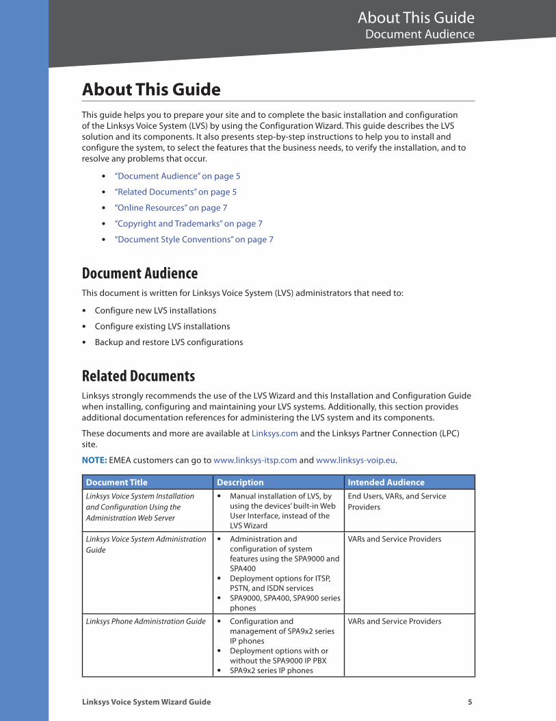

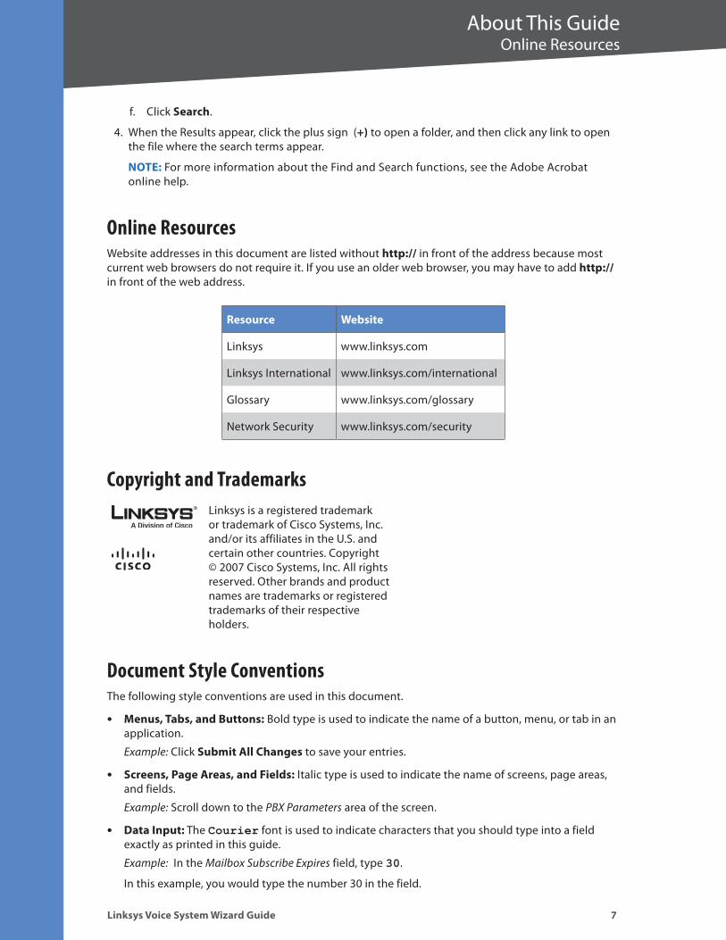

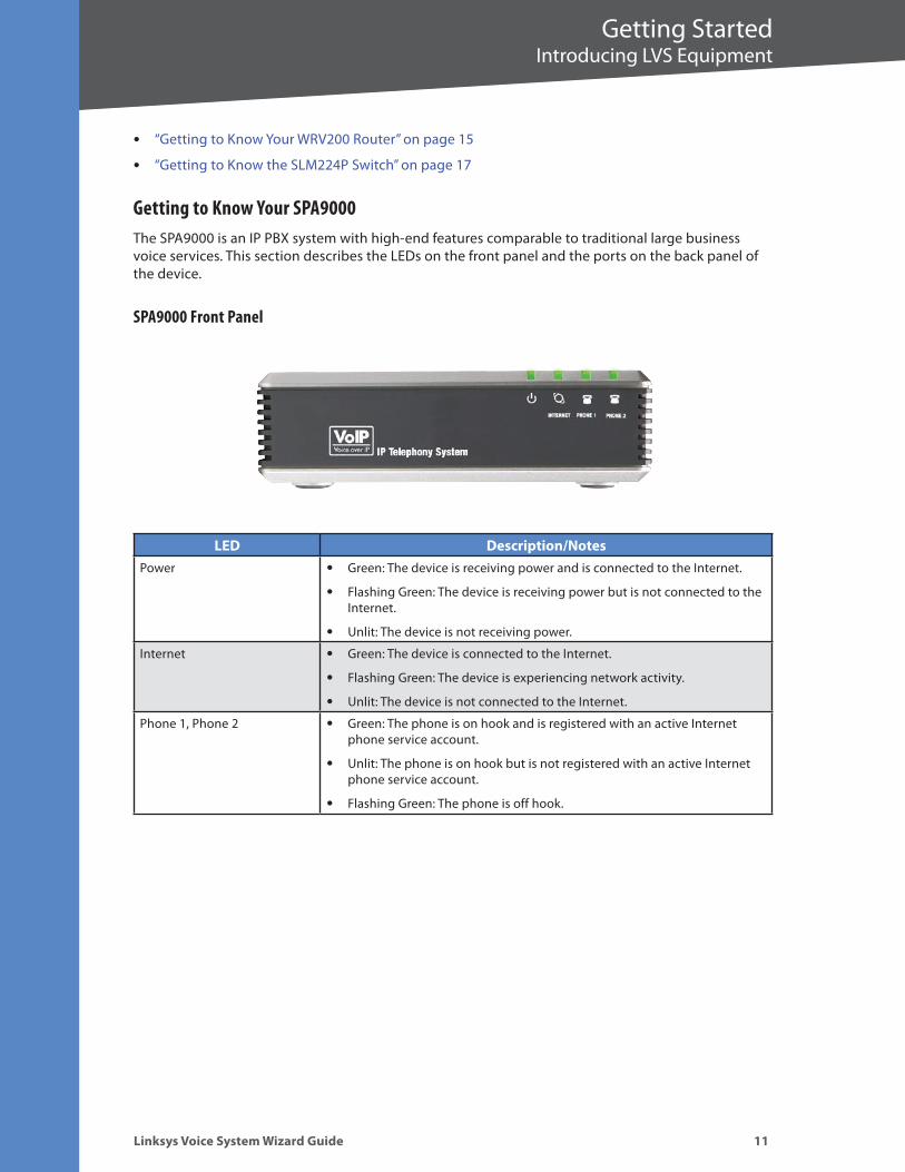
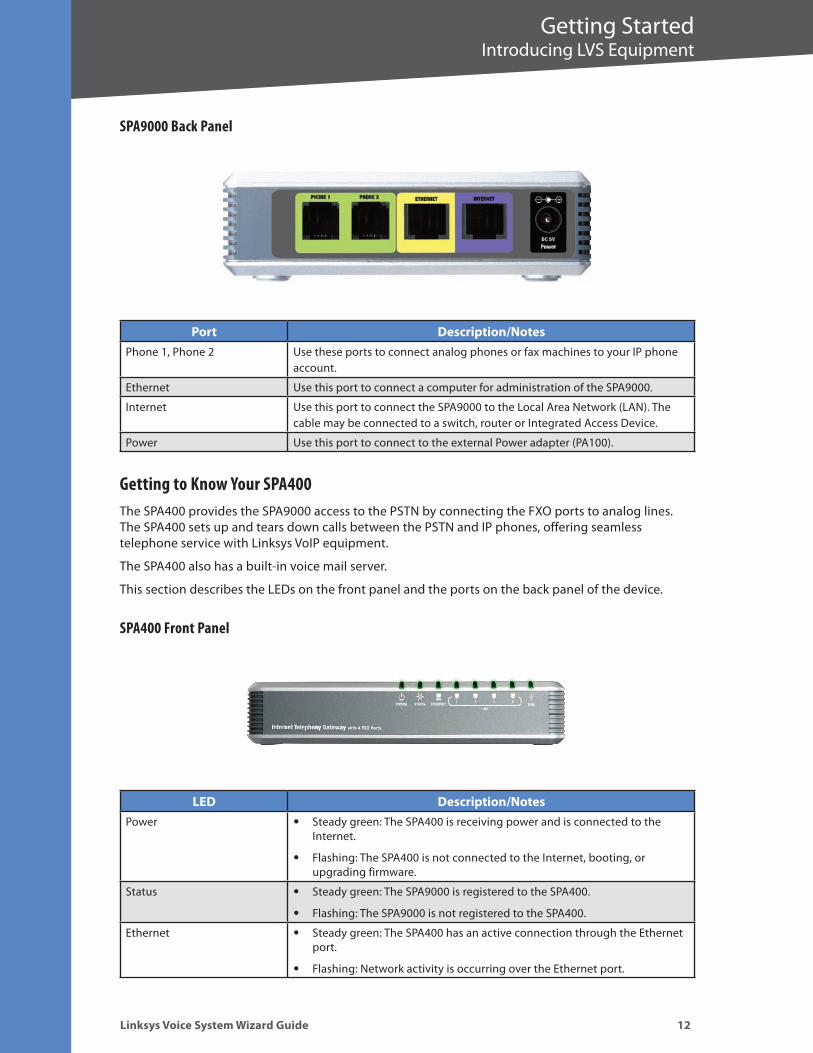
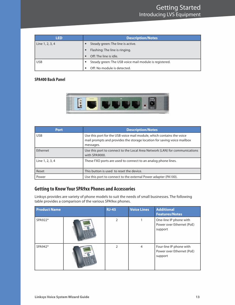
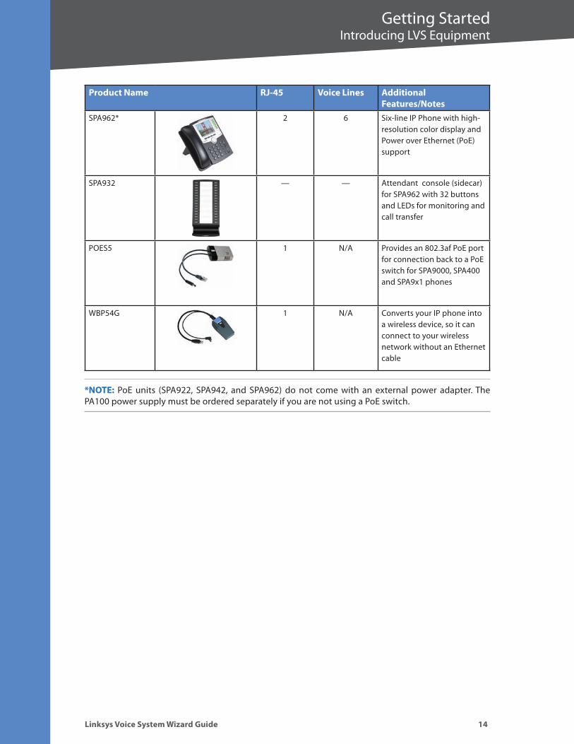
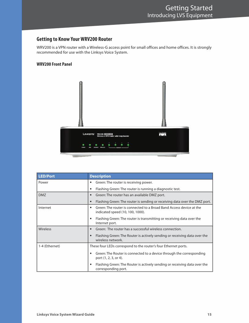
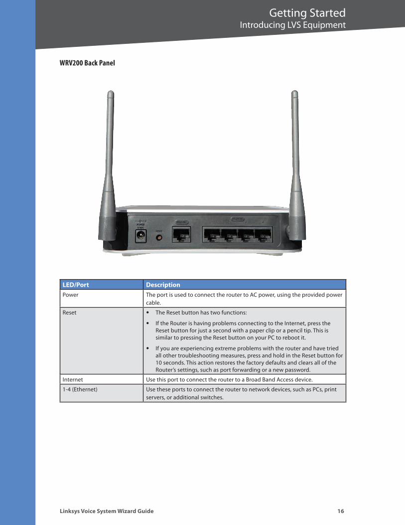

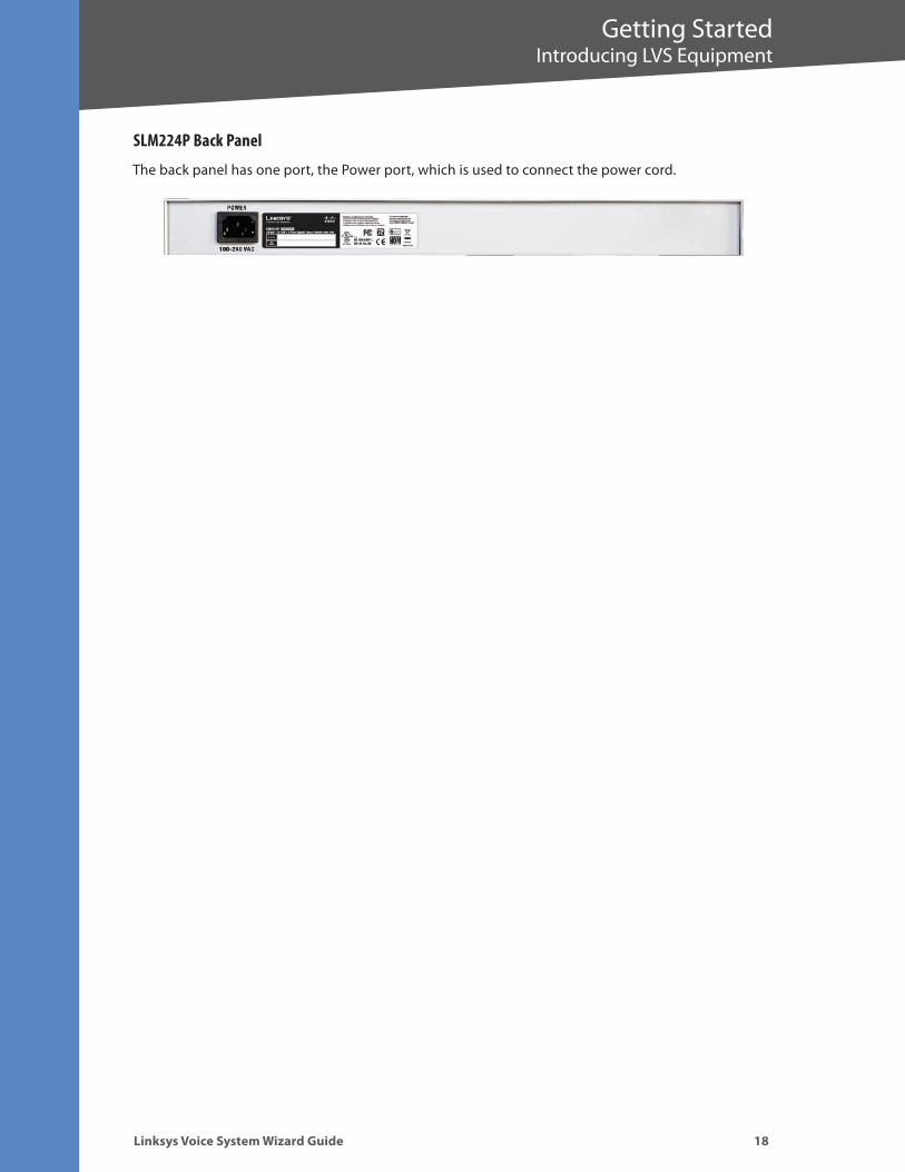
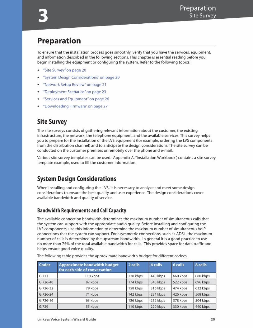

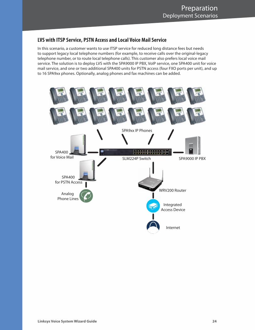
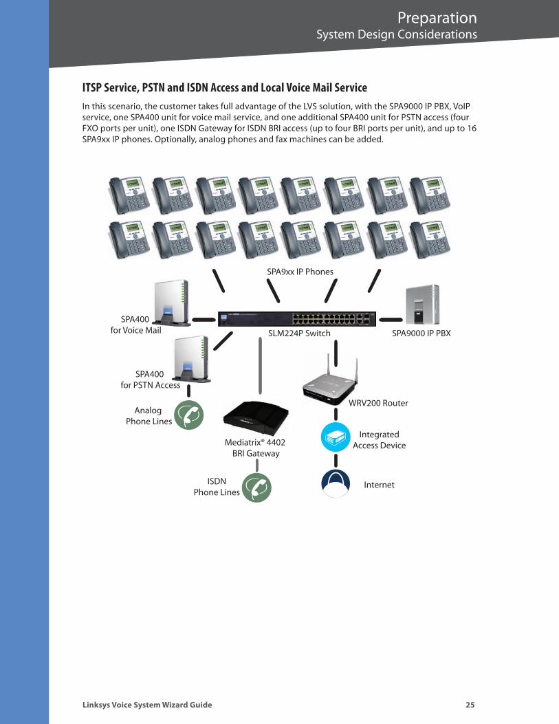
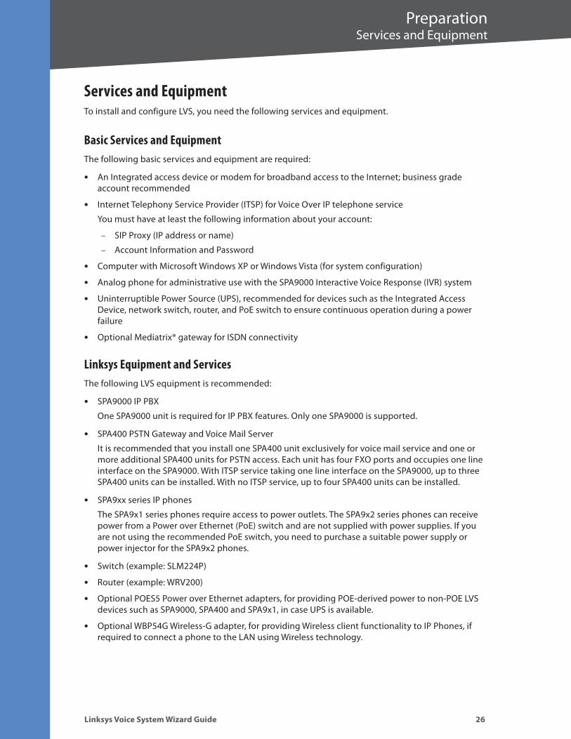
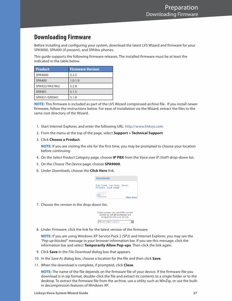
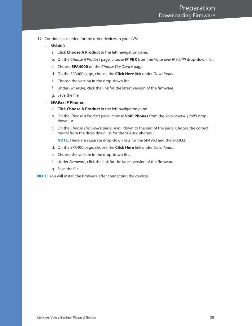
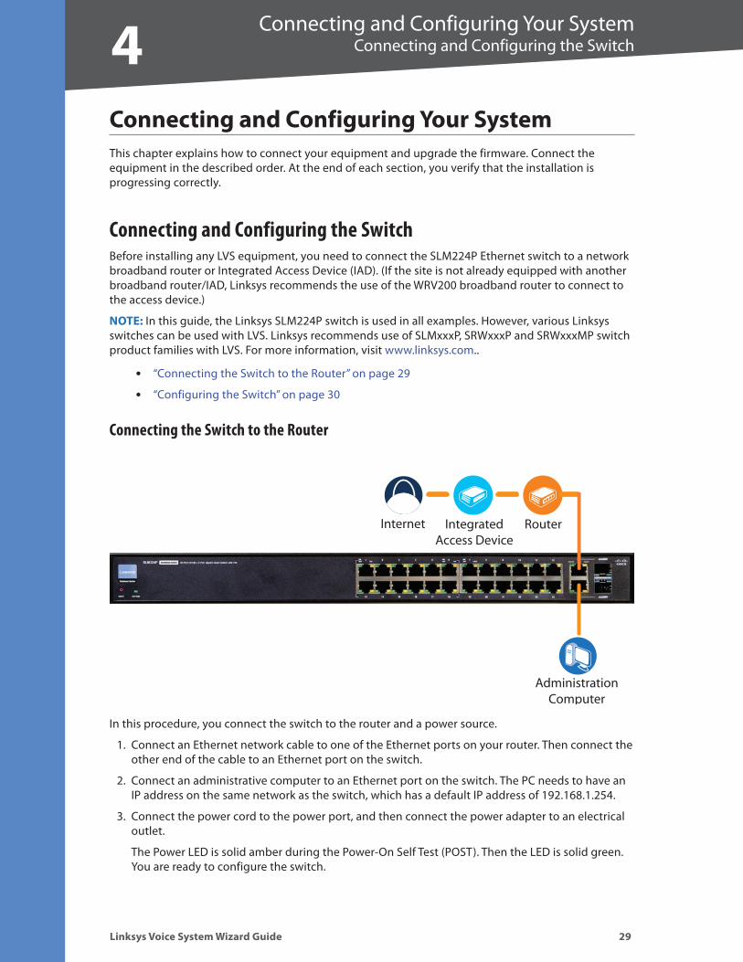


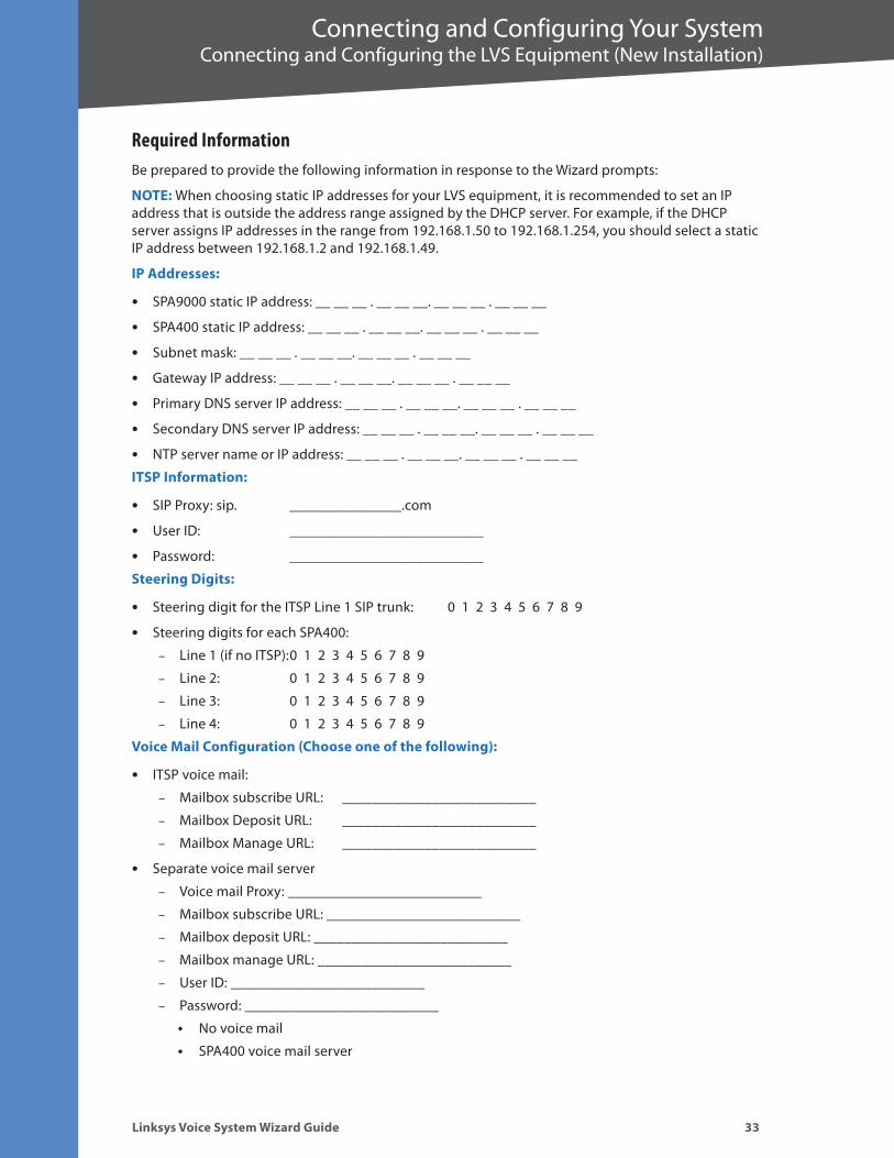
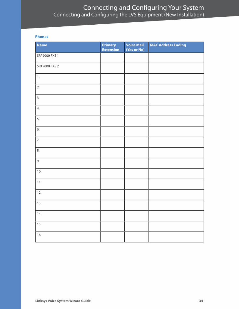
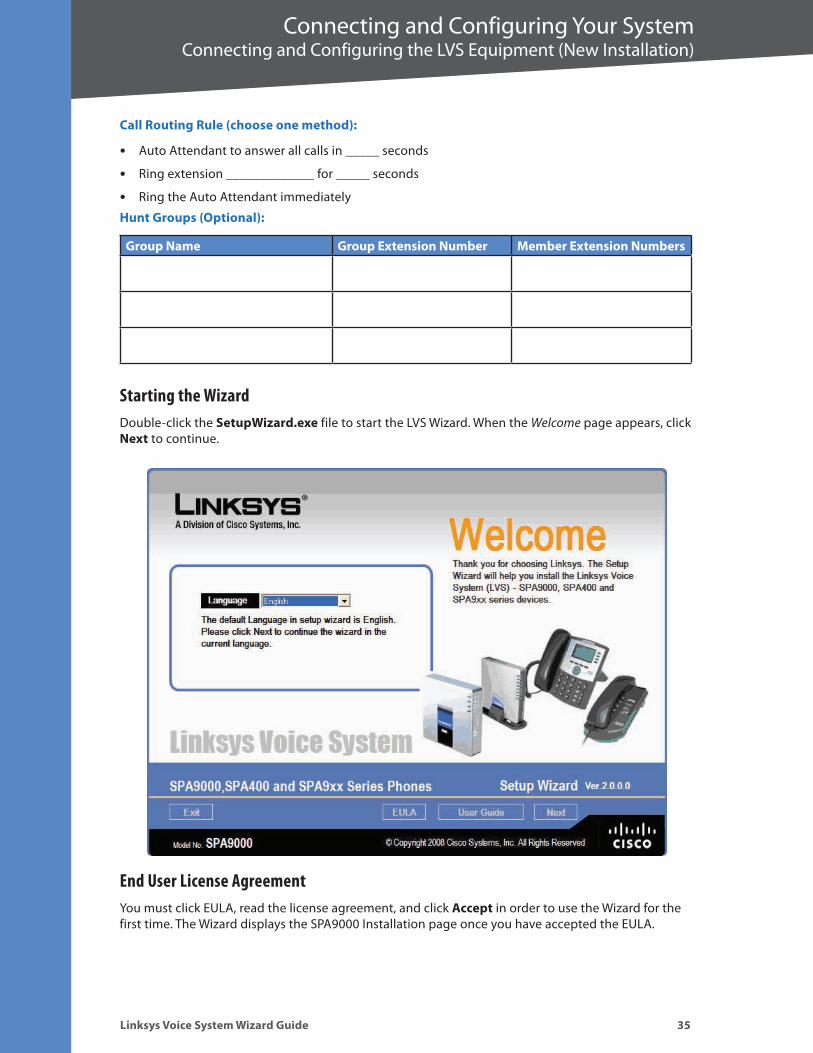
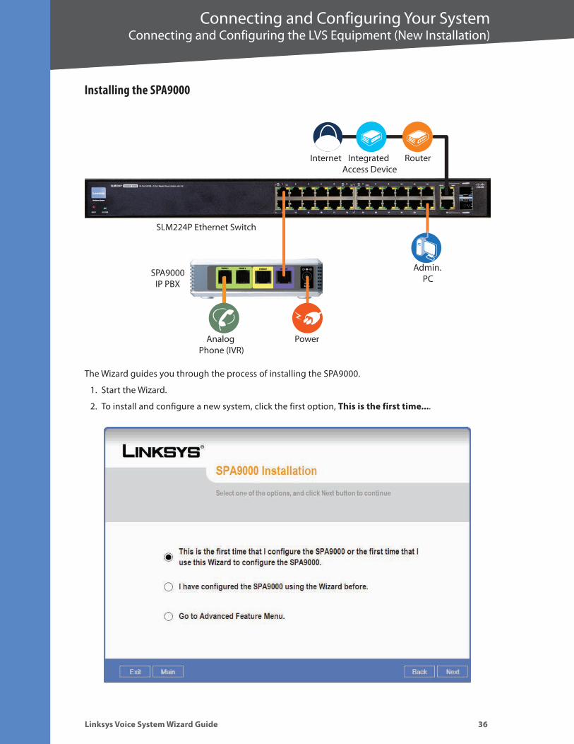

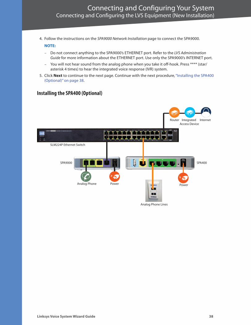
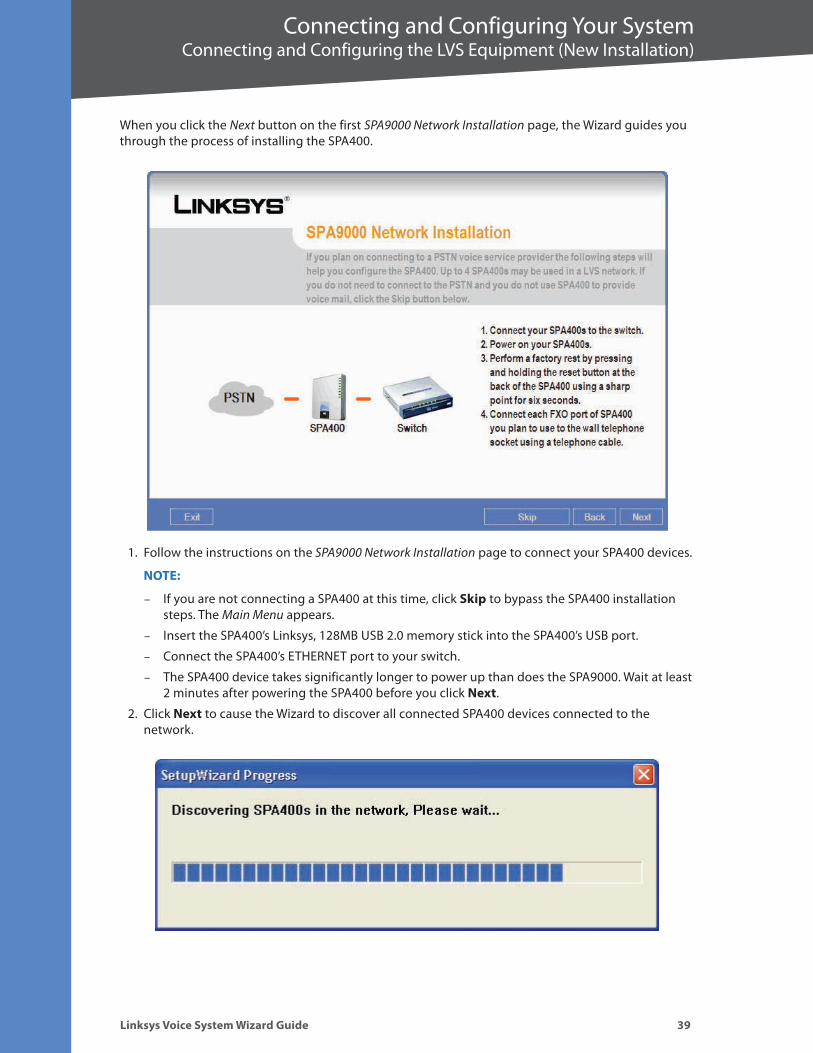
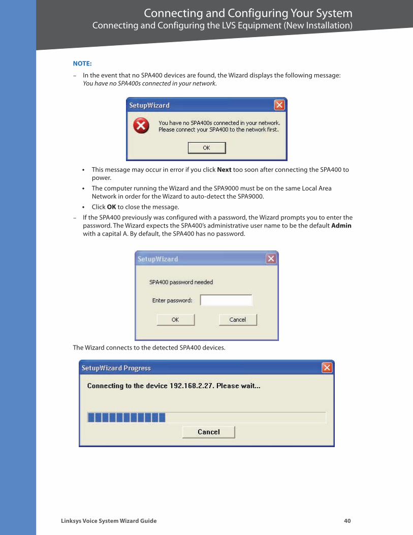
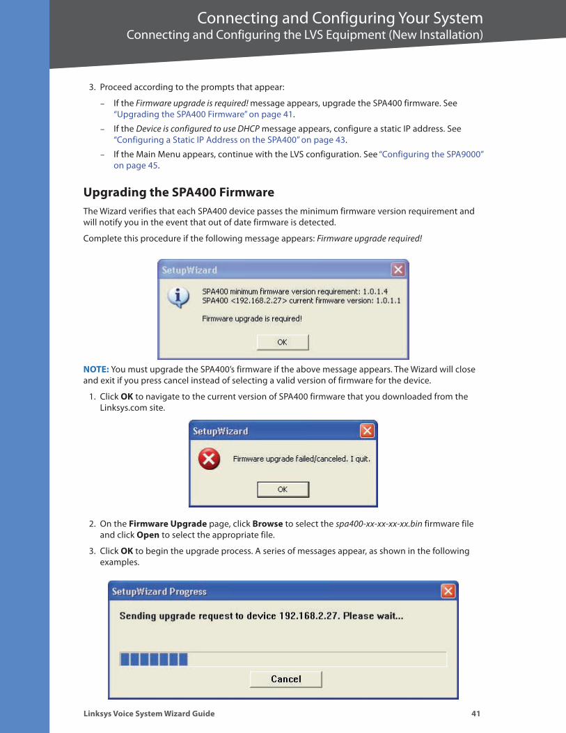
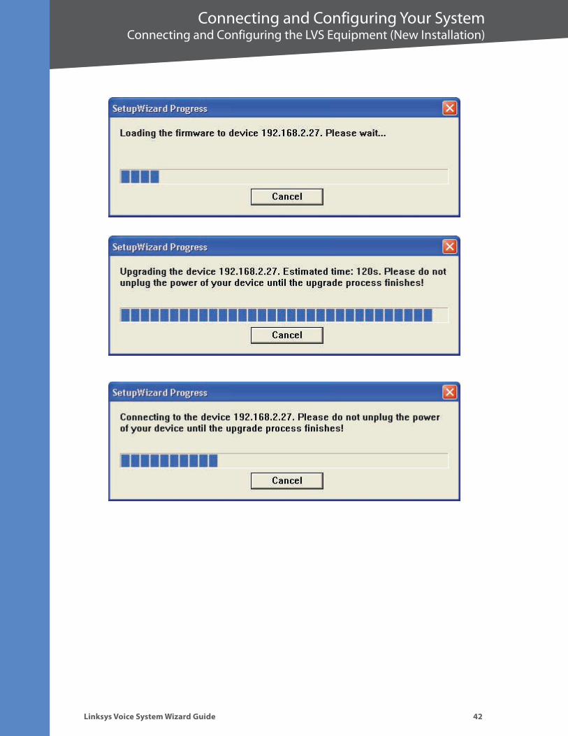
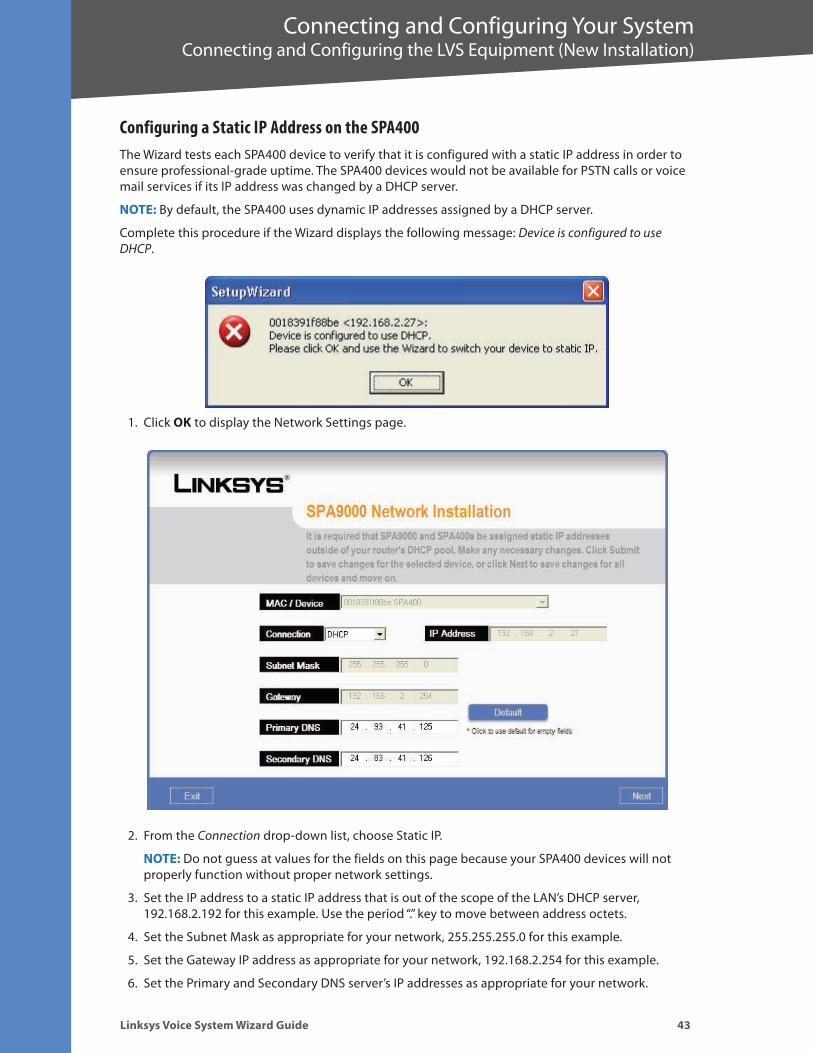

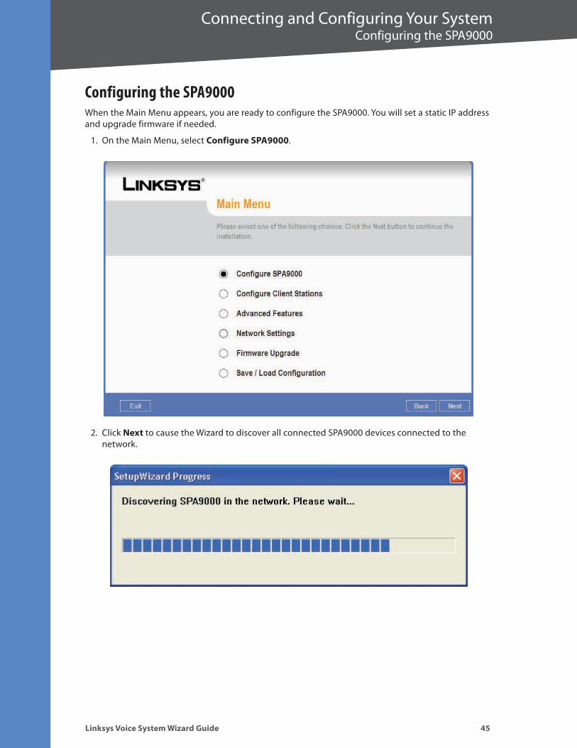
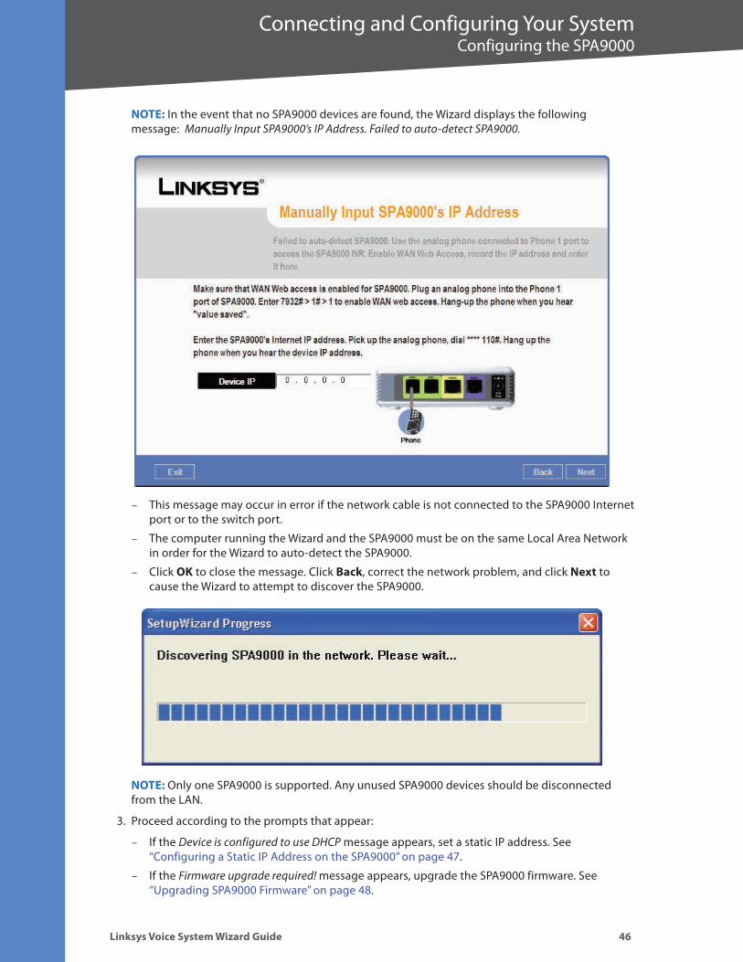
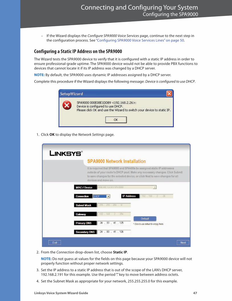
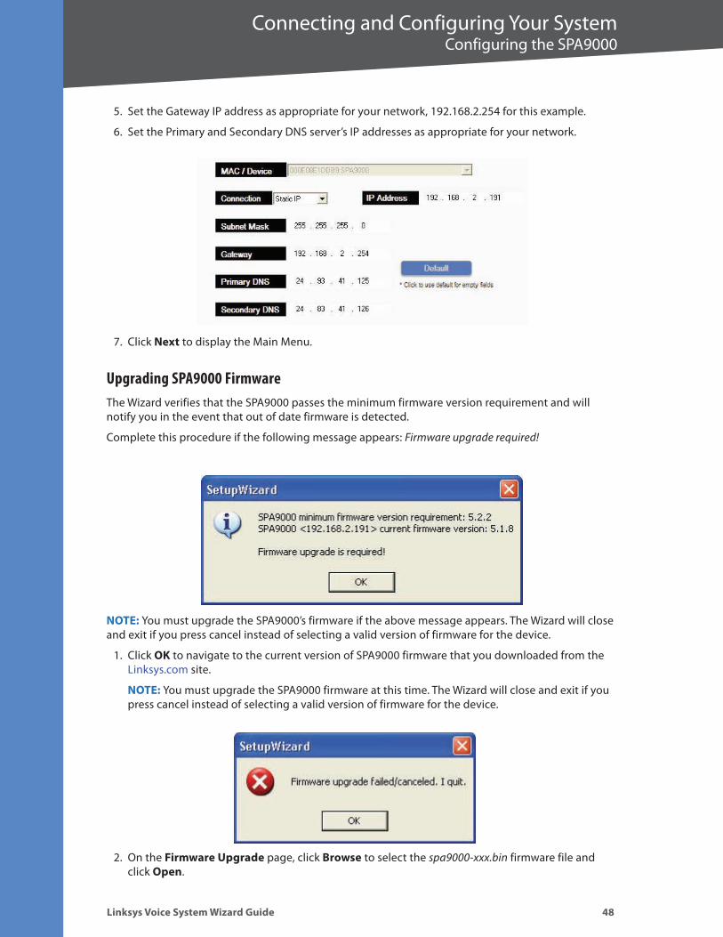
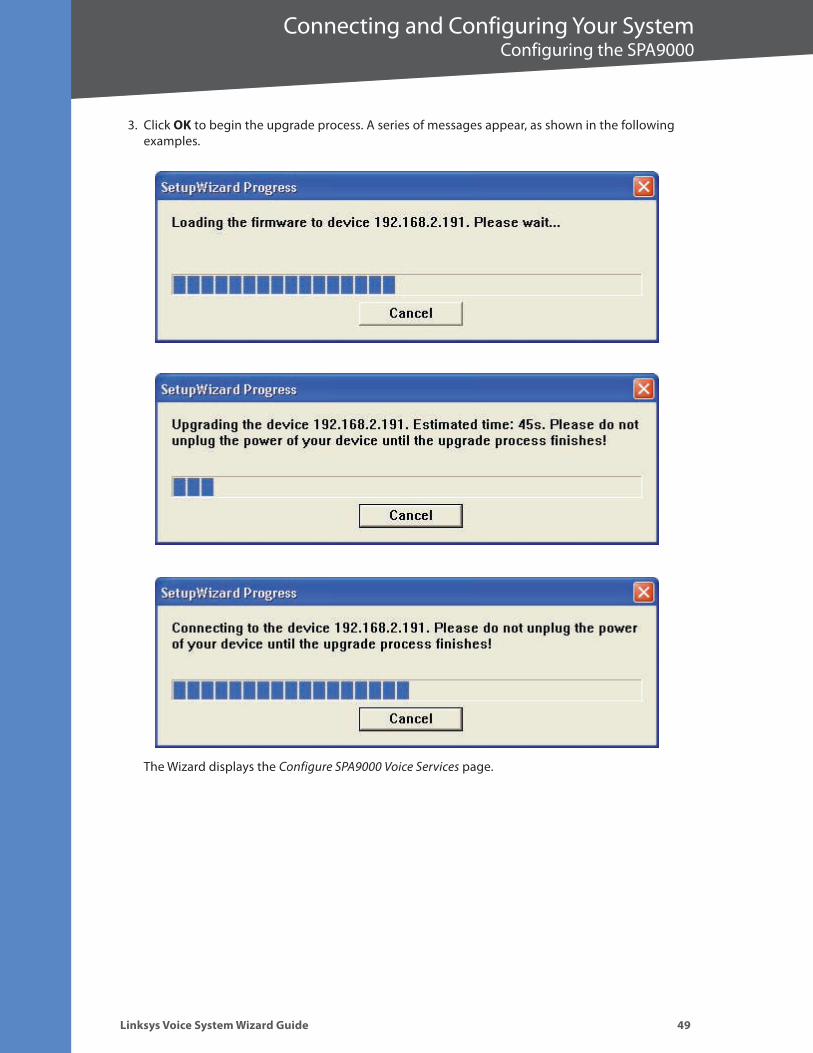
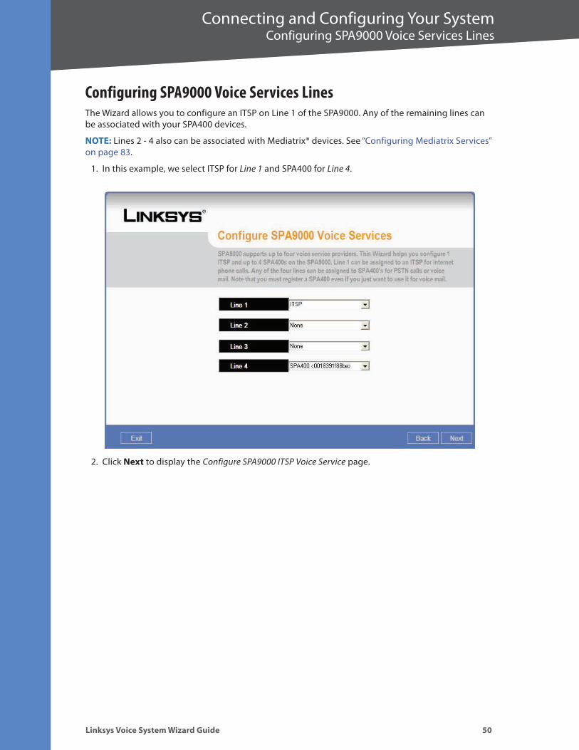
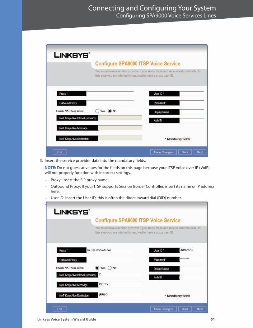
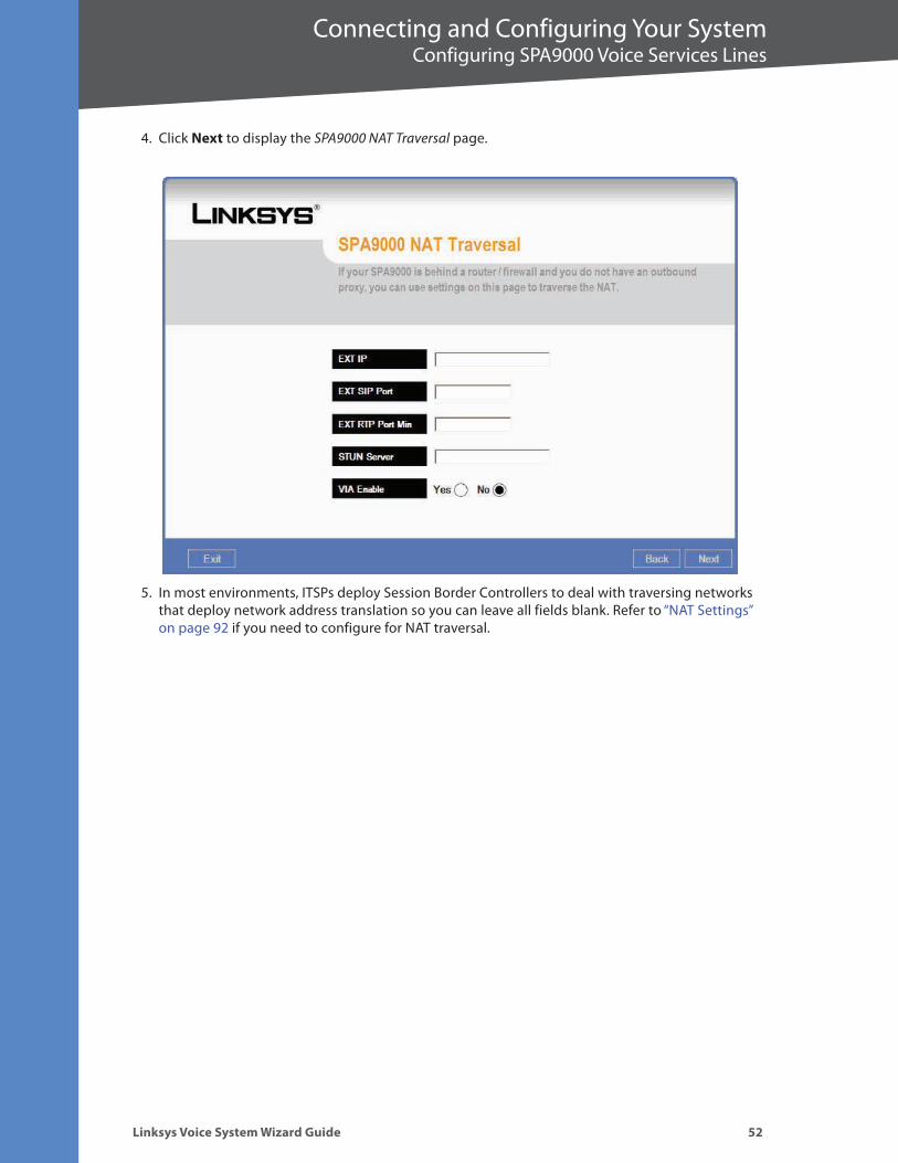
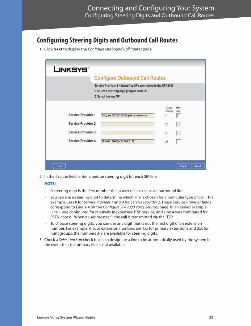

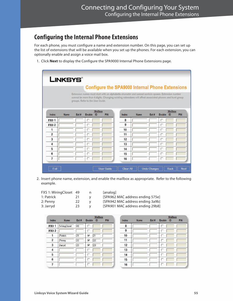
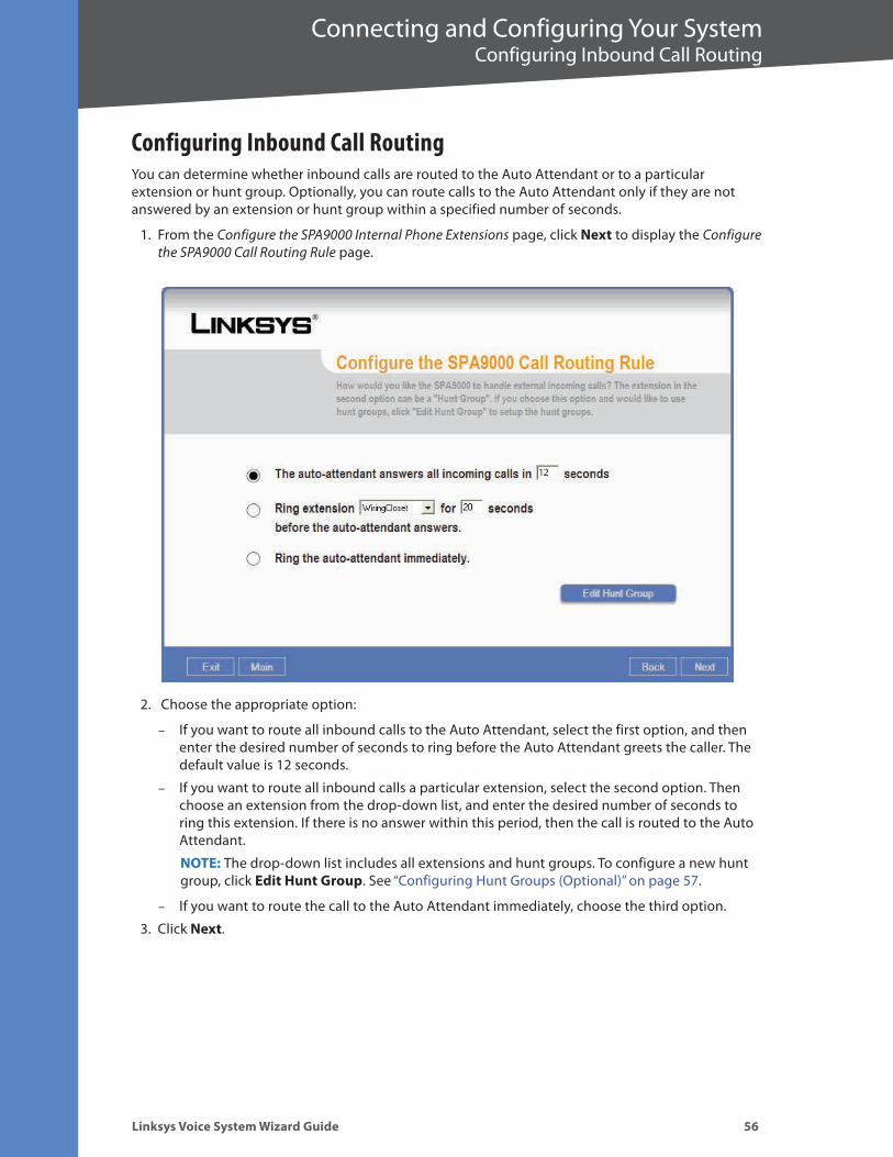
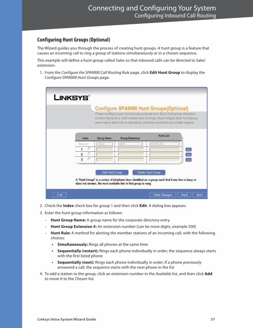
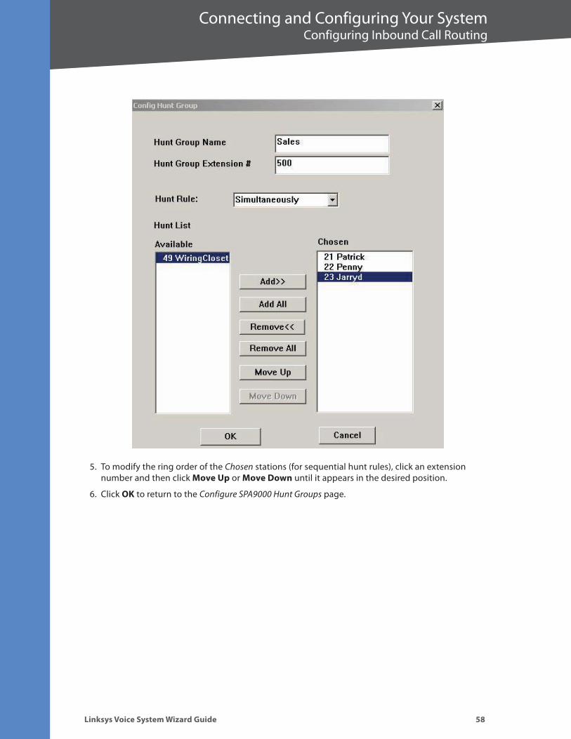
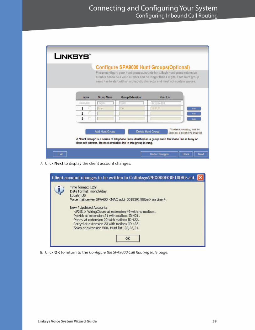
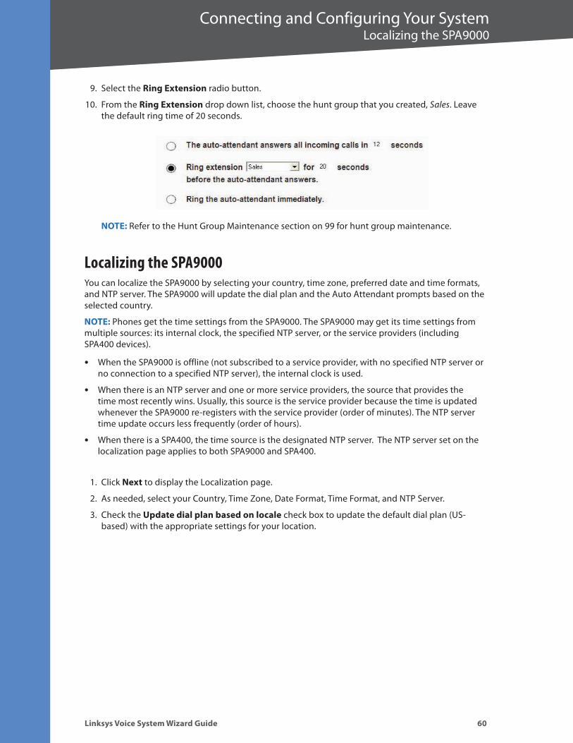
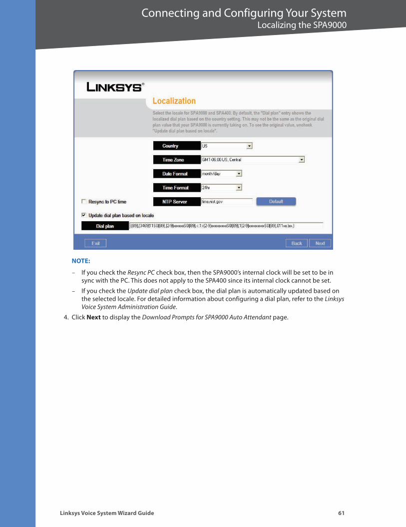
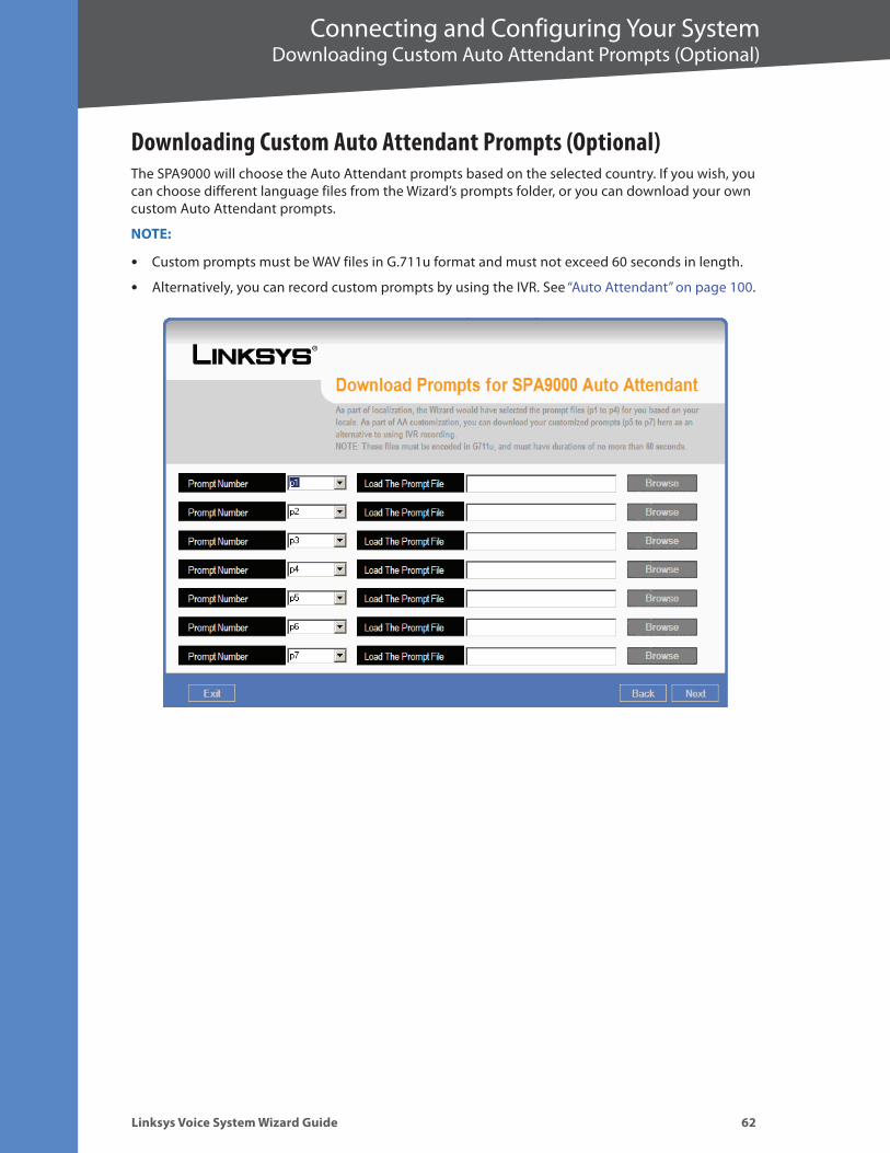
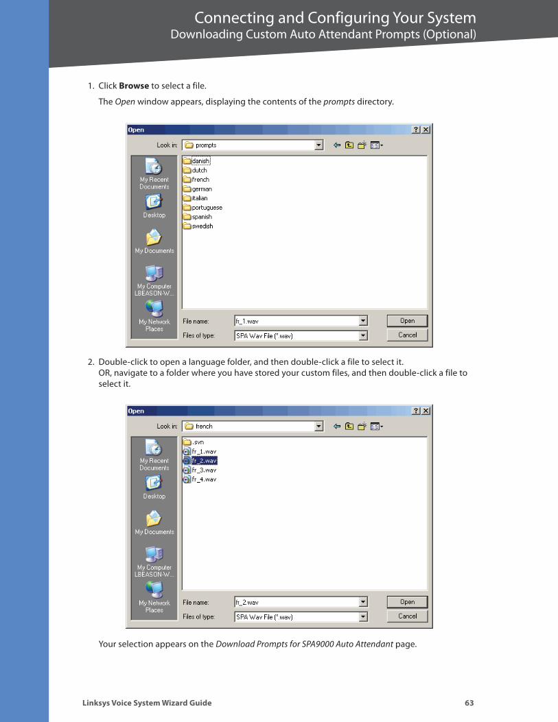
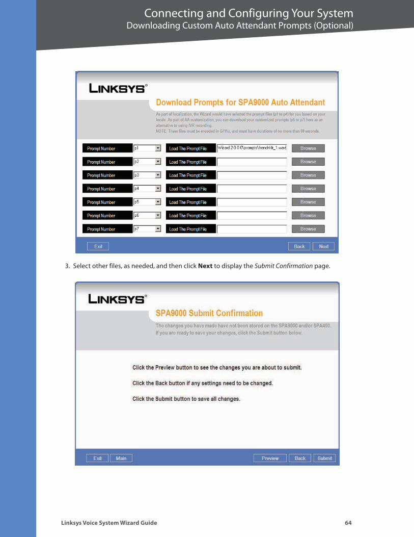
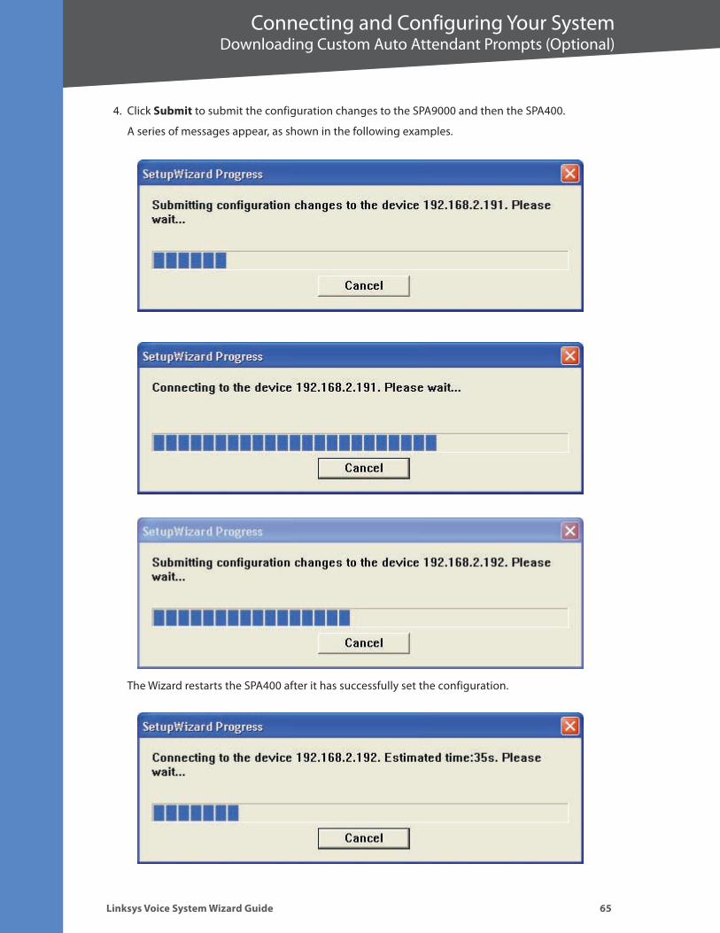
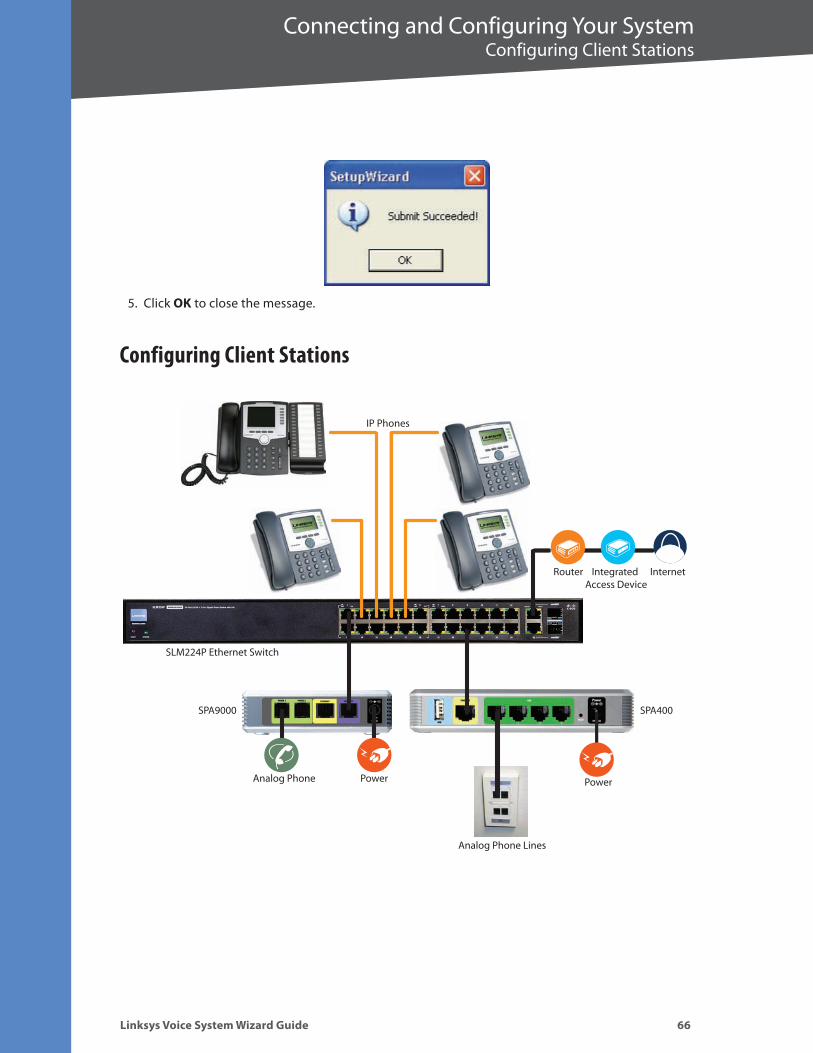
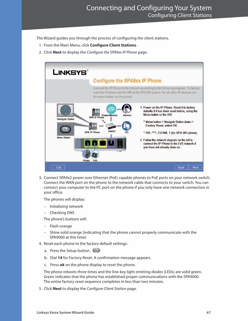
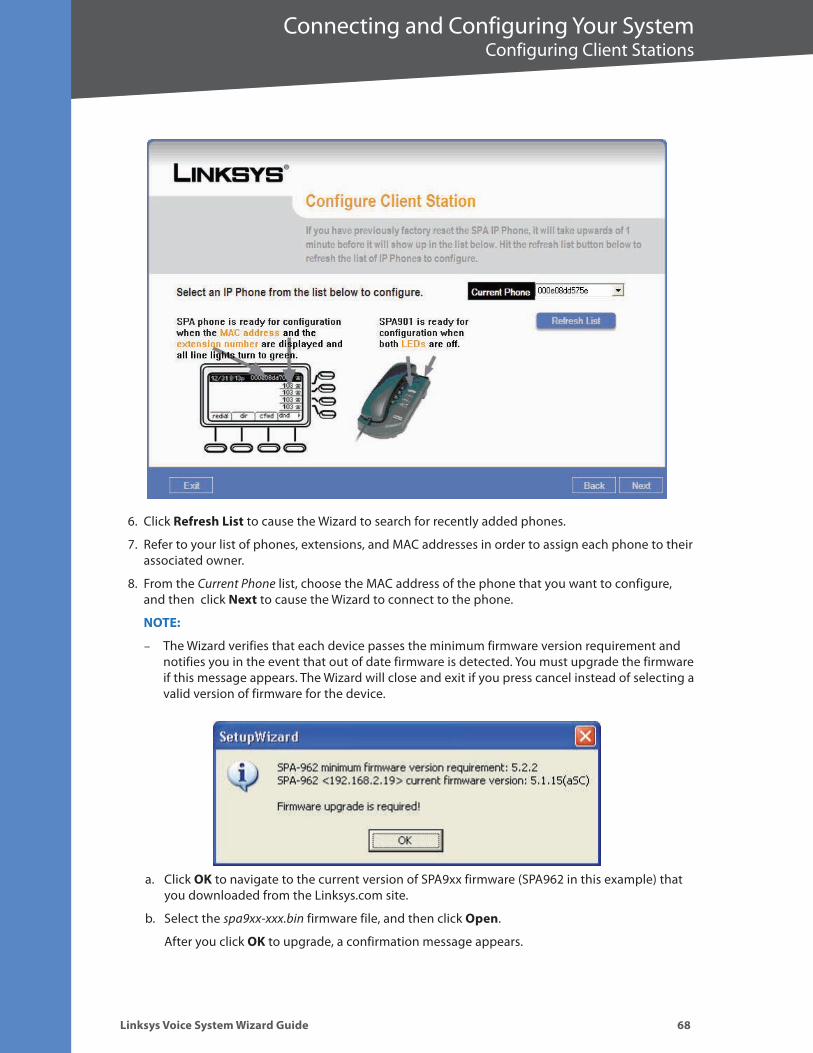
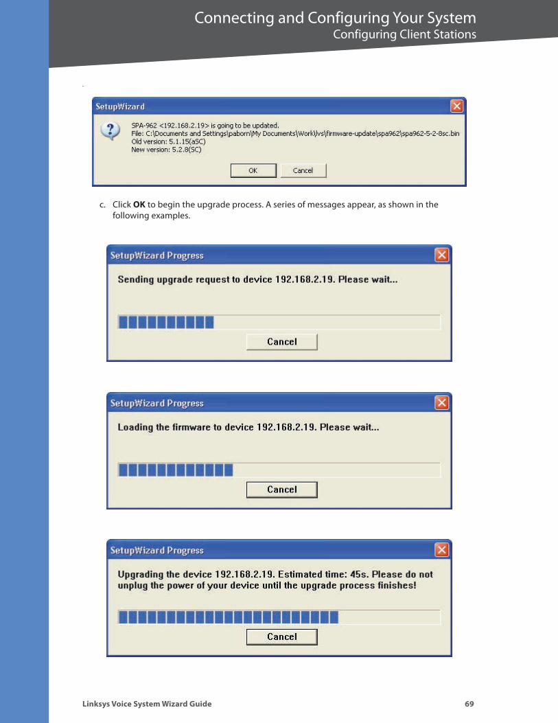
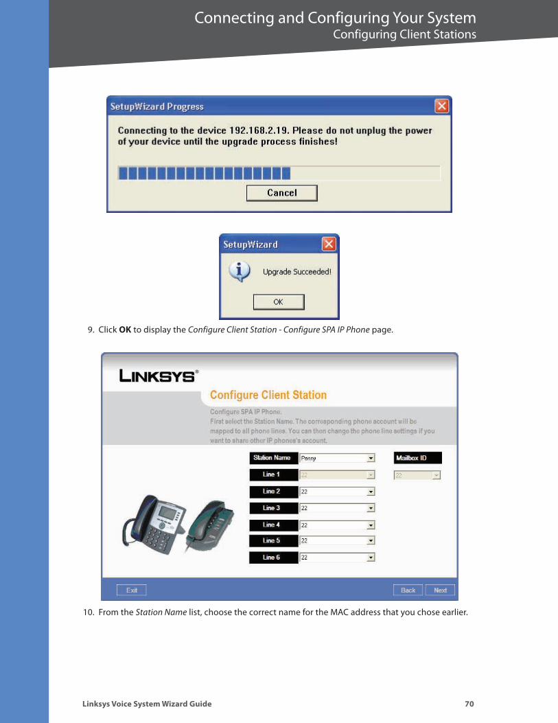
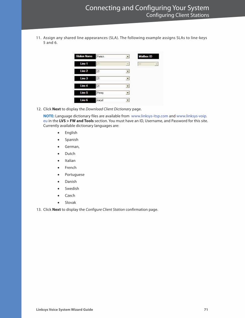
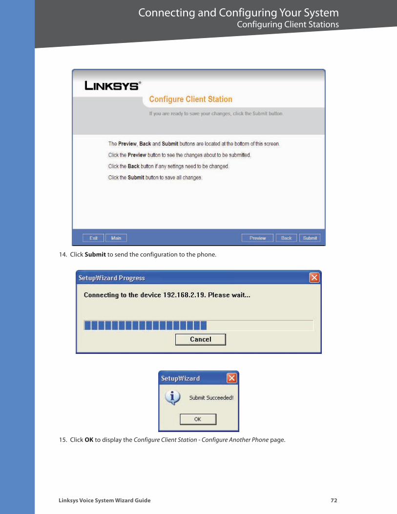
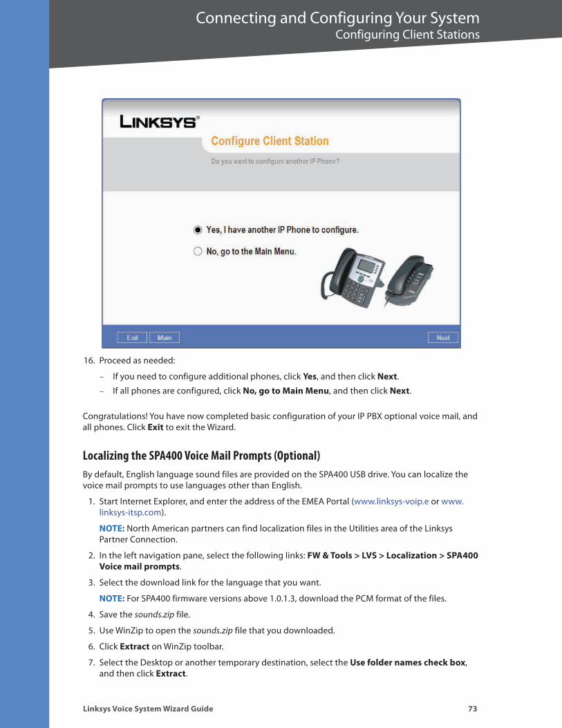
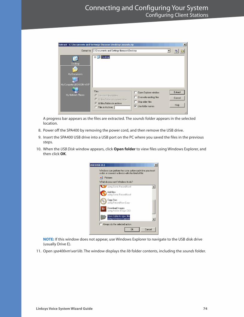

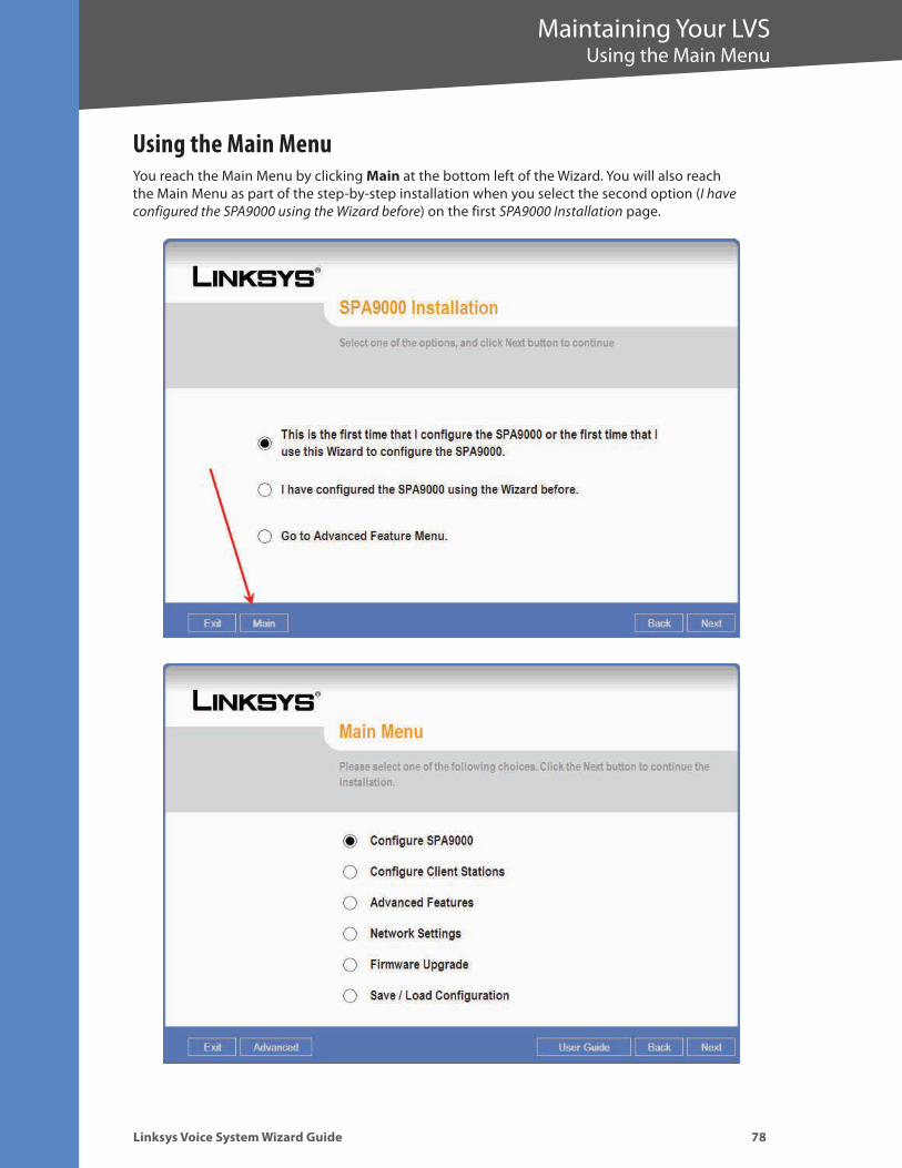

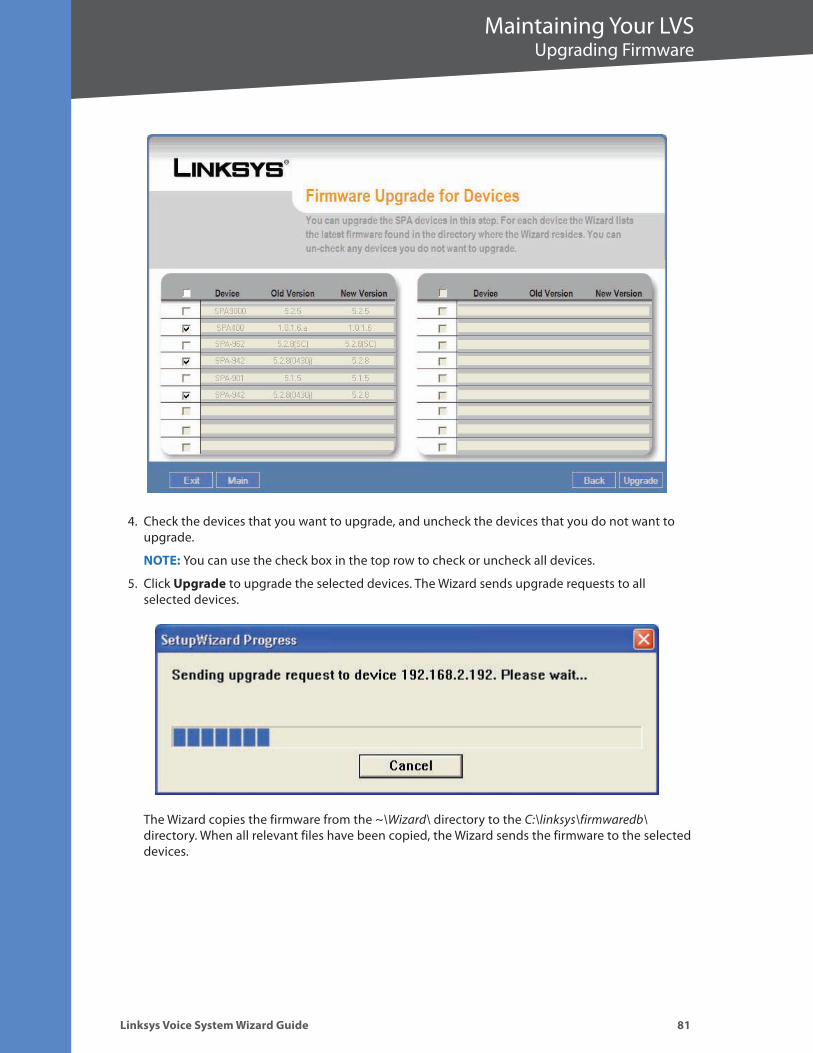
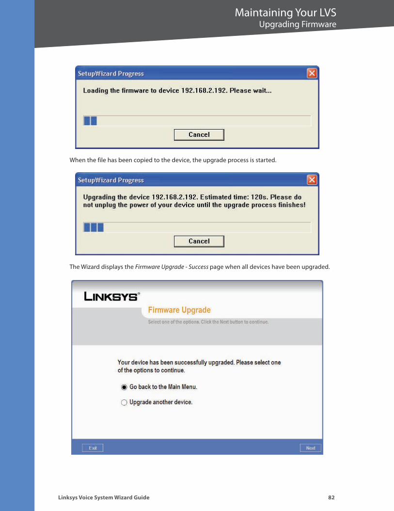
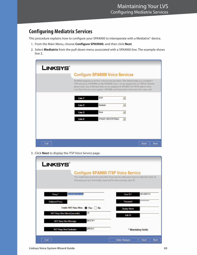
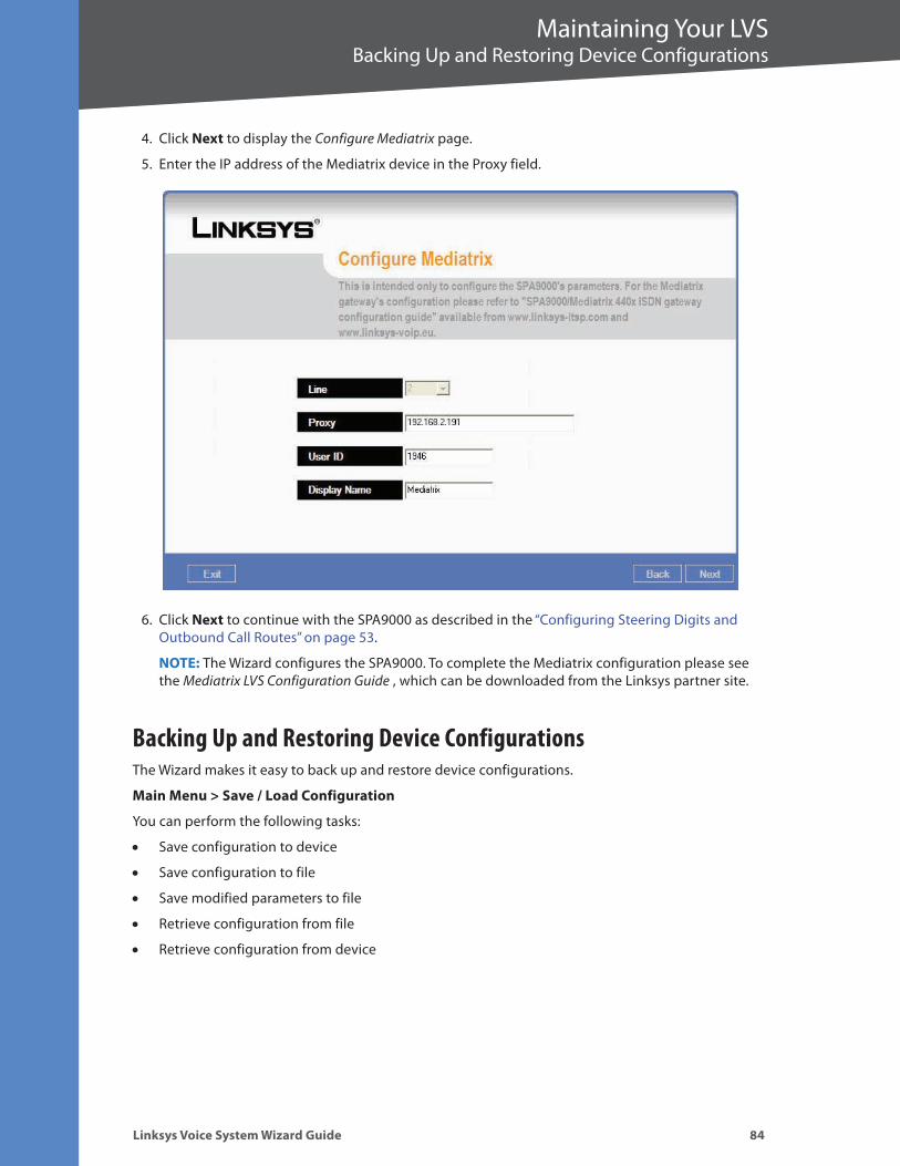
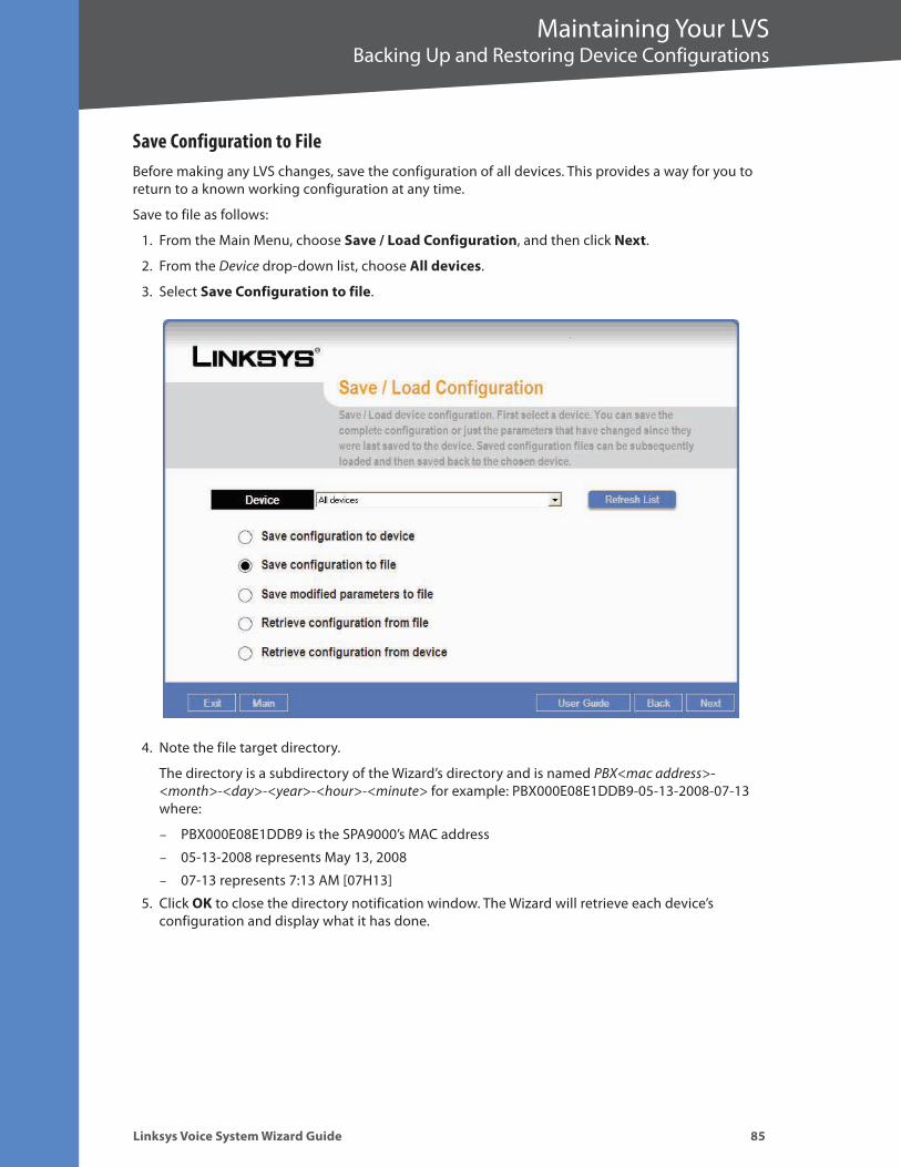
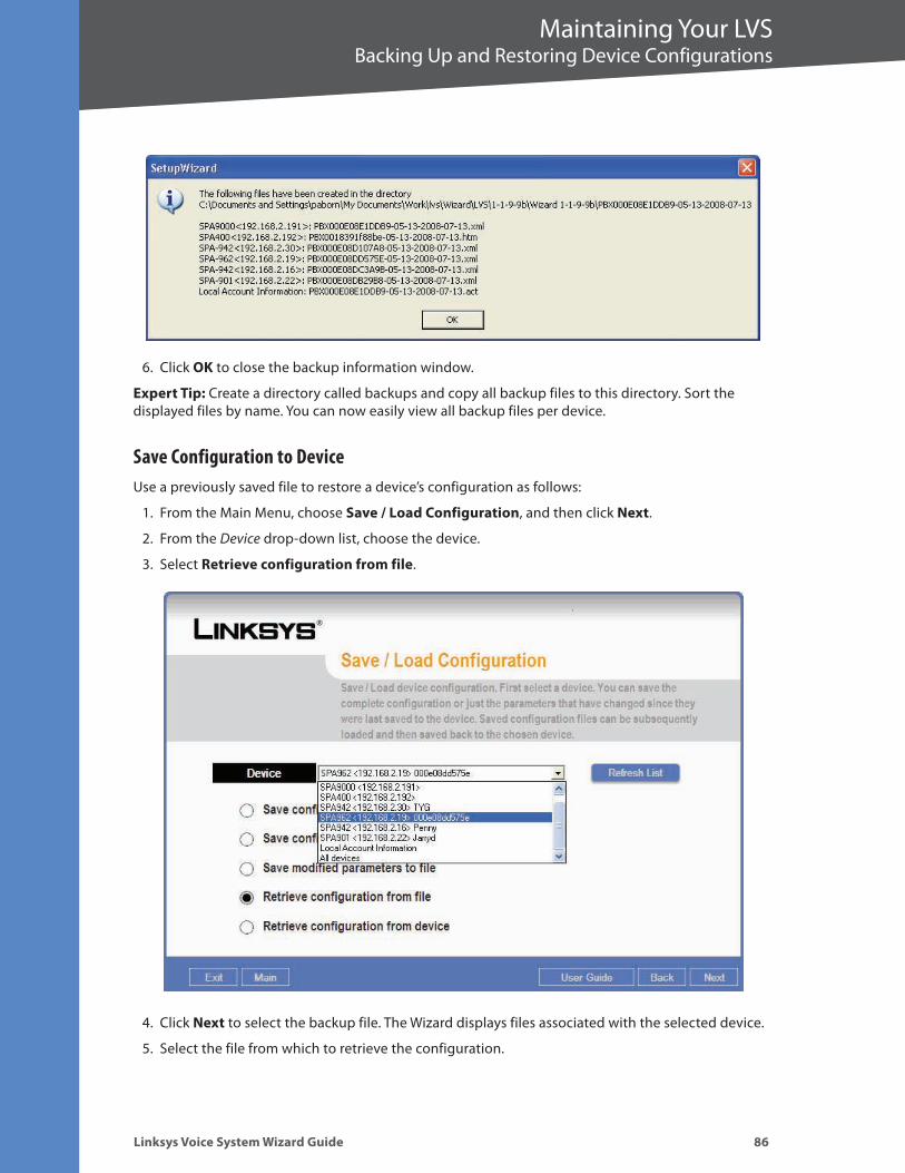
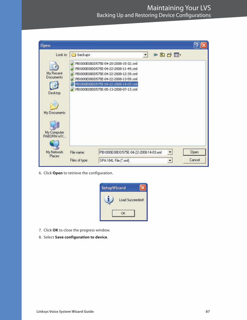
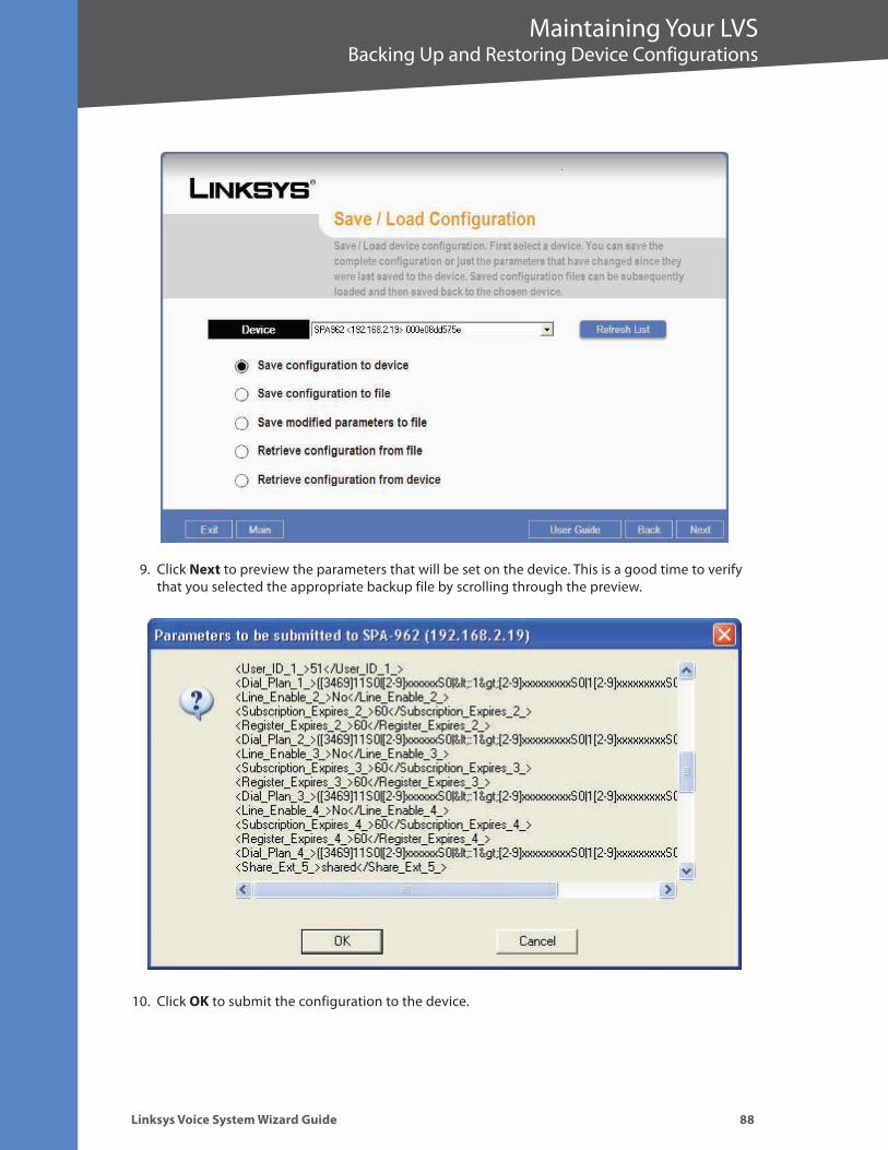
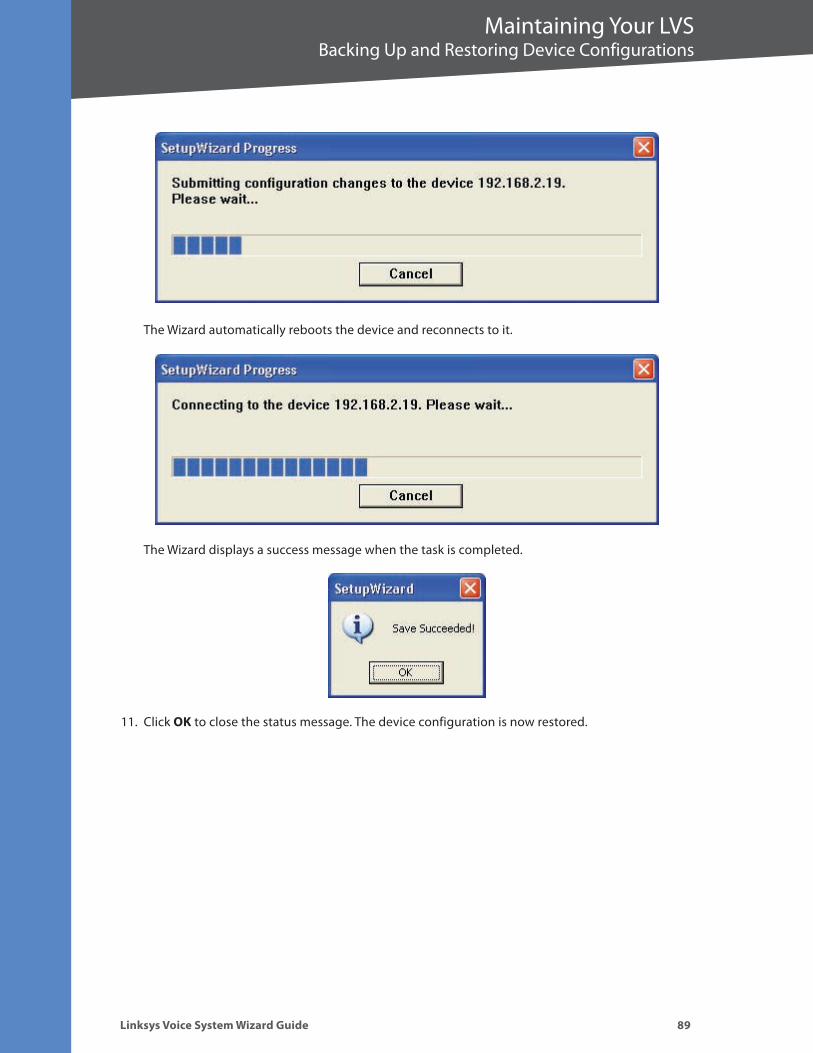
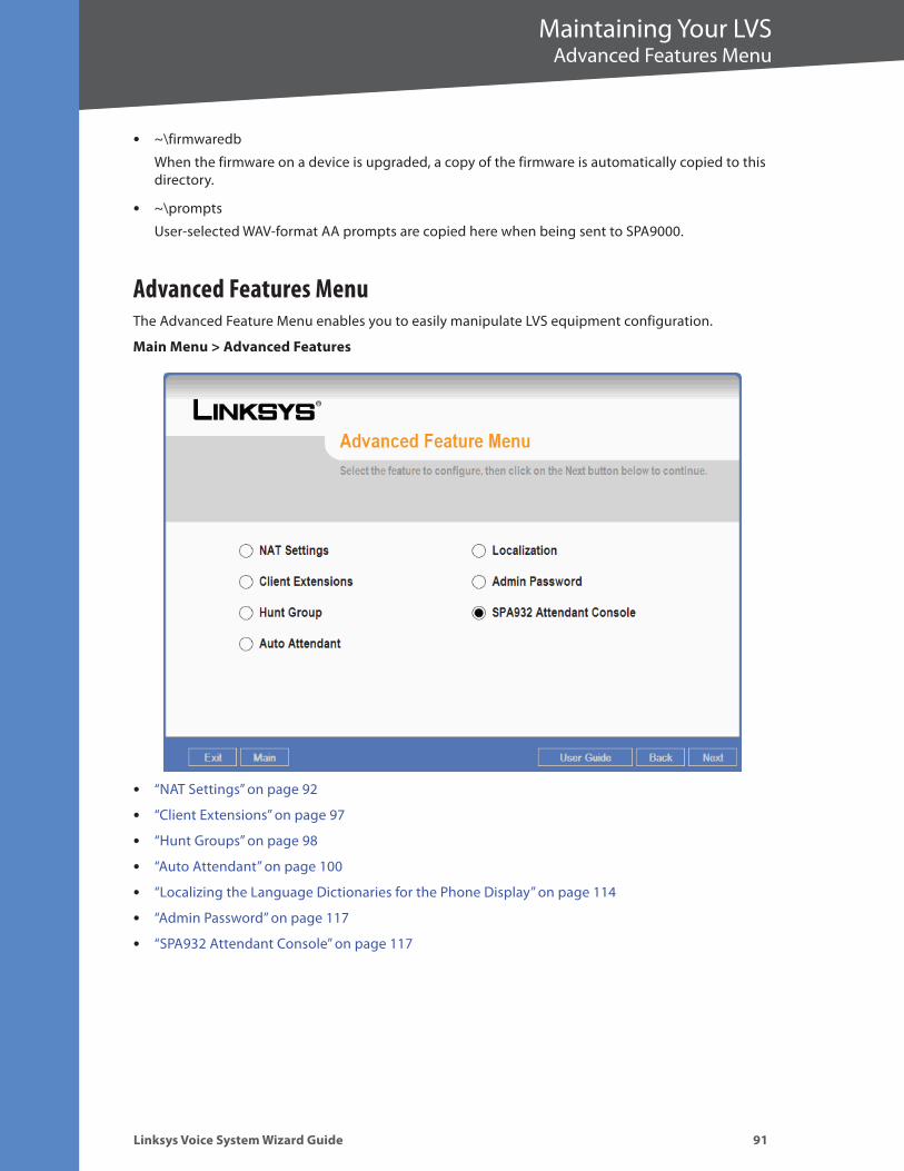


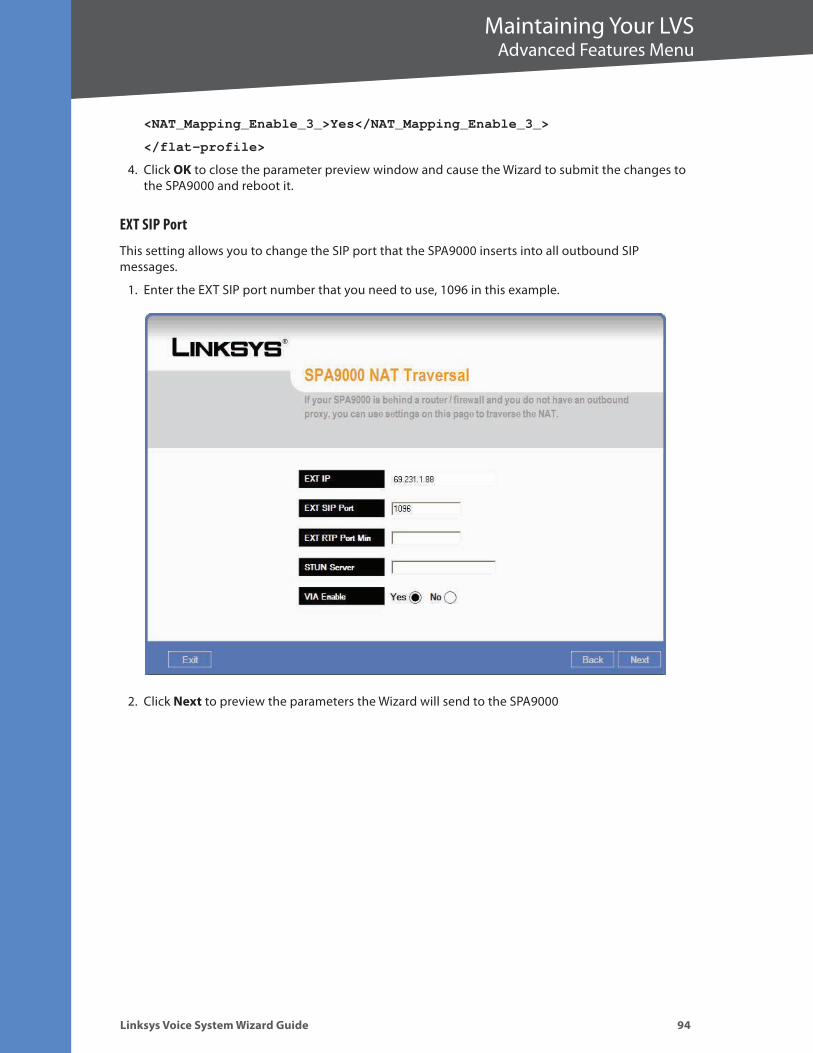
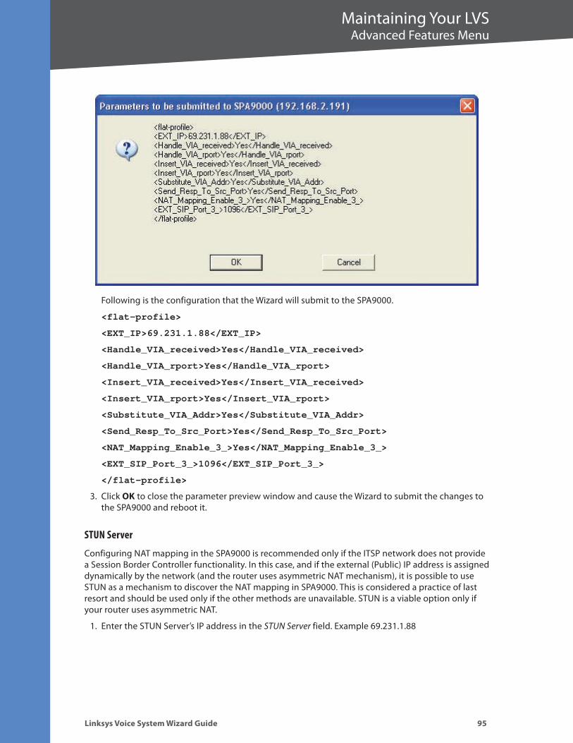
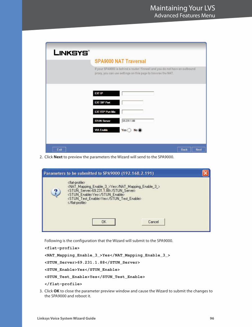
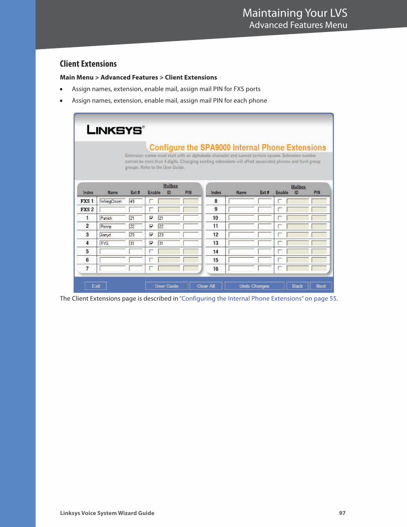
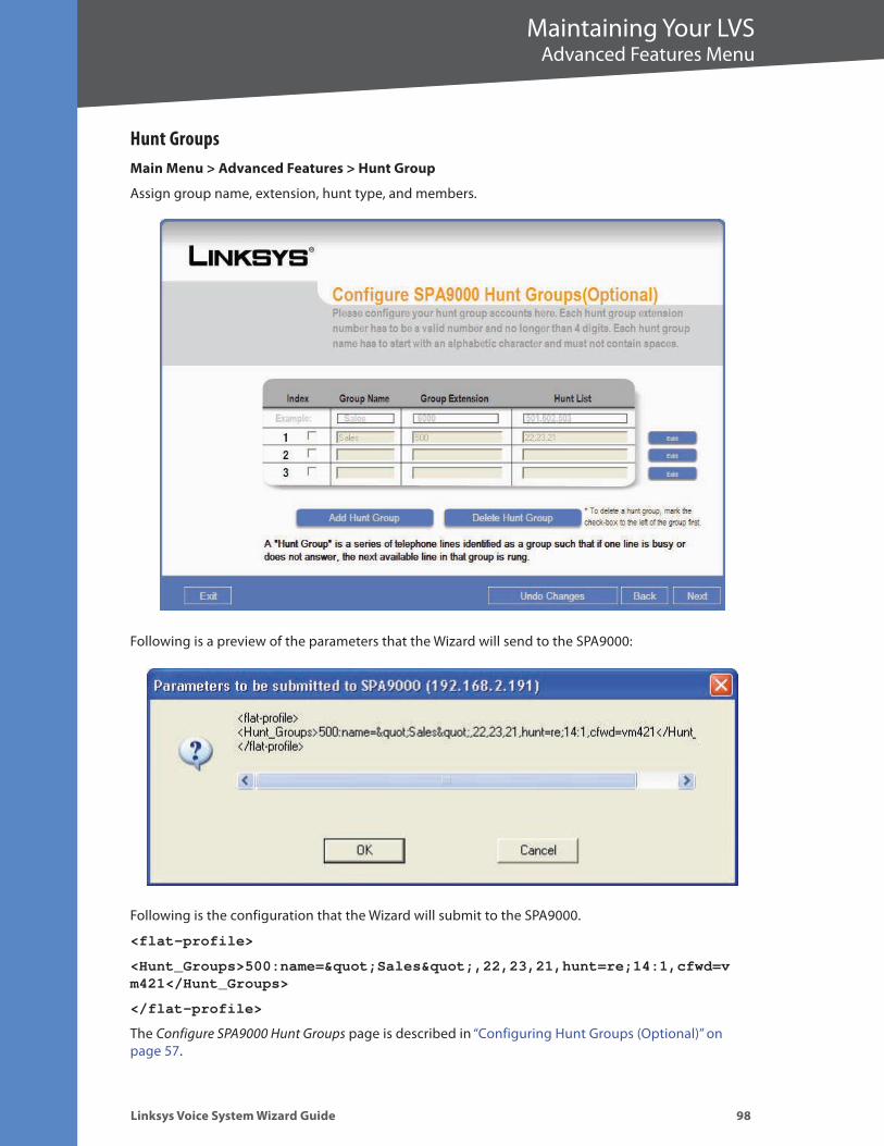
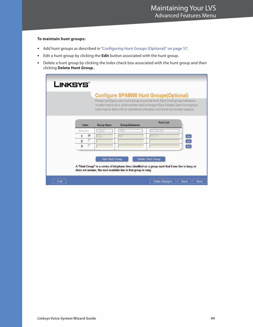
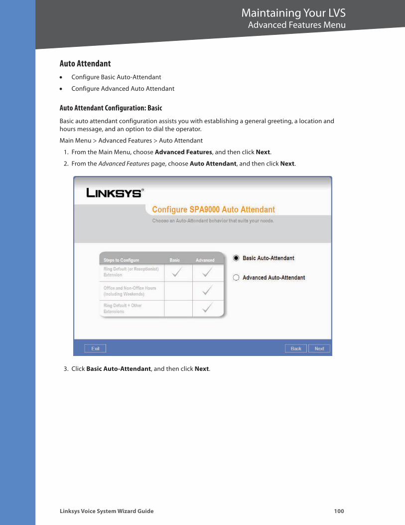
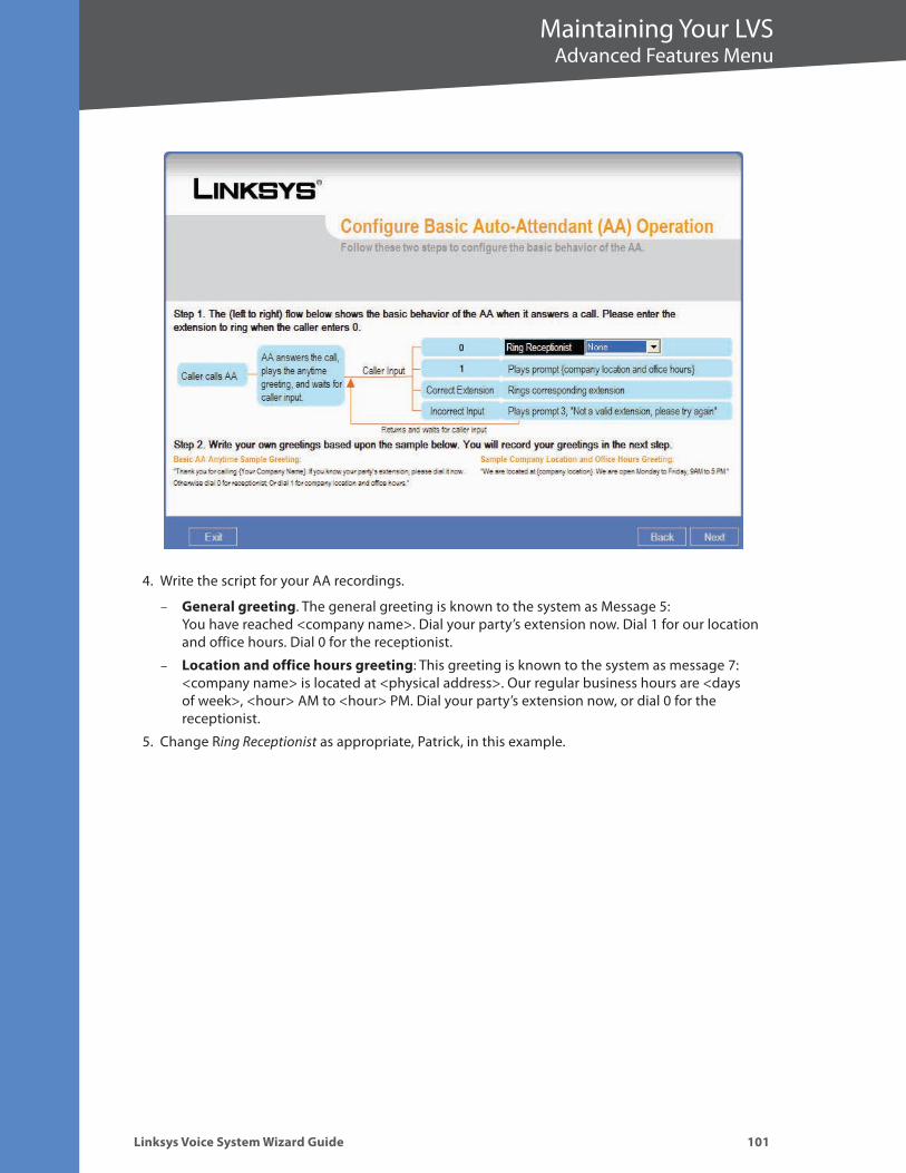
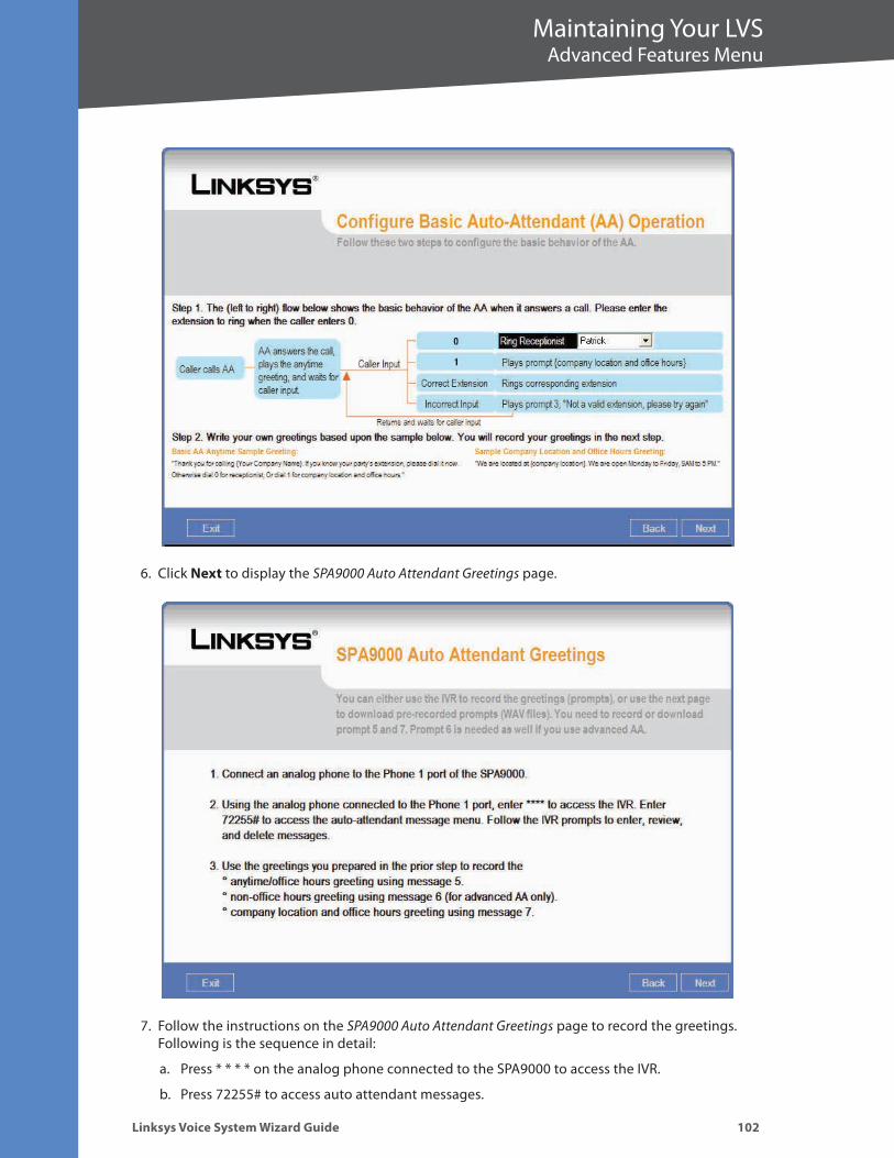

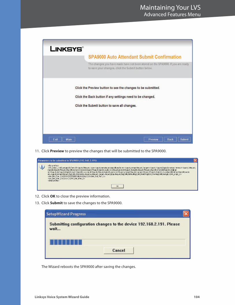
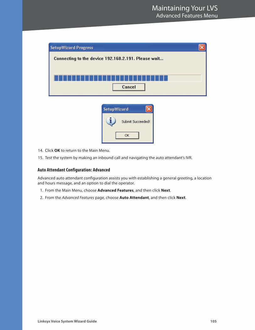
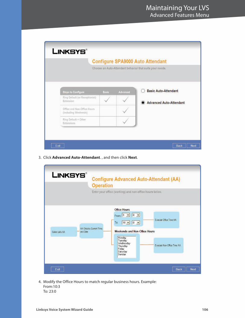
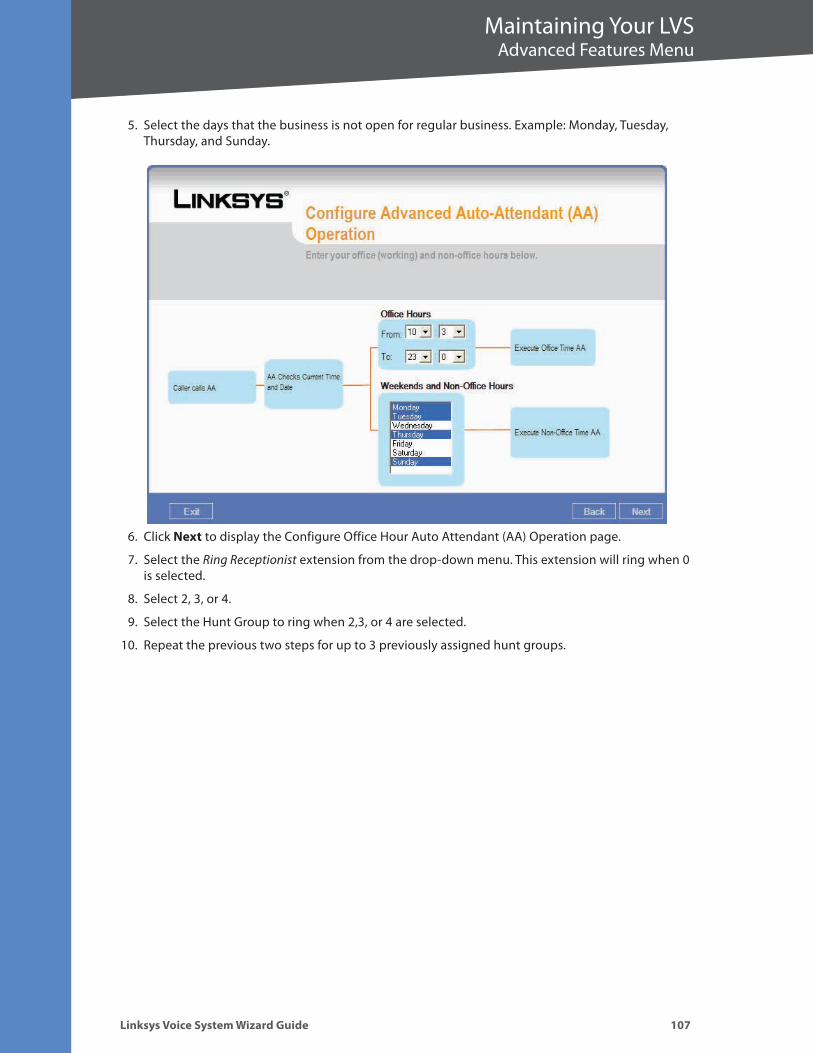


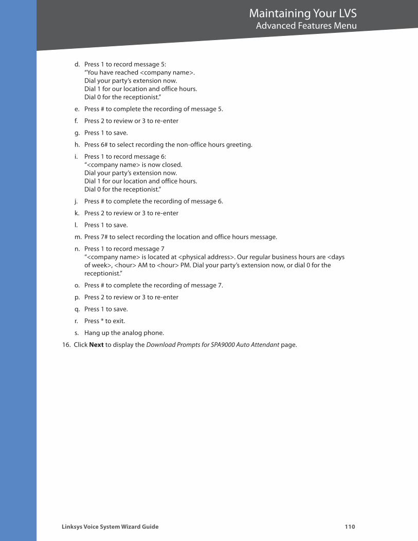
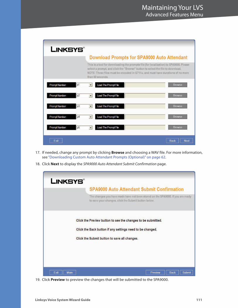
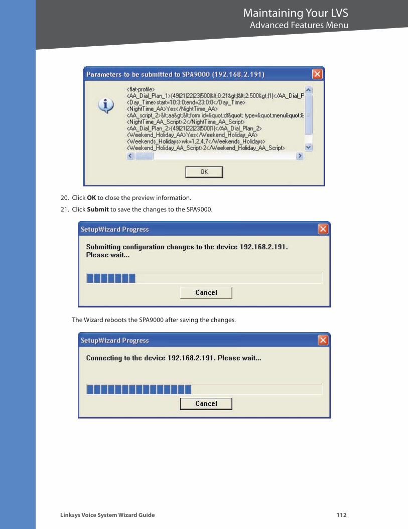
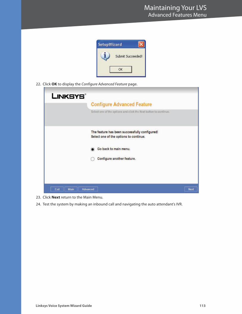
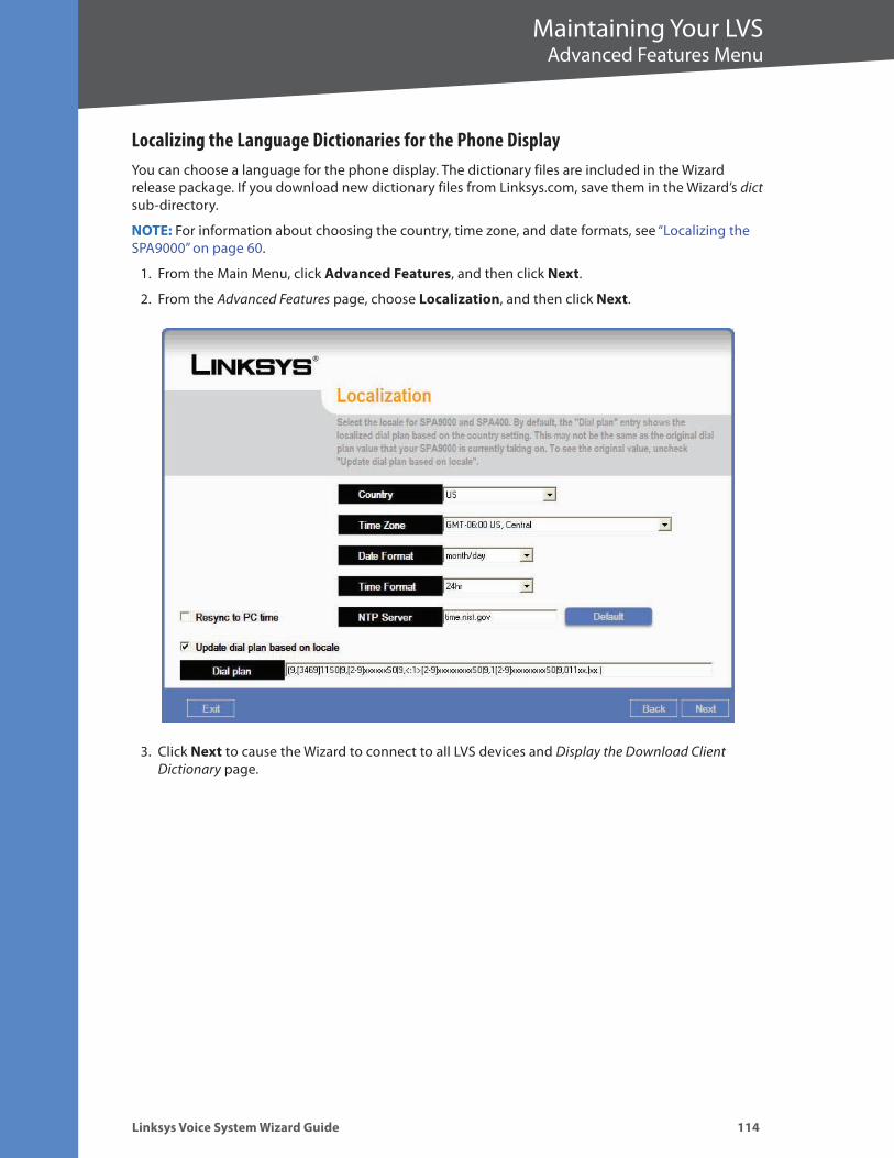
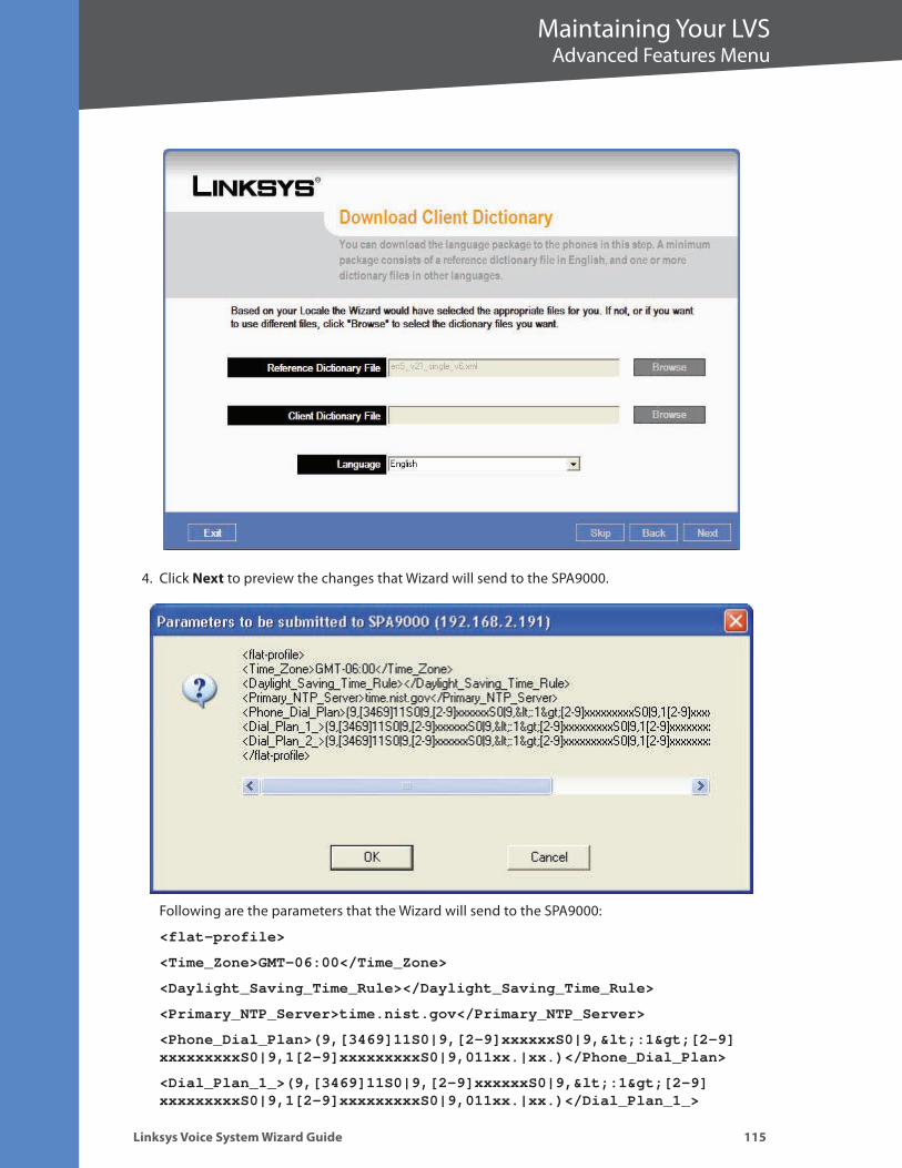
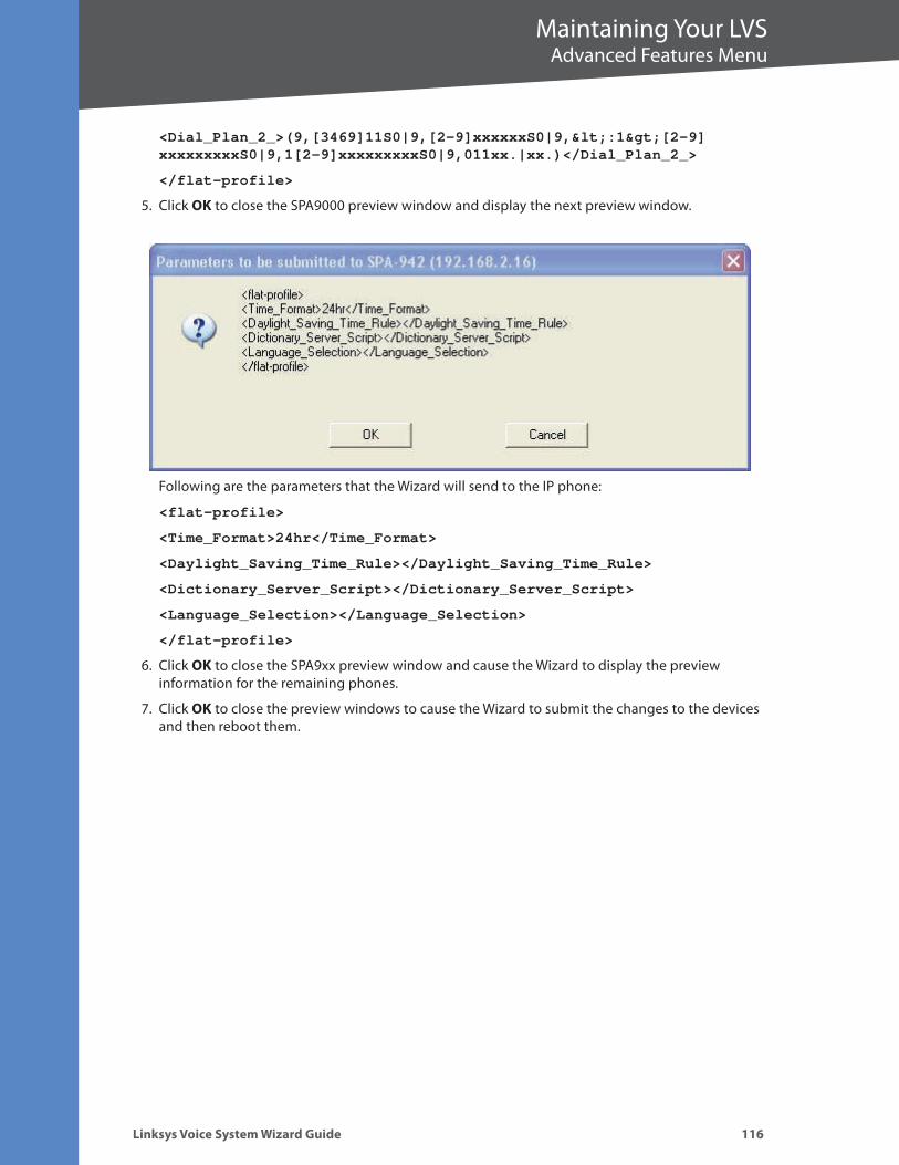
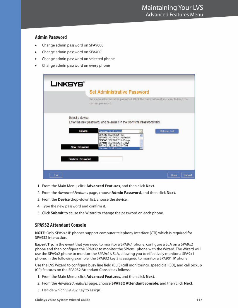
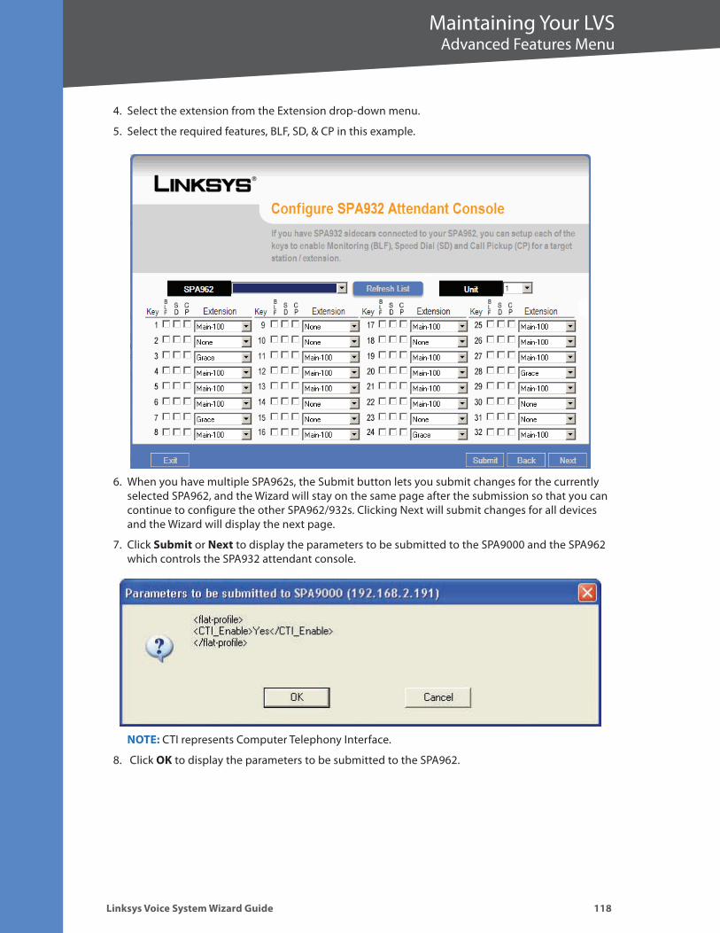
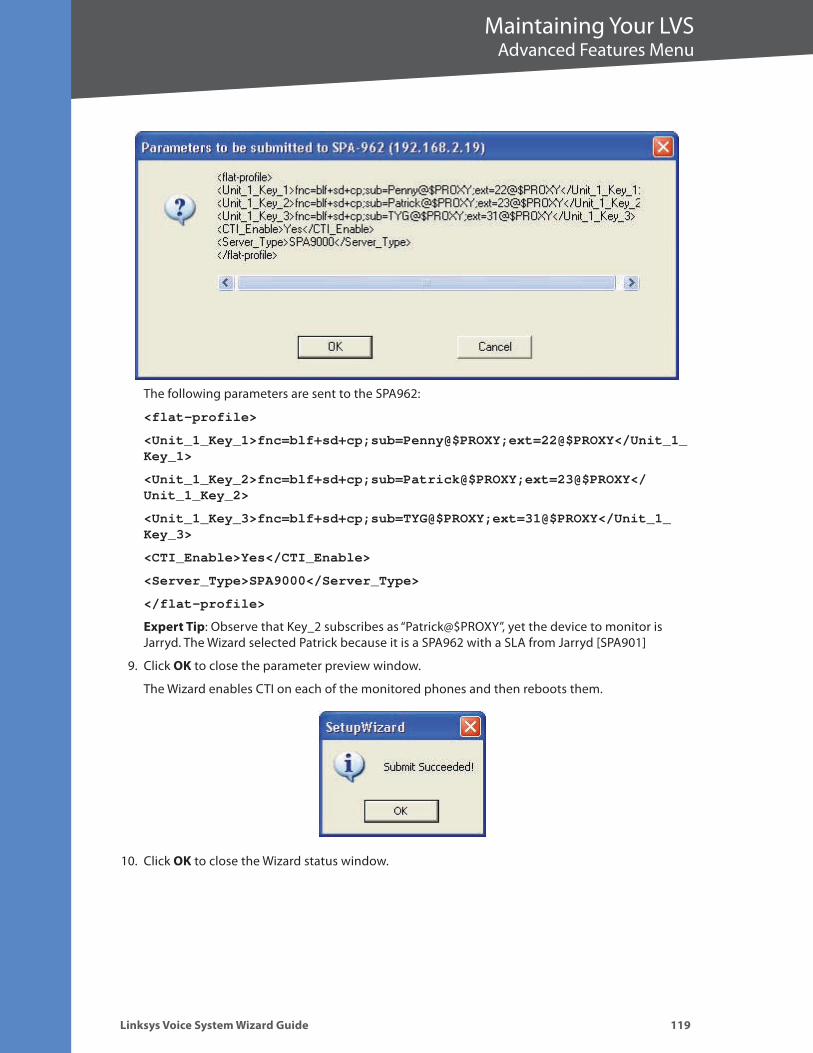
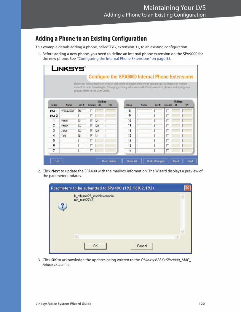
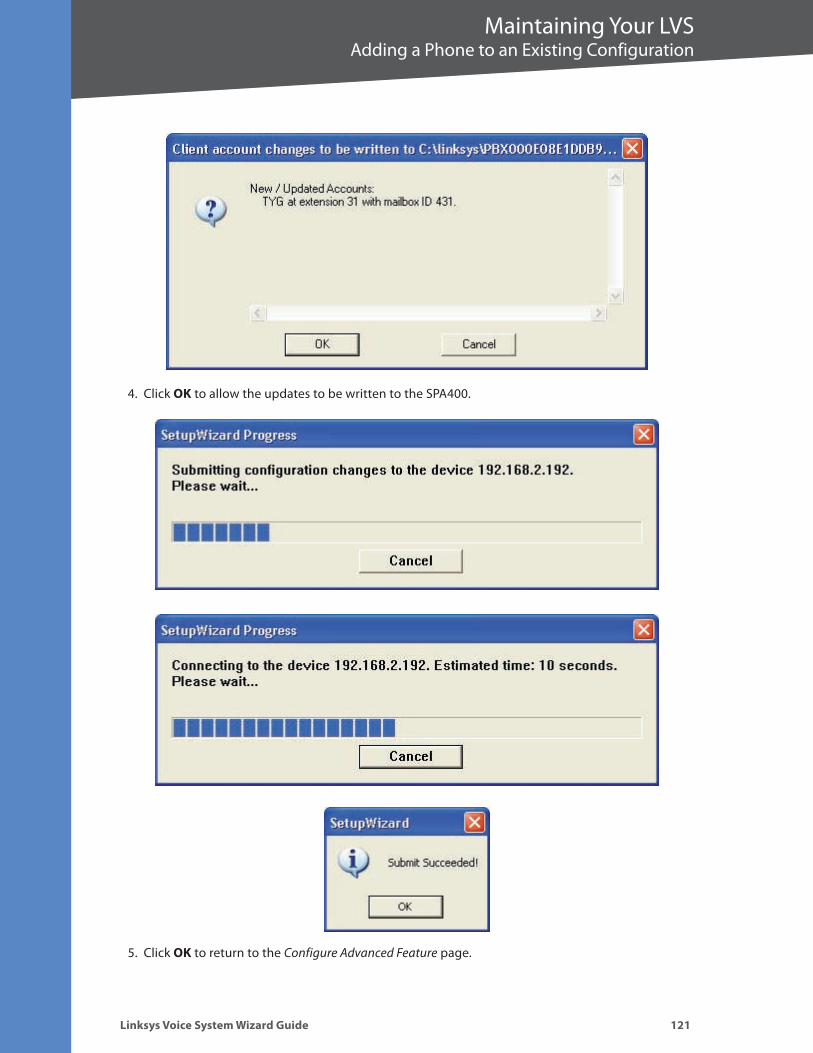
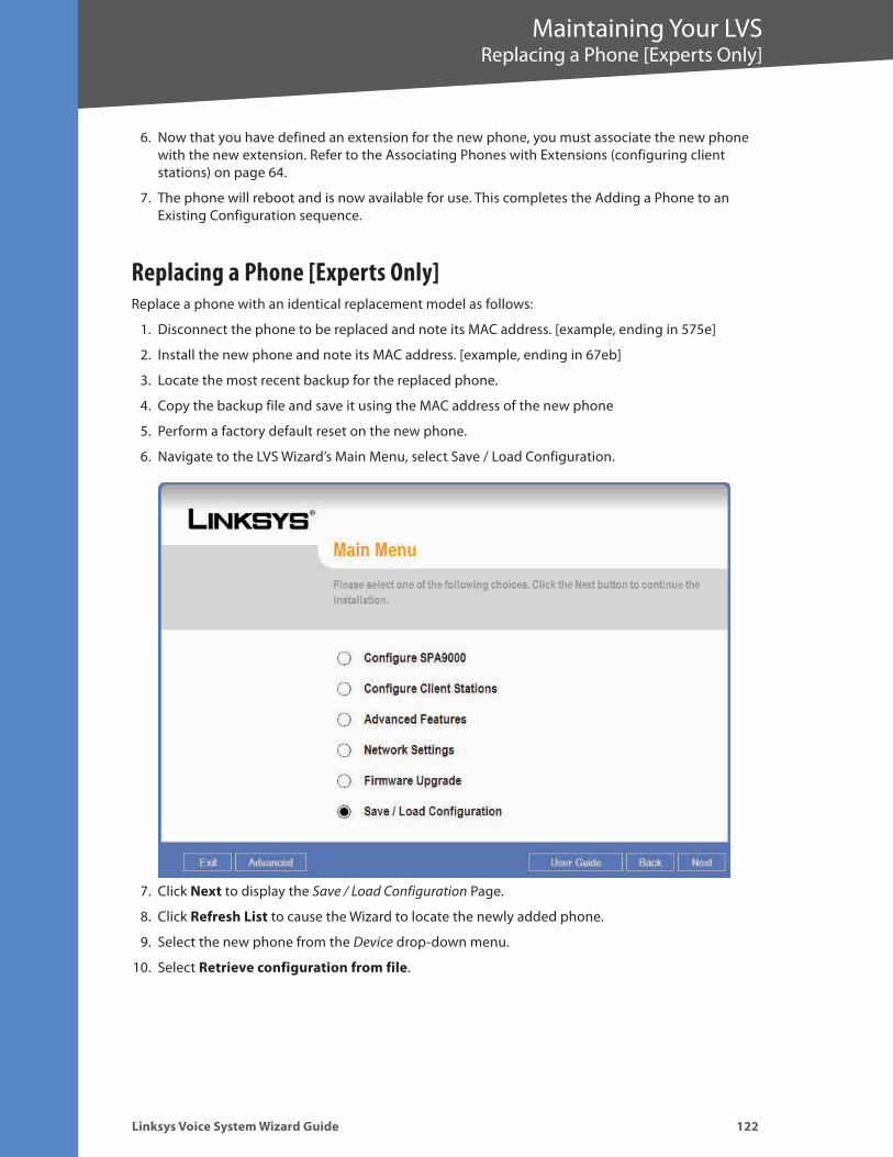
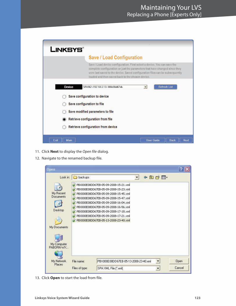
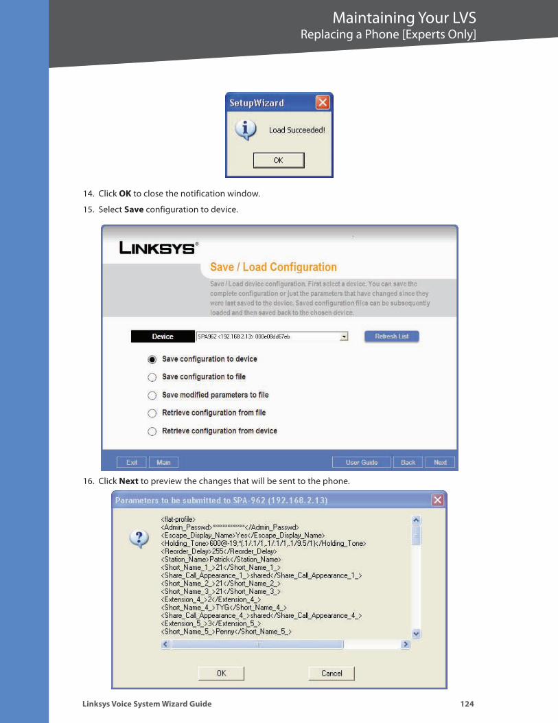
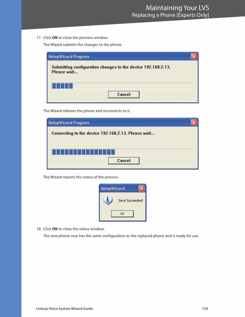
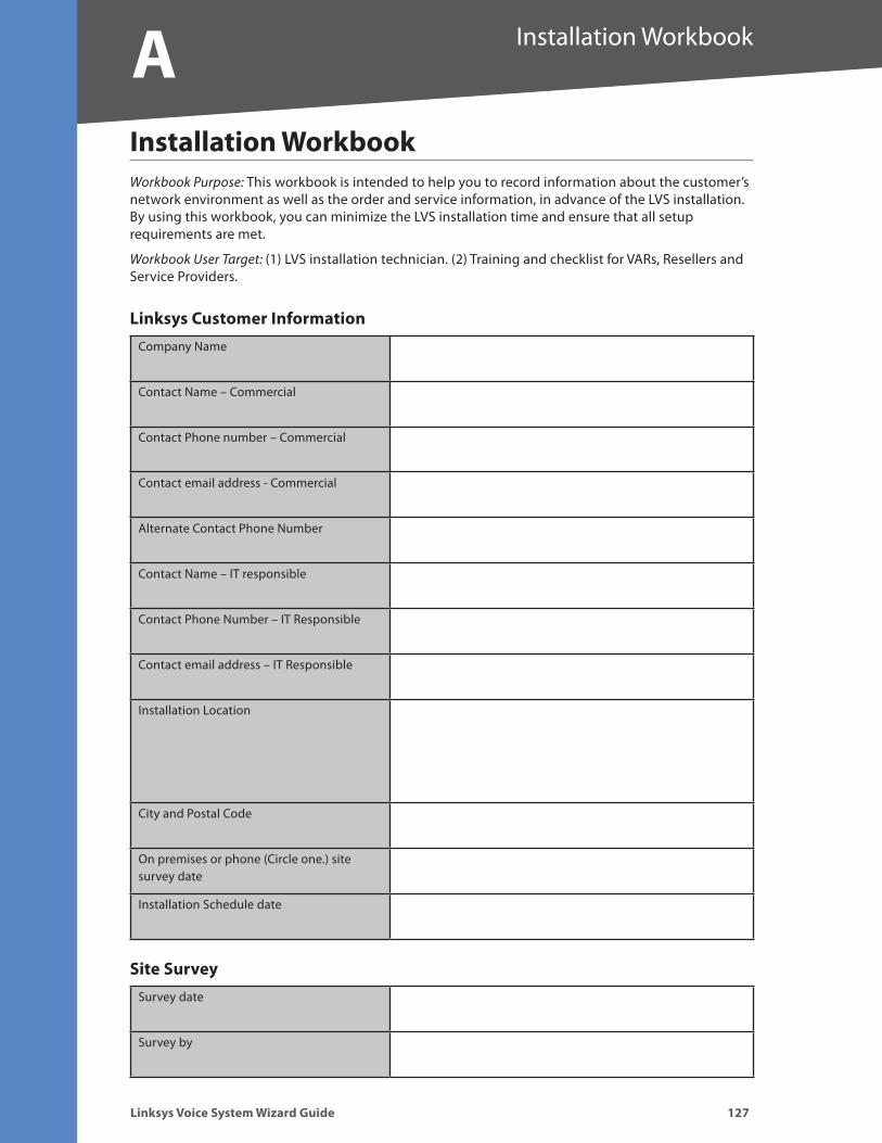
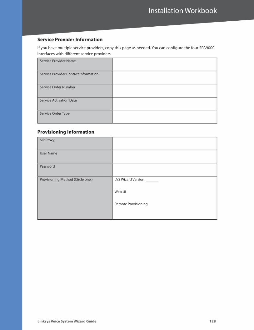
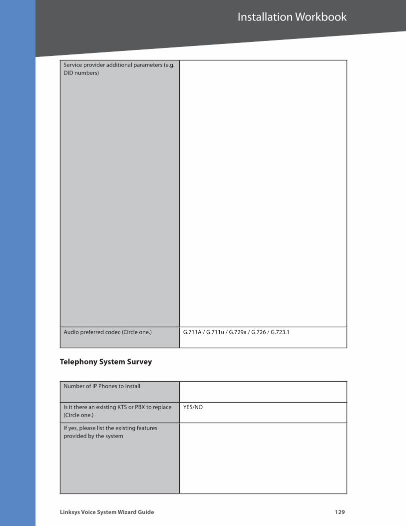
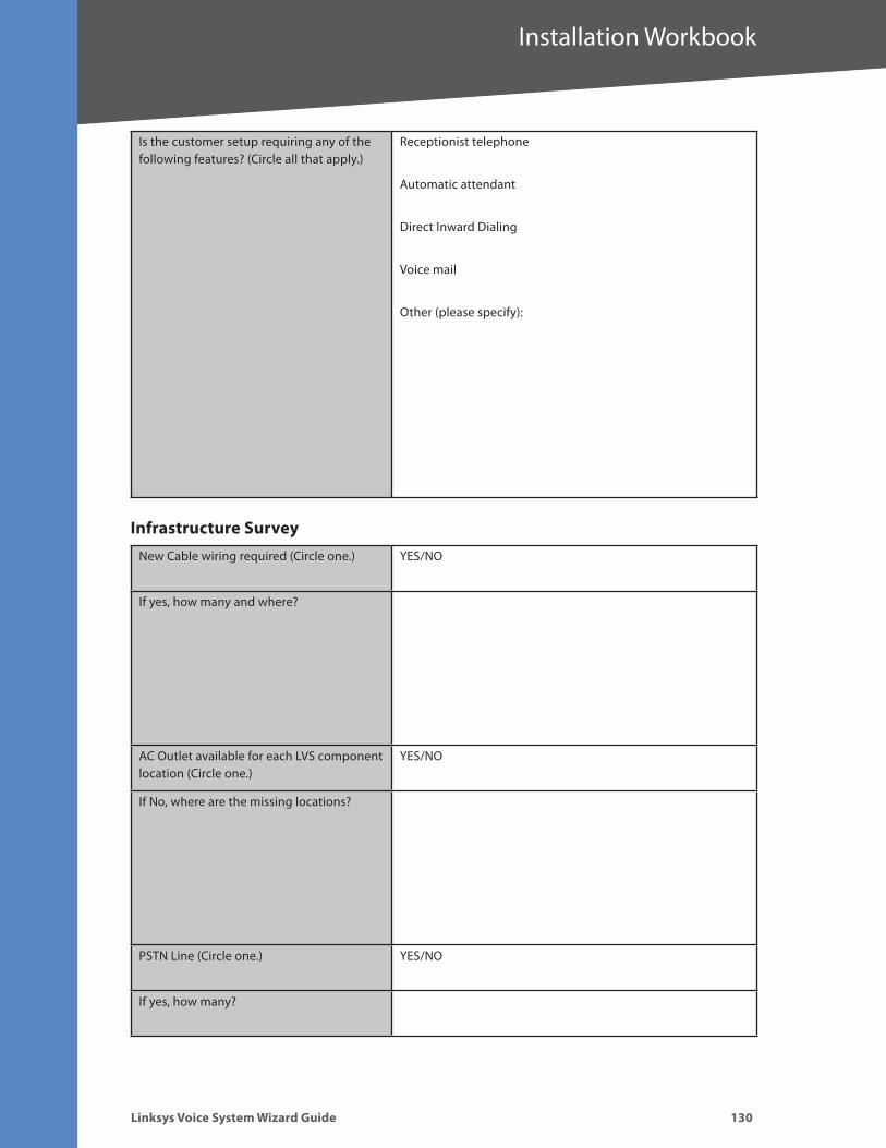
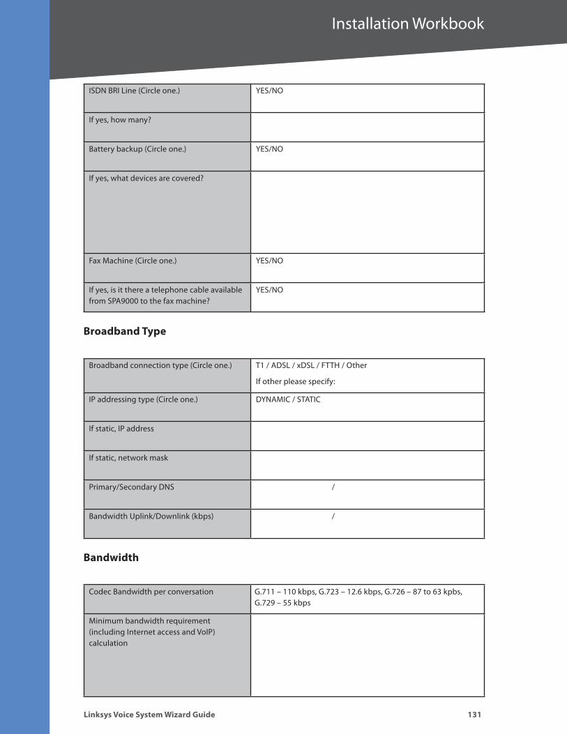
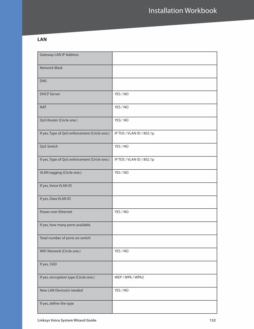
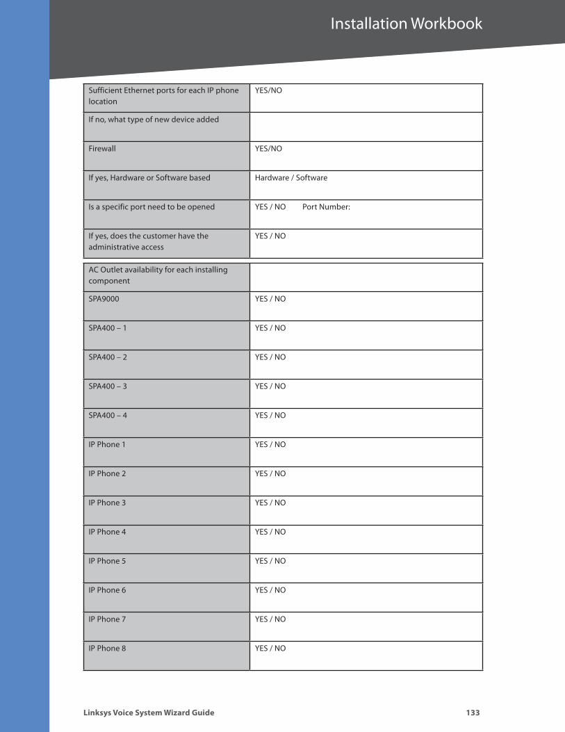
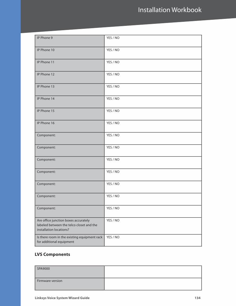
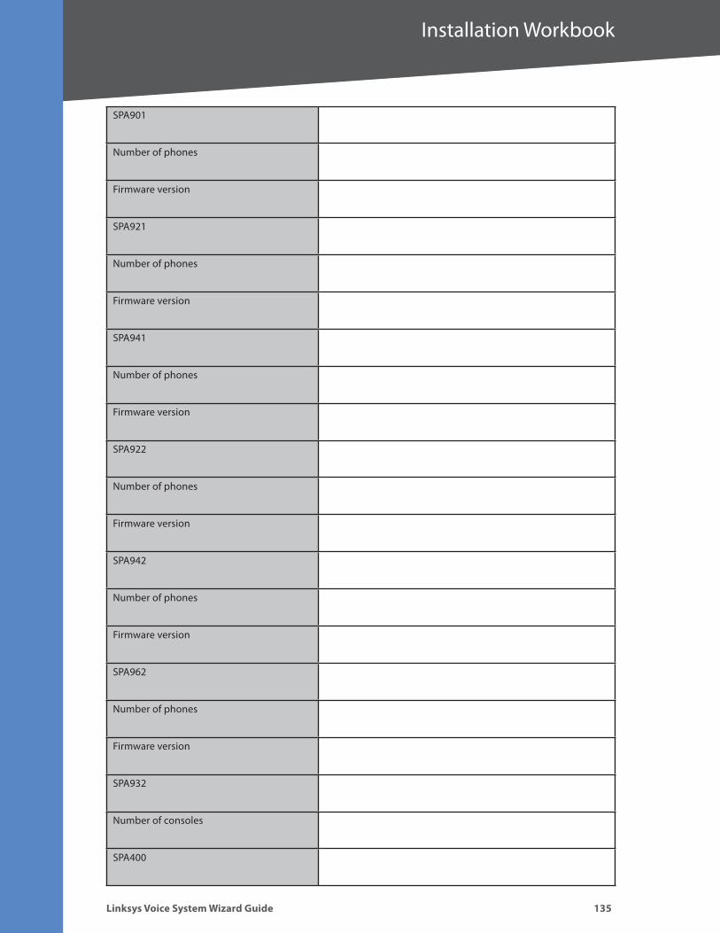
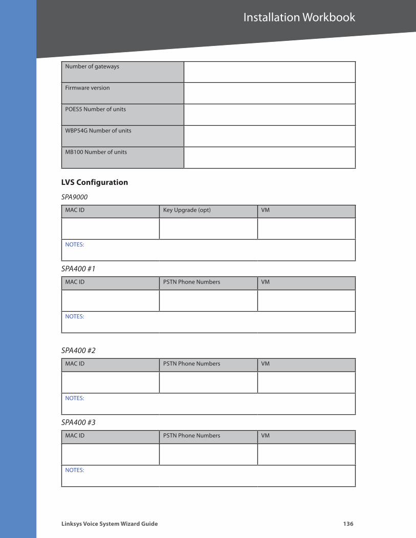
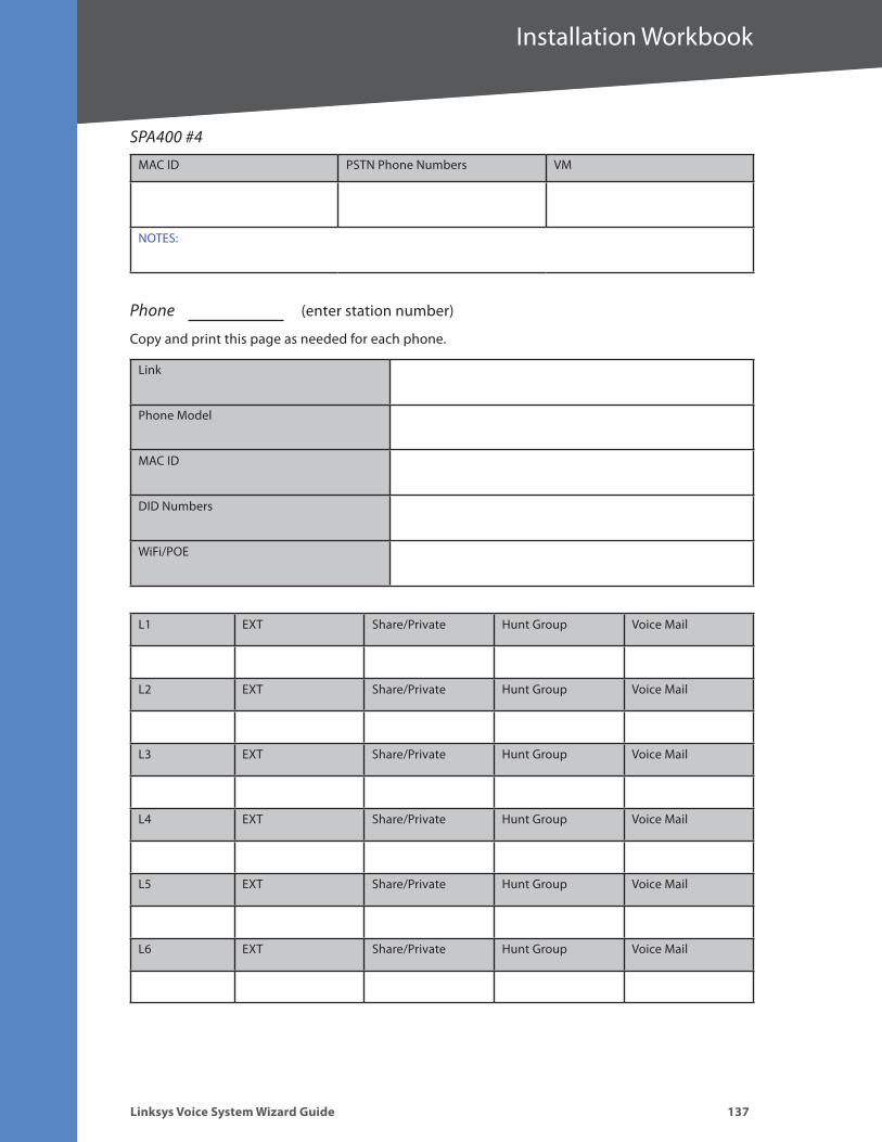
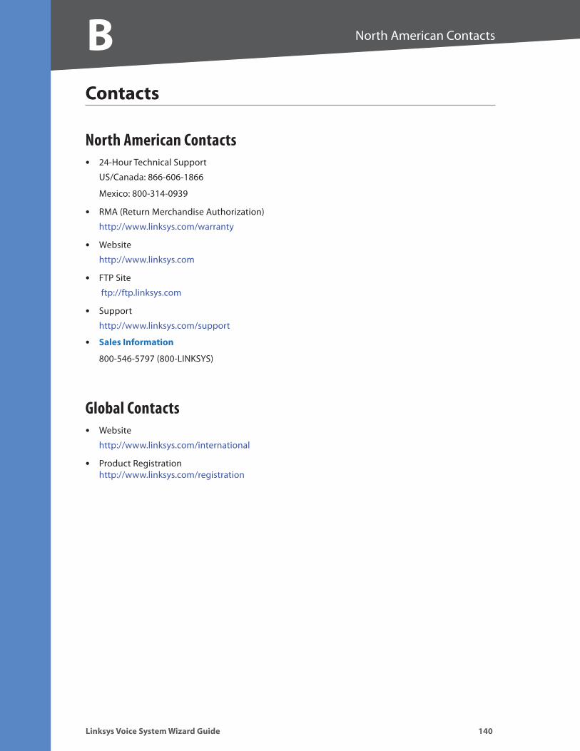


![Linksys SPA Configuration · 2017-08-18 · Linksys SPA Configuration 05/07/2010 2:43:26 PM] Router. Voice. Info System SIP Provisioning Regional Line 1 User 1 PSTN User ...](https://static.documents.pub/doc/80x56/5e625f8bf395fe104361cf7f/linksys-spa-configuration-2017-08-18-linksys-spa-configuration-05072010-24326.jpg)