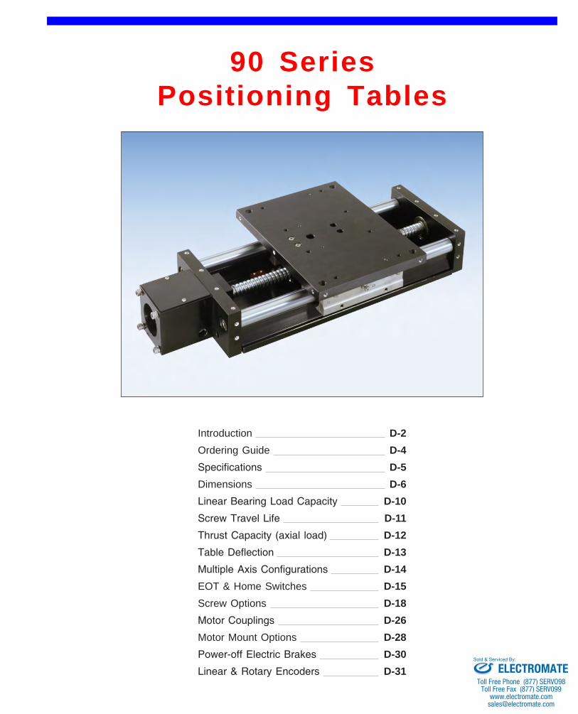
LINTECH's 90 series positioning tables offer precision performance and design flexibility for use in a wide variety of Motion Control applications.
Available Options
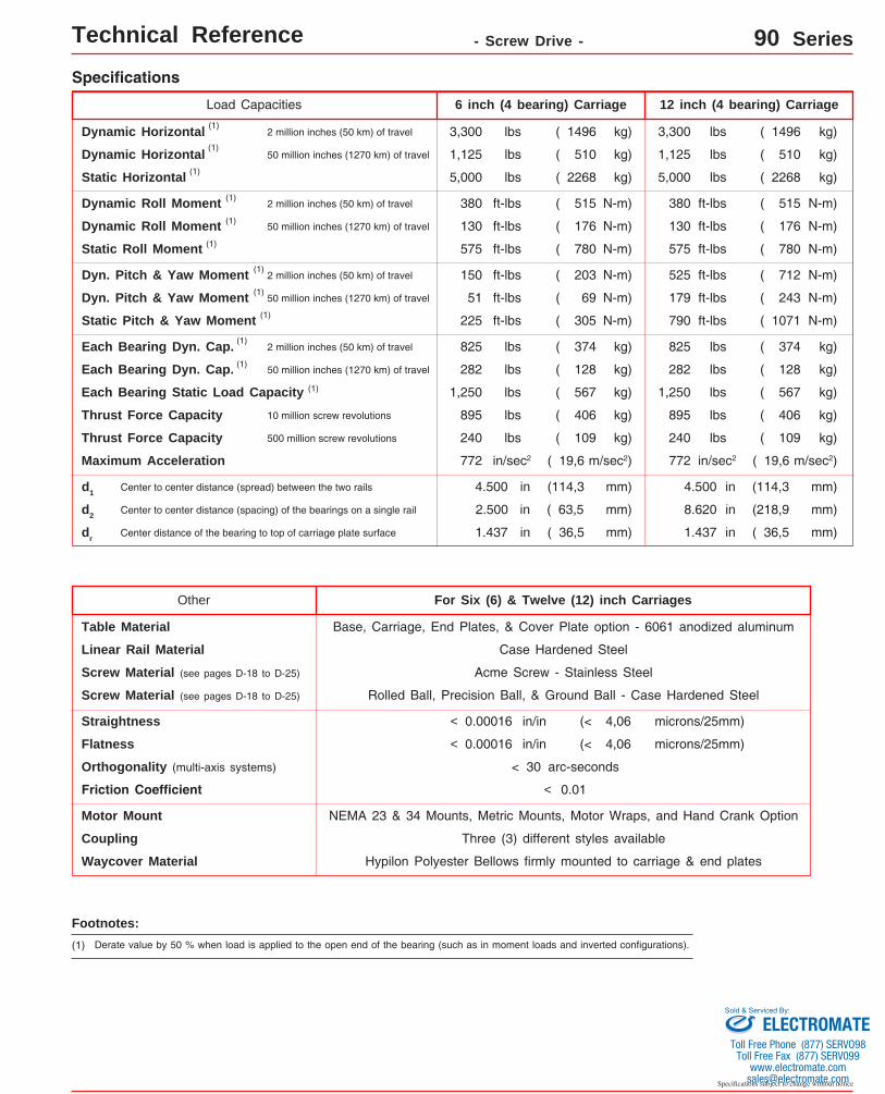
WaycoversFor operator protection, these tables can be fitted with a pro-tective bellows. The entire length of the lead screw and linear bearing system will be covered.
Specifications subject to change without notice
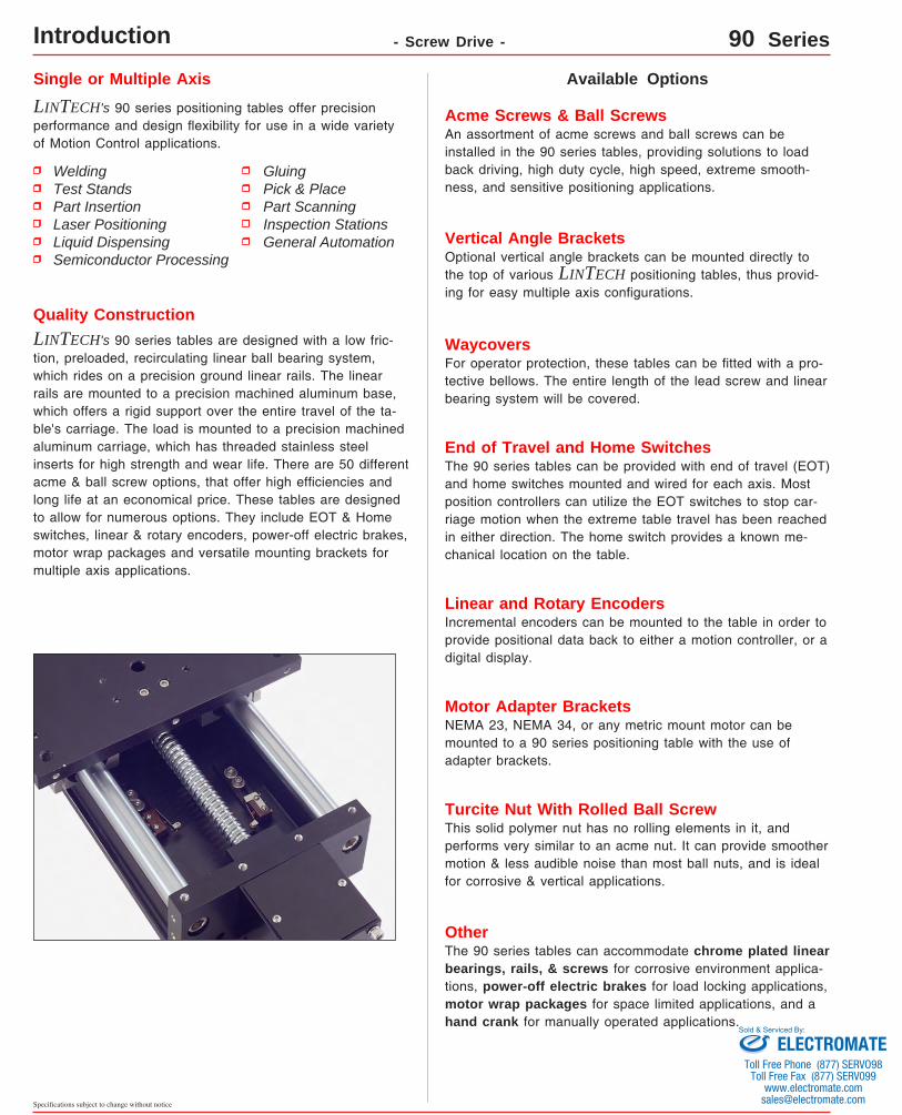
Quality ConstructionLINTECH's 90 series tables are designed with a low fric-tion, preloaded, recirculating linear ball bearing system, which rides on a precision ground linear rails. The linear rails are mounted to a precision machined aluminum base, which offers a rigid support over the entire travel of the ta-ble's carriage. The load is mounted to a precision machined aluminum carriage, which has threaded stainless steel inserts for high strength and wear life. There are 50 different acme & ball screw options, that offer high efficiencies and long life at an economical price. These tables are designed to allow for numerous options. They include EOT & Home switches, linear & rotary encoders, power-off electric brakes, motor wrap packages and versatile mounting brackets for multiple axis applications.
Welding Test Stands Part InsertionLaser PositioningLiquid Dispensing Semiconductor Processing
End of Travel and Home SwitchesThe 90 series tables can be provided with end of travel (EOT) and home switches mounted and wired for each axis. Most position controllers can utilize the EOT switches to stop car-riage motion when the extreme table travel has been reached in either direction. The home switch provides a known me-chanical location on the table.
Linear and Rotary EncodersIncremental encoders can be mounted to the table in order to provide positional data back to either a motion controller, or a digital display.
Acme Screws & Ball ScrewsAn assortment of acme screws and ball screws can be installed in the 90 series tables, providing solutions to load back driving, high duty cycle, high speed, extreme smooth-ness, and sensitive positioning applications.
OtherThe 90 series tables can accommodate chrome plated linear bearings, rails, & screws for corrosive environment applica-tions, power-off electric brakes for load locking applications, motor wrap packages for space limited applications, and a hand crank for manually operated applications.
Motor Adapter BracketsNEMA 23, NEMA 34, or any metric mount motor can be mounted to a 90 series positioning table with the use of adapter brackets.
Vertical Angle BracketsOptional vertical angle brackets can be mounted directly to the top of various LINTECH positioning tables, thus provid-ing for easy multiple axis configurations.
Turcite Nut With Rolled Ball ScrewThis solid polymer nut has no rolling elements in it, and performs very similar to an acme nut. It can provide smoother motion & less audible noise than most ball nuts, and is ideal for corrosive & vertical applications.
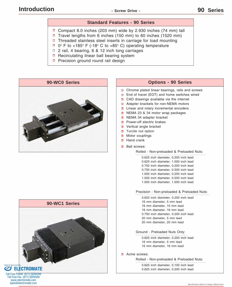
Compact 8.0 inches (203 mm) wide by 2.930 inches (74 mm) tallTravel lengths from 6 inches (150 mm) to 60 inches (1520 mm)Threaded stainless steel inserts in carriage for load mounting0o F to +185o F (-18o C to +85o C) operating temperature2 rail, 4 bearing, 6 & 12 inch long carriagesRecirculating linear ball bearing systemPrecision ground round rail design
Chrome plated linear bearings, rails and screwsEnd of travel (EOT) and home switches wiredCAD drawings available via the internetAdapter brackets for non-NEMA motorsLinear and rotary incremental encodersNEMA 23 & 34 motor wrap packagesNEMA 34 adapter bracketPower-off electric brakesVertical angle bracketTurcite nut optionMotor couplingsHand crank
0.625 inch diameter, 0.200 inch lead0.625 inch diameter, 1.000 inch lead0.750 inch diameter, 0.200 inch lead0.750 inch diameter, 0.500 inch lead1.000 inch diameter, 0.250 inch lead1.000 inch diameter, 0.500 inch lead1.000 inch diameter, 1.000 inch lead
Precision - Non-preloaded & Preloaded Nuts:
0.625 inch diameter, 0.200 inch lead16 mm diameter, 5 mm lead16 mm diameter, 10 mm lead16 mm diameter, 16 mm lead0.750 inch diameter, 0.200 inch lead20 mm diameter, 5 mm lead20 mm diameter, 20 mm lead
Ground - Preloaded Nuts Only:
0.625 inch diameter, 0.200 inch lead16 mm diameter, 5 mm lead16 mm diameter, 16 mm lead
06 = Carriage length is 06 inch (152,4 mm) with 4 bearings; Carriage weight = 5.25 lbs. (2,38 kg)
12 = Carriage length is 12 inch (304,8 mm) with 4 bearings; Carriage weight = 8.00 lbs. (3,63 kg)
16.8(7,6)90612-WC0 8
6(150)
12(300)
20.0(9,1)90618-WC0 10
18(455)
31.0(14,1)90624-WC0 14
24(605)
36.0(16,3)90630-WC0 16
30(760)
41.0(18,6)90636-WC0 18
36(910)
51.0(23,1)90648-WC0 24
48(1215)
61.0(27,7)90660-WC0 28
60(1520)
21.3(9,7)91206-WC0 8
6(150)
23.5(10,7)91212-WC0 10
12(300)
58.0(26,3)91248-WC0 28
48(1215)
68.0(30,8)91260-WC0 30
60(1520)
E
33.0(15,0)91218-WC0 14
18(455)
38.0(17,2)91224-WC0 16
24(605)
91230-WC0 1830
(760)
48.0(21,8)91236-WC0 24
36(910)
43.0(19,5)
B
15.75(400,0)
19.25(488,9)
21.75(552,4)
25.25(641,3)
27.75(704,8)
31.25(793,7)
33.75(857,2)
37.25(946,1)
39.75(1009,6)
43.25(1098,5)
45.75(1162,0)
55.25(1403,3)
57.75(1466,8)
67.25(1708,1)
69.75(1771,6)
19.25(488,9)
21.75(552,4)
25.25(641,3)
27.75(704,8)
31.25(793,7)
33.75(857,2)
37.25(946,1)
39.75(1009,6)
43.25(1098,5)
45.75(1162,0)
49.25(1250,9)
51.75(1466,8)
61.25(1555,7)
63.75(1619,2)
73.25(1860,5)
75.75(1924,0)
inches(mm)
14.94(379,4)
ScrewLength
20.94(531,9)
26.94(684,3)
32.94(836,7)
38.94(989,1)
44.94(1141,5)
56.94(1446,3)
68.94(1751,1)
62.94(1598,7)
74.94(1903,5)
50.94(1293,9)
20.94(531,9)
26.94(684,3)
32.94(836,7)
38.94(989,1)
44.94(1141,5)
C
10.00(254,0)
16.00(406,4)
22.00(558,8)
28.00(711,2)
34.00(863,6)
40.00(1016,0)
52.00(1320,8)
64.00(1625,6)
16.00(406,4)
22.00(558,8)
28.00(711,2)
34.00(863,6)
40.00(1016,0)
46.00(1168,4)
58.00(1473,2)
70.00(1778,0)
See Detail 3
See Detail 4
See Detail 5
See Detail 7
See Detail 9
See Detail 3
See Detail 4
See Detail 5
See Detail 6
See Detail 8
See Detail 10
Dimensions & Specifications - Without Waycovers -(1)
Footnotes: (1) Weight shown is with a 0.625 inch (16 mm) diameter screw, a NEMA 23 motor mount [0.34 lbs (0,16 kg)], and a C100 style [0.09 lbs (0,04 kg)] coupling.
When using a 0.750 inch (20 mm) diameter screw add 0.042 lbs per inch (0,00075 kg per mm) of screw length for a given model number. When using a 1.000 inch diameter screw add 0.117 lbs per inch (0,0021 kg per mm) of screw length for a given model number.
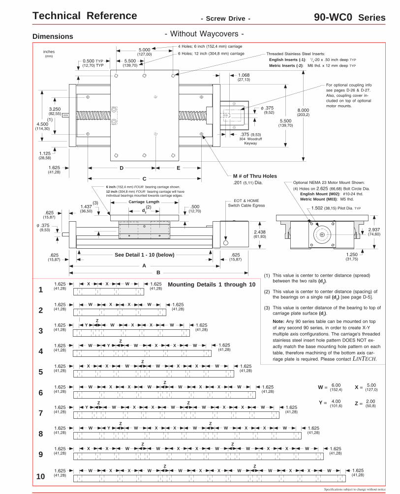
6 inch (152,4 mm) FOUR bearing carriage shown. 12 inch (304,8 mm) FOUR bearing carriage will have individual bearings mounted towards carriage edges.
(3)
Threaded Stainless Steel Inserts: English Inserts (-1): 1/4-20 x .50 inch deep TYP
Metric Inserts (-2): M6 thd. x 12 mm deep TYP
5.000(127,00)
EOT & HOME Switch Cable Egress 1.502 (38,15) Pilot Dia. TYP
5.500(139,70)
3.250(82,55)
4.500(114,30)
5.500(139,70)
.625(15,87)
2.937(74,60)
.500(12,70)
(4) Holes on 2.625 (66,68) Bolt Circle Dia. English Mount (M02): #10-24 thd. Metric Mount (M03): M5 thd.
inches(mm)
.375(9,53)
0.500 TYP(12,70) TYP
1.250(31,75)
Optional NEMA 23 Motor Mount Shown:
o
1.068(27,13)
.375(9,52)
o
.375 (9,53)304 Woodruff
Keyway
(1)
8.000(203,2)
d2
.625(15,87)
C
D E1.625(41,28)
M # of Thru Holes .201 (5,11) Dia.
Dimensions - Without Waycovers -
Mounting Details 1 through 10
See Detail 1 - 10 (below)
1.625(41,28)
W W 1.625(41,28)
X
2
4
3
5
7
9
10
1.437(36,50)
2.438(61,93)
4 Holes; 6 inch (152,4 mm) carriage
Carriage Length
6 Holes; 12 inch (304,8 mm) carriage
Technical Reference - Screw Drive - 90-WC0 Series
.625(15,87)
1.125(28,58)
For optional coupling info see pages D-26 & D-27. Also, coupling cover in-cluded on top of optional motor mounts.
X
1.625(41,28)
W 1.625(41,28)
X X WZ
W X X W W X X W
1.625(41,28)
1.625(41,28)
1.625(41,28)
W 1.625(41,28)
X X W W X X W
1.625(41,28)
W 1.625(41,28)
X X W W X X
1.625(41,28)
W 1.625(41,28)
X XW Y W
1.625(41,28)
W 1.625(41,28)
X XY
(3) This value is center distance of the bearing to top of carriage plate surface (dr).
(2) This value is center to center distance (spacing) of the bearings on a single rail (d2) [see page D-5].
(1) This value is center to center distance (spread) between the two rails (d1).
Note: Any 90 series table can be mounted on top of any second 90 series, in order to create X-Y multiple axis configurations. The carriage's threaded stainless steel insert hole pattern DOES NOT ex-actly match the base mounting hole pattern on each table, therefore machining of the bottom axis car-riage plate is required. Please contact LINTECH.
W = 6.00(152,4) X = 5.00
(127,0)
Y = 4.00(101,6) Z = 2.00
(50,8)
Z
ZZ
Z
Z
Z
1.625(41,28)
W 1.625(41,28)
X
1
Y
61.625(41,28)
W 1.625(41,28)
X X W W X XZ
81.625(41,28)
W 1.625(41,28)
X X W W X X WZZ
Y
W
W
W
X X WZ
W X X W W X X WZ
LINTECH ®
www.LintechMotion.com
Specifications subject to change without notice
D-8
ModelNumber lbs
(kg)
inches(mm)
D
inches(mm)
Mounting Dimensions
14.2(6,5)90604-WC1
inches(mm)
TravelLength
A
Table Dimensions
13.25(336,5)
M
6
TableWeight
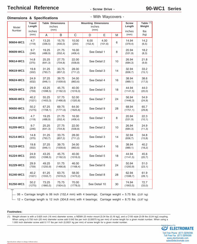
06 = Carriage length is 06 inch (152,4 mm) with 4 bearings; Carriage weight = 5.75 lbs. (2,61 kg)
12 = Carriage length is 12 inch (304,8 mm) with 4 bearings; Carriage weight = 8.75 lbs. (3,97 kg)
18.2(8,3)90609-WC1
4.7(119)
9.7(246)
21.8(9,9)90614-WC1 14.8
(375)
33.2(15,1)90619-WC1 19.8
(502)
38.6(17,5)90624-WC1 24.9
(632)
44.0(20,0)90629-WC1 29.9
(759)
54.9(24,9)90640-WC1 40.2
(1021)
65.7(29,8)90650-WC1 50.2
(1275)
22.3(10,1)91204-WC1 4.7
(119)
24.9(11,3)91209-WC1 9.7
(246)
61.9(28,1)91240-WC1 40.2
(1021)
72.7(33,0)91250-WC1 50.2
(1275)
E
34.8(15,8)91214-WC1 14.8
(375)
40.2(18,2)91219-WC1 19.8
(502)
91224-WC1 24.9(632)
51.0(23,1)91229-WC1 29.9
(759)
45.6(20,7)
B
15.75(400,0)
19.25(488,9)
21.75(552,4)
25.25(641,3)
27.75(704,8)
31.25(793,7)
33.75(857,2)
37.25(946,1)
39.75(1009,6)
43.25(1098,5)
45.75(1162,0)
55.25(1403,3)
57.75(1466,8)
67.25(1708,1)
69.75(1771,6)
19.25(488,9)
21.75(552,4)
25.25(641,3)
27.75(704,8)
31.25(793,7)
33.75(857,2)
37.25(946,1)
39.75(1009,6)
43.25(1098,5)
45.75(1162,0)
49.25(1250,9)
51.75(1466,8)
61.25(1555,7)
63.75(1619,2)
73.25(1860,5)
75.75(1924,0)
inches(mm)
ScrewLength
C
10.00(254)
16.00(406,4)
22.00(558,8)
28.00(711,2)
34.00(863,6)
40.00(1016,0)
52.00(1320,8)
64.00(1625,6)
16.00(406,4)
22.00(558,8)
28.00(711,2)
34.00(863,6)
40.00(1016,0)
46.00(1168,4)
58.00(1473,2)
70.00(1778,0)
Dimensions & Specifications - With Waycovers -(1)
Technical Reference - Screw Drive - 90-WC1 Series
Footnotes: (1) Weight shown is with a 0.625 inch (16 mm) diameter screw, a NEMA 23 motor mount [0.34 lbs (0,16 kg)], and a C100 style [0.09 lbs (0,04 kg)] coupling.
When using a 0.750 inch (20 mm) diameter screw add 0.042 lbs per inch (0,00075 kg per mm) of screw length for a given model number. When using a 1.000 inch diameter screw add 0.117 lbs per inch (0,0021 kg per mm) of screw length for a given model number.
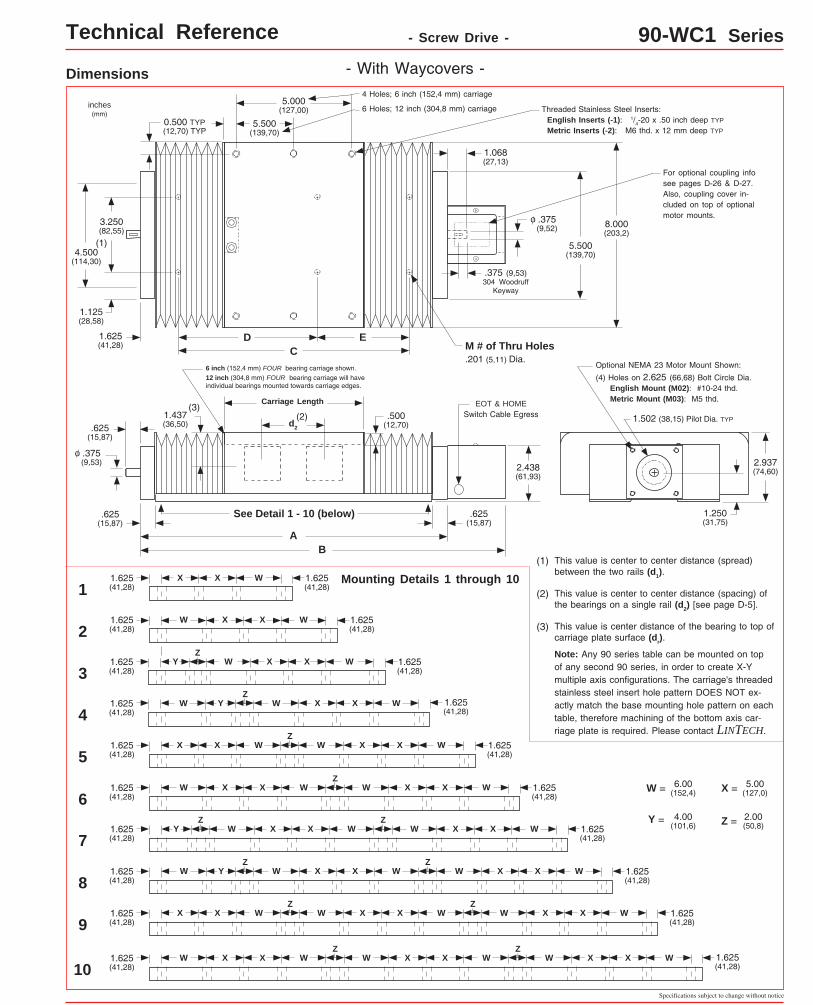
6 inch (152,4 mm) FOUR bearing carriage shown. 12 inch (304,8 mm) FOUR bearing carriage will have individual bearings mounted towards carriage edges.
(3)
Threaded Stainless Steel Inserts: English Inserts (-1): 1/4-20 x .50 inch deep TYP
Metric Inserts (-2): M6 thd. x 12 mm deep TYP
5.000(127,00)
EOT & HOME Switch Cable Egress 1.502 (38,15) Pilot Dia. TYP
5.500(139,70)
3.250(82,55)
4.500(114,30)
5.500(139,70)
2.937(74,60)
.500(12,70)
(4) Holes on 2.625 (66,68) Bolt Circle Dia. English Mount (M02): #10-24 thd. Metric Mount (M03): M5 thd.
inches(mm)
.375(9,53)
0.500 TYP(12,70) TYP
1.250(31,75)
Optional NEMA 23 Motor Mount Shown:
o
1.068(27,13)
.375(9,52)
o
.375 (9,53)304 Woodruff
Keyway
(1)
8.000(203,2)
d2
CD E1.625
(41,28) M # of Thru Holes .201 (5,11) Dia.
Dimensions - With Waycovers -
1.437(36,50)
2.438(61,93)
4 Holes; 6 inch (152,4 mm) carriage
Carriage Length
6 Holes; 12 inch (304,8 mm) carriage
.625(15,87)
1.125(28,58)
For optional coupling info see pages D-26 & D-27. Also, coupling cover in-cluded on top of optional motor mounts.
AB
.625(15,87)
.625(15,87)
See Detail 1 - 10 (below)
X Mounting Details 1 through 10
1.625(41,28)
W W 1.625(41,28)
X
2
4
3
5
7
9
10
X
1.625(41,28)
W 1.625(41,28)
X X WZ
W X X W W X X W
1.625(41,28)
1.625(41,28)
1.625(41,28)
W 1.625(41,28)
X X W W X X W
1.625(41,28)
W 1.625(41,28)
X X W W X X
1.625(41,28)
W 1.625(41,28)
X XW Y W
1.625(41,28)
W 1.625(41,28)
X XY
(3) This value is center distance of the bearing to top of carriage plate surface (dr).
(2) This value is center to center distance (spacing) of the bearings on a single rail (d2) [see page D-5].
(1) This value is center to center distance (spread) between the two rails (d1).
Note: Any 90 series table can be mounted on top of any second 90 series, in order to create X-Y multiple axis configurations. The carriage's threaded stainless steel insert hole pattern DOES NOT ex-actly match the base mounting hole pattern on each table, therefore machining of the bottom axis car-riage plate is required. Please contact LINTECH.
W = 6.00(152,4) X = 5.00
(127,0)
Y = 4.00(101,6) Z = 2.00
(50,8)
Z
ZZ
Z
Z
Z
1.625(41,28)
W 1.625(41,28)
X
1
Y
61.625(41,28)
W 1.625(41,28)
X X W W X XZ
81.625(41,28)
W 1.625(41,28)
X X W W X X WZZ
Y
W
W
W
X X WZ
W X X W W X X WZ
LINTECH ®
www.LintechMotion.com
Specifications subject to change without notice
Linear Bearing Load Capacities
Travel Life millions of inches (Km)
1,000
100
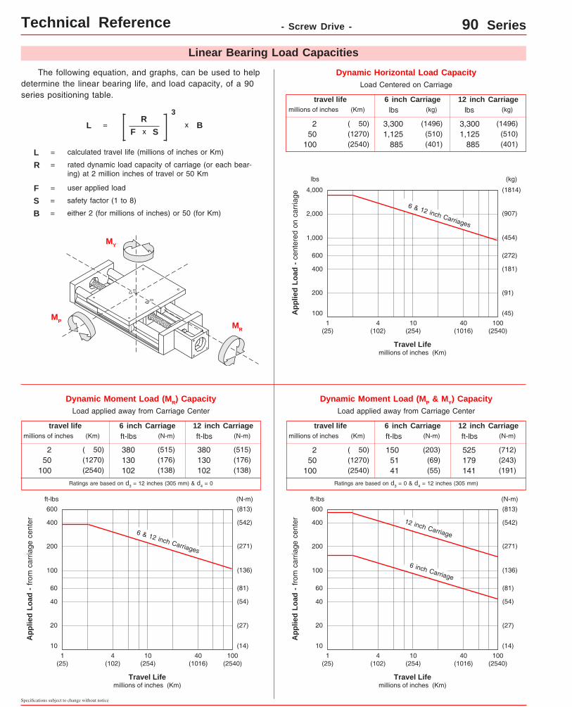
Dynamic Horizontal Load CapacityLoad Centered on Carriage
App
lied
Load
- c
ente
red
on c
arria
ge
1(25)
400
4,000
(45)
(181)
(454)
(1814)
10(254)
100(2540)
40(1016)
4(102)
lbs (kg)
600
200
2,000
Dynamic Moment Load (MP & MY) CapacityLoad applied away from Carriage Center
6 & 12 inch Carriages
(907)
(91)
(272)
Travel Life millions of inches (Km)
100
10
Dynamic Moment Load (MR) CapacityLoad applied away from Carriage Center
App
lied
Load
- fr
om c
arria
ge c
ente
r
1(25)
40
400
10(254)
100(2540)
40(1016)
4(102)
ft-lbs
60
20
200
(14)
(54)
(136)
(542)
(N-m)
(271)
(27)
(81)
6 & 12 inch Carriages
D-10
12 inch Carriage6 inch Carriagelbs(Km)millions of inches
travel life
250
100
(kg)lbs
3,3001,125
885
(1496)(510)(401)
(kg)
( 50)(1270)(2540)
3,3001,125
885
(1496)(510)(401)
12 inch Carriage6 inch Carriageft-lbs(Km)millions of inches
travel life
250
100
(N-m)ft-lbs (N-m)
( 50)(1270)(2540)
1505141
(203)(69)(55)
525179141
(712)(243)(191)
12 inch Carriage6 inch Carriageft-lbs(Km)millions of inches
travel life
250
100
(N-m)ft-lbs (N-m)
( 50)(1270)(2540)
380130102
(515)(176)(138)
380130102
(515)(176)(138)
(813)600
Travel Life millions of inches (Km)
100
10
App
lied
Load
- fr
om c
arria
ge c
ente
r
1(25)
40
400
10(254)
100(2540)
40(1016)
4(102)
ft-lbs
60
20
200
(14)
(54)
(136)
(542)
(N-m)
(271)
(27)
(81)
6 inch Carriage
(813)600
12 inch Carriage
Ratings are based on d3 = 12 inches (305 mm) & d4 = 0 Ratings are based on d3 = 0 & d4 = 12 inches (305 mm)
Technical Reference - Screw Drive - 90 Series
The following equation, and graphs, can be used to help determine the linear bearing life, and load capacity, of a 90 series positioning table.
L =R
F
3
x B
L = calculated travel life (millions of inches or Km)
R = rated dynamic load capacity of carriage (or each bear-ing) at 2 million inches of travel or 50 Km
F = user applied load
B = either 2 (for millions of inches) or 50 (for Km)
MR
x S
S = safety factor (1 to 8)
MP
MY
LINTECH ®
www.LintechMotion.com
Specifications subject to change without notice
D-11
Technical Reference - Screw Drive - 90 Series
Screw Travel Life
60
40
100
80
400
200
600
800
1000
2000
4000
27
18
45
36
181
91
272
363
454
907
1814
LbsKg
Rat
ed l
oad
- as
see
n by
scr
ew n
ut
Travel Life
209
Millions of Inches(Km)
1(25,4)
2(50,8)
4(102)
6(152)
10(254)
20(508)
40(1016)
60(1524)
100(2540)
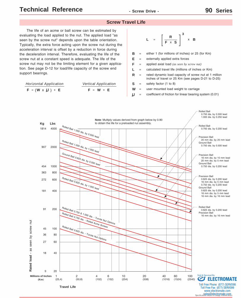
Rolled Ball 0.625 dia. - Turcite Nut Options
Rolled Ball 0.750 dia. - Rolled Acme Screws
Ground Ball 0.625 dia. by 0.500 lead
Rolled Ball 0.625 dia. by 1.000 lead
Rolled Ball 0.625 dia. by 0.200 leadPrecision Ball 16 mm dia. by 16 mm lead
Precision Ball 0.625 dia. by 0.200 lead 16 mm dia. by 5 mm lead 0.750 dia. by 0.200 leadGround Ball 0.625 dia. by 0.200 lead 16 mm dia. by 5 mm lead 16 mm dia. by 16 mm lead
Precision Ball 16 mm dia. by 10 mm lead 20 mm dia. by 5 mm leadGround Ball 0.750 dia. by 0.200 lead
Precision Ball 20 mm dia. by 20 mm leadGround Ball 0.750 dia. by 0.500 lead
Rolled Ball 0.750 dia. by 0.200 lead
Rolled Ball 1.000 dia. by 1.000 lead
Rolled Ball 0.750 dia. by 0.500 lead 1.000 dia. by 0.250 lead
The life of an acme or ball screw can be estimated by evaluating the load applied to the nut. The applied load "as seen by the screw nut" depends upon the table orientation. Typically, the extra force acting upon the screw nut during the acceleration interval is offset by a reduction in force during the deceleration interval. Therefore, evaluating the life of the screw nut at a constant speed is adequate. The life of the screw nut may not be the limiting element for a given applica-tion. See page D-12 for load/life capacity of the screw end support bearings.
Vertical Application
coefficient of friction for linear bearing system (0.01)
Horizontal Application
L = calculated travel life (millions of inches or Km)
R = rated dynamic load capacity of screw nut at 1 million inches of travel or 25 Km (see pages D-21 to D-25)
F =
B = either 1 (for millions of inches) or 25 (for Km)
L =R
F
3
x Bx S
S = safety factor (1 to 8)
=F xW W
applied axial load (as seen by screw nut)
= user mounted load weight to carriage=F W=
externally applied extra forces
( ) + E + E
E =
Note: Multiply values derived from graph below by 0.90 to obtain the life for a preloaded nut assembly.
Number of Screw Revolutionsmillions of screw revolutions
Static 1 2 10 50 100 500
1,725(782)
1,725(782)
1,530(694)
895(406)
525(238)
415(188)
240(109)
lbs(kg)
ThrustCapacity
Screw End Supports
90 Series
Specifications subject to change without notice
D-12
Technical Reference
Note: Multiply screw revolutions by the screw lead in order to convert to inches (or mm) traveled by the nut.
The life of the screw end support bearings can be estimated by evaluating the applied axial (thrust) load. The ap-plied load "as seen by the bearings" depends upon the table orientation. Typically, the extra force acting upon the bear-ings during the acceleration interval is offset by a reduction in force during the deceleration interval. Therefore, evaluating the life of the bearings at a constant speed is adequate. The life of the screw end support bearings may not be the limiting element for a given application. See page D-11 for load/life capacity of acme and ball screw nuts.
Vertical Application
coefficient of friction for linear bearing system (0.01)
Horizontal Application
L = calculated life (millions of revolutions)
R = dynamic load capacity of bearings at 2 million screw revolutions (see below)
The "moment of inertia" of an object is a gauge of the strength of that object to resist deflecting when used in an applica-tion or orientation where deflection might occur. The higher an I value relates to a lower amount of deflection.
W W
I = 0.28 in4 (1.16 x 105 mm4) I = 4.81 in4 (20.00 x 105 mm4)
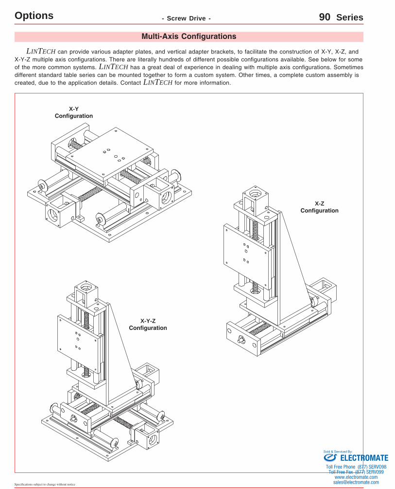
LINTECH can provide various adapter plates, and vertical adapter brackets, to facilitate the construction of X-Y, X-Z, and X-Y-Z multiple axis configurations. There are literally hundreds of different possible configurations available. See below for some of the more common systems. LINTECH has a great deal of experience in dealing with multiple axis configurations. Sometimes different standard table series can be mounted together to form a custom system. Other times, a complete custom assembly is created, due to the application details. Contact LINTECH for more information.
LINTECH provides several options for EOT & home switches. One style uses mechanically actuated switches, while other styles use "non-contact" versions. When ordered with a LINTECH 90 series table, each switch is mounted to the base of the table, while the actuating cams are mounted to the carriage assembly. Each switch is mounted to a plate that allows for a 0.625 inch (16 mm) adjustment range. The switches are pre-wired by LINTECH for easy interfacing to the users Motion Controller.
End of Travel (EOT) SwitchesEnd of travel (EOT) switches can be utilized by a motion controller to stop carriage motion, thereby preventing any damage to personnel, table carriage, or user mounted load if the extreme end of travel has been reached by the carriage. There are two EOT switches mounted to the side of the table, one on each end. The CCW switch is mounted at the motor mount end, while the CW switch is located at the opposite end of the table. LINTECH provides normally closed (NC) end of travel switches. This provides for a power-off fail safe system, where the position controller can detect broken wires. It is highly recommended that any positioning table used with a position controller, should have end of travel switches installed for protection of personnel, table carriage, and user mounted load.
Home SwitchThe home switch can be utilized by a motion controller as a known fixed mechanical location on the positioning table. The switch is located on the opposite side of the EOT switches, at the motor mount end, and is a normally open (NO) switch.
Switch LocationsThe following diagram shows the locations of the switches when ordered from LINTECH.
Note: The repeatability of any switch is dependent upon several factors: carriage speed, accel rate, load weight, switch style, and the position controller. LINTECH's ratings are based upon a carriage speed of 0.5 inches/sec (12.7 mm/sec) and a no load condition.
CW EOT
Home
ShieldedCable
End of Travel (EOT) Switches & Home Switch
CCW EOT
Each switch bracket has a 0.625 inch (16 mm) adjustment range
Note:
For the 90-WC0 series, EOT switches are normally located 0.375 inches (9,5 mm) inward from the maximum travel hard stops. Thus, reducing overall system travel by 0.750 inches (19,1 mm) from listed table travel for each model #. For the 90-WC1 series there is NO reduction of listed travel length when using EOT switches.
Non-Contact Proximity SwitchesNon-Contact Hall Effect Switches
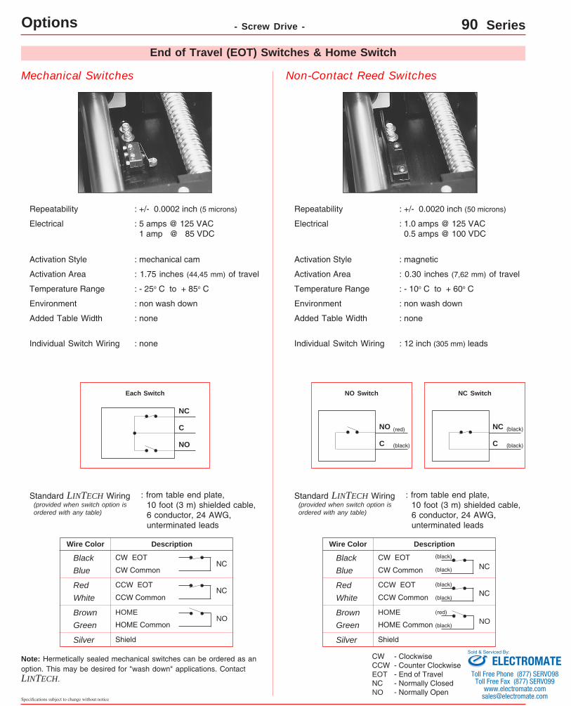
Repeatability : +/- 0.0002 inch (5 microns)
Electrical : 5 - 24 VDC 15 mA - power input 25 mA max - signal
Repeatability : +/- 0.0002 inch (5 microns)
Electrical : 10 - 28 VDC 15 mA - power input 100 mA max - signal
Actuation Style : magnetic
Activation Area : 0.32 inches (8,13 mm) of travel
Temperature Range : - 10o C to + 60o C
Added Table Width : none
Environment : wash down
Individual Switch Wiring : 12 inch (305 mm) leads
NPN wiring connection - both NC & NO
5 - 24 VDCLoad
Power - (Brown)
Signal - (Black)
Common - (Blue)
: from table end plate, 10 foot (3 m) shielded cable; 9 conductor, 24 AWG, unterminated leads
Standard LINTECH Wiring
NPN Switch
DescriptionWire Color
Brown CW Power
Black CW EOT
Blue CW Common
switch
(brown)
(black)
(blue)
NC
Red CCW Power
White CCW EOT
Green CCW Common
switch(black)
(blue)
NC
(brown)
Orange Home Power
Yellow Home
Grey Home Common
switch(black)
(blue)
NO
ShieldSilver
(brown)
Actuation Style
Activation Area : 1.75 inches (44,45 mm) of travel
Temperature Range : - 25o C to + 75o C
: non-magnetic cam
Added Table Width
Environment : IEC IP67 wash down
Individual Switch Wiring : 6.5 foot (2 m) cable for NPN
NPN wiring connection - both NC & NO
10 - 28 VDCLoad
Power - (Brown)
Signal - (Black)
Sinking Common - (Blue)
: from table end plate, 10 foot (3 m) shielded cable; 9 conductor, 24 AWG, unterminated leads
Standard LINTECH Wiring
NPN Switch
: none
DescriptionWire Color
Brown CW Power
Black CW EOT
Blue CW Common
switch
(brown)
(black)
(blue)
NC
Red CCW Power
White CCW EOT
Green CCW Common
switch(black)
(blue)
NC
(brown)
Orange Home Power
Yellow Home
Grey Home Common
switch(black)
(blue)
NO
ShieldSilver
(brown)
(provided when switch option is ordered with any table)
(provided when switch option is ordered with any table)
End of Travel (EOT) Switches & Home Switch
PNP wiring connection - both NC & NO
10 - 28 VDCLoad
Power - (Brown)
Signal - (Black)
Sourcing Common - (Blue)
PNP Switch
Sinking
: 3.3 foot (1 m) cable for PNP
LINTECH ®
www.LintechMotion.comD-18
Specifications subject to change without notice
Options - Screw Drive - 90 Series
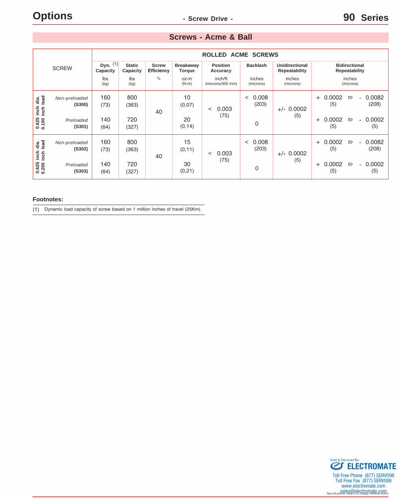
Screws - Acme & Ball
Acme screws use a turcite (polymer), or bronze nut. The nut threads ride in the matching acme screw threads, much like the ordinary nut and bolt system. This produces a higher friction (lower efficiency) system than a ball screw assembly, since there are no rolling elements between the nut and the acme screw threads. For applications requiring low speeds, noise and duty cycles, an acme screw works fine. Also, an acme screw is a good choice for most vertical applications, as it typically prevents back driving of the attached load. Ball screws are the screw of choice for high duty cycle, high speed, and long life applications. The 90 series tables can be fitted with an assortment of ball screws. The ball screw nut uses one or more circuits of recirculating steel balls which roll between the nut and ball screw grooves, providing an efficient low friction system. Using a higher lead
ball screw (for example a 0.500 inch lead instead of a 0.200 inch lead) will offer greater carriage speed for applications requiring rapid traverse, or fast, short incremental moves. Low wear and long life are key features of a ball screw sys-tem. LINTECH provides three different ball screw configura-tions. The rolled ball screw system utilizes a tapped nut with a standard accuracy grade rolled screw. The precision ball screw system utilizes a ground nut with a higher accuracy grade rolled screw. The ground ball screw system utilizes a ground nut with a high accuracy precision ground screw. Some screws are available with preloaded nuts. The preloaded nut assembly offers high bidirectional repeatabil-ity by eliminating backlash.
Consideration CommentsAcme ScrewBall Screws
GroundRolled
less audible noise thanprecisionscrew
most audible noise
least audiblenoise
Audible noise Acme: no rolling elements provide for quiet operation.Ball: recirculating balls in nut assembly transmit audible noise during motion; due to more accurate machining procedures - precision & ground ball screws are quieter than rolled ball screws.
can easily back drive a load
can easily back drive a load
may preventback driving
Back Driving Loads
Acme: good for light loads & vertical applications.Ball: recirculating balls in nut assembly produce a low friction system; vertical applications may require a brake to hold the load when no power is applied to the motor.
Screw Efficiency Acme: low efficiency due to high sliding friction.Ball: high efficiency due to recirculating balls in nut assembly - low friction system.
smoothestleast smoothcan be smooth
Smoothness Acme: due to friction can start/stop at very low speeds.Ball: smoothness is constant through a wide speed range; due to more accurate manufacturing procedures precision rolled & ground ball screws are smoother than rolled ball screws.
highhighlowSpeeds Acme: high friction can causes excess heat & wear at high speeds.Ball: recirculating balls in nut provide for a high speed system due to low friction & high efficiency.
high (100 %)
high (100 %)
low to medium(< 50 %)
Duty Cycle Acme: low duty cycle due to high sliding friction.Ball: high duty cycle due to recirculating balls in nut assembly;high efficiency & low friction system.
Life Acme: mechanical wear related to duty cycle, load & speed.Ball: minimal wear if operated in proper environment, within load specifications, and periodically lubricated.
shorter due to higher friction
long long
most expensive
least expensive
slightly more than rolledball
Relative - Cost Acme: a little more expensive than the rolled ball screw.Ball: due to more accurate manufacturing procedures precision rolled & ground ball screws are more expensive.
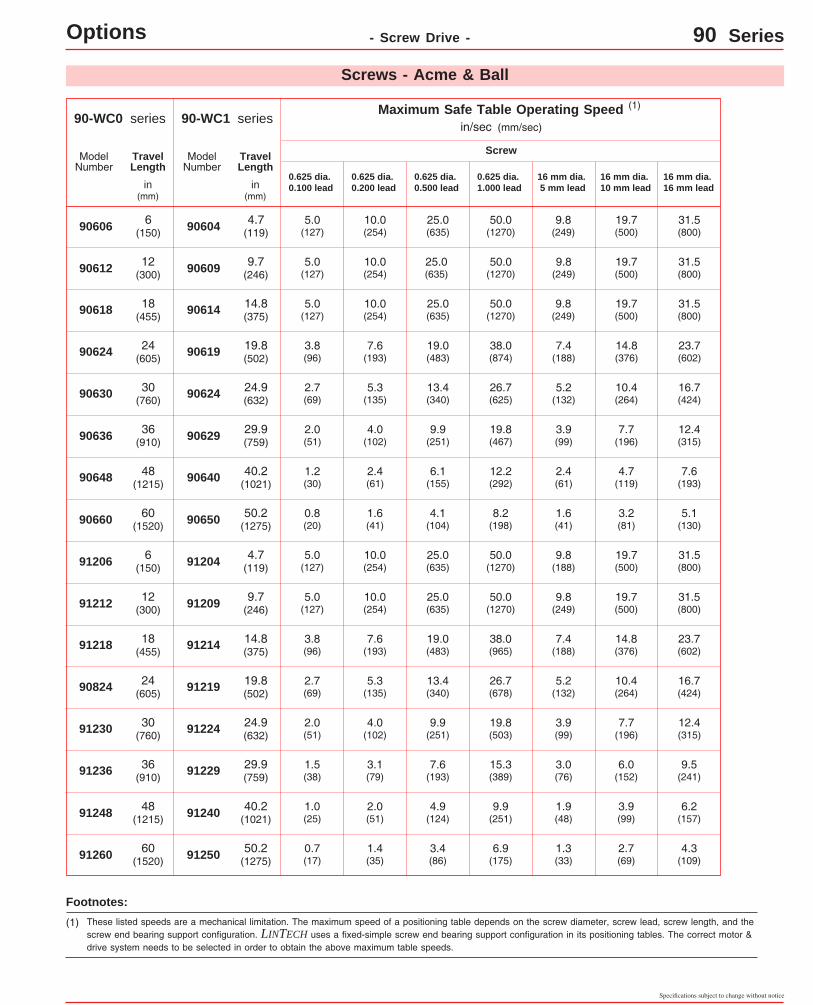
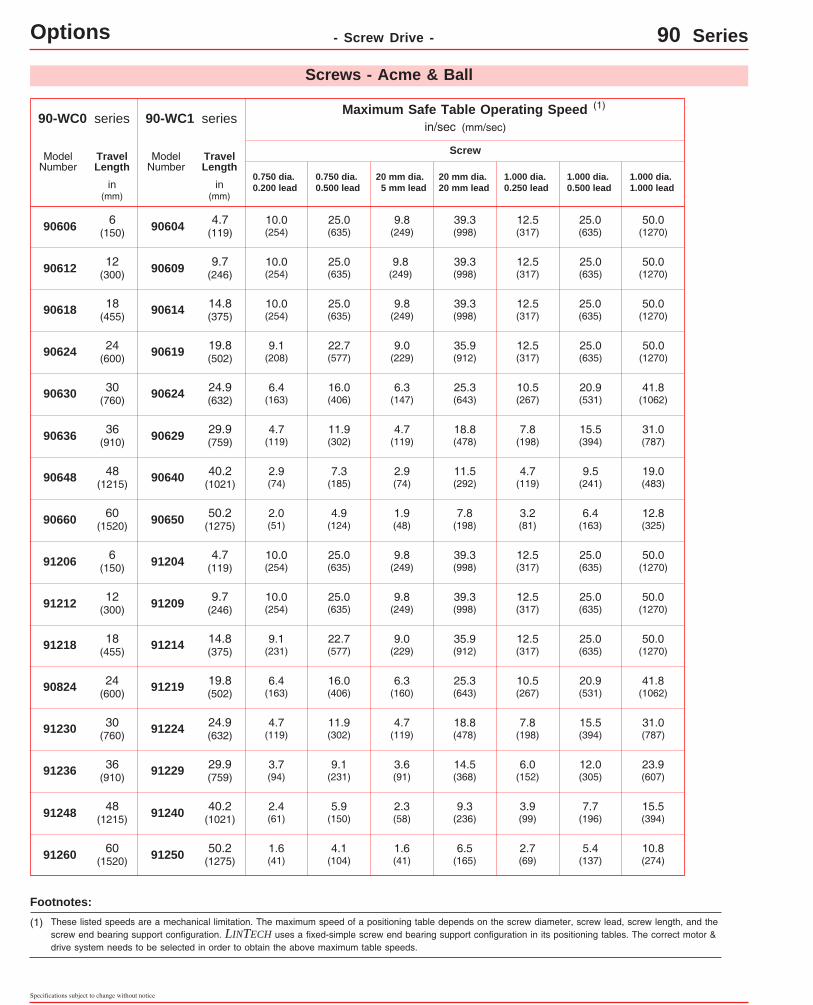
(1) These listed speeds are a mechanical limitation. The maximum speed of a positioning table depends on the screw diameter, screw lead, screw length, and the screw end bearing support configuration. LINTECH uses a fixed-simple screw end bearing support configuration in its positioning tables. The correct motor & drive system needs to be selected in order to obtain the above maximum table speeds.
Footnotes:
ModelNumber
TravelLength
in (mm)
ModelNumber
TravelLength
in (mm)
LINTECH ®
www.LintechMotion.com
- Screw Drive - 90 Series
90-WC1 seriesin/sec (mm/sec)
Maximum Safe Table Operating Speed
90604
90609
90614
90619
90624
90629
90640
91204
91209
91214
91219
91224
91229
91240
(1)
0.750 dia. 0.200 lead
Screw
4.7(119)
9.7(246)
14.8(375)
19.8(502)
24.9(632)
29.9(759)
40.2(1021)
4.7(119)
9.7(246)
14.8(375)
19.8(502)
24.9(632)
29.9(759)
40.2(1021)
10.0(254)
10.0(254)
10.0(254)
9.1(208)
6.4(163)
4.7(119)
2.9(74)
10.0(254)
10.0(254)
9.1(231)
6.4(163)
4.7(119)
3.7(94)
2.4(61)
25.0(635)
25.0(635)
25.0(635)
22.7(577)
16.0(406)
11.9(302)
7.3(185)
25.0(635)
25.0(635)
22.7(577)
16.0(406)
11.9(302)
9.1(231)
5.9(150)
9.8(249)
9.8(249)
9.8(249)
9.0(229)
6.3(147)
4.7(119)
2.9(74)
9.8(249)
9.8(249)
9.0(229)
6.3(160)
4.7(119)
3.6(91)
2.3(58)
39.3(998)
39.3(998)
39.3(998)
35.9(912)
25.3(643)
18.8(478)
11.5(292)
39.3(998)
39.3(998)
35.9(912)
25.3(643)
18.8(478)
14.5(368)
9.3(236)
1.000 dia. 0.250 lead
12.5(317)
12.5(317)
12.5(317)
12.5(317)
10.5(267)
7.8(198)
4.7(119)
12.5(317)
12.5(317)
12.5(317)
10.5(267)
7.8(198)
6.0(152)
3.9(99)
1.000 dia. 0.500 lead
25.0(635)
9.5(241)
25.0(635)
25.0(635)
25.0(635)
20.9(531)
15.5(394)
12.0(305)
7.7(196)
1.000 dia. 1.000 lead
50.0(1270)
19.0(483)
50.0(1270)
50.0(1270)
50.0(1270)
41.8(1062)
31.0(787)
23.9(607)
15.5(394)
15.5(394)
25.0(635)
25.0(635)
20.9(531)
25.0(635)
50.0(1270)
50.0(1270)
50.0(1270)
41.8(1062)
31.0(787)
0.750 dia. 0.500 lead
20 mm dia. 5 mm lead
20 mm dia. 20 mm lead
Screws - Acme & Ball
90-WC0 series
90606
90612
90618
90624
90630
90636
90648
91206
91212
91218
90824
91230
91236
91248
6(150)
12(300)
18(455)
24(600)
30(760)
36(910)
48(1215)
6(150)
12(300)
18(455)
24(600)
30(760)
36(910)
48(1215)
90650 50.2(1275)
2.0(51)
4.9(124)
1.9(48)
7.8(198)
3.2(81)
6.4(163)
12.8(325)90660 60
(1520)
91250 50.2(1275)
1.6(41)
4.1(104)
1.6(41)
6.5(165)
2.7(69)
5.4(137)
10.8(274)91260 60
(1520)
D-20
Specifications subject to change without notice
Options
(1) These listed speeds are a mechanical limitation. The maximum speed of a positioning table depends on the screw diameter, screw lead, screw length, and the screw end bearing support configuration. LINTECH uses a fixed-simple screw end bearing support configuration in its positioning tables. The correct motor & drive system needs to be selected in order to obtain the above maximum table speeds.
Footnotes:
ModelNumber
TravelLength
in (mm)
ModelNumber
TravelLength
in (mm)
LINTECH ®
www.LintechMotion.com
Specifications subject to change without notice
D-21
Options - Screw Drive - 90 Series
SCREWPosition
Accuracy
ROLLED BALL SCREWS
Screw Efficiency
%
BreakawayTorque
oz-in (N-m)
Backlash UnidirectionalRepeatability
BidirectionalRepeatability
0.62
5 in
ch d
ia.
0.20
0 in
ch l
ead
Screws - Acme & Ball
Dyn.Capacity
StaticCapacity
lbs (kg)
lbs (kg)
(1)
20(0,14)
30(0,21)
0.75
0 in
ch d
ia.
0.20
0 in
ch l
ead
25(0,18)
Non-preloaded(S013)
90Preloaded
(S014) 0
60
Non-preloaded Turcite Nut (S015)
Non-preloaded(S017)
90
25(0,18)
40(0,28)
Preloaded(S018)
0
0.75
0 in
ch d
ia.
0.50
00 i
nch
lead
60
35(0,25)
Non-preloaded Turcite Nut (S019)
+ 0.0002(5)
- 0.0082(208)
to
+ 0.0002(5)
- 0.0082(208)
to
+ 0.0002(5)
- 0.0082(208)
to
+ 0.0002(5)
- 0.0082(208)
to
+ 0.0002(5)
- 0.0002(5)
to
+ 0.0002(5)
- 0.0002(5)
to
+/- 0.0002(5)
+/- 0.0002(5)
0.008(203)
0.008(203)
0.008(203)
< 0.008(203)
<
<
<1,900(862)
18,800(8527)
1,710(776)
18,610(8441)
195(88)
1,500(680)
3,450(1565)
24,200(10977)
3,150(1429)
23,855(10820)
195(88)
1,500(680)
(2)
(2)
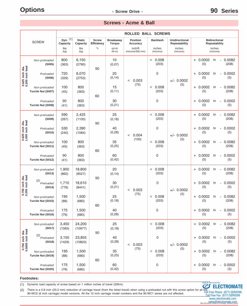
(2) There is a 0.8 inch (20,3 mm) reduction of carriage travel (from the listed travel) when using a preloaded nut with this screw option for all the 90-WC0 (6 inch carriage) model versions. All the 12 inch carriage model numbers and the 90-WC1 series are not affected.
Footnotes:
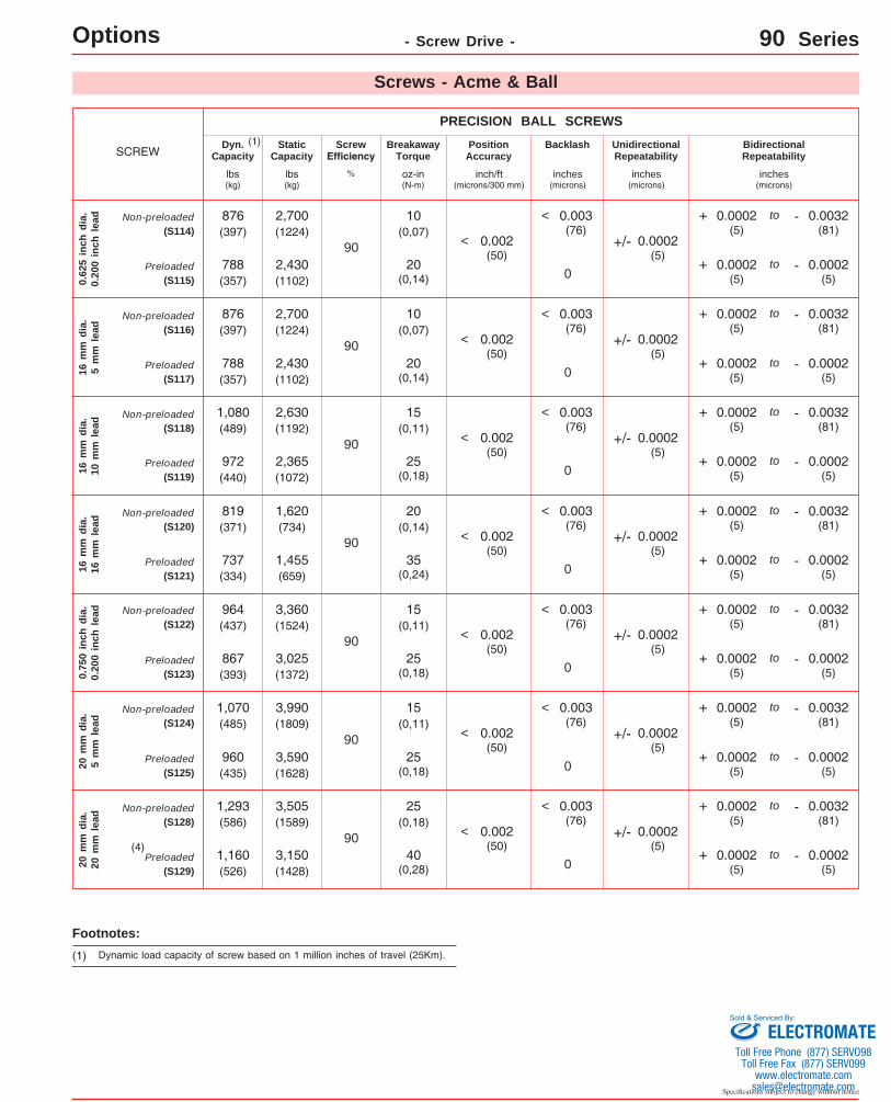
(1) Dynamic load capacity of screw based on 1 million inches of travel (25Km).
(1) Dynamic load capacity of screw based on 1 million inches of travel (25Km).
(2) There is a 1.3 inch (33,0 mm) reduction of carriage travel (from the listed travel) when using a preloaded nut with this screw option for all the 90-WC0 (6 inch carriage) model versions. All the 12 inch carriage model numbers and the 90-WC1 series are not affected.
(1) Dynamic load capacity of screw based on 1 million inches of travel (25Km).
Specifications subject to change without notice
D-24
Options - Screw Drive - 90 Series
Screws - Acme & Ball
(2) The 0.625 inch & 16 mm diameter Ground Ball Screw options are only available in travel lengths where the screw length is less than 47 inches (1194 mm).
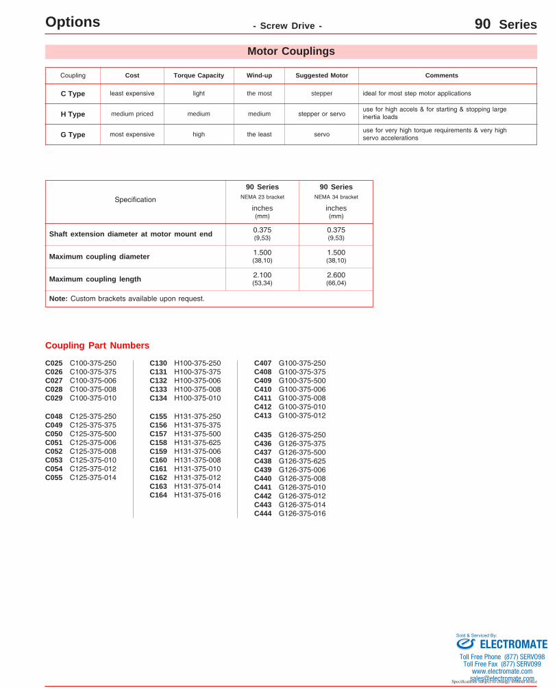
LINTECH provides three different types of couplings that can be used to mount a motor to a positioning table. These couplings compensate for misalignment between the motor shaft & screw shaft extension. This provides for trouble-free opera-tion as long as certain precautions are taken. The connected motor output torque should never exceed the coupling maximum torque capacity. Larger capacity couplings may be required for applications having high accelerations, large back driving loads, high torque output motors, or servo motors.
Motor Couplings
Footnotes: (1) See page D-27 for maximum coupling diameter and length specifications for use with the optional NEMA 23 & 34 motor mounts. Custom
motor mounts can be provided upon request.
(1)Model
Number
DBore
L
C Type - Helical-CutClamp Style Design
(Aluminum)
G Type - Low Wind-up, High TorqueClamp Style Design
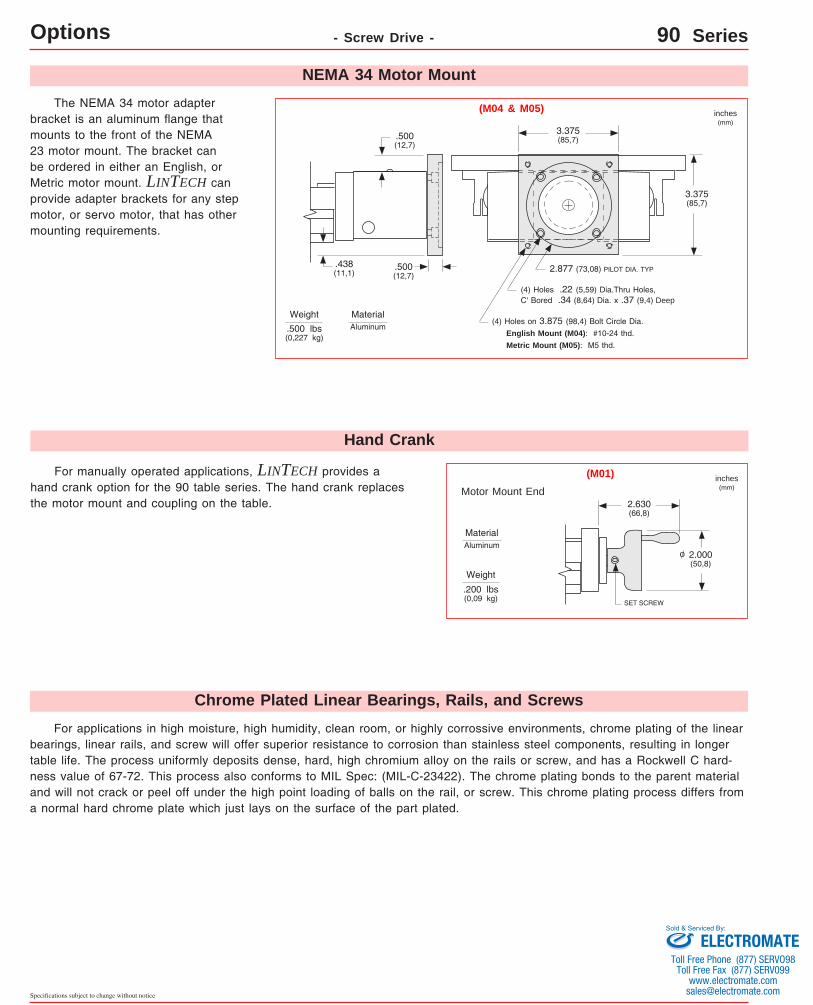
For manually operated applications, LINTECH provides a hand crank option for the 90 table series. The hand crank replaces the motor mount and coupling on the table.
Motor Mount End
The NEMA 34 motor adapter bracket is an aluminum flange that mounts to the front of the NEMA 23 motor mount. The bracket can be ordered in either an English, or Metric motor mount. LINTECH can provide adapter brackets for any step motor, or servo motor, that has other mounting requirements.
Weight
3.375(85,7)
3.375(85,7)
.500(12,7)
.500(12,7)
.438(11,1)
(4) Holes .22 (5,59) Dia.Thru Holes, C' Bored .34 (8,64) Dia. x .37 (9,4) Deep
(4) Holes on 3.875 (98,4) Bolt Circle Dia. English Mount (M04): #10-24 thd. Metric Mount (M05): M5 thd.
.500 lbs(0,227 kg)
SET SCREW
2.000(50,8)
2.630(66,8)
Weight
.200 lbs(0,09 kg)
inches(mm)
inches(mm)
(M01)
(M04 & M05)
NEMA 34 Motor Mount
Hand Crank
MaterialAluminum
MaterialAluminum
o
Chrome Plated Linear Bearings, Rails, and Screws
For applications in high moisture, high humidity, clean room, or highly corrossive environments, chrome plating of the linear bearings, linear rails, and screw will offer superior resistance to corrosion than stainless steel components, resulting in longer table life. The process uniformly deposits dense, hard, high chromium alloy on the rails or screw, and has a Rockwell C hard-ness value of 67-72. This process also conforms to MIL Spec: (MIL-C-23422). The chrome plating bonds to the parent material and will not crack or peel off under the high point loading of balls on the rail, or screw. This chrome plating process differs from a normal hard chrome plate which just lays on the surface of the part plated.
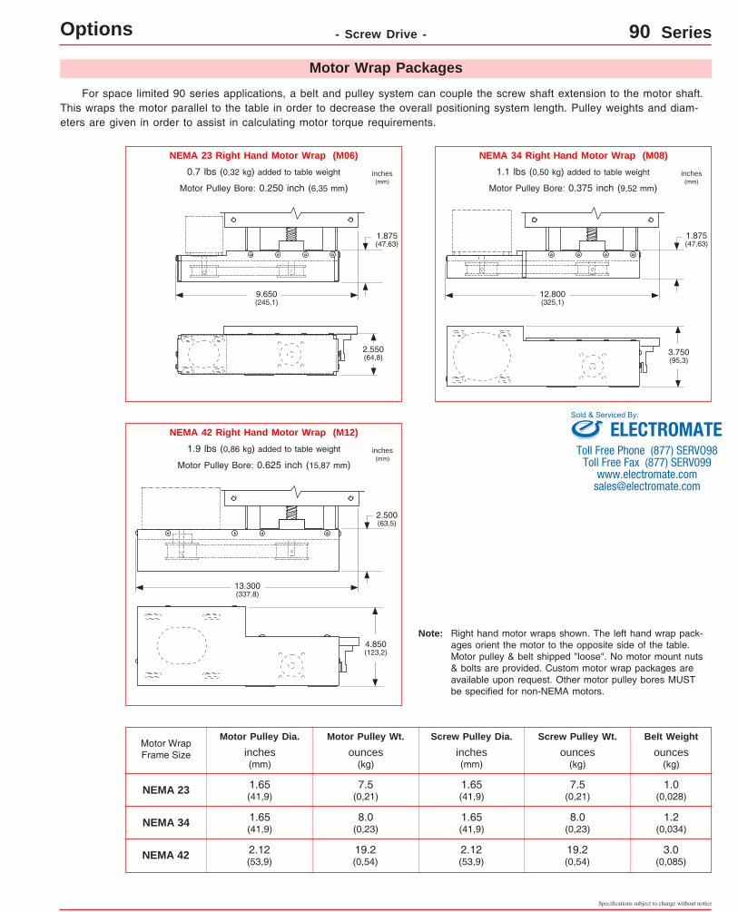
For space limited 90 series applications, a belt and pulley system can couple the screw shaft extension to the motor shaft. This wraps the motor parallel to the table in order to decrease the overall positioning system length. Pulley weights and diam-eters are given in order to assist in calculating motor torque requirements.
Motor Wrap Frame Size
NEMA 23
NEMA 34
Motor Pulley Dia. Motor Pulley Wt. Screw Pulley Dia. Screw Pulley Wt. Belt Weight
inches(mm)
1.65(41,9)
1.65(41,9)
inches(mm)
ounces(kg)
ounces(kg)
ounces(kg)
1.65(41,9)
1.65(41,9)
7.5(0,21)
8.0(0,23)
7.5(0,21)
8.0(0,23)
1.0(0,028)
1.2(0,034)
NEMA 34 Right Hand Motor Wrap (M08)
NEMA 42 Right Hand Motor Wrap (M12)
Motor Wrap Packages
NEMA 23 Right Hand Motor Wrap (M06)
0.7 lbs (0,32 kg) added to table weight inches(mm)
NEMA 42 2.12(53,9)
2.12(53,9)
19.2(0,54)
19.2(0,54)
3.0(0,085)
Right hand motor wraps shown. The left hand wrap pack-ages orient the motor to the opposite side of the table. Motor pulley & belt shipped "loose". No motor mount nuts & bolts are provided. Custom motor wrap packages are available upon request. Other motor pulley bores MUST be specified for non-NEMA motors.
Note:
Motor Pulley Bore: 0.250 inch (6,35 mm)
1.1 lbs (0,50 kg) added to table weight inches(mm)
Motor Pulley Bore: 0.375 inch (9,52 mm)
1.9 lbs (0,86 kg) added to table weight inches(mm)
For vertical table applications, or for those applications requir-ing the load to be locked securely in place, an electric brake may be mounted to the positioning table. The 90 series will have the brake mounted to the screw shaft extension located on the table end, op-posite the motor mount bracket. With proper wiring from a control sys-tem, this power-off friction brake can ensure that the carriage is firmly held in place, when no electric power is applied to the brake. When power is applied to the brake, the brake is opened or "released". For proper emergency braking of the positioning table, this electric brake needs to be interfaced to a position controller or relay network. LINTECH also provides 24 & 90 VDC power supplies which can be used to power the brakes.
Table end opposite motor mount bracket
Brake(B01 or B02)
90 Series
24 VDC
Model Number
B01
Holding Force Excitation Voltage
volts
Current
amps
0.733
Weight
Brakes
lbs(kg)
in-lbs(N-m)
1.4(0,62)
18(2,0)
2.46(62,5)
1.75(44,5)
2.46(62,5) 90 VDCB02 0.178 1.4
(0,62)18
(2,0)
inches(mm)
.02(0,5)
This power-off electric brake MUST NOT be engaged when the positioning table is in motion. Moving the table with the brake applied could damage the brake and the positioning table. Also, continuous use of this brake to stop a table (load) that is in motion could damage the brake and the posi-tioning table. Dynamic braking of a positioning table should be done by the motor and not the brake.
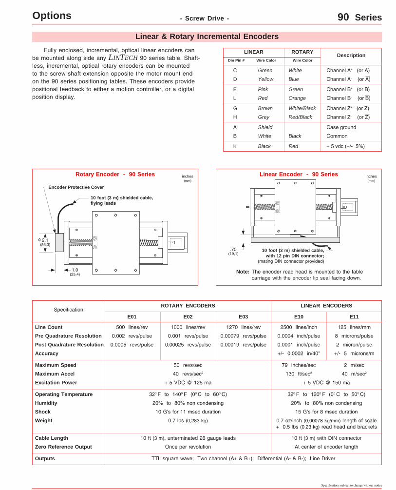
Fully enclosed, incremental, optical linear encoders can be mounted along side any LINTECH 90 series table. Shaft-less, incremental, optical rotary encoders can be mounted to the screw shaft extension opposite the motor mount end on the 90 series positioning tables. These encoders provide positional feedback to either a motion controller, or a digital position display.
The encoder read head is mounted to the table carriage with the encoder lip seal facing down.
Note:
Linear Encoder - 90 SeriesRotary Encoder - 90 Series
.75(19,1)
2.1(53,3)
1.0(25,4)
Line Count 500 lines/rev
SpecificationE01 E02
1000 lines/rev
Pre Quadrature Resolution 0.002 revs/pulse 0.001 revs/pulse
Post Quadrature Resolution 0.0005 revs/pulse 0,00025 revs/pulse
Accuracy
Maximum Speed 50 revs/sec
Maximum Accel 40 revs/sec2
E03
1270 lines/rev
0.00079 revs/pulse
0.00019 revs/pulse
2500 lines/inch
E10 E11
125 lines/mm
0.0004 inch/pulse 8 microns/pulse
0.0001 inch/pulse 2 micron/pulse
+/- 0.0002 in/40" +/- 5 microns/m
79 inches/sec 2 m/sec
130 ft/sec2 40 m/sec2
Excitation Power + 5 VDC @ 125 ma + 5 VDC @ 150 ma
Operating Temperature 320 F to 1200 F (00 C to 500 C)320 F to 1400 F (00 C to 600 C)
Humidity 20% to 80% non condensing20% to 80% non condensing
Shock 10 G's for 11 msec duration 15 G's for 8 msec duration
Weight 0.7 lbs (0,283 kg) 0.7 oz/inch (0,00078 kg/mm) length of scale + 0.5 lbs (0,23 kg) read head and brackets
Cable Length 10 ft (3 m), unterminated 26 gauge leads 10 ft (3 m) with DIN connector
Zero Reference Output Once per revolution At center of encoder length
Outputs TTL square wave; Two channel (A+ & B+); Differential (A- & B-); Line Driver
Channel A+ (or A)White
Blue
Green
Yellow
Green
Orange
Pink
Red
White/Black
Red/Black
Brown
Grey
+ 5 vdc (+/- 5%)
Common
Red
Black
Shield
White
Case ground
Black
ROTARYLINEARWire Color
Description
Channel A- (or A)
Channel B+ (or B)
Channel B- (or B)
Channel Z+ (or Z)
Channel Z- (or Z)
C
D
E
L
G
H
A
K
B
Din Pin #
ROTARY ENCODERS LINEAR ENCODERS
Linear & Rotary Incremental Encoders
Encoder Protective Cover
10 foot (3 m) shielded cable,flying leads
10 foot (3 m) shielded cable,with 12 pin DIN connector;