8
Page 1 www.dsiventures.com Liquid Cooling Theory and Application in Systems Design Theoretical Framework and Characteristics Jason D. Carr

Page 1 www.dsiventures.com
Liquid Cooling Theory and Application in Systems Design
Theoretical Framework and Characteristics Jason D. Carr

Page 2 www.dsiventures.com
Introduction A growing number of engineering applications at different scales, from nuclear reactors to industrial heat exchangers to electronic devices to micro machinery, have thermal management concerns. Depending upon the requirement, cooling is commonly achieved by air or liquids, with each coolant category having its own suitability, advantages and disadvantages. Liquid cooling offers advantages of rapid and efficient heat removal from a source, often with a lower thermal gradient, due to high specific heat capacities of many engineering fluids. Liquids, and especially water, are also sometimes used in evaporative cooling applications, where their high latent heat of vaporization allows removal of large quantities of heat in confined spaces. This paper broadly outlines various types of liquid coolants, their theoretical basis and performance characteristics, as well as their applications. Theoretical Framework Fluid flow can be laminar (steady state) or turbulent, and heat might be transferred with and without phase change. In addition, the flow regime might be treated as Newtonian or non-Newtonian. Appropriate theoretical and empirical heat transfer equations have been developed for different velocity profiles, flow regimes and flow geometries. For the ideal case of fluid flow in a shell-and-tube exchanger, heat is transferred by radiation and convection to tubes via conduction through tube walls and by forced conduction from the internal wall surface to the bulk fluid. The basic equation governing all such heat transfer is 𝑄 = 𝑈𝐴∆𝑇 (Eq. 1) where Q represents heat transferred in unit time, U represents overall heat transfer coefficient, A represents available surface area and ΔT represents temperature gradient between the source and the sink (or the inlet and the outlet). If multiple fluids or separating walls are used, then the overall coefficient U can be decomposed into individual coefficients h, each representing a particular medium. [1] In instances of conductive heat transfer through several layers of materials, the thermal resistances can be added in series to obtain the total temperature gradient. This is shown in Figure 1 below, where xi represent media thickness and ki represent thermal conductivities:
Figure 1: Conductive heat transfer through composite media. [2] With reference to the above figure, the thermal gradient T1 – T4 is
Page 3 www.dsiventures.com
𝑇! − 𝑇! =!!!!!
+ !!!!!
+ !!!!!
𝑄 (Eq. 2) where Q becomes the ratio of total driving force to total thermal resistance per unit area. [2] In instances of convective transfer, which is often the principal mechanism in liquid cooling, the heat transfer coefficient may be expressed as a dimensionless relation known as the Nusselt number, or as a dimensional equation. Convection is distinguished between natural (fluid movement caused by the transfer process itself) or forced (fluid movement caused by an externally applied force); in the former, the Nusselt number for external spaces is
𝑁𝑢 = 0.825+ !.!"#!!!/!
!! !.!"#/!" !/!" !/!"
! (Eq. 3)
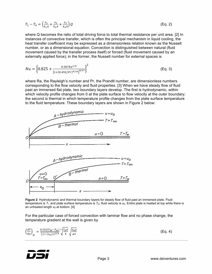
where Ra, the Rayleigh’s number and Pr, the Prandtl number, are dimensionless numbers corresponding to the flow velocity and fluid properties. [3] When we have steady flow of fluid past an immersed flat plate, two boundary layers develop. The first is hydrodynamic, within which velocity profile changes from 0 at the plate surface to flow velocity at the outer boundary; the second is thermal in which temperature profile changes from the plate surface temperature to the fluid temperature. These boundary layers are shown in Figure 2 below:
Figure 2: Hydrodynamic and thermal boundary layers for steady flow of fluid past an immersed plate. Fluid temperature is T∞ and plate surface temperature is Tw; fluid velocity is u0. Entire plate is heated at top while there is an unheated length x0 at bottom. [4] For the particular case of forced convection with laminar flow and no phase change, the temperature gradient at the wall is given by !"!" !
= !.!!" !!!!!!! !!/! !/!!
!!!!
! !!!!"
(Eq. 4)
Page 4 www.dsiventures.com
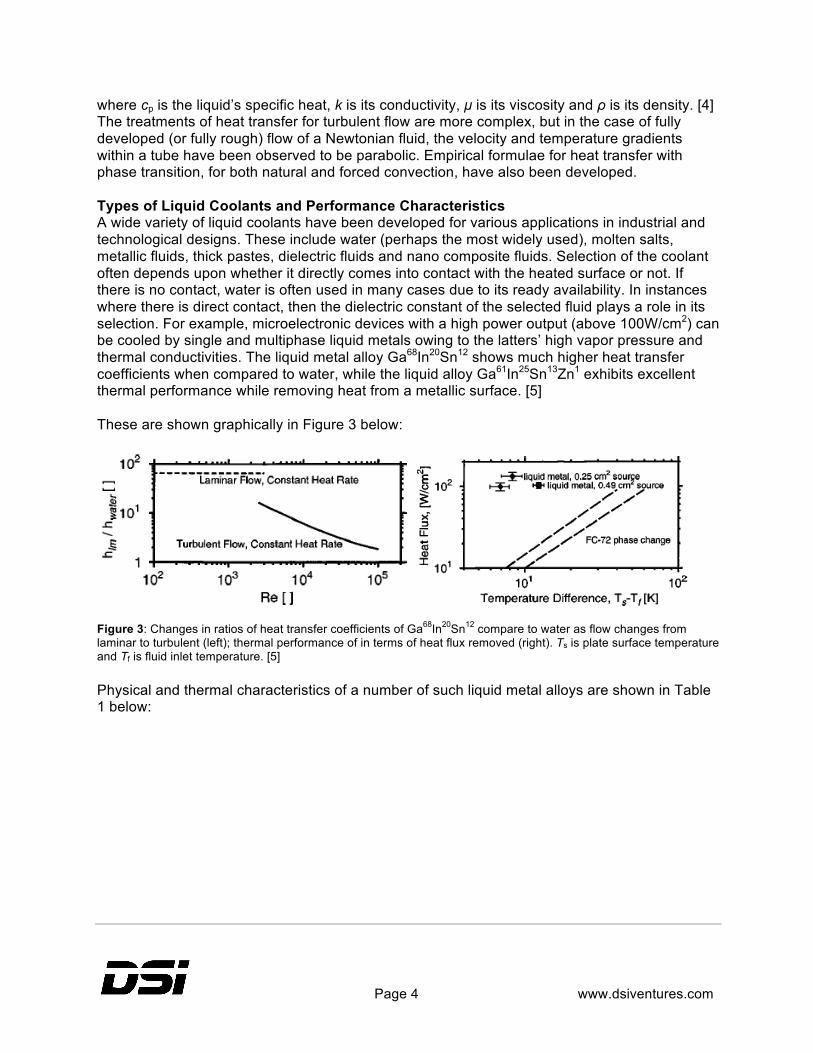
where cp is the liquid’s specific heat, k is its conductivity, µ is its viscosity and ρ is its density. [4] The treatments of heat transfer for turbulent flow are more complex, but in the case of fully developed (or fully rough) flow of a Newtonian fluid, the velocity and temperature gradients within a tube have been observed to be parabolic. Empirical formulae for heat transfer with phase transition, for both natural and forced convection, have also been developed. Types of Liquid Coolants and Performance Characteristics A wide variety of liquid coolants have been developed for various applications in industrial and technological designs. These include water (perhaps the most widely used), molten salts, metallic fluids, thick pastes, dielectric fluids and nano composite fluids. Selection of the coolant often depends upon whether it directly comes into contact with the heated surface or not. If there is no contact, water is often used in many cases due to its ready availability. In instances where there is direct contact, then the dielectric constant of the selected fluid plays a role in its selection. For example, microelectronic devices with a high power output (above 100W/cm2) can be cooled by single and multiphase liquid metals owing to the latters’ high vapor pressure and thermal conductivities. The liquid metal alloy Ga68In20Sn12 shows much higher heat transfer coefficients when compared to water, while the liquid alloy Ga61In25Sn13Zn1 exhibits excellent thermal performance while removing heat from a metallic surface. [5] These are shown graphically in Figure 3 below:
Figure 3: Changes in ratios of heat transfer coefficients of Ga68In20Sn12 compare to water as flow changes from laminar to turbulent (left); thermal performance of in terms of heat flux removed (right). Ts is plate surface temperature and Tf is fluid inlet temperature. [5] Physical and thermal characteristics of a number of such liquid metal alloys are shown in Table 1 below:

Page 5 www.dsiventures.com
Table 1: Thermal and physical properties of various liquid metals employed in heat transfer. [5]
At the other end of the complexity scale, molten salts of fluorides, chlorides and nitrates are used for heat removal from the core of some nuclear reactors. A primary heat exchanger uses these salts for removing heat directly from the dissolved fuel, while a secondary heat exchanger containing pressurized steam is used to remove heat from the primary loop. The primary performance characteristic of such coolants is their ability to remove non-uniformly generated heat through both radiated and convective heat transfer. [6] Recently, a great deal of research has been conducted into coolants that have a nano disperse phase, for application in complex electronic circuits and devices. Nano particles of copper or aluminum, upon being dispersed into a liquid phase, create coolants that have not only better thermal and rheological properties, but also substantially improved thermal conductivity and no extra pressure drop. The nano disperse phase constitutes less than 1% of total volume; if a molten metal alloy is used as the bulk liquid carrier, then thermal conductivities improve by up to 2.5 times. [7] This is shown in Figure 4 below:
Figure 4: Increased thermal conductivities when different nano particle species are dispersed in liquid-gallium coolant. Keff is thermal conductivity of the nano phase and Kf is that of the base phase. [7]

Page 6 www.dsiventures.com
Similarly, multi-walled carbon nano tubes (MWCNTs) dispersed in water or ethylene glycol at 0.1-0.4wt.% have shown much greater heat exchange capacities when used as radiator coolant fluids. [8] Finally, low viscosity synthetic hydrocarbon dielectric fluids have successfully been used to cool electronic circuitry, high-power vacuum tubes, underwater hydraulics, and electric drivetrain motors. Existing and Future Applications It is not possible to mention all the varied applications of liquid coolants, thus only a few specialized and technological ones will be mentioned. The reason that liquid cooling is especially efficient for electronic components with high heat fluxes is that it can be used as a heat sink with micro-channels. Micro rectangular and trapezoidal grooves on silicon wafers can be designed with geometries optimized for rapid and efficient heat removal. The Reynolds number for flows within such channels is usually above 10,000 and pressure drops, which depend on their aspect ratios, are between 490 and 2940 Pa. The design of such a micro-channel block having an aspect ratio of 7.7 is shown in Figure 5 below:
Figure 5: Dimensions of a micro-channel heat sink (left); the actual assembly (right). [9] Another common application area is the use of coils or ducts containing fluids in order to dissipate heat from electromagnetic coils. Low viscosity fluids are used with copper tubes having a large number of windings and improved heat dissipation that improves the electromagnetic field strength. [10] Liquid immersion of circuitry via synthetic paraffins and isoparaffins have proven to be technologically viable alternatives for thermal management as well. Due to the reasons discussed above, liquid cooling is employed extensively in server farms, for individual high performance computers, and in supercomputing environments. Liquid cooling is also expected to play an important role in many future applications such as robotics, quantum computing, high sensitivity optical and radio telescopes, and in astro-

Page 7 www.dsiventures.com
engineering. For example a combination of gadopentetic acid and D2O was used as a heat sink to cool a quantum system consisting of glycine and glutamate. [11] Cryogenic cooling systems consisting of liquid helium, nitrogen or other fluids are regularly employed to increase the sensitivity of telescopes and many other astronomy and physics equipment. Another novel application approach currently under research is the liquid cooling of personal, wearable garments. Also referred to as liquid cooled garments (LCGs), these mostly use water as the coolant. They are outfitted with a pump and a heat exchanger, where heat carried away from the body surface is exchanged with ice or another temperature sink. [12] Conclusion Liquid cooling technology is an important part of modern engineering applications, both at industrial and personal levels. Many different fluids have been developed for different application purposes, and research is ongoing to identify the material properties of novel liquid coolants. It is expected that their use will increase in the near future and lead to more powerful and efficient electronics and other devices.
Page 8 www.dsiventures.com
Reference
[1] Halliday, D., Resnick, R., & Walker, J. (2014). Fundamentals of Physics, 10th Ed. Chichester: John Wiley & Sons, Inc.
[2] Coulson, J. M. & Richardson, J. F. (1999). Fluid Flow, Heat Transfer and Mass Transfer, 6th Ed. Massachusetts: Butter worth–Heinemann.
[3] Maloney, J. O. (2008). Perry’s Chemical Engineers’ Handbook, 8th Ed. New York: McGraw-Hill.
[4] McCabe, W. L., Smith, J. C., & Harriott, P. (1993). Unit operations of chemical engineering, 5th Ed. New York: McGraw-Hill.
[5] Miner, A. & Ghoshal, U. (2004). Cooling of high-power-density microdevices using liquid metal coolants. Applied Physics Letters, 85(3), 506-508.
[6] Qian, L. et al. (2010). Numerical research on natural convection in molten salt reactor with non-uniformly distributed volumetric heat generation. Nuclear Engineering and Design, 240, 796–806.
[7] Ma, K.-Q. & Liu, J. (2007). Nano liquid-metal fluid as ultimate coolant. Physics Letters A, 361, 252–256.
[8] Teng, T.-P. & Yu, C.-C. (2013). Heat dissipation performance of MWCNTs nano-coolant for vehicle. Experimental Thermal and Fluid Science, 49, 22–30.
[9] Chiu, H.-C. et al. (2011). The heat transfer characteristics of liquid cooling heatsink containing microchannels. International Journal of Heat and Mass Transfer, 54, 34–42.
[10] Ricci, L. et al. (2013). A current-carrying coil design with improved liquid cooling arrangement. Review of Scientific Instruments, 84, 065115 1-4.
[11] Elias, Y. et al. (2011). Heat-bath cooling of spins in two amino acids. Chemical Physics Letters, 517, 126–131.
[12] Yazdi, M. M. & Sheikhzadeh, M. (2014). Personal cooling garments: a review. The Journal of The Textile Institute, 1-20.


