44
Liquid Crystal Polarimeter User Manual Revision 2.10
Liquid Crystal Polarimeter
User Manual Revision 2.10
Information in this document is subject to change without notice. Meadowlark
Optics may have patents, patent applications, trademarks, copyrights, or other
intellectual property rights covering subject matter in this document including
US Patent # 6,744,509. Except as expressly provided in any written license
agreement from Meadowlark Optics, the furnishing of this document does not
give you any license to these patents, trademarks, copyrights, or other
intellectual property. Please contact Meadowlark Optics for a list of applicable
patents, trademarks, and/or copyrights.
Copyright © 2002-2012 Meadowlark Optics, Incorporated. All rights reserved.
Printed in Colorado, USA

Polarimeter User Manual rev 2.10
Contents
Quick Start Guide ................................................................................................. i
1 Stokes Polarimetry Using LCVRs
1.1 Stokes Polarimetry ...................................................................................... 1
1.2 Measuring the S1 Component of the Stokes Vector ................................... 2
1.3 Measuring the S3 Component of the Stokes Vector ................................... 3
1.4 Measuring the S2 Component of the Stokes Vector ................................... 3
1.5 Parameters calculated from Stokes vector components .............................. 4
1.6 Summary ..................................................................................................... 4
1.7 References .................................................................................................. 5
2 Hardware Setup and Configuration
2.1 Laboratory and system requirements for the D3000 .................................. 5
2.2 Setup procedure for the D3000 ................................................................... 5
3 Using PolarVIEW 3000
3.1 Startup Procedure ........................................................................................ 7
3.2 PolarVIEW 3000 User Interface ................................................................. 8
3.2.1 Main Functions ........................................................................................... 8
3.2.2 Polarization Data Display ........................................................................... 8
3.2.3 Temperature Information ............................................................................ 9
3.2.4 Light Levels ................................................................................................ 9
3.2.5 Save Function ............................................................................................. 9
3.2.6 Display Region ......................................................................................... 10
3.3 Wavelength Calibration Screen ................................................................ 13
3.3.1 Calibration Functions ................................................................................ 13
3.4 Temperature Screen .................................................................................. 15
3.4.1 Temperature Functions ............................................................................. 15
4 Measurement Practices
4.1 Getting ready for measurements ............................................................... 16
4.2 Temperature control .................................................................................. 16
4.3 Dark signal reading ................................................................................... 16
4.4 Photodiode gain control ............................................................................ 16
4.5 Wavelength selection ................................................................................ 16
4.6 Start measurement and warm-up period ................................................... 16
4.7 Smoothing ................................................................................................. 16
4.8 Sampling and recording to a file ............................................................... 17
5 Laboratory Considerations
5.1 Optical alignment ...................................................................................... 17
5.2 Calibration ................................................................................................ 18

Polarimeter User Manual rev 2.10
6 User Development with LabVIEW™ VI’s Provided by Meadowlark
Optics, Inc ................................................................................................ 21
7 General Specifications ............................................................................ 21
Appendix A: Frequently Asked Questions ...................................................... 22
Appendix B: Firmware Updater ....................................................................... 23
Appendix C: Software Licensing ...................................................................... 27
Software License Agreement ............................................................................... 27
Trademarks .......................................................................................................... 29
Polarimeter User Manual rev 2.10 i
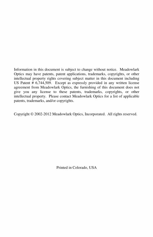
Requires a computer running Microsoft® Windows
® XP service pack 3 or later.
1) Place the included CD in the CD-ROM drive. The CD autorun menu
should launch. Click on the “Install PolarVIEW…” button. If the autorun
menu doesn’t launch, run setup.exe in the installer directory on the CD.
2) Before the Polarimeter controller is powered on or connected to a PC via
USB, the USB driver must first be installed. The installer is located in the
USB drivers directory on the CD, or the “Install USB Driver“ menu option
in the CD menu may be selected. There are separate installers for 32 bit
and 64 bit drivers.
3) Plug the included USB cable into the appropriate connector on the D3000
control module. Plug the other end into an available USB port on the
COMPUTER.
4) Carefully connect the optics head to the control module using the included
25-pin cable with the printing on the connector facing up.
5) Plug the power supply cable into the power connector on the D3000 control
module, then connect the power supply to a properly grounded outlet.
6) Turn on the Polarimeter controller. The POWER light will illuminate and
the STATUS light will blink during initialization; after initialization, the
STATUS light will turn off. The POWER light remains illuminated until
the power is turned off.
7) Start the PolarVIEW 3000 software by clicking Start � Programs �
Meadowlark Optics � PolarVIEW 3000.

Polarimeter User Manual rev 2.10 ii
Page intentionally left blank

Polarimeter User Manual rev 2.10 1
1. Stokes Polarimetry Using LCVRs
Analysis of polarized light is important in many applications and Meadowlark
Optics’ Liquid Crystal Variable Retarders are electrically tunable waveplates,
which can be used for such analyses. The typical polarimeter uses electric
motors and spinning waveplates that can induce noise into sensitive
measurements. The Meadowlark Optics Polarimeter, being a solid-state device,
has no motors and does not produce any vibration.
1.1 Stokes Polarimetry The Stokes parameters comprise a four-component vector that completely
characterizes the polarization of light. The components of the Stokes vector are
simple combinations of the intensities of linear and circular polarization
components of the light:
0
1
2
3
S
S
S
S
=
S
where:
S0 = total light intensity
S1 = intensity difference between horizontal and vertical linearly polarized
components (horizontal – vertical)
S2 = intensity difference between linearly polarized components oriented at
±45° (+45 – (-45))
S3 = intensity difference between right and left circular components (right –
left)
The unit for each Stokes vector component is Watts/meter2.
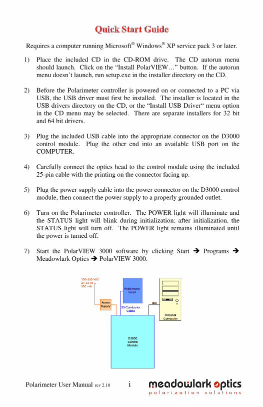
The notion of ellipticity and handedness of polarization is important. Figure 1
shows how a quarter-wave retarder can be used to convert linear polarization
into circular polarization. In both the left- and right-hand cases, a linear state is
incident upon a quarter-wave retarder with the fast axis oriented at +45°,
however the orientation of the input linear state is changed from Vertical to
Horizontal. In each case, the linear state is rendered as two components, one
parallel and the other perpendicular to the fast axis of the retarder. The top-most
drawings in Figure 1 show how the retarder introduces a phase delay by
retarding the component perpendicular to the fast axis. The lower-most
drawings in Figure 1 show precession of the vector as light propagates from the
retarder. In Figure 1a, vertical polarized light is converted to left-hand circular
Polarimeter User Manual rev 2.10 2
polarization, and in Figure 1b, horizontal polarized light is converted to right-
hand circular polarization.
Figure 1. Left and right circular polarization states
Note the orientation of the input linear polarization (Purple arrow)
Notice also that angles (e.g. the orientation of the retarder’s fast axis) and
rotational directions (clockwise and counterclockwise) are from the perspective
looking toward the source.
The next three examples describe how one or two LCVRs can be combined with
a beam-splitting polarizer to measure each of the Stokes parameters.
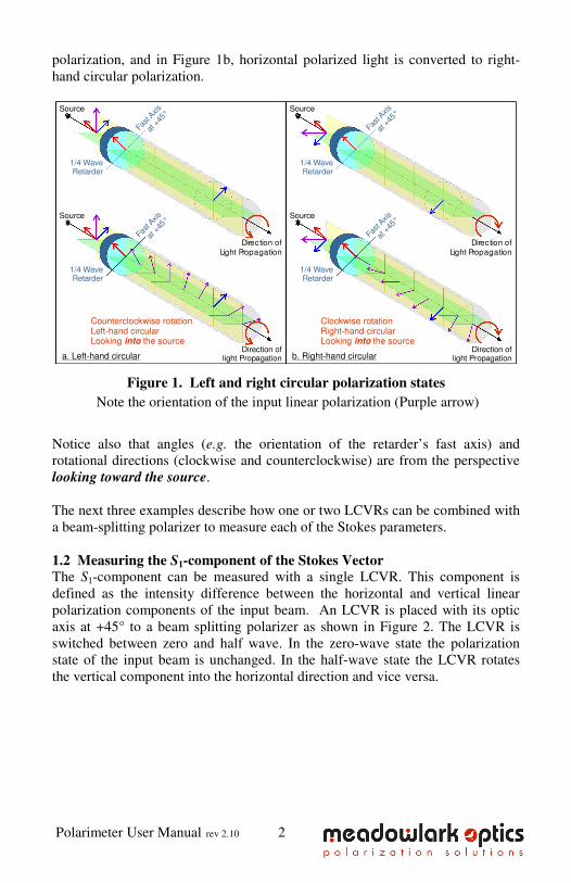
1.2 Measuring the S1-component of the Stokes Vector The S1-component can be measured with a single LCVR. This component is
defined as the intensity difference between the horizontal and vertical linear
polarization components of the input beam. An LCVR is placed with its optic
axis at +45° to a beam splitting polarizer as shown in Figure 2. The LCVR is
switched between zero and half wave. In the zero-wave state the polarization
state of the input beam is unchanged. In the half-wave state the LCVR rotates
the vertical component into the horizontal direction and vice versa.
Fast A
xis
at +
45°
Fast A
xis
at +
45°
Direction oflight Propagation
Clockwise rotationRight-hand circularLooking the sourceinto
Source
Source
Direction of
Light Propagation
b. Right-hand circular
1/4 WaveRetarder
1/4 WaveRetarder
Counterclockwise rotationLeft-hand circularLooking the sourceinto
Fast A
xis
at +
45°
Fast A
xis
at +
45°
Source
Source
Direction oflight Propagation
Direction of
Light Propagation
a. Left-hand circular
1/4 WaveRetarder
1/4 WaveRetarder
Polarimeter User Manual rev 2.10 3
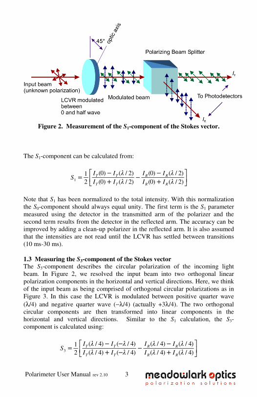
Figure 2. Measurement of the S1-component of the Stokes vector.
The S1-component can be calculated from:
1
(0) ( / 2) (0) ( / 2)1
2 (0) ( / 2) (0) ( / 2)T T R R
T T R R
I I I IS
I I I I
− λ − λ= − + λ + λ
Note that S1 has been normalized to the total intensity. With this normalization
the S0-component should always equal unity. The first term is the S1 parameter
measured using the detector in the transmitted arm of the polarizer and the
second term results from the detector in the reflected arm. The accuracy can be
improved by adding a clean-up polarizer in the reflected arm. It is also assumed
that the intensities are not read until the LCVR has settled between transitions
(10 ms-30 ms).
1.3 Measuring the S3-component of the Stokes vector The S3-component describes the circular polarization of the incoming light
beam. In Figure 2, we resolved the input beam into two orthogonal linear
polarization components in the horizontal and vertical directions. Here, we think
of the input beam as being comprised of orthogonal circular polarizations as in
Figure 3. In this case the LCVR is modulated between positive quarter wave
(λ/4) and negative quarter wave (−λ/4) (actually +3λ/4). The two orthogonal
circular components are then transformed into linear components in the
horizontal and vertical directions. Similar to the S1 calculation, the S3-
component is calculated using:
3
( / 4) ( / 4) ( / 4) ( / 4)1
2 ( / 4) ( / 4) ( / 4) ( / 4)T T R R
T T R R
I I I IS
I I I I
λ − −λ λ − λ= − λ + −λ λ + λ
Polarimeter User Manual rev 2.10 4
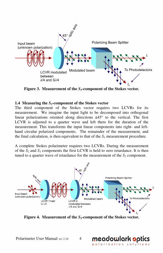
Figure 3. Measurement of the S3-component of the Stokes vector.
1.4 Measuring the S2-component of the Stokes vector The third component of the Stokes vector requires two LCVRs for its
measurement. We imagine the input light to be decomposed into orthogonal
linear polarizations oriented along directions ±45° to the vertical. The first
LCVR is adjusted to a quarter wave and left there for the duration of the
measurement. This transforms the input linear components into right- and left-
hand circular polarized components. The remainder of the measurement, and
the final calculation, is then equivalent to that of the S3 measurement procedure.
A complete Stokes polarimeter requires two LCVRs. During the measurement
of the S2 and S3 components the first LCVR is held to zero retardance. It is then
tuned to a quarter wave of retardance for the measurement of the S2 component.
Figure 4. Measurement of the S2-component of the Stokes vector.
Polarimeter User Manual rev 2.10 5
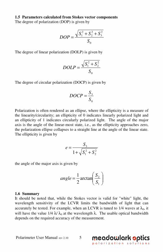
1.5 Parameters calculated from Stokes vector components The degree of polarization (DOP) is given by
0
2
3
2
2
2
1
S
SSSDOP
++=
The degree of linear polarization (DOLP) is given by
0
2
2
2
1
S
SSDOLP
+=
The degree of circular polarization (DOCP) is given by
0
3
S
SDOCP =
Polarization is often rendered as an ellipse, where the ellipticity is a measure of
the linearity/circularity; an ellipticity of 0 indicates linearly polarized light and
an ellipticity of 1 indicates circularly polarized light. The angle of the major
axis is the angle of the linear-most state, i.e., as the ellipticity approaches zero,
the polarization ellipse collapses to a straight line at the angle of the linear state.
The ellipticity is given by
2
2
2
1
3
1 SS
Se
++
=
the angle of the major axis is given by
=
1
2arctan2
1
S
Sangle
1.6 Summary It should be noted that, while the Stokes vector is valid for "white" light, the
wavelength sensitivity of the LCVR limits the bandwidth of light that can
accurately be tested. For example, when an LCVR is tuned to 1/4 waves at λ0, it
will have the value 1/4 λ/ λ0 at the wavelength λ. The usable optical bandwidth
depends on the required accuracy of the measurement.
Polarimeter User Manual rev 2.10 6
1.7 References 1. T. Baur, D.E. Elmore, R.H. Lee, C.W. Querfeld, and S.R. Rogers, "Stokes
II - A New Polarimeter for Solar Observations," Solar Physics , 70, 395
(1981).
2. T. Baur, "Optical Polarimeters for Solar Research," Opt. Eng. 20, 2 (1981).
3. D.S. Kliger, J.W. Lewis, and C.E. Randall, "Polarized Light in Optics and
Spectroscopy, (Academic press, San Diego., California, 1990).
4. W.A. Shurcliff, "Polarized Light: Production and Use", (Harvard University
Press, Cambridge, Mass., 1966).
5. D. Clarke, J.F. Grainger, "Polarized Light and Optical Measurement",
(Pergamon Press, Oxford, 1971). Chapter 4 gives an excellent treatment of
polarimetry.
6. M. Born, E. Wolf, "Principles of Optics", (Pergamon Press, Oxford, 1980).
2. Hardware Setup and Configuration
2.1 Laboratory and system requirements for the D3000
• 100-240 VAC, 47-63 Hz 500 mA utility power.
• A COMPUTER with an available USB port.
• Minimum COMPUTER requirements to run the PolarVIEW 3000
Liquid Crystal Polarimeter software are an 866-MHz Pentium® III
processor, 256 MB RAM, 350 MB hard drive space, 800x600 pixel,
16-bit color or better graphics display, a CD-ROM, and Microsoft®
Windows® XP / Vista / 7. (32 or 64 bit versions are supported)
• Recommended COMPUTER specifications are a 1-GHz Pentium® III
processor, 512 MB RAM, 350 MB hard drive space, 1024x768 pixel,
16-bit color graphics, a CD-ROM and Microsoft®
Windows® XP, Vista
or 7.
• Optical posts and hardware for mounting the optical head. The optical
head has three 8-32 tapped holes for mounting.
• The following is required for calibration
o A quarter-wave retarder mounted with its fast axis at +45°
o A linear polarizer that can be rotated to give horizontal,
vertical, and ±45° linear polarized light
• A laser is recommended for alignment, calibration, and diagnostic
purposes. A Helium-Neon or other visible laser is suggested to
facilitate alignment and configuration of IR polarimeters.
2.2 Setup procedure for the D3000 1. Unpack components and cables from shipping container. Verify the
shipment included:
• D3000 controller unit (1 unit)
• Polarimeter optical head unit (1 unit)
Polarimeter User Manual rev 2.10 7
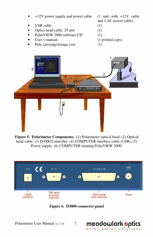
• +12V power supply and power cable (1 unit with +12V cable
and 1 AC power cable)
• USB cable (1)
• Optics head cable, 25-pin (1)
• PolarVIEW 3000 software CD (1)
• User’s manual (1 printed copy)
• Poly carrying/storage case (1)
Figure 5. Polarimeter Components. (1) Polarimeter optical head, (2) Optical
head cable, (3) D3000 Controller, (4) COMPUTER interface cable (USB), (5)
Power supply, (6) COMPUTER running PolarVIEW 3000.
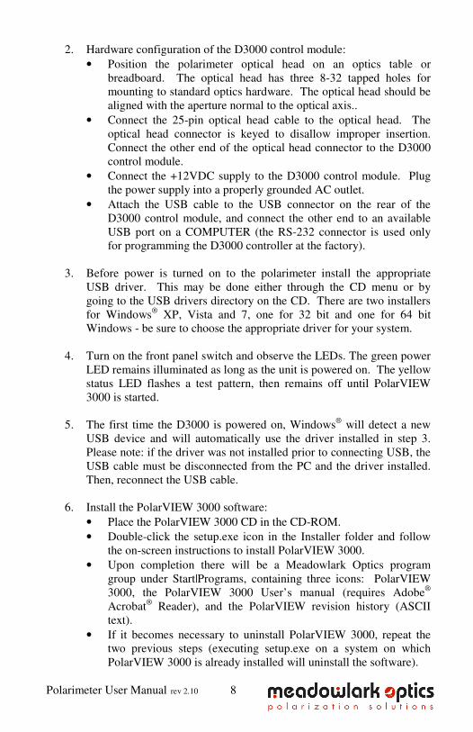
Figure 6. D3000 connector panel
Polarimeter User Manual rev 2.10 8
2. Hardware configuration of the D3000 control module:
• Position the polarimeter optical head on an optics table or
breadboard. The optical head has three 8-32 tapped holes for
mounting to standard optics hardware. The optical head should be
aligned with the aperture normal to the optical axis..
• Connect the 25-pin optical head cable to the optical head. The
optical head connector is keyed to disallow improper insertion.
Connect the other end of the optical head connector to the D3000
control module.
• Connect the +12VDC supply to the D3000 control module. Plug
the power supply into a properly grounded AC outlet.
• Attach the USB cable to the USB connector on the rear of the
D3000 control module, and connect the other end to an available
USB port on a COMPUTER (the RS-232 connector is used only
for programming the D3000 controller at the factory).
3. Before power is turned on to the polarimeter install the appropriate
USB driver. This may be done either through the CD menu or by
going to the USB drivers directory on the CD. There are two installers
for Windows® XP, Vista and 7, one for 32 bit and one for 64 bit
Windows - be sure to choose the appropriate driver for your system.
4. Turn on the front panel switch and observe the LEDs. The green power
LED remains illuminated as long as the unit is powered on. The yellow
status LED flashes a test pattern, then remains off until PolarVIEW
3000 is started.
5. The first time the D3000 is powered on, Windows® will detect a new
USB device and will automatically use the driver installed in step 3.
Please note: if the driver was not installed prior to connecting USB, the
USB cable must be disconnected from the PC and the driver installed.
Then, reconnect the USB cable.
6. Install the PolarVIEW 3000 software:
• Place the PolarVIEW 3000 CD in the CD-ROM. • Double-click the setup.exe icon in the Installer folder and follow
the on-screen instructions to install PolarVIEW 3000.
• Upon completion there will be a Meadowlark Optics program
group under Start|Programs, containing three icons: PolarVIEW
3000, the PolarVIEW 3000 User’s manual (requires Adobe®
Acrobat® Reader), and the PolarVIEW revision history (ASCII
text).
• If it becomes necessary to uninstall PolarVIEW 3000, repeat the
two previous steps (executing setup.exe on a system on which
PolarVIEW 3000 is already installed will uninstall the software).
Polarimeter User Manual rev 2.10 9
3. Using PolarVIEW 3000 Operation of the polarimeter using PolarVIEW 3000 is detailed here.
Meadowlark Optics recommends the following configuration for familiarization
with the polarimeter: Output from a laser (or other monochromatic light source)
at a calibration wavelength should be directed into the polarimeter aperture. A
polarizer and a retarder should be available to produce convenient and
predictable states of polarization (this is the configuration used in the calibration
procedure described in section 5.2).
3.1 Startup Procedure
• If the D3000 control module is not already powered on, turn on the
front panel switch and observe the LEDs. Verify the LEDs function as
described in Section 2.2.
• The optical head includes a temperature control circuit that maintains
the temperature of the liquid crystal variable retarders. Meadowlark
Optics recommends waiting 5-10 minutes for the optical head
temperature to stabilize.
• Start PolarVIEW 3000 by clicking the Windows® Start
button|Programs|Meadowlark Optics|PolarVIEW 3000.
• The user interface will immediately appear as shown in Figure 7. If
there is an error detecting the USB device (the D3000 power is not on,
cables are not fully inserted into connectors or USB drivers are not
installed) a dialog box will appear. After correcting the problem click
the “OK” button to connect to USB.

Polarimeter User Manual rev 2.10 10
3.2 PolarVIEW 3000 User Interface PolarVIEW 3000 is a user-friendly interface, Figure 7, which displays
polarization data and allows the user to perform various operations. In
addition to the controls and indicators described in the following sections,
clicking the Meadowlark Optics logo displays software and firmware
version.
Figure 7. PolarVIEW 3000 Main Screen (1) Main functions (2) Polarization data display
(3) Temperature information (4) Light levels (5) Save function (6) Display
region
3.2.1 Main Functions
• MEASURE - Begins or pauses polarization measurements.
• CALIBRATE - Displays wavelength calibration screen (section 3.3).
• EXIT - Exits PolarVIEW 3000.
• ? - Displays help.
• ACTIVE POLARIMETER - Allows switching between multiple
polarimeters connected to the same computer.
Polarimeter User Manual rev 2.10 11
3.2.2 Polarization Data Display
• STOKES PARAMETERS - Displays the four Stokes parameters.
• CALCULATED VALUES - Displays the degree of polarization
(DOP), degree of linear polarization (DOLP), degree of circular
polarization (DOCP), and phase. See large numeric tab for formulae
used to calculate these values.
• ELLIPSE PARAMETERS - Displays the ellipticity and angle.
• WAVELENGTH - Selects the wavelength for which the polarimeter
will be used.
• SMOOTH - Applies a smoothing function to the displayed
polarization data (a value of 1 produces no smoothing, increasing the
value increases the smoothing effect).
3.2.3 Temperature Information
• TEMPERATURE STATUS LED - Glows orange to indicate the
optical head temperature has not stabilized; green when the optical
head temperature is within tolerance and has stabilized. The user
should be aware that while the LED is orange, any measurements
would not be accurate.
• MEASURED TEMPERATURE - Optical head temperature, in °C.
• TEMPERATURE MONITOR - Displays the temperature screen
(section 3.4).
3.2.4 Light Levels
• INTENSITY - Indicates the maximum intensity of light incident on
each photo detector in the optical head. A value of 0.00 indicates no
light is incident on the photo detector and a value of 1.00 is the level at
which the photo detector saturates.
• DARK LEVELS - Indicates the dark level correction values for each
photo detector.
• LIGHT LEVEL LED - Glows orange if either too little or too much
light is incident on the photo detectors; glows green if the light level is
in the proper range.
• DARK MEASURE - Performs dark level correction measurement.
The LED glows orange if no dark level measurement has been
performed and green if a dark level measurement has been performed.
3.2.5 Save Function
• SAVE MODE - Selects the save mode; instantaneous mode saves all
polarization measurements to the specified text file, averaged mode
saves averaged polarization measurements to the specified text file.
• # POINTS TO SAVE - Specifies the number of polarization
measurements to be saved to the specified text file. Note: This
number can be changed while a save operation is in progress.
Polarimeter User Manual rev 2.10 12
• # AVERAGES / POINT - When in averaged mode, specifies the
number of polarization measurements to be averaged before each
averaged value is written to the specified text file. This control is
inactive when instantaneous mode is selected.
• SAVE MEASUREMENTS - Initiates the save process. When
clicked, the user is prompted for the polarization parameters to be
saved and the name of the text file in which to save the data. Note: All
save controls, with the exception of # POINTS TO SAVE, become
inactive if measurements are paused during a save operation. When
measurements are resumed the save operation resumes.
• CANCEL SAVE - Cancels a save operation that is in progress.
• SAVE PROGRESS - Indicates the progress of the save operation.
3.2.6 Display Region The display region shows one of five displays that are selectable by clicking the
tabs above the display area. Display formats are shown in Figures 8 - 12:
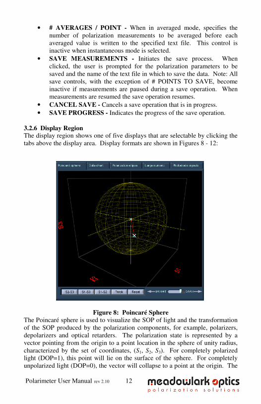
Figure 8: Poincaré Sphere
The Poincaré sphere is used to visualize the SOP of light and the transformation
of the SOP produced by the polarization components, for example, polarizers,
depolarizers and optical retarders. The polarization state is represented by a
vector pointing from the origin to a point location in the sphere of unity radius,
characterized by the set of coordinates, (S1, S2, S3). For completely polarized
light (DOP=1), this point will lie on the surface of the sphere. For completely
unpolarized light (DOP=0), the vector will collapse to a point at the origin. The
Polarimeter User Manual rev 2.10 13
north and south poles correspond to right-hand [(S1, S2, S3)=(0, 0, 1)] and left-
hand [(S1, S2, S3)=(0, 0, ,1)] circular polarization, respectively. The ellipticity
of the polarization decreases as the equator is approached and the equator
corresponds to linearly polarized light. The (S1, S2, S3) = (1, 0, 0) and (,1, 0, 0)
locations on the sphere correspond, respectively, to horizontal and vertical
polarization, whereas (S1, S2, S3)=(0, 1, 0) and (0, ,1, 0) correspond to +45°
and ,45° polarization direction angle, respectively. Notice that orthogonal
polarizations are always on opposite ends of the sphere. The Poincaré Sphere
view offers the option of selecting a projection into the equatorial plane S1-S2, or
into the longitudinal planes S1-S3 or S2-S3. It also allows rotation of the sphere
(by clicking and dragging on the graphic) and to track a polarization state path
on the sphere (TRACK button). To erase the track and return to normal mode
press RESET.
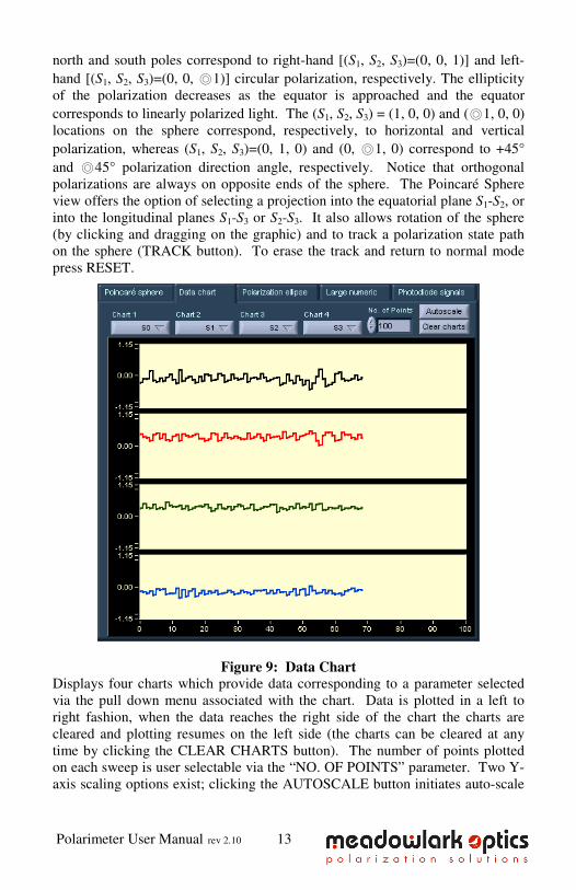
Figure 9: Data Chart Displays four charts which provide data corresponding to a parameter selected
via the pull down menu associated with the chart. Data is plotted in a left to
right fashion, when the data reaches the right side of the chart the charts are
cleared and plotting resumes on the left side (the charts can be cleared at any
time by clicking the CLEAR CHARTS button). The number of points plotted
on each sweep is user selectable via the “NO. OF POINTS” parameter. Two Y-
axis scaling options exist; clicking the AUTOSCALE button initiates auto-scale
Polarimeter User Manual rev 2.10 14
of all four charts, or the user may double click on any Y axis limit and manually
change the value.
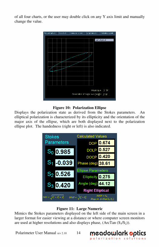
Figure 10: Polarization Ellipse Displays the polarization state as derived from the Stokes parameters. An
elliptical polarization is characterized by its ellipticity and the orientation of the
major axis of the ellipse, which are both displayed next to the polarization
ellipse plot. The handedness (right or left) is also indicated.
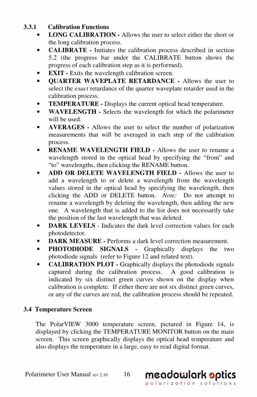
Figure 11: Large Numeric Mimics the Stokes parameters displayed on the left side of the main screen in a
larger format for easier viewing at a distance or where computer screen monitors
are used at higher resolutions and also displays phase, (ArcTan (S3/S2)).

Polarimeter User Manual rev 2.10 15
Figure 12: Photodiode signals Graphically displays the photodiode signals; the Y-axis is scaled from 0.00 (no
light) to 1.00 (saturation). The photodetector gain can be changed to account for
intensities of light incident on the photodetectors. The gain is wavelength
specific and is stored in the optical head; whenever a new wavelength is
selected, the appropriate gain is retrieved from the optical head.
3.3 Wavelength Calibration Screen The wavelength calibration screen, Figure 13, is displayed by clicking the
CALIBRATE button on the main screen. This screen is used to calibrate
the polarimeter for selected wavelengths and to make changes to the
wavelength values that are stored in the optical head.
Figure 13. PolarVIEW 3000 Wavelength Calibration Screen
Polarimeter User Manual rev 2.10 16
3.3.1 Calibration Functions
• LONG CALIBRATION - Allows the user to select either the short or
the long calibration process.
• CALIBRATE - Initiates the calibration process described in section
5.2 (the progress bar under the CALIBRATE button shows the
progress of each calibration step as it is performed).
• EXIT - Exits the wavelength calibration screen.
• QUARTER WAVEPLATE RETARDANCE - Allows the user to
select the exact retardance of the quarter waveplate retarder used in the
calibration process.
• TEMPERATURE - Displays the current optical head temperature.
• WAVELENGTH - Selects the wavelength for which the polarimeter
will be used.
• AVERAGES - Allows the user to select the number of polarization
measurements that will be averaged in each step of the calibration
process.
• RENAME WAVELENGTH FIELD - Allows the user to rename a
wavelength stored in the optical head by specifying the “from” and
“to” wavelengths, then clicking the RENAME button.
• ADD OR DELETE WAVELENGTH FIELD - Allows the user to
add a wavelength to or delete a wavelength from the wavelength
values stored in the optical head by specifying the wavelength, then
clicking the ADD or DELETE button. Note: Do not attempt to
rename a wavelength by deleting the wavelength, then adding the new
one. A wavelength that is added to the list does not necessarily take
the position of the last wavelength that was deleted.
• DARK LEVELS - Indicates the dark level correction values for each
photodetector.
• DARK MEASURE - Performs a dark level correction measurement.
• PHOTODIODE SIGNALS - Graphically displays the two
photodiode signals (refer to Figure 12 and related text).
• CALIBRATION PLOT - Graphically displays the photodiode signals
captured during the calibration process. A good calibration is
indicated by six distinct green curves shown on the display when
calibration is complete. If either there are not six distinct green curves,
or any of the curves are red, the calibration process should be repeated.
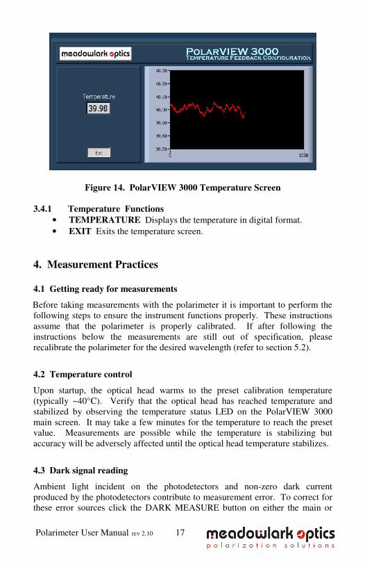
3.4 Temperature Screen
The PolarVIEW 3000 temperature screen, pictured in Figure 14, is
displayed by clicking the TEMPERATURE MONITOR button on the main
screen. This screen graphically displays the optical head temperature and
also displays the temperature in a large, easy to read digital format.
Polarimeter User Manual rev 2.10 17
Figure 14. PolarVIEW 3000 Temperature Screen
3.4.1 Temperature Functions
• TEMPERATURE Displays the temperature in digital format.
• EXIT Exits the temperature screen.
4. Measurement Practices
4.1 Getting ready for measurements
Before taking measurements with the polarimeter it is important to perform the
following steps to ensure the instrument functions properly. These instructions
assume that the polarimeter is properly calibrated. If after following the
instructions below the measurements are still out of specification, please
recalibrate the polarimeter for the desired wavelength (refer to section 5.2).
4.2 Temperature control
Upon startup, the optical head warms to the preset calibration temperature
(typically ~40°C). Verify that the optical head has reached temperature and
stabilized by observing the temperature status LED on the PolarVIEW 3000
main screen. It may take a few minutes for the temperature to reach the preset
value. Measurements are possible while the temperature is stabilizing but
accuracy will be adversely affected until the optical head temperature stabilizes.
4.3 Dark signal reading
Ambient light incident on the photodetectors and non-zero dark current
produced by the photodetectors contribute to measurement error. To correct for
these error sources click the DARK MEASURE button on either the main or
Polarimeter User Manual rev 2.10 18
wavelength calibration screen. A pop-up window will prompt the user to block
the beam. Block it as far away from the optical head aperture as convenient and
click OK. On the following window, click to record the measured dark signal or
repeat the measurement.
4.4 Photodiode gain control
Photodiode output signals will vary depending on the intensity of light incident
on the photodiodes. The photodiode gain must be set so that “low light” and
“saturation” conditions do not exist. To set the gain value, go to the main screen
and click the ‘Photodiode signals’ tab. Select a value that produces plotted
signals that max out at about 0.7 or 0.8 on the Y axis (refer to Figure 12 and
related text). The gain should be adjusted every time the external light source
varies.
4.5 Wavelength selection
The SOP measurement is wavelength dependent. The wavelength selection
control reads the wavelengths stored in the optical head and allows the user to
select the desired wavelength.
4.6 Start measurement and warm-up period
To start measuring, click the MEASURE button on the main screen. (Note:
Verify the temperature stabilized LED is glowing green to ensure maximum
accuracy).
4.7 Smoothing
PolarVIEW 3000 offers a smoothing function that reduces jitter on the displayed
polarization data. This function is especially useful for noisy signals where the
polarization state fluctuates. Enter the smoothing value via the smoothing
control on the main screen (a value of 1 produces no smoothing, increasing the
value increases the smoothing effect).
4.8 Sampling and recording to a file
Polarization measurement values may be saved to a text file by clicking the
SAVE MEASUREMENTS button on the main screen. After clicking the
button, dialog boxes will prompt for the parameters to be saved and the file in
which to store data. If an existing filename is entered, new data will be
appended to the existing file. In instantaneous mode if smoothing is active,
smoothed polarization values are written to the data file. In averaged mode
smoothed values are averaged and then written to the file (see section 3.2.5).
Data files generated by PolarVIEW 3000 are tab-delimited ASCII text format,
and are readily compatible with common spreadsheet and analysis software.
When Save Measurements is activated, data is written to an output file in the

Polarimeter User Manual rev 2.10 19
following format:
time S0 S1 S2 S3 DOP DOLP DOCP Phase e eta temp
Where
time = elapsed time in HH:MM:SS.msec since the save was started.
S0, S1, S2, S3 = the four Stokes parameters.
DOP = Degree of Polarization.
DOLP = Degree of Linear Polarization.
DOCP = Degree of Circular Polarization.
Phase = Phase of light. (ArcTan (S3/S2)). e = Polarization ellipticity (0=linear, 1=circular).
eta = Angle of the polarization ellipse major axis (±90°).
temp = Temperature of polarimeter optics head.
Note: This example assumes all parameters were selected to be saved.
Different combinations can be selected via the Save Measurements dialog box.
Polarimeter User Manual rev 2.10 20
5. Laboratory Considerations
5.1 Optical alignment
It is important to properly align the polarimeter optical head. A misaligned
optical head results in insufficient light on the photodetectors causing a
weak signal. Furthermore, the distance light travels through a birefringent
medium determines the amount of retardance. Therefore angular
misalignment of the optical head changes angle of incidence of light on the
LC retarders, thereby changing the path length through the liquid crystal.
This causes error in the detected ellipticity. While proper alignment is
important, it is not difficult to achieve. The configuration of the aperture on
the front of the optical head facilitates alignment; light that is sufficiently
off-axis to cause an error in the retardance measurement will not land on the
photodetectors. The most straightforward alignment method is:
• Position the optical head roughly so that the light to be measured is
normal to the aperture.
• Start PolarVIEW 3000, click the ‘Photodiode signals’ button on
the main screen and observe the photodiode signals plotted on the
screen.
• Adjust the fine positioning of the optical head until the photodiode
signals are maximized.
• Tighten the mounting apparatus to secure the optical head.
If a more rigorous alignment is desired, the following technique is offered:
• Make sure the beam to be measured is collimated.
• Pick a surface plane (normal to the beam) within the laser beam
path.
• Measure the approximate diameter of the laser beam at this plane.
Place the polarimeter at a distance from this plane of at least 60
times the measured diameter.
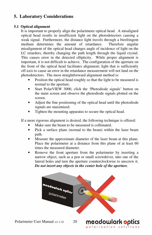
• Remove the front aperture from the polarimeter by inserting a
narrow object, such as a pen or small screwdriver, into one of the
lateral holes and turn the aperture counterclockwise to unscrew it.
Do not insert any objects in the center hole of the aperture.
Polarimeter User Manual rev 2.10 21
• With the aperture removed, locate the strongest retro-reflected
beam.
• Rotate and position the polarimeter so that the reflected beam
overlaps the incident beam.
• Be aware that some lasers will not be polarization stable if a
portion of the beam is precisely retro-reflected back into the output
coupler. If polarization or power variations are noticed, slightly
misalign the beam to avoid optical feedback.
• Tighten the mounting fixtures and reinsert the front aperture,
making sure you don’t lose your alignment.
5.2. Calibration The polarimeter comes pre-calibrated at up to twelve wavelengths. Due to
changes in environmental conditions and laboratory configurations, recalibration
by the user upon delivery and frequently thereafter is recommended. A basic
knowledge of polarization optics is helpful for the calibration process.
The calibration procedure requires providing the polarimeter with six input
standard States of Polarization (SOP), those being horizontal, vertical, +45°, -
45°, right-hand circular (RHC) and left-hand circular (LHC). Calibration is a
function of the PolarVIEW 3000 software; the six standard states of polarization
will be requested as the procedural steps are completed. The following
procedure describes how to produce these states using a linear polarizer and a
quarter-wave retarder, as shown in Figure 15. Meadowlark Optics now offers a
calibration device that consists of a linear polarizer and a quarter-wave retarder,
both in holders that kinematically mount to a platform to produce desired states
of polarization with trivial effort. Please contact Meadowlark Optics for more
information.
Two calibration options exist; a short calibration and a long calibration. The
short calibration consists of six steps while the long calibration consists of 10
steps. Either calibration procedure will give sterling results, however, for the
user that desires maximum accuracy the long calibration procedure is intended
to give slightly better results. For either option, best results will be obtained if
the photodiode gain is set to produce photodiode curves that max out at about
0.7 or 0.8.
Referring to the diagram in Figure 15, the polarizer (with the quarter-wave
retarder removed) produces linear polarization states. The angle of the linear
state is determined by the rotational orientation of the polarizer. Therefore, the
polarizer in Figure 15 should be mounted such that it can be rotated precisely
(within ~5 arc minutes) to the desired angles. Using the quarter-wave retarder
with the polarizer produces circular states. The retarder must be positioned such
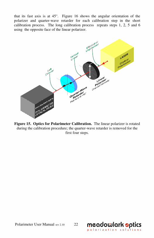
Polarimeter User Manual rev 2.10 22
that its fast axis is at 45°. Figure 16 shows the angular orientation of the
polarizer and quarter-wave retarder for each calibration step in the short
calibration process. The long calibration process repeats steps 1, 2, 5 and 6
using the opposite face of the linear polarizer.
Figure 15. Optics for Polarimeter Calibration. The linear polarizer is rotated
during the calibration procedure; the quarter-wave retarder is removed for the
first four steps.
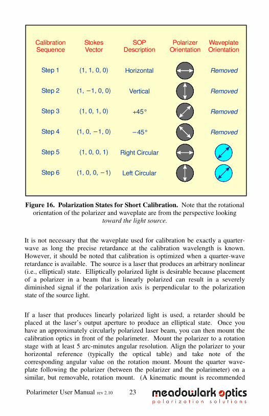
Polarimeter User Manual rev 2.10 23
Figure 16. Polarization States for Short Calibration. Note that the rotational
orientation of the polarizer and waveplate are from the perspective looking
toward the light source.
It is not necessary that the waveplate used for calibration be exactly a quarter-
wave as long the precise retardance at the calibration wavelength is known.
However, it should be noted that calibration is optimized when a quarter-wave
retardance is available. The source is a laser that produces an arbitrary nonlinear
(i.e., elliptical) state. Elliptically polarized light is desirable because placement
of a polarizer in a beam that is linearly polarized can result in a severely
diminished signal if the polarization axis is perpendicular to the polarization
state of the source light.
If a laser that produces linearly polarized light is used, a retarder should be
placed at the laser’s output aperture to produce an elliptical state. Once you
have an approximately circularly polarized laser beam, you can then mount the
calibration optics in front of the polarimeter. Mount the polarizer to a rotation
stage with at least 5 arc-minutes angular resolution. Align the polarizer to your
horizontal reference (typically the optical table) and take note of the
corresponding angular value on the rotation mount. Mount the quarter wave-
plate following the polarizer (between the polarizer and the polarimeter) on a
similar, but removable, rotation mount. (A kinematic mount is recommended
(1, 1, 0, 0) Horizontal RemovedStep 1
(1, 1, 0, 0)−
(1, 0, 1, 0)
(1, 0, 1, 0)−
(1, 0, 0, 1)
(1, 0, 0, 1)−
Vertical Removed
+45° Removed
−45° Removed
Right Circular
Left Circular
Step 2
Step 3
Step 4
Step 5
Step 6
StokesVector
SOPDescription
PolarizerOrientation
WaveplateOrientation
CalibrationSequence
Polarimeter User Manual rev 2.10 24
for mounting the wave-plate.) Carefully align the wave-plate axis to be at 45o
with respect to the polarizer axis when this latter is aligned to the horizontal
reference. (At this position the polarizer-wave-plate set will consist of an
optical isolator. Thus, one reliable way to set or verify this 45o alignment
between the wave-plate and the polarizer is by placing a retro-reflecting mirror
behind the wave-plate and picking up the reflected beam, after it crosses the
polarizer, with a beam-splitter and directing it to a detector. Rotate the wave
plate: the intensity of the retro-reflected light will be a minimum when the plate
is at 45o degrees to the polarizer.) Once the wave-plate is aligned, lock it to that
angular position as it won’t need to be rotated during calibration.
To start the calibration process, ensure the polarimeter is aligned as described
above. Perform a dark signal measurement by covering the beam as far away
from the polarimeter as convenient, then clicking the DARK MEASURE button.
Follow the prompts to record the dark value. Ensure the appropriate wavelength
is selected and the quarter wave-plate retardance is set to the correct value. Set
the number of measurements to be averaged for each calibration SOP to the
desired value and select the calibration procedure to be performed. Initiate the
calibration process by clicking the CALIBRATE button. Follow the
instructions detailed for each calibration step, paying careful attention to the
diagrams and the FACE A/FACE B orientation of the polarizer (polarizer faces
will be clearly marked if the polarizer was purchased from Meadowlark Optics
as part of a calibration set).
When the calibration process is complete the calibration plot should display six
distinct green curves. If any curves are red the maximum amplitude of that
curve was either too high or too low and the photodiode gain should be adjusted
before recalibrating. If there are less than six distinct curves then very likely
one or more of the calibration steps was not performed properly and the user
should recalibrate. The user may then choose to save the calibration data or
cancel without saving. Measurements may then be resumed by clicking the
EXIT button to return to the main screen.
Polarimeter User Manual rev 2.10 25
6. User Development with LabVIEW™ VI’s Provided by
Meadowlark Optics, Inc.
Several VI’s are included in a library file on the PixelDRIVE 3000 CD. They
can be found in <drive letter>:\LabVIEW\ directory. LabVIEW™ VI’s that
interface with the D3128 are:
• Meadowlark Polarimeter User Example.VI
• Meadowlark Polarimeter User VI’s.LLB
o Meadowlark Polarimetry Output.VI
o Meadowlark Initialize Polarimeter.VI
o Meadowlark Read Polarimeter.VI
o Meadowlark Shutdown Polarimeter.VI
o Various helper VI’s
The user development directory includes a LabVIEW™ library file containing
fundamental VI’s and examples that implement them in rudimentary programs
that read polarimetry data out of the polarimeter. The LabVIEW™ back panel
of the polarimeter example VI has been made accessible to our customers to
facilitate independent development. Developers are encouraged to open and
examine the example VI diagram screen. Please note that the LabVIEW™
development suite (version 6.1 or greater) from National Instruments is required
to use the included VI’s, and Meadowlark Optics, Inc. does not provide this
development package with PolarVIEW 3000. It is assumed that the customer
has experience programming in LabVIEW™ and understands good
programming practices. Meadowlark Optics, Inc. cannot offer customer support
for LabVIEW™ application development. If a developed or modified
LabVIEW™ application is to be distributed in any way, please contact
Meadowlark Optics for licensing and copyright details.
7. General Specifications Maximum absolute Degree Of Polarization error: < 1%
Wavelength Range for Calibration Accuracy: ± 3 nm
Measurement Frequency: 10Hz (USB interface)
Resolution: 0.001 of a Stokes
Parameter
Maximum Operating Temperature: 35°C
Optical Head Dimensions (inches): 2.83 × 1.75 × 1.75
Minimum Optical Power to maintain accuracy: 10 µW
(Sensitivity can be increased by special request)
Driver Power Requirements: 115V/220V (±10%)
5 W Max.
Polarimeter User Manual rev 2.10 26
Appendix A: Frequently Asked Questions
Q: Why is the controller not working?
A: Check that the power supply is plugged in, front panel switch is on and the
green power light is steady. Check the status of the USB interface under
Windows® Device Manager. Occasionally it helps to reboot the controller;
turn off the controller, wait a few seconds, then turn it back on.
Q: I started the PolarVIEW 3000 software and then turned on the D3000
controller, now the software is behaving erratically. What is happening?
A: The D3000 controller must be turned on and have completed its power-on
self-test before starting the PolarVIEW 3000 software.
Q: How do I uninstall the PolarVIEW 3000 software?
A: Use the Add/Remove Programs option in the Windows® control panel.
Q: Are there Apple, Linux, OS/2, or UNIX versions of PolarVIEW 3000? Can
I use PolarVIEW 3000 on a COMPUTER running MS-DOS®, Windows
®
3.1, Windows® 95, Windows
® 98, or Windows
® NT?
A: No. PolarVIEW 3000 runs under the 98SE, ME, 2000, and XP versions of
Microsoft® Windows
® only.
Q: What is the purpose of the SYNC connector on the front panel?
A: A pulse is produced on the SYNC connector each time the D3000 controller
has finished gathering a set of photodetector samples. This signal can be
used to synchronize external devices to the D3000.
Q: What is the default optical head temperature value?
A: The optical head temperature will be maintained at ~40°C.
Q: Why does the front panel status LED blink when running PolarVIEW 3000?
A: The front panel status LED blinks to indicate that polarization data is being
transferred from the D3000 controller to PolarVIEW 3000.
Q: Is there any significance to the blink rate?
A: In a normally operating system the front panel status LED should blink at
10 Hz.
Q: Why might the front panel status LED blink in an erratic fashion?
A: If polarization data is not being transferred at a 10 Hz rate it will be
reflected by the blink rate of the front panel status LED. Normal causes
would be a slow COMPUTER, excessive network activity or applications
(e.g., anti-virus software) running on the COMPUTER that require
excessive processor bandwidth.
Polarimeter User Manual rev 2.10 27
Q: Is it a problem if the polarimeter is running at less than 10 Hz?
A: No. PolarVIEW 3000 still displays accurate data but the update rate will be
less than 10Hz.
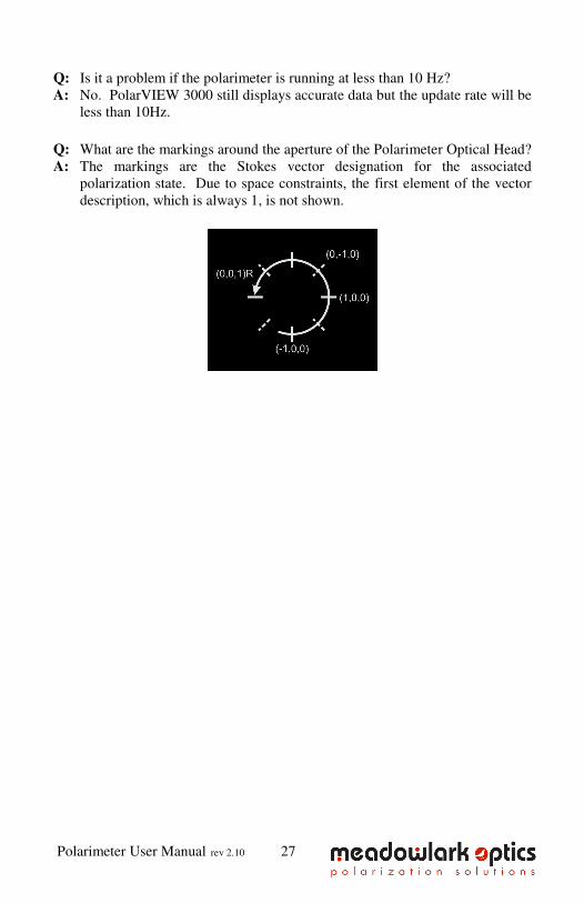
Q: What are the markings around the aperture of the Polarimeter Optical Head?
A: The markings are the Stokes vector designation for the associated
polarization state. Due to space constraints, the first element of the vector
description, which is always 1, is not shown.
Polarimeter User Manual rev 2.10 28
Appendix B: Firmware Updater
The D3000 internal firmware can be reprogrammed by the user when new versions are
released by Meadowlark Optics. Update is accomplished by using the firmware updater
program included on the PolarVIEW CD. In order to use the firmware updater program
the D3000 must be powered on and connected to an available USB port on the host
computer.
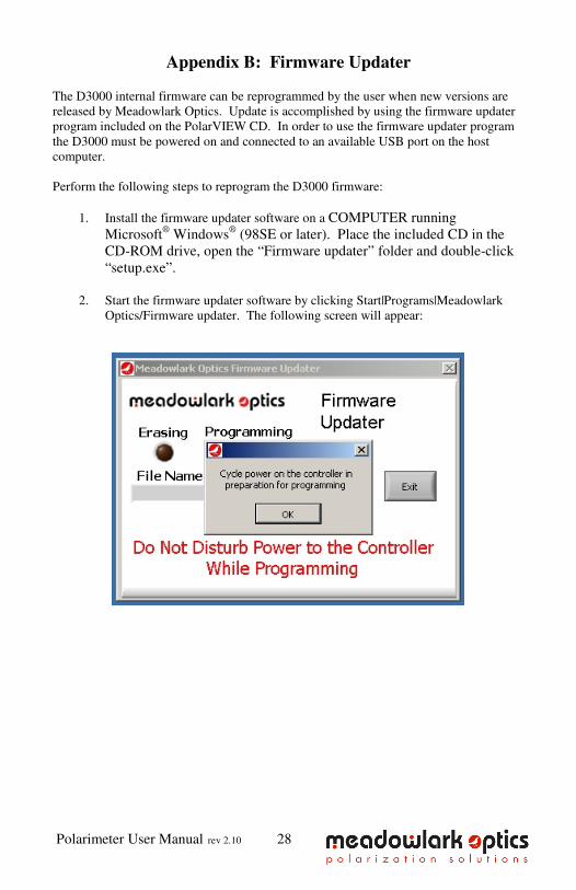
Perform the following steps to reprogram the D3000 firmware:
1. Install the firmware updater software on a COMPUTER running
Microsoft® Windows
® (98SE or later). Place the included CD in the
CD-ROM drive, open the “Firmware updater” folder and double-click
“setup.exe”.
2. Start the firmware updater software by clicking Start|Programs|Meadowlark
Optics/Firmware updater. The following screen will appear:

Polarimeter User Manual rev 2.10 29
3. Cycle power on the D3000 controller to ensure the USB connection is properly
made. Wait until the front panel status LED is done flashing before clicking
OK. If the power is not cycled or the OK button is clicked before the front
panel status LED is done flashing, the following error will be displayed. If this
error appears, close the firmware updater program and re-run it.
4. The following screen will appear after the USB connection is made.

Polarimeter User Manual rev 2.10 30
5. Choose the new hex file and click “OK”. The program will check if the new
firmware file is valid for the D3000, if not, the following error screen will
appear. At this point the user may elect to choose a different file or go ahead
and program the D3000 with the chosen file. Extreme caution should be
exercised when deciding whether to program the D3000 with a file that may
not be compatible. If there are questions about choosing the appropriate file
please contact Meadowlark Optics at 303-833-4333.
6. After the hex file is loaded and passes the validity tests, the ready screen
appears as below (Code Size shows the size of the firmware code and is present
only for troubleshooting). Click the Program button to reprogram the D3000
firmware. If a final check is desired before reprogramming firmware the
Meadowlark Optics logo may be clicked to display a screen (shown below)
showing the old and new firmware versions.

Polarimeter User Manual rev 2.10 31
7. As the firmware is being erased and reprogrammed the status will be displayed
as shown below. DO NOT disturb power to the D3000 while it is erasing or
reprogramming, if memory is corrupted it will be required to return the unit to
Meadowlark Optics for reprogramming.
Polarimeter User Manual rev 2.10 32
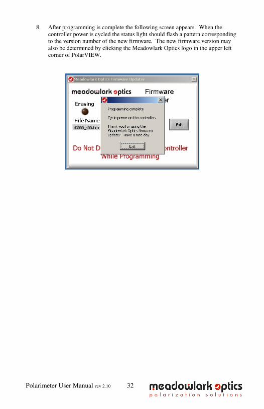
8. After programming is complete the following screen appears. When the
controller power is cycled the status light should flash a pattern corresponding
to the version number of the new firmware. The new firmware version may
also be determined by clicking the Meadowlark Optics logo in the upper left
corner of PolarVIEW.
Appendix C: Software Licensing
IMPORTANT. CAREFULLY READ THE TERMS AND CONDITIONS OF THIS LICENSE AGREEMENT BEFORE USING THIS SOFTWARE.
This Meadowlark Optics, Inc. License Agreement is a legal agreement
between you (“Licensee”) and Meadowlark Optics, Inc. (“Licensor”) for the
enclosed computer software, and any associated media, printed materials
and online or electronic documentation (“Software”). By installing or
otherwise using the Software Product, you agree to be bound by the terms of this License Agreement. If you do not agree to the terms of this License
Agreement, do not use or install the Software Product, you may however
return it to your place of purchase for a refund.
SOFTWARE LICENSE AGREEMENT This Software License Agreement (“Agreement”) is entered into
between Meadowlark Optics, Inc (“Licensor”) and you as Licensee, (Licensee”).
1. Definitions a. Software. The term “Software” shall mean the enclosed computer
software, and any associated media, printed materials and online or electronic
documentation .. The term “Software” includes any corrections, bugs, fixes,
enhancements, updates or other modifications, including custom modifications,
to such computer programs.
2. License a. Grant of License. Licensor grants Licensee, pursuant to the terms
and conditions of this Agreement, a limited, revocable, non-exclusive, non-
transferable license to use the Software, which has been built with National
Instruments LabVIEW™ Application Builder.
b. Restrictions on Use. Licensee agrees to use the Software only for
Licensee’s own business. Licensee shall not: (i) permit any parent, subsidiaries,
affiliated entities or third parties to use the Software; (ii) process or permit to be
processed the data of any other party, (iii) use the Software in the operation of a
service bureau, or (iv) allow access to the Software through any terminals
located outside of Licensee’s Site.
c. Copies. Licensee, solely to enable it to use the Software, may
make one archival copy of the Software computer program, provided that the
copy shall include Licensor’s copyright and any other propriety notices. The
Software delivered by Licensor to Licensee and the archival copy shall be stored
at Licensee’s Site.
d. Modifications, Reverse Engineering. Licensee agrees that only
Licensor shall have the right to alter, maintain, enhance or otherwise modify the
Software. Licensee shall not disassemble, decompile or reverse engineer the
Software.
e. Material Terms and Conditions. Licensee specifically agrees that
the terms and Conditions of this Section 2 are material and that failure of
Licensee to comply with these terms and conditions shall constitute sufficient
cause to terminate this Agreement.
3. Data Conversion, Support a. Data Conversion. Licensee shall be solely responsible for data
conversion, data entry and verification of data.
b. Support. Licensor may provide Licensee with support services
related to the Software. Use of Support services is governed by the Licensor
policies and programs described in the Service Level Agreement. Any
supplemental software code, modifications or enhancements provided to you as
part of the Support service shall be considered part of the Software and subject
to the terms of this License Agreement.
4. Ownership a. Title. Licensee and Licensor agree that Licensor owns all
proprietary rights, including patent, copyright, trade secret, trademark and other
proprietary rights, in and to the Software and any bug fixes, enhancements,
updates or other modifications, including custom modifications, to the Software,
whether made by Licensor or any third party.
b. Transfers. Under no circumstances shall Licensee sell, license,
publish display, distribute or otherwise transfer to a third party the Software or
any copy thereof, in whole or in part, without Licensor’s prior written consent.
5. Limited Warranty; Support Services a. Scope of Warranty. Licensor warrants for a period of one year
from the date of receipt of the Software against faulty workmanship or the use of
defective materials and that such Software will conform to Licensor’s
accompanying written specifications. This limited warranty shall be void in the
event of failure from accident, abuse or misapplication.
b. Disclaimer of Any Other Warranty. THE LIMITED WARRANTY
SET FORTH IN SUBSECTION 5.a IS IN LIEU OF ALL OTHER
WARRANTIES, INCLUDING, BUT NOT LIMITED TO, THE IMPLIED
WARRANTIES OF MERCHANTABILITY AND FITNESS FOR A
PARTICULAR PURPOSE.
6. No Consequential Damages
NEITHER PARTY SHALL BE LIABLE TO THE OTHER FOR
INDIRECT, SPECIAL, INCIDENTAL, EXEMPLARY OR
CONSEQUENTIAL DAMAGES (INCLUDING, WITHOUT LIMITATION, LOST PROFITS) RELATED TO THIS AGREEMENT
OR RESULTING FROM LICENSEE’S USE OR INABILITY TO USE
THE SOFTWARE, ARISING FROM ANY CAUSE OF ACTION
WHATSOEVER, INCLUDING CONTRACT, WARRANTY, STRICT
LIABILITY OR NEGLIGENCE, EVEN IF THAT PARTY HAS BEEN ADVISED OF THE POSSIBILITY OF SUCH DAMAGES.
7. Limitation on Recovery
Under no circumstances shall the liability of Licensor to Licensee
exceed the amounts paid by Licensee to Licensor under this Agreement.
8. Indemnity Licensor shall indemnify and hold harmless Licensee from and against
any claims based on infringement of any United States copyright or patent by
the Software. Licensee agrees to cooperate fully with Licensor during such
proceedings. Licensor shall defend and settle at its sole expense all proceedings
arising out of the foregoing. In the event of such infringement, Licensor may
replace, in whole or in part, the Software with a substantially equivalent
computer program or modify the Software to avoid the infringement.
9. Term and Termination a. Term. This license agreement is effective from the date of receipt
of this agreement and shall remain in full force until terminated. Without
prejudice to any other right, Licensor may terminate this agreement if you fail to
comply with any of the terms and conditions of this license agreement.
b. Procedure upon Termination. Within ten (10) days after
termination of this Agreement, Licensee will return to Licensor, at Licensee’s
expense, the Software and all copies thereof, delete or destroy all other copies of
the Software, and deliver to Licensor a certification, signed by an officer of
Licensee, that the Software has been returned, all copies deleted or destroyed,
and its use discontinued.
10. Force Majeure If performance hereunder (other than payment) is interfered with by
any condition beyond a party’s reasonable control, including any Act of God,
the affected party shall be excused from such performance to the extent of such
condition. However, if a force majeure detrimentally affects a party’s
performance of a material obligation hereunder for 14 days or more, the other
party can terminate this Agreement.
11. Mediation, Arbitration The parties shall endeavor to resolve any dispute by mediation in
Boulder, CO under the CPR Mediation Procedure. If the parties have not
resolved this matter within 45 days from the selection of a mediator, the parties
shall settle any controversy arising out of this Agreement) by arbitration to be
held in Boulder, Colorado, in accordance with the rules of the American
Arbitration Association. A single arbitrator shall be agree upon by the parties,
or, if the parties cannot agree upon an arbitrator within thirty (30) days, then the
parties agree that a single arbitrator shall be appointed by the American
Arbitration Association. The arbitrator will apply the substantive law of the
State of Colorado. The arbitrator may award attorney’s fees and costs as part of
the award. The award of the arbitrator shall be binding and may be entered as a
judgment in any court of competent jurisdiction.
12. Notices Any notice under this Agreement will be in writing and delivered by
personal delivery, overnight courier, confirmed facsimile, confirmed e-mail, or
certified or registered mail, return receipt requested, and will be deemed given
upon personal delivery, 1 day after deposit with an overnight courier, 5 days
after deposit in the mail, or upon confirmation of receipt of facsimile or email.
Notices will be sent to a party at its address set forth at the end of this
Agreement, or such other address as a party may specify in writing pursuant to
this Section.
13. Entire Agreement; Amendment; Waiver This Agreement sets forth the entire understanding and agreement of
the parties, and supersedes any and all oral or written agreements or
understandings between the parties, as to the subject matter of the Agreement.
This Agreement may be changed only by a writing signed by both parties. The
waiver of a breach of any provision of this Agreement will not operate or be
interpreted as a waiver of any other or subsequent breach.
14. Severability; Headings If any provision herein is held to be invalid or unenforceable for any
reason, the remaining provisions will continue in full force without being
impaired or invalidated in any way. The parties agree to replace any invalid
provision with a valid provision that most closely approximates the intent and
economic effect of the invalid provision. Headings are for reference purposes
only and in no way define, limit, construe or describe the scope or extent of such
section.
15. Governing Law This Agreement will be governed and construed in accordance with the
laws of the State of Colorado without giving effect to conflict of laws principles.
Both parties submit to personal jurisdiction in Colorado.
Trademarks National Instruments
® and LabVIEW
® are trademarks of National Instruments
Corporation. Microsoft
® and Windows
® are trademarks of Microsoft Corporation.
Adobe® and Acrobat
® are trademarks of Adobe Systems, Inc.


5964 Iris Parkway
PO Box 1000 (US Mail)
Frederick, CO 80530
(303) 833-4333
www.meadowlark.com


