15 Liquid Film Thickness in Micro-Scale Two-Phase Flow Naoki Shikazono and Youngbae Han The University of Tokyo Japan 1. Introduction Liquid film formed between confined vapor bubble and tube wall in micro-scale two phase flow plays an important role in heat exchangers and chemical reactors, since local heat and mass transfer is effectively enhanced at the thin liquid film region (Taha and Cui, 2006). However, characteristics of the liquid film in micro-scale two phase flows are not fully understood, and thus designing two-phase flow systems still remains as a difficult task. It is reported that the thickness of the liquid film is one of the most important parameters for predicting two phase flow heat transfer in micro tubes, see Thome et al., 2004; Kenning et al., 2006; Qu and Mudawar, 2004; Saitoh et al., 2007. For example, in the three zone evaporation model proposed by Thome et al. (2004), initial liquid film thickness is one of the three unknown parameters which must be given from experimental studies. Many researches have been conducted to investigate the characteristics of liquid film both experimentally and theoretically. Taylor (1961) experimentally obtained mean liquid film thickness in a slug flow by measuring the difference between bubble velocity and mean velocity. Highly viscous fluids, i.e. glycerol, syrup-water mixture and lubricating oil, were used so that wide capillary number range could be covered. It was found that the ratio of bubble velocity to mean velocity approaches an asymptotic value of 0.55. This asymptotic value was re-evaluated by Cox (1964), which was reported to be 0.60. Schwartz et al. (1986) investigated the effect of bubble length on the liquid film thickness using the same method as Taylor (1961). It was reported that longer bubbles move faster than shorter ones. Bretherton (1961) proposed an analytical theory for the bubble profile and axial pressure drop across the bubble using lubrication equations. Assuming small capillary number, it is shown that the dimensionless liquid film thickness can be scaled by an exponential function of capillary number, Ca 2/3 . Liquid film thickness can also be measured from the temperature change of the channel wall under the assumption that the whole liquid film on the wall evaporates and the heat is wholly consumed by the evaporation of the liquid film. Cooper (1969) measured liquid film thickness with this method and investigated the bubble growth in nucleate pool boiling. Moriyama and Inoue (1996) measured liquid film thickness during a bubble expansion in a narrow gap. It was reported that liquid film thickness is affected by the viscous boundary layer in the liquid slug when acceleration becomes large. Their experimental data was correlated in terms of capillary number, Bond number and dimensionless boundary layer thickness. Heil (2001) numerically investigated the inertial www.intechopen.com
Transcript
15
Liquid Film Thickness in Micro-Scale Two-Phase Flow
Naoki Shikazono and Youngbae Han The University of Tokyo
Japan
1. Introduction
Liquid film formed between confined vapor bubble and tube wall in micro-scale two phase
flow plays an important role in heat exchangers and chemical reactors, since local heat and
mass transfer is effectively enhanced at the thin liquid film region (Taha and Cui, 2006).
However, characteristics of the liquid film in micro-scale two phase flows are not fully
understood, and thus designing two-phase flow systems still remains as a difficult task. It is
reported that the thickness of the liquid film is one of the most important parameters for
predicting two phase flow heat transfer in micro tubes, see Thome et al., 2004; Kenning et
al., 2006; Qu and Mudawar, 2004; Saitoh et al., 2007. For example, in the three zone
evaporation model proposed by Thome et al. (2004), initial liquid film thickness is one of the
three unknown parameters which must be given from experimental studies.
Many researches have been conducted to investigate the characteristics of liquid film both
experimentally and theoretically. Taylor (1961) experimentally obtained mean liquid film
thickness in a slug flow by measuring the difference between bubble velocity and mean
velocity. Highly viscous fluids, i.e. glycerol, syrup-water mixture and lubricating oil, were
used so that wide capillary number range could be covered. It was found that the ratio of
bubble velocity to mean velocity approaches an asymptotic value of 0.55. This asymptotic
value was re-evaluated by Cox (1964), which was reported to be 0.60. Schwartz et al. (1986)
investigated the effect of bubble length on the liquid film thickness using the same method
as Taylor (1961). It was reported that longer bubbles move faster than shorter ones.
Bretherton (1961) proposed an analytical theory for the bubble profile and axial pressure
drop across the bubble using lubrication equations. Assuming small capillary number, it is
shown that the dimensionless liquid film thickness can be scaled by an exponential function
of capillary number, Ca2/3. Liquid film thickness can also be measured from the temperature
change of the channel wall under the assumption that the whole liquid film on the wall
evaporates and the heat is wholly consumed by the evaporation of the liquid film. Cooper
(1969) measured liquid film thickness with this method and investigated the bubble growth
in nucleate pool boiling. Moriyama and Inoue (1996) measured liquid film thickness during
a bubble expansion in a narrow gap. It was reported that liquid film thickness is affected by
the viscous boundary layer in the liquid slug when acceleration becomes large. Their
experimental data was correlated in terms of capillary number, Bond number and
dimensionless boundary layer thickness. Heil (2001) numerically investigated the inertial
www.intechopen.com
Two Phase Flow, Phase Change and Numerical Modeling
342
force effect on the liquid film thickness. It is shown that the liquid film thickness and the
film thickness of fluids with relatively low surface tension. It was found that the liquid film
thickness deviates from the Taylor's data at relatively high capillary numbers. Visco-inertia
regime, where the effect of inertial force on the liquid film thickness becomes significant,
was demonstrated. Kreutzer et al. (2005) studied liquid film thickness and pressure drop in
a micro tube both numerically and experimentally. Predicted liquid film thickness showed
almost the same trend as reported by Heil (2001).
Several optical methods have been applied for liquid film thickness measurement, e.g.
optical interface detection, laser extinction, total light reflection and laser confocal
displacement etc. Ursenbacher et al. (2004) developed a new optical method to detect
instantaneous vapor-liquid interface. Interface of stratified two-phase flow in a 13.6 mm
inner diameter tube was detected in their experiment. Utaka et al. (2007) measured liquid
film thickness formed in narrow gap channels with laser extinction method. Liquid film
thickness from 2 to 30 µm was measured in 0.5, 0.3 and 0.15 mm gap channels. It was
concluded that the boiling process were dominated by two characteristic periods, i.e., micro-
layer dominant and liquid saturated periods. Hurlburt & Newell (1996) developed a device
which can measure liquid film thickness from total light reflection. Using the same method,
Shedd & Newell (2004) measured liquid film thickness of air/water two-phase flow in
round, square and triangular tubes. Other measurement techniques, e.g. acoustical, electrical
and nucleonic methods are summarized comprehensively in the review paper of Tibirica et
al. (2010). Although many experiments have been carried out to measure liquid film thickness, quantitative data of local and instantaneous liquid film thicknesses are still limited. To develop precise heat transfer models for micro-scale two phase flows, it is crucial to predict liquid film thickness accurately around the confined bubble. In the present study, local and instantaneous liquid film thicknesses are measured directly with laser confocal displacement meter. Series of experiments is conducted to investigate the effects of parameters such as viscosity, surface tension and inertial forces, cross sectional shapes on the formation of liquid film in micro-scale two phase flow. In addition, under flow boiling conditions, the bubble velocity is not constant but accelerated. Acceleration may affect the balance between viscous, surface tension and inertia forces in the momentum equation. It is thus very important to consider this acceleration effect on the liquid film thickness (Kenning et al., 2006). In the present study, liquid film thickness is measured systematically using laser confocal method, and simple scaling analyses are conducted to obtain predictive correlations for the initial liquid film thickness.
2. Experimental setup and procedures
In this section, experimental setup and procedures are described. Refer to the original papers by the authors for details (Han & Shikazono, 2009a, 2009b, 2010 and Han et al. 2011).
2.1 Test section configuration
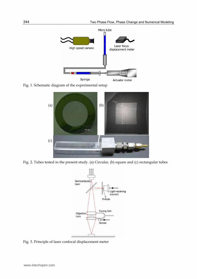
Figure 1 shows the schematic diagram of the experimental setup. Circular tubes made of
Pyrex glass with inner diameters of Dh ≈ 0.3, 0.5, 0.7, 1.0 and 1.3 mm, square quartz tubes
www.intechopen.com
Liquid Film Thickness in Micro-Scale Two-Phase Flow
343
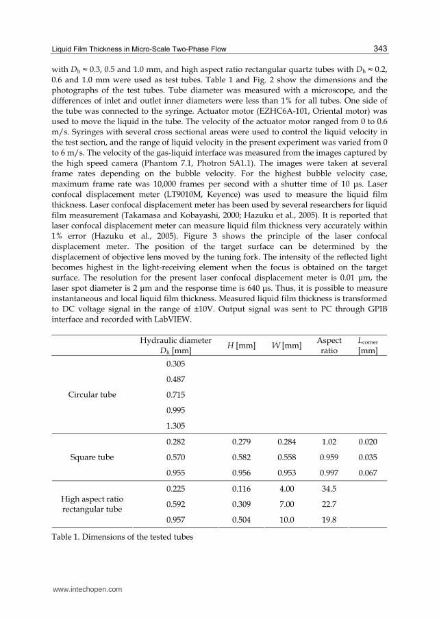
with Dh ≈ 0.3, 0.5 and 1.0 mm, and high aspect ratio rectangular quartz tubes with Dh ≈ 0.2,
0.6 and 1.0 mm were used as test tubes. Table 1 and Fig. 2 show the dimensions and the
photographs of the test tubes. Tube diameter was measured with a microscope, and the
differences of inlet and outlet inner diameters were less than 1% for all tubes. One side of
the tube was connected to the syringe. Actuator motor (EZHC6A-101, Oriental motor) was
used to move the liquid in the tube. The velocity of the actuator motor ranged from 0 to 0.6
m/s. Syringes with several cross sectional areas were used to control the liquid velocity in
the test section, and the range of liquid velocity in the present experiment was varied from 0
to 6 m/s. The velocity of the gas-liquid interface was measured from the images captured by
the high speed camera (Phantom 7.1, Photron SA1.1). The images were taken at several
frame rates depending on the bubble velocity. For the highest bubble velocity case,
maximum frame rate was 10,000 frames per second with a shutter time of 10 μs. Laser
confocal displacement meter (LT9010M, Keyence) was used to measure the liquid film
thickness. Laser confocal displacement meter has been used by several researchers for liquid
film measurement (Takamasa and Kobayashi, 2000; Hazuku et al., 2005). It is reported that
laser confocal displacement meter can measure liquid film thickness very accurately within
1% error (Hazuku et al., 2005). Figure 3 shows the principle of the laser confocal
displacement meter. The position of the target surface can be determined by the
displacement of objective lens moved by the tuning fork. The intensity of the reflected light
becomes highest in the light-receiving element when the focus is obtained on the target
surface. The resolution for the present laser confocal displacement meter is 0.01 μm, the
laser spot diameter is 2 μm and the response time is 640 μs. Thus, it is possible to measure
instantaneous and local liquid film thickness. Measured liquid film thickness is transformed
to DC voltage signal in the range of ±10V. Output signal was sent to PC through GPIB
interface and recorded with LabVIEW.
Hydraulic diameter
Dh [mm] H [mm] W [mm]
Aspect ratio
Lcorner [mm]
0.305
0.487
0.715
0.995
Circular tube
1.305
0.282 0.279 0.284 1.02 0.020
0.570 0.582 0.558 0.959 0.035 Square tube
0.955 0.956 0.953 0.997 0.067
0.225 0.116 4.00 34.5
0.592 0.309 7.00 22.7 High aspect ratio rectangular tube
0.957 0.504 10.0 19.8
Table 1. Dimensions of the tested tubes
www.intechopen.com
Two Phase Flow, Phase Change and Numerical Modeling
344
Fig. 1. Schematic diagram of the experimental setup
(a)
(b)
(c)
Fig. 2. Tubes tested in the present study. (a) Circular, (b) square and (c) rectangular tubes
Fig. 3. Principle of laser confocal displacement meter
www.intechopen.com
Liquid Film Thickness in Micro-Scale Two-Phase Flow
345
2.2 Correction for the wall curvature for circular tubes
In the case of circular tubes, focus is scattered within a certain range due to the difference of curvatures between axial and circumferential directions when the laser beam passes through the curved tube surface. Cover glass and glycerol were used to eliminate the curvature effect caused by the outer wall as shown in Fig. 4. Refractive index of glycerol (n = 1.47) is almost the same with that of the Pyrex glass (n = 1.474), so the refraction of laser between glycerol and Pyrex glass can be neglected. Refractive indices of ethanol, water and FC-40 are 1.36, 1.33 and 1.29 under the condition of 1 atm and 25◦C. It is difficult to detect inner wall/liquid and liquid/gas interfaces at the same time, because the difference of the refractive indices of the wall and the liquid is small. Therefore, the distance from the cover glass to the inner wall is measured beforehand in a dry condition. Then, total thickness with liquid film is measured. Liquid film thickness is obtained from the difference of these two values. The effect of the inner wall curvature is corrected by the equation suggested by Takamasa & Kobayashi (2000). Figure 5 shows the laser path and refraction through the liquid film. Focus is scattered from δ1 to δ2 due to the difference of wall curvatures in X and Z directions. Liquid film thickness is assumed to be the average of δ1 and δ2, because the intensity of reflection may become highest at the center of δ1 and δ2:
1 2
2
δ δδ
+= . (1)
In Eq. (1), δ1 and δ2 are the liquid film thicknesses measured in Y-Z and X-Y planes, respectively. Liquid film thickness δ1 in Y-Z plane can be calculated from Eqs. (2) and (3) as:
y w1 m
f
tan
tan
θδ
θ= , (2)
n
nw f
f w
sin
sin
θθ
= , (3)
where nf and nw are the refractive indices of the working fluid and the tube wall, respectively. In Eq. (2), ym is the distance of objective lens movement, and it can be obtained from the recorded data during the experiment. The angle of incidence θw is 14.91◦ in the present laser confocal displacement meter. The refraction angle θf is determined from the Snellius’s law, Eq. (3). Liquid film thickness δ2 can be calculated from following equations as:
( )
xy 0
2 0
w w ftanδ
θ θ θ= +
′ ′− +, (4)
x y Dy2 20 0 0+ = , (5)
x
y y 00 m
wtanθ= − , (6)
( )Dx0 w wsin
2θ θ ′= − , (7)
www.intechopen.com
Two Phase Flow, Phase Change and Numerical Modeling
346
n
nw f
f w
sin
sin
θθ′
=′
, (8)
where θ’w and θ’f are the angles of incidence and refraction, and x0 and y0 are the intersection points between laser and inner wall in X-Y plane. From Eqs. (4) to (8), δ2 is calculated as:
( )( )
y D2 m w w
w w f w
1 1 1sin
2 tan tanδ θ θ
θ θ θ θ
′= + − − ′ ′− + . (9)
Finally, liquid film thickness δ in circular tubes can be obtained from Eqs. (2) and (9) as follows:
( )( )
yDm w
w w
f w w f w
tan 1 1 11 sin
2 tan 4 tan tan
θδ θ θ
θ θ θ θ θ
′= + + − − ′ ′− + . (10)
The curvature effect on liquid film thickness is not so severe when the liquid film is thin. The difference of δ1 and δ2 is less than 2% in the present experiments.
Fig. 4. Correction for the outer wall curvature
Fig. 5. Correction for the inner wall curvature
2.3 Physical properties of working fluids
It is known that the liquid film thickness in a micro tube is mainly dominated by the force balance between viscous and surface tension forces, i.e. capillary number. However, it is reported that the effects of inertial force should be also considered even in micro tubes at moderate Reynolds numbers (Heil, 2001). To clarify the effects of inertial force on liquid film
www.intechopen.com
Liquid Film Thickness in Micro-Scale Two-Phase Flow
347
thickness, three working fluids, water, ethanol and FC-40 were used. For the gas phase, air was always used throughout the experiments. All experiments were conducted under room temperature and 1 atm. Table 2 shows the properties of three liquids at 20 and 25◦C. Figure 6 shows Reynolds and capillary numbers for the present experimental condition. In Fig. 6, viscosity and density of the liquid phase are used for calculating Reynolds and capillary numbers. It can be seen that present experiments can cover wide ranges of Reynolds and capillary numbers by using different diameter tubes and working fluids.
Temperature
T [◦C] Density
ρ [kg/m3]
Viscosity µ [µPa s]
Surface tension σ [mN/m]
Refractive indices n [ - ]
20 998 1001 72.7 Water
25 997 888 72.0 1.33
20 789 1196 22.8 Ethanol
25 785 1088 22.3 1.36
20 1860 3674 16.3 FC-40
25 1849 3207 15.9 1.29
Table 2. Physical properties of the working fluids at 20 and 25 ◦C
Fig. 6. Reynolds and capillary numbers for the present experiments
2.4 Experimental procedure
Figure 7 shows measured liquid film thickness data for water in a Dh = 1.3 mm circular tube. To investigate the gravitational effect, liquid film thicknesses were measured from four different directions. Three of them are measured in a horizontal flow (top, side and bottom), and one in a vertical downward flow. If the angle of laser and interface becomes larger than 11◦, the reflected light intensity becomes weak and the interface position cannot be detected. Therefore, it is only possible to measure liquid film thickness after the transition region from bubble nose to flat film region. In Fig. 7, liquid film thickness initially decreases and then becomes nearly constant or changes gradually in time. Initial decreasing period corresponds to the transition region between bubble nose and flat film region. Liquid film thickness
www.intechopen.com
Two Phase Flow, Phase Change and Numerical Modeling
348
measured from the top in a horizontal flow decreases linearly, while liquid film thickness increases linearly at the bottom. The lineal change after the initial drop is thus attributed to the gravitational effect. Liquid film flows down slowly due to gravity after liquid film is formed on the tube wall. On the other hand, liquid film thicknesses measured from the side and in a vertical flow remain nearly constant. Regardless of the measuring positions, initial liquid film thicknesses δ0 are almost identical for all cases.
Fig. 7. Liquid film thickness measured from different directions
3. Experimental results
3.1 Steady circular tube flow 3.1.1 Liquid film thickness
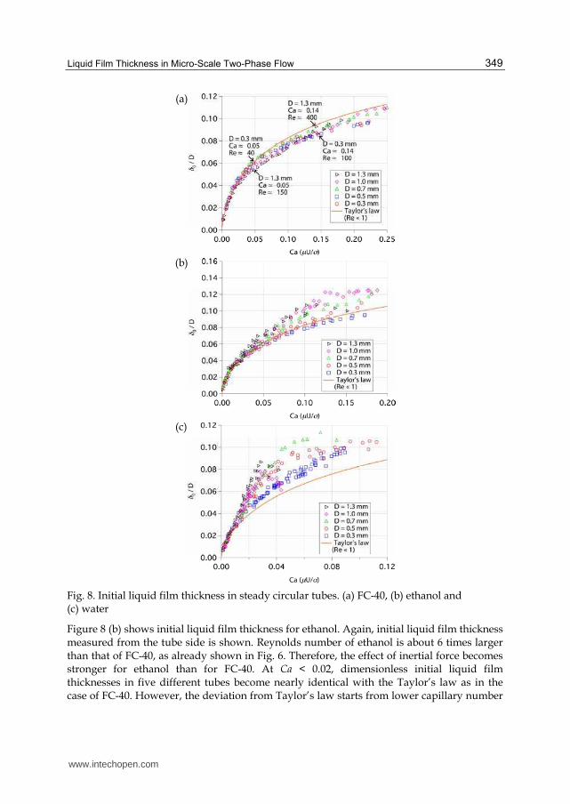
Figure 8 (a) shows initial liquid film thicknesses normalized by tube diameter against capillary number, Ca = ┤U/σ, in steady circular tubes with FC-40. Liquid film thickness is measured from tube side in a horizontal flow. The solid line in Fig. 8 is an empirical fitting curve of Taylor’s experimental data proposed by Aussillous and Quere (2000).
Ca
DCa
2
30
2h 3
0.67
1 3.35
δ=
+
, (11)
Equation (11) is called Taylor’s law. The working fluids in Taylor’s experiments were highly viscous such as glycerol and sugar-water syrup. Therefore, Reynolds number in Taylor’s experiment was small and the inertial force is negligible. At Ca < 0.025, dimensionless initial liquid film thicknesses of five tubes become nearly identical with Taylor’s law, which means that inertial force can be ignored, and the dimensionless initial liquid film thickness is determined only by capillary number. As capillary number increases, all data become smaller than the Taylor’s law. At 0.025 < Ca < 0.10, initial liquid film thickness decreases as tube diameter increases. For example, initial liquid film thickness of 1.3 mm inner diameter tube is lower than that of 0.3 mm tube at Ca ≈ 0.05. Reynolds numbers of 1.3 mm and 0.3 mm tubes are Re = 151 and 34 at Ca = 0.05. However, this trend is inverted as capillary number is increased. At Ca > 0.15, initial liquid film thickness starts to increase with Reynolds number.
www.intechopen.com
Liquid Film Thickness in Micro-Scale Two-Phase Flow
349
(a)
(b)
(c)
Fig. 8. Initial liquid film thickness in steady circular tubes. (a) FC-40, (b) ethanol and (c) water
Figure 8 (b) shows initial liquid film thickness for ethanol. Again, initial liquid film thickness measured from the tube side is shown. Reynolds number of ethanol is about 6 times larger than that of FC-40, as already shown in Fig. 6. Therefore, the effect of inertial force becomes stronger for ethanol than for FC-40. At Ca < 0.02, dimensionless initial liquid film thicknesses in five different tubes become nearly identical with the Taylor’s law as in the case of FC-40. However, the deviation from Taylor’s law starts from lower capillary number
www.intechopen.com
Two Phase Flow, Phase Change and Numerical Modeling
350
for the ethanol case. At large capillary numbers, all data are larger than the Taylor’s law. Inertial force is often neglected in micro two phase flows, but it is clear that the inertial force should be considered from this Reynolds number range. In Fig. 8 (b), dimensionless initial liquid film thickness in 1.3 mm inner diameter tube shows different trend at Ca > 0.12, showing some scattering. Reynolds number of ethanol in 1.3 mm inner diameter tube becomes Re ≈ 2000 at Ca ≈ 0.12. Thus, this different trend is considered to be the effect of flow transition from laminar to turbulent. Figure 8 (c) shows initial liquid film thickness for water. At Re > 2000, initial liquid film thickness does not increase but remains nearly constant with some scattering. This tendency is found again when Reynolds number exceeds approximately Re ≈ 2000. The deviation from Taylor’s law starts from the lower capillary number than FC-40 and ethanol. Dimensionless initial liquid film thickness of water shows much larger values than that of ethanol and Taylor’s law. In the case of 1.3 mm inner diameter tube, dimensionless initial liquid film thickness is nearly 2 times larger than the Taylor’s law at Ca ≈ 0.03. It is clearly seen that inertial force has a strong effect on liquid film thickness even in the Reynolds number range of Re < 2000.
3.1.2 Scaling analysis for circular tubes
Bretherton (1961) proposed a theoretical correlation for the liquid film thickness with lubrication equations as follows:
U
D
2
30
h
30.643
2
δ µσ
= . (12)
Aussillous and Quere (2000) modified Bretherton’s analysis, and replaced the bubble nose curvature κ = 1/(Dh/2) with κ = 1/{(Dh/2)-δ0}. In their analysis, the momentum balance and the curvature matching between the bubble nose and the transition region are expressed as follows:
( )
U
D
2
h 0
1~
2
ρ σλ λ δ
− , (13)
( )D
02
h 0
~2
δ σλ δ−
. (14)
where λ is the length of the transition region as shown in Fig. 9. Eliminating λ from Eqs. (13) and (14), they obtained following relation for dimensionless liquid film thickness:
Ca
DCa
2
30
2h 3
~2
1
δ
+
. (15)
In Eq. (15), dimensionless liquid film thickness asymptotes to a finite value due to the term Ca2/3 in the denominator. Based on Eq. (15), Taylor’s experimental data was fitted as Eq. (11). If inertial force effect is taken into account, the momentum balance (13) should be expressed as follows:
www.intechopen.com
Liquid Film Thickness in Micro-Scale Two-Phase Flow
351
( )
U U
D
2
20 h 0
1~
2
µ σ ρδ λ δ λ
−
− , (16)
Using Eqs. (14) and (16), we can obtain the relation for initial liquid film thickness δ0/Dh as:
( )
Ca
DCa We
2
30
2 2h 3 3
~
1
δ
′+ −
, (17)
where Weber number is defined as We’ = ρU2((Dh/2)-δ0)/σ. Equation (17) is always larger than Eq. (15) because the sign in front of Weber number is negative. Therefore, Eq. (17) can express the increase of the liquid film thickness with Weber number. In addition, Heil (2001) reported that inertial force makes the bubble nose slender and increases the bubble nose curvature at finite Reynolds numbers. It is also reported in Edvinsson & Irandoust (1996) and Kreutzer et al. (2005) that the curvature of bubble nose increases with Reynolds and capillary numbers. This implies that curvature term κ = 1/{(Dh/2)-δ0} in momentum equation (16) should be larger for larger Reynolds and capillary numbers. We assume that this curvature change can be expressed by adding a modification function of Reynolds and capillary numbers to the original curvature term κ = 1/{(Dh/2)-δ0} as:
( )
( )f Ca
Dh 0
1 Re,
2κ
δ
+=
−, (18)
Substituting Eq. (18) into Eqs. (14) and (16), we obtain:
( )( ) ( )
Ca
DWe
Ca f Caf Ca
23
02
32h3
~2
1 Re, 11 Re,
δ
′+ + − +
. (19)
If all the terms with Re, Ca and We can be assumed to be small, we may simplify Eq. (19) as:
( ) ( )
Ca
DCa f Ca g We
23
02
h 3
~2
1 Re,
δ
′+ + −
. (20)
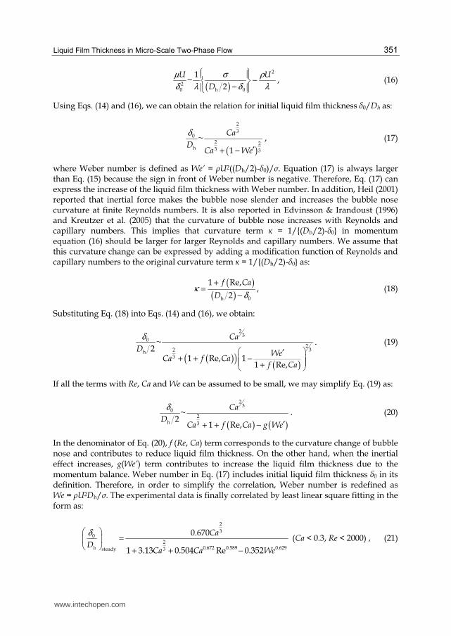
In the denominator of Eq. (20), f (Re, Ca) term corresponds to the curvature change of bubble nose and contributes to reduce liquid film thickness. On the other hand, when the inertial effect increases, g(We’) term contributes to increase the liquid film thickness due to the momentum balance. Weber number in Eq. (17) includes initial liquid film thickness δ0 in its definition. Therefore, in order to simplify the correlation, Weber number is redefined as We = ρU2Dh/σ. The experimental data is finally correlated by least linear square fitting in the form as:
h
Ca
DCa Ca We
2
30
20.672 0.589 0.6293steady
0.670
1 3.13 0.504 Re 0.352
δ = + + −
(Ca < 0.3, Re < 2000) , (21)
www.intechopen.com
Two Phase Flow, Phase Change and Numerical Modeling
352
where Ca = ┤U/σ and Re = ρUDh/┤ and We = ρU2Dh/σ. As capillary number approaches zero, Eq. (21) should follow Talors’s law (11), so the coefficient in the numerator is taken as 0.670. If Reynolds number becomes larger than 2000, initial liquid film thickness is fixed at a constant value at Re = 2000. Figures 10 and 11 show the comparison between the experimental data and the prediction of Eq. (20). As shown in Fig. 11, the present correlation can predict δ0 within the range of ±15% accuracy.
Fig. 9. Schematic diagram of the force balance in bubble nose, transition and flat film regions in circular tube slug flow
Fig. 10. Predicted initial liquid film thickness δ0 by Eq. (21)
Fig. 11. Comparison between predicted and measured initial liquid film thicknesses δ0
www.intechopen.com
Liquid Film Thickness in Micro-Scale Two-Phase Flow
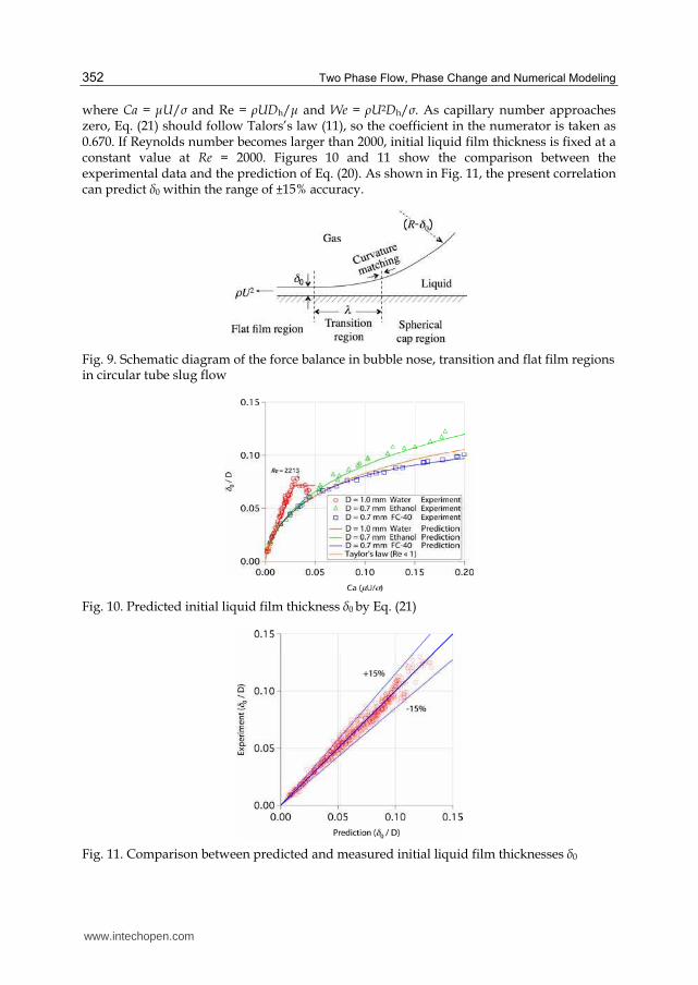
Dimensionless bubble radii Rcenter and Rcorner are the common parameters used in square channels:
RD0 _ center
center
h
21
δ= − , (22)
RD
0 _ cornercorner
h
22
δ= − . (23)
It should be noted that initial liquid film thickness at the corner δ0_corner in Eq. (23) is defined as a distance between air-liquid interface and the corner of circumscribed square which is shown as a white line in Fig. 2(b). When initial liquid film thickness at the channel center δ0_center is zero, Rcenter becomes unity. If the interface shape is axisymmetric, Rcenter becomes identical to Rcorner.
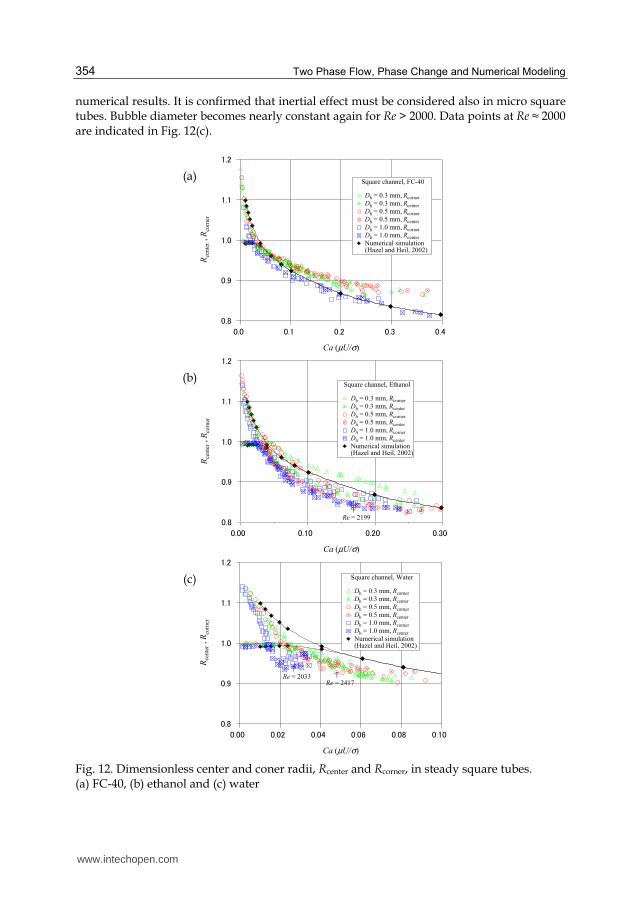
Figure 12(a) shows Rcenter and Rcorner against capillary number for FC-40. The solid lines in
Fig. 12 are the numerical simulation results reported by Hazel & Heil (2002). In their
simulation, inertial force term was neglected, and thus it can be considered as the low
Reynolds number limit. Center radius Rcenter is almost unity at capillary number less than
0.03. Thus, interface shape is non-axisymmetric for Ca < 0.03. For Ca > 0.03, Rcenter becomes
nearly identical to Rcorner, and the interface shape becomes axisymmetric. In Fig. 12,
measured bubble radii in Dh = 0.3 and 0.5 mm channels are almost identical, and they are
larger than the numerical simulation result. On the other hand, the bubble radii in Dh = 1.0
mm channel are smaller than those for the smaller channels. As capillary number
approaches zero, liquid film thickness in a micro circular tube becomes zero. In micro
square tubes, liquid film δ0_corner still remains at the channel corner even at zero capillary
number limit. Corner radius Rcorner reaches an asymptotic value smaller than 2 as
investigated in Wong et al.’s numerical study (1995a, b). This asymptotic value will be
discussed in the next section. Figure 12(b) shows Rcenter and Rcorner for ethanol. Similar to the trend found in FC-40 experiment, Rcenter is almost unity at low capillary number. Most of the experimental data are smaller than the numerical result. Transition capillary number, which is defined as the capillary number when bubble shape changes from non-axisymmetric to axisymmetric, becomes smaller as Dh increases. For Dh = 1.0 mm square tube, Rcenter is almost identical to Rcorner beyond this transition capillary number. However, for Dh = 0.3 and 0.5 mm tubes, Rcenter is smaller than Rcorner even at large capillary numbers. At the same capillary number, both Rcenter and Rcorner decrease as Reynolds number increases. For Ca > 0.17, Rcenter and Rcorner in Dh = 1.0 mm square tube becomes nearly constant. It is considered that this trend is attributed to laminar-turbulent transition. At Ca ≈ 0.17, Reynolds number of ethanol in Dh = 1.0 mm channel becomes nearly Re ≈ 2000 as indicated in Fig. 12(b). Center and coner radii, Rcenter and Rcorner, for water are shown in Fig. 12(c). Center radius Rcenter is again almost unity at low capillary number. Transition capillary numbers for Dh = 0.3, 0.5 and 1.0 mm square channels are Ca = 0.025, 0.2 and 0.014, respectively. These values are much smaller than those for ethanol and FC-40. Due to the strong inertial effect, bubble diameter of the water experiment is much smaller than those of other fluids and the
www.intechopen.com
Two Phase Flow, Phase Change and Numerical Modeling
354
numerical results. It is confirmed that inertial effect must be considered also in micro square tubes. Bubble diameter becomes nearly constant again for Re > 2000. Data points at Re ≈ 2000 are indicated in Fig. 12(c).
(a)
ゲ.コ
ゲ.ゲ
ゲ.ケ
ケ.ズ
ケ.ス
Rce
nte
r , R
corn
er
ケ.サケ.ゴケ.コケ.ゲケ.ケ
Ca (µU/σ)
Square channel, FC-40
Dh = 0.3 mm, Rcorner
Dh = 0.3 mm, Rcenter
Dh = 0.5 mm, Rcorner
Dh = 0.5 mm, Rcenter
Dh = 1.0 mm, Rcorner
Dh = 1.0 mm, Rcenter
Numerical simulation (Hazel and Heil, 2002)
x
(b)
ゲ.コ
ゲ.ゲ
ゲ.ケ
ケ.ズ
ケ.ス
Rce
nte
r , R
corn
er
ケ.ゴケケ.コケケ.ゲケケ.ケケ
Ca (µU/σ)
Square channel, Ethanol
Dh = 0.3 mm, Rcorner
Dh = 0.3 mm, Rcenter
Dh = 0.5 mm, Rcorner
Dh = 0.5 mm, Rcenter
Dh = 1.0 mm, Rcorner
Dh = 1.0 mm, Rcenter
Numerical simulation (Hazel and Heil, 2002)
↑Re = 2199
x
(c)
ゲ.コ
ゲ.ゲ
ゲ.ケ
ケ.ズ
ケ.ス
Rce
nte
r , R
corn
er
ケ.ゲケケ.ケスケ.ケ6ケ.ケサケ.ケコケ.ケケ
Ca (µU/σ)
Square channel, Water
Dh = 0.3 mm, Rcorner
Dh = 0.3 mm, Rcenter
Dh = 0.5 mm, Rcorner
Dh = 0.5 mm, Rcenter
Dh = 1.0 mm, Rcorner
Dh = 1.0 mm, Rcenter
Numerical simulation (Hazel and Heil, 2002)
↑Re = 2033 ↑
Re = 2417
x
Fig. 12. Dimensionless center and coner radii, Rcenter and Rcorner, in steady square tubes. (a) FC-40, (b) ethanol and (c) water
www.intechopen.com
Liquid Film Thickness in Micro-Scale Two-Phase Flow
355
3.2.2 Scaling analysis for square tubes
Figure 13 shows the schematic diagram of the force balance in the transition region in square tubes. Momentum equation and curvature matching in the transition region are expressed as follows:
( )U U2
1 220
1~
µ ρσ κ κ
δ λ λ− − , (24)
01 22
~δ
κ κλ
− , (25)
where, κ1 and κ2 are the curvatures of bubble nose and flat film region, respectively. In the
present experiment, δ0_corner does not become zero but takes a certain value as Ca → 0. Figure
14 shows the schematic diagram of the interface shape at Ca → 0. In Fig. 14, air-liquid
interface is assumed as an arc with radius r. Then, κ2 can be expressed as follows:
r
2
0 _ corner
1 2 1κ
δ−
= = . (26)
Fig. 13. Schematic diagram of the force balance in bubble nose, transition and flat film regions in square
Fig. 14. Schematic diagram of the gas liquid interface profile at Ca → 0
If bubble nose is assumed to be a hemisphere of radius Dh/2, the curvature at bubble nose
becomes κ1 = 2/(Dh/2). This curvature κ1 should be larger than the curvature of the flat film
region κ2 according to the momentum balance, i.e. 1 2κ κ≥ . From this restraint, the relation of
Dh and δ0_corner is expressed as follows:
www.intechopen.com
Two Phase Flow, Phase Change and Numerical Modeling
356
hD 0 _ corner
2 2 1
2 δ−
≥ . (27)
From Eqs. (23) and (27), the maximum value of Rcorner can be determined as follows:
Rcorner 1.171≤ . (28)
From Fig. 12, the interface shape becomes nearly axisymmetric as capillary number increases. Here, bubble is simply assumed to be hemispherical at bubble nose and cylindrical at the flat film region, i.e. Rcorner = Rcenter. Under such assumption, the curvatures
κ1 and κ2 in Eqs. (24) and (25) can be rewritten as follows:
hD
1
0 _ corner
2
2κ
δ=
−, (29)
hD
2
0 _ corner
1
2κ
δ=
−. (30)
We can obtain the relation for δ0_corner from Eqs. (24), (25), (29) and (30) as:
( )h
Ca
DCa We
2
30 _ corner
2 23 3
2
1
δ≈
′+ −
, (31)
where We′ is the Weber number which includes δ0_corner in its definition. Thus, We′ is
replaced by We = ρU2Dh/σ for simplicity. The denominator of R.H.S in Eq. (31) is also simplified with Taylor expansion. From Eqs. (28) and (31), Rcorner is written as follows:
Ca
R
Ca We
2
3
corner 2
3
2 2~1.171
1
−
+ −
. (32)
The experimental correlation for Rcorner is obtained by optimizing the coefficients and exponents in Eq. (32) with the least linear square method as follows:
Ca
R
Ca We
2
3
corner 20.2153
2.431.171
1 7.28 0.255
= −
+ −
(Re < 2000) , (33)
( )( )
RR
R R
corner
center
corner corner
1 1
1
>≅
≤ (Re < 2000) . (34)
From Eq. (34), Rcenter becomes unity at small capillary number. However, δ0_center still has a finite value even at low Ca, which means that Rcenter should not physically reach unity.
Further investigation is required for the accurate scaling of δ0_center and Rcenter at low Ca. As capillary number increases, interface shape becomes nearly axisymmetric and Rcenter becomes identical to Rcorner. As capillary number approaches zero, Rcorner takes an asymptotic
www.intechopen.com
Liquid Film Thickness in Micro-Scale Two-Phase Flow
357
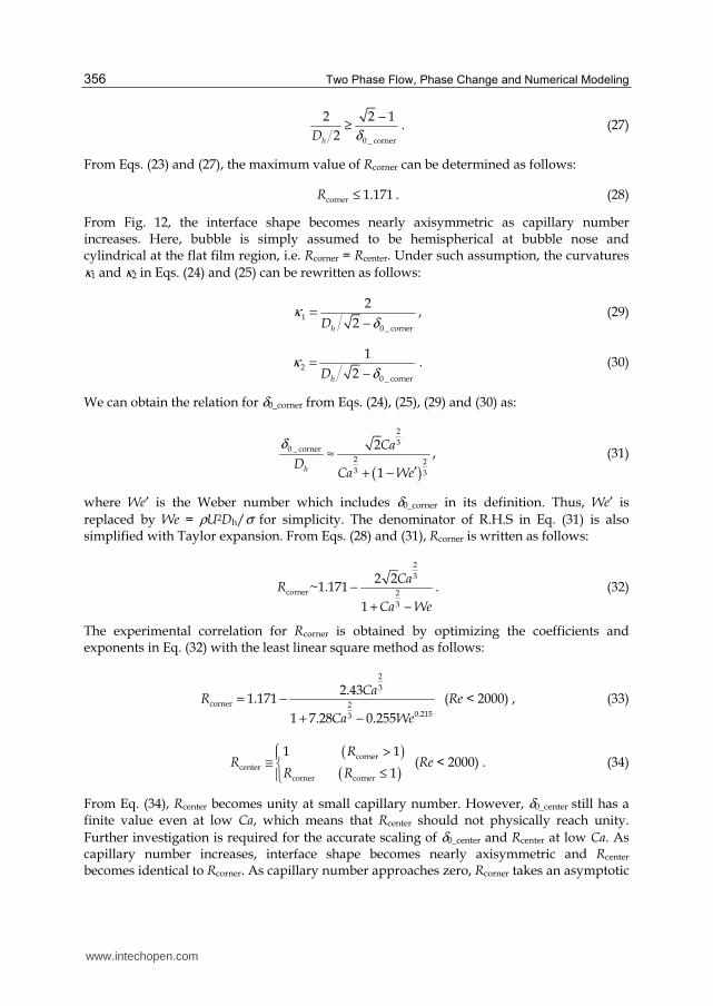
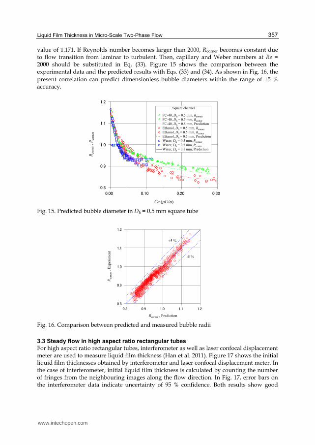
value of 1.171. If Reynolds number becomes larger than 2000, Rcorner becomes constant due to flow transition from laminar to turbulent. Then, capillary and Weber numbers at Re = 2000 should be substituted in Eq. (33). Figure 15 shows the comparison between the experimental data and the predicted results with Eqs. (33) and (34). As shown in Fig. 16, the
present correlation can predict dimensionless bubble diameters within the range of ±5 % accuracy.
ゲ.コ
ゲ.ゲ
ゲ.ケ
ケ.ズ
ケ.ス
Rce
nte
r , R
corn
er
ケ.ゴケケ.コケケ.ゲケケ.ケケ
Ca (µU/σ)
Square channel
FC-40, Dh = 0.5 mm, Rcorner
FC-40, Dh = 0.5 mm, Rcenter
FC-40, Dh = 0.5 mm, Prediction
Ethanol, Dh = 0.5 mm, Rcorner
Ethanol, Dh = 0.5 mm, Rcenter
Ethanol, Dh = 0.5 mm, Prediction
Water, Dh = 0.5 mm, Rcorner
Water, Dh = 0.5 mm, Rcenter
Water, Dh = 0.5 mm, Prediction
Fig. 15. Predicted bubble diameter in Dh = 0.5 mm square tube
ゲ.コ
ゲ.ゲ
ゲ.ケ
ケ.ズ
ケ.ス
Rco
rner
, E
xper
imen
t
ゲ.コゲ.ゲゲ.ケケ.ズケ.ス
Rcorner , Prediction
+5 %
-5 %
Fig. 16. Comparison between predicted and measured bubble radii
3.3 Steady flow in high aspect ratio rectangular tubes
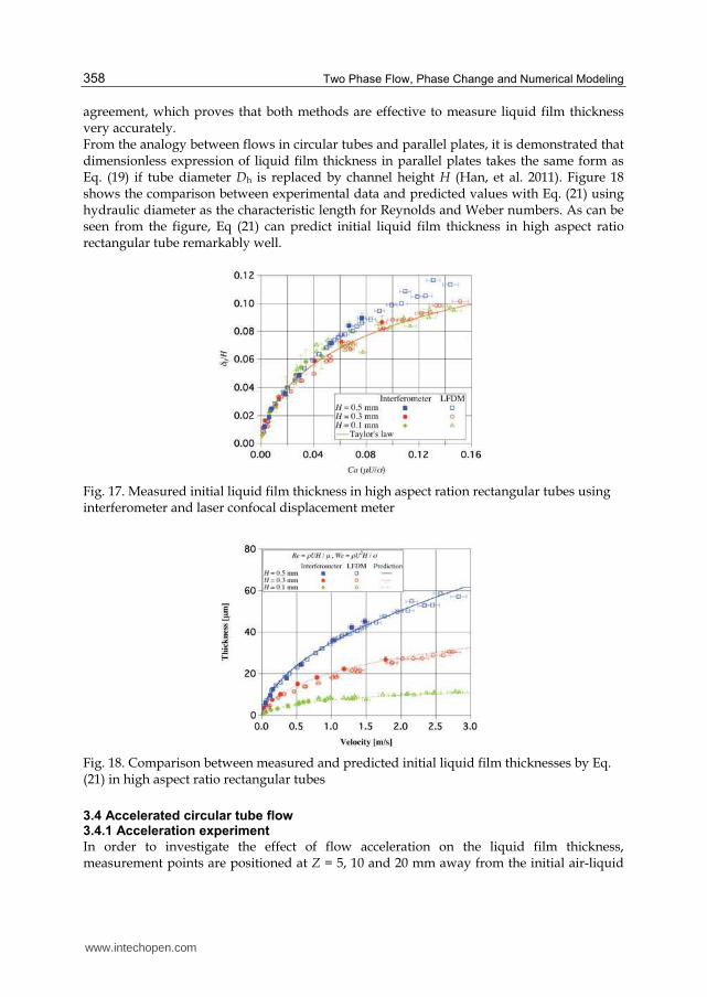
For high aspect ratio rectangular tubes, interferometer as well as laser confocal displacement meter are used to measure liquid film thickness (Han et al. 2011). Figure 17 shows the initial liquid film thicknesses obtained by interferometer and laser confocal displacement meter. In the case of interferometer, initial liquid film thickness is calculated by counting the number of fringes from the neighbouring images along the flow direction. In Fig. 17, error bars on the interferometer data indicate uncertainty of 95 % confidence. Both results show good
www.intechopen.com
Two Phase Flow, Phase Change and Numerical Modeling
358
agreement, which proves that both methods are effective to measure liquid film thickness very accurately. From the analogy between flows in circular tubes and parallel plates, it is demonstrated that dimensionless expression of liquid film thickness in parallel plates takes the same form as Eq. (19) if tube diameter Dh is replaced by channel height H (Han, et al. 2011). Figure 18 shows the comparison between experimental data and predicted values with Eq. (21) using hydraulic diameter as the characteristic length for Reynolds and Weber numbers. As can be seen from the figure, Eq (21) can predict initial liquid film thickness in high aspect ratio rectangular tube remarkably well.
Fig. 17. Measured initial liquid film thickness in high aspect ration rectangular tubes using interferometer and laser confocal displacement meter
Fig. 18. Comparison between measured and predicted initial liquid film thicknesses by Eq. (21) in high aspect ratio rectangular tubes
In order to investigate the effect of flow acceleration on the liquid film thickness, measurement points are positioned at Z = 5, 10 and 20 mm away from the initial air-liquid
www.intechopen.com
Liquid Film Thickness in Micro-Scale Two-Phase Flow
359
interface position, Z = 0 mm, as shown in Fig. 19. For the convenience in conducting experiments, circular tubes are used. The position of laser confocal displacement meter is fixed by XYZ stage accurately with high-speed camera and illumination light. Air/liquid interface is moved to the initial position (Z = 0 mm) with the actuator motor to correctly set the distance between the initial position and the measurement position. The distance is measured from the image captured by the high-speed camera. The bubble acceleration is simply expressed assuming that the acceleration is uniform when the flow is accelerated to a certain velocity as follows:
U
aZ
2
2= , (35)
where U is the bubble velocity at the measurement position. Since measurement position is fixed in the present experiment, acceleration becomes larger for larger capillary numbers. At given capillary number, in other words at given velocity, bubble acceleration decreases as the distance Z increases, which is apparent from Eq. (35). Surface tension of water is much larger than those of ethanol and FC-40, which means that bubble velocity of water is much higher at same capillary number. For example, bubble velocities of water, ethanol and FC-40 at Ca = 0.1 are 7.77, 1.99 and 0.27 m/s, respectively. Therefore, bubble acceleration of water becomes much larger than those of ethanol or FC-40 at fixed capillary number.
Fig. 19. Initial gas-liquid interface position and the measuring points
3.4.2 Liquid film thicknesses in accelerated flows
Figure 20 shows the dimensionless initial liquid film thickness in Dh = 1.0 mm circular tube for FC-40, ethanol and water. As shown in the figure, initial liquid film thickness under accelerated condition can be divided into two regions. At small capillary numbers, initial liquid film thickness is identical to the steady case. As capillary number increases, initial liquid film thickness deviates from the steady case and becomes much thinner.
3.4.3 Scaling analysis for accelerated flows
Under accelerated condition, velocity profile in the preceding liquid slug is different from that in the steady flow, and bubble nose curvature is affected by this velocity profile change. This is considered to be the reason for the decrease of the liquid film thickness. Under the bubble acceleration condition, bubble nose curvature is modified as:
hDh
0
1~
2
κδ
× − , (36)
www.intechopen.com
Two Phase Flow, Phase Change and Numerical Modeling
360
(a) (b)
(c)
Fig. 20. Initial liquid film thicknesses in accelerated circular tubes. (a) FC-40, (b) ethanol and (c) water
where h is the modification coefficient which accounts for the acceleration effect. If the curvature of bubble nose in the R.H.S. of Eqs. (13) and (14) is replaced by Eq. (36), dimensionless initial liquid film thickness in accelerated flow can be written as follows:
Ca h
D Ca h
213
02
13h acceleration
0.67~
1 3.35
δ −
−
⋅ + ⋅ , (37)
Modification coefficient h can be expressed from Eq. (37) as:
( )
Cah Ca
Dacceleration
2233
0 h
0.67~ 3.35
δ− . (38)
Moriyama & Inoue (1996) and Aussillous & Quere (2000) reported that liquid film generation is restricted by the viscous boundary layer developed in the liquid slug when viscous boundary layer is thin. Viscous boundary layer thickness δ* can be scaled as follows:
┥ZU
12
* ~δ , (39)
www.intechopen.com
Liquid Film Thickness in Micro-Scale Two-Phase Flow
361
where ν is the kinematic viscosity. Although viscous boundary layer thickness is independent of tube diameter, absolute liquid film thickness is nearly proportional to the tube diameter as shown in Fig. 20. This indicates that viscous boundary layer is not the proper parameter to scale the acceleration effect. It is considered that surface tension should also play an important role in accelerated flows as in the steady case. Under the accelerated condition, Bond number based on bubble acceleration a is introduced as follows:
aD
B2
oρ
σ= . (40)
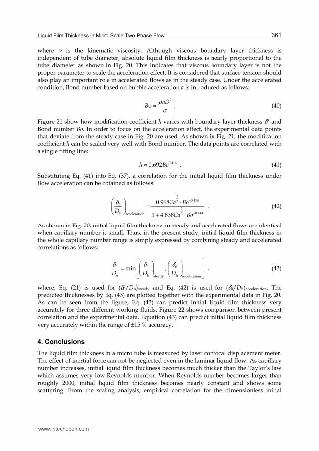
Figure 21 show how modification coefficient h varies with boundary layer thickness δ* and Bond number Bo. In order to focus on the acceleration effect, the experimental data points that deviate from the steady case in Fig. 20 are used. As shown in Fig. 21, the modification coefficient h can be scaled very well with Bond number. The data points are correlated with a single fitting line:
h Bo0.4140.692= . (41)
Substituting Eq. (41) into Eq. (37), a correlation for the initial liquid film thickness under flow acceleration can be obtained as follows:
Ca Bo
DCa Bo
20.4143
02
0.414h 3acceleration
0.968
1 4.838
δ −
−
⋅= + ⋅
. (42)
As shown in Fig. 20, initial liquid film thickness in steady and accelerated flows are identical when capillary number is small. Thus, in the present study, initial liquid film thickness in the whole capillary number range is simply expressed by combining steady and accelerated correlations as follows:
hD D D0 0 0
h hsteady acceleration
min ,δ δ δ =
, (43)
where, Eq. (21) is used for (δ0/Dh)steady and Eq. (42) is used for (δ0/Dh)acceleration. The predicted thicknesses by Eq. (43) are plotted together with the experimental data in Fig. 20. As can be seen from the figure, Eq. (43) can predict initial liquid film thickness very accurately for three different working fluids. Figure 22 shows comparison between present correlation and the experimental data. Equation (43) can predict initial liquid film thickness
very accurately within the range of ±15 % accuracy.
4. Conclusions
The liquid film thickness in a micro tube is measured by laser confocal displacement meter. The effect of inertial force can not be neglected even in the laminar liquid flow. As capillary number increases, initial liquid film thickness becomes much thicker than the Taylor’s law which assumes very low Reynolds number. When Reynolds number becomes larger than roughly 2000, initial liquid film thickness becomes nearly constant and shows some scattering. From the scaling analysis, empirical correlation for the dimensionless initial
www.intechopen.com
Two Phase Flow, Phase Change and Numerical Modeling
362
liquid film thickness based on capillary number, Reynolds number and Weber number is
proposed. The proposed correlation can predict the initial liquid film thickness within ±15% accuracy.
(a)
(b)
Fig. 21. RHS of Eq. (38) plotted against (a) boundary layer thickness and (b) Bond number
Fig. 22. Comparison between predicted and measured initial liquid film thicknesses δ0 in accelerated flows
www.intechopen.com
Liquid Film Thickness in Micro-Scale Two-Phase Flow
363
In square tubes, liquid film formed at the center of the side wall becomes very thin at small capillary numbers. However, as capillary number increases, the bubble shape becomes nearly axisymmetric. As Reynolds number increases, flow transits from non-axisymmetric to axisymmetric at smaller capillary numbers. Initial liquid film thickness in high aspect ratio rectangular tubes can be predicted well using the circular tube correlation provided that hydraulic diameter is used for Reynolds and Weber numbers. It is also shown that results from interferometer and laser confocal displacement meter give nearly identical results, which proves the reliability of both methods. When the flow is accelerated, velocity profile in the preceding liquid slug strongly affects the liquid film formation. Liquid film becomes much thinner as flow is further accelerated. Experimental correlation for the initial liquid film thickness under accelerated condition is proposed by introducing Bond number. In order to develop precise micro-scale two-phase heat transfer models, it is necessary to consider the effect of flow acceleration on the liquid film formation.
5. Acknowledgment
We would like to thank Prof. Kasagi, Prof. Suzuki and Dr. Hasegawa for the fruitful discussions and suggestions. This work is supported through Grant in Aid for Scientific Research (No. 20560179) and Global COE program, Mechanical Systems Innovation, by MEXT, Japan.
6. References
Aussillous, P. & Quere, D. (2000). Quick deposition of a fluid on the wall of a tube, Physics of Fluids, 12(10), 2367-2371.
Bretherton, F. P. (1961). The motion of long bubbles in tubes, Journal of Fluid Mechanics, 10(2), 166-188.
Cooper, M. G. (1969). The microlayer and bubble growth in nucleate pool boiling, International Journal of Heat and Mass Transfer, 12, 915-933.
Cox, B. G. (1964). An experimental investigation of the streamlines in viscous fluid expelled from a tube, Journal of Fluid Mechanics, 20, 193-200.
Edvinsson, R. K. & Irandoust, S. (1996). Finite-element analysis of taylor flow, AIChE Journal, 42(7), 1815-1823.
Han, Y. & Shikazono, N. (2009a). Measurement of the liquid film thickness in micro tube slug flow, International Journal of Heat and Fluid Flow, 30(5), 842-853.
Han, Y. & Shikazono, N. (2009b). Measurement of liquid film thickness in micro square channel, International Journal of Multiphase Flow, 35(10), 896-903.
Han, Y. & Shikazono, N. (2010). The effect of bubble acceleration on the liquid film thickness in micro tubes, International Journal of Heat and Fluid Flow, 31(4), 630-639.
Han, Y.; Shikazono, N. & Kasagi, N. (2009b). Measurement of liquid film thickness in a micro parallel channel with interferometer and laser focus displacement meter, International Journal of Multiphase Flow, 37(1), 36-45.
Hazel, A. L. & Heil, M. (2002). The steady propagation of a semi-infinite bubble into a tube of elliptical or rectangular cross-section, Journal of Fluid Mechanics, 470, 91-114.
Hazuku, T.; Fukamachi, N.; Takamasa, T.; Hibiki, T. & Ishii, M. (2005). Measurement of liquid film in microchannels using a laser focus displacement meter, Experiments in Fluids, 38(6), 780-788.
www.intechopen.com
Two Phase Flow, Phase Change and Numerical Modeling
364
Heil, M. (2001). Finite Reynolds number effects in the Bretherton problem, Phys. of Fluids, 13(9), 2517-2521.
Hurlburt, E. T. & Newell, T. A. (1996). Optical measurement of liquid film thickness and wave velocity in liquid film flows, Experiments in Fluids, 21, 357-362.
Kenning, D. B. R.; Wen, D. S.; Das, K. S. & Wilson, S. K. (2006). Confined growth of a vapour bubble in a capillary tube at initially uniform superheat: Experiments and modeling, International Journal of Heat and Mass Transfer, 49(23-24), 4653-4671.
Kreutzer, M. T.; Kapteijn, F.; Moulijn, J. A.; Kleijn, C. R. & Heiszwolf, J. J. (2005). Inertial and interfacial effects on pressure drop of Taylor flow in capillaries, AIChE Journal, 51(9), 2428-2440.
Moriyama, K. & Inoue, A. (1996). Thickness of the liquid film formed by a growing bubble in a narrow gap between two horizontal plates, Transactions of the ASME, 118, 132-139.
Qu, W. & Mudawar, I. (2004). Flow boiling heat transfer in two-phase micro-channel heat sink-II. Annular two-phase flow model, International Journal of Heat Mass Transfer, 46, 3387-3401.
Saitoh, S.; Daiguji, H. & Hihara, H. (2007). Correlation for boiling heat transfer of R-134a in horizontal tubes including effect of tube diameter, International Journal of Heat Mass Transfer, 50, 5215-5225.
Schwartz, L.W.; Princen, H.M. & Kiss, A.D. (1986). On the motion of bubbles in capillary tubes, Journal of Fluid Mechanics, 172, 259–275.
Shedd, T. A. & Newell, T. A. (2004). Characteristics of the liquid film and pressure drop in horizontal, annular, two-phase flow through round, square and triangular tubes, Journal of Fluid Engineering, 126, 807-817.
Taha, T. & Cui, Z. F. (2006). CFD modelling of slug flow inside square capillaries, Chemical Engineering Science, 61, 665-675
Takamasa, T. & Kobayashi, K. (2000). Measuring interfacial waves on film flowing down tube inner wall using laser focus displacement meter, International Journal of Multiphase Flow, 26(9), 1493-1507.
Taylor, G. I. (1961). Deposition of a viscous fluid on the wall of a tube, Journal of Fluid Mechanics, 10(2), 161-165.
Thome, J. R.; Dupont, V. & Jacobi, A. M. (2004). Heat transfer model for evaporation in microchannels. Part I: presentation of the model, International Journal of Heat Mass Transfer, 47(14-16), 3375-3385.
Tibirica, C. B.; Nascimento, F. J. & Ribatski, G. (2010). Film thickness measurement techniques applied to micro-scale two-phase flow systems, Experimental Thermal and Fluid Science, 34 (4), 463-473.
Ursenbacher, T.; Wojtan, L. & Thome, J. R. (2004). Interfacial measurements in stratified types of flow. Part I: New optical measurement technique and dry angle measurements, International Journal of Multiphase Flow, 30, 107-124.
Utaka, Y.; Okuda, S. & Tasaki, Y. (2007). Structure of micro-layer and characteristics of boiling heat transfer in narrow gap mini-channel system, Transactions of the JSME, Series B, 73(733), 1929-1935.
Wong, H., Radke, C. J. & Morris, S. (1995a). The motion of long bubbles in polygonal capillaries. Part 1. Thin films, Journal of Fluid Mechanics, 292, 71-94.
Wong, H., Radke, C. J. & Morris, S. (1995b). The motion of long bubbles in polygonal capillaries. Part 2. Drag, fluid pressure and fluid flow, Journal of Fluid Mechanics, 292, 95-110.
www.intechopen.com
Two Phase Flow, Phase Change and Numerical ModelingEdited by Dr. Amimul Ahsan
ISBN 978-953-307-584-6Hard cover, 584 pagesPublisher InTechPublished online 26, September, 2011Published in print edition September, 2011
InTech ChinaUnit 405, Office Block, Hotel Equatorial Shanghai No.65, Yan An Road (West), Shanghai, 200040, China
Phone: +86-21-62489820 Fax: +86-21-62489821
The heat transfer and analysis on laser beam, evaporator coils, shell-and-tube condenser, two phase flow,nanofluids, complex fluids, and on phase change are significant issues in a design of wide range of industrialprocesses and devices. This book includes 25 advanced and revised contributions, and it covers mainly (1)numerical modeling of heat transfer, (2) two phase flow, (3) nanofluids, and (4) phase change. The firstsection introduces numerical modeling of heat transfer on particles in binary gas-solid fluidization bed,solidification phenomena, thermal approaches to laser damage, and temperature and velocity distribution. Thesecond section covers density wave instability phenomena, gas and spray-water quenching, spray cooling,wettability effect, liquid film thickness, and thermosyphon loop. The third section includes nanofluids for heattransfer, nanofluids in minichannels, potential and engineering strategies on nanofluids, and heat transfer atnanoscale. The forth section presents time-dependent melting and deformation processes of phase changematerial (PCM), thermal energy storage tanks using PCM, phase change in deep CO2 injector, and thermalstorage device of solar hot water system. The advanced idea and information described here will be fruitful forthe readers to find a sustainable solution in an industrialized society.
How to referenceIn order to correctly reference this scholarly work, feel free to copy and paste the following:
Naoki Shikazono and Youngbae Han (2011). Liquid Film Thickness in Micro-Scale Two-Phase Flow, TwoPhase Flow, Phase Change and Numerical Modeling, Dr. Amimul Ahsan (Ed.), ISBN: 978-953-307-584-6,InTech, Available from: http://www.intechopen.com/books/two-phase-flow-phase-change-and-numerical-modeling/liquid-film-thickness-in-micro-scale-two-phase-flow