I 1 I I NASA CONTRACTOR NASA CR - 54085 REPORT Ln QD 0 * Ln I = v v) z a a 7 t (CODE1 L ~CArECORI) ULASA CR OR TMX OR AD NUYEERl LIQUID HYDROGEN FILM COOLED PRESSURE TRANSDUCERS By J. Delmonte Prepared under Contract No. NAS3-2754 by ELECTRO-OPTICAL SYSTEMS, LNC Pasadena, California 6 I NATIONAL AERONAUTICS AND SPACE ADMINISTRATION WASHINGTON, D. C. DECEMBER 1964
Transcript
I 1 I I
N A S A C O N T R A C T O R NASA CR - 54085 R E P O R T
Ln QD 0 * Ln I
= v
v)
z
a a
7 t
(CODE1
L
~ C A r E C O R I ) ULASA CR OR TMX OR AD NUYEERl
LIQUID H Y D R O G E N FILM COOLED PRESSURE T R A N S D U C E R S By J. Delmonte
Prepared under Contract No. NAS3-2754 by ELECTRO-OPTICAL SYSTEMS, LNC Pasadena, California
6 I NATIONAL AERONAUTICS AND SPACE ADMINISTRATION WASHINGTON, D. C. DECEMBER 1964
NOTICE This report was prepared as an account of Government sponsored work. Neither the United States, nor the National Aeronautics and Space Administration (NASA), nor any person acting on behalf of NASA:
A,) Makes any warranty or representation, expressed or implied, with respect to the accuracy, completeness, or usefulness of the information contained in this report, or that the use of any information, apparatus, method, or process disclosed in this report may not infringe privately owned rights; or
8.) Assumes any liabilities with respect to the use of, or for damages resulting from the use of any infor- mation, apparatus, method or process disclosed in this report.
As used above, "person acting on behalf of NASA" includes any employee or contractor of NASA, or employee of such con- tractor, to the extent that such employee or contractor of NASA, or employee of such contractor ,prepares, di sseminotes, o r provides a c c e s s to, any information pursuant to h i s employment or contract with NASA, or h i s employment with such contractor.
Requests for copies of t h i s report should be referred t o
National Aeronautics and Space Administration Office of Sc ien t i f ic and Technical Information Attention: AFSS-A Washington, D. C. 20546
CONTRACTOR R E P O R T
LIQUID HYDROGEN FILM COOLED P R E S S U R E TRANSDUCERS
By J. D e l m o n t e
P r e p a r e d unde r C o n t r a c t NAS 3 - 2 7 54 E l e c t r o - O p t i c a l S y s t e m s , Inc.
300 N o r t h H a l s t e a d Street P a s a d e n a , C a l i f o r n i a
D e c e m b e r 1964
T e c h n i c a l M a n a g e m e n t M r . J a m e s W. N o r r i s
L e w i s R e s e a r c h C e n t e r C l e v e l a n d , Ohio
NATIONAL AERONAUTICS AND S P A C E ADMINISTRATION
R e a 8 I I 8 8 e 8 I 1 U I, 8 I
1 1 8
e
CONTENTS
Page
SUMMARY 1. INTRODUCTION
2. TECHNICAL DISCUSSION
2 .1 Pro to type program f o r 300°K t o 2C°K o p e r a t i o n a l p re s su re t ransducer capable of be ing cooled by l i q u i d hydrogen
Work accomplished between March 1 5 and A p r i l 25 2.2
2 .3 Review of Statement of Work
3 . RECOMMENDATIONS
3 . 1 Mechanical f e a t u r e s of EOS PT15C-2 des ign
3 .2 Four-act ive-element s i l i c o n c h i p beam
3 .3 Thermal Environment: T rans i en t and Steady S t a t e
4 . CONCLUSION
APPENDIX I -LIST OF ABBREVIATIONS
APPENDIX XI -FABRICATION OF SINGLE CHIP BEAMS IN 'SILICON
APPENDIX 111 -TABLES 1, 2 , 3 and 4
APPENDIX I V -PT1%-2 PARTS LIST
427 0 -F i n a 1 iii
1
3
3
8
13
16
16
17
17
18
ILLUSTRATIONS
F i g u r e
1
2
3
4
5
6
7
8
9
10
11
12
13
PT15C-2 p r e s s u r e t ransducer
Layout of d i f f u s e d fou r -ac t ive arm s i l i c o n s t r a i n gage beam ch ip
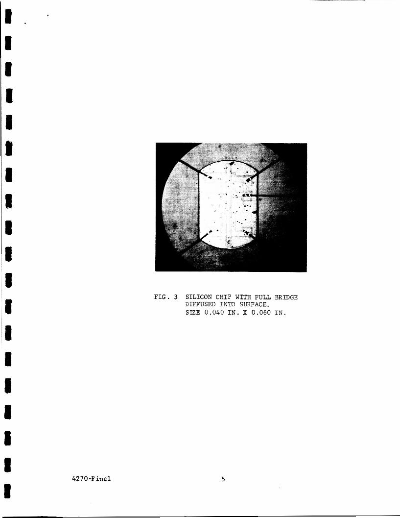
S i l i c o n ch ip wi th f u l l b r idge d i f f u s e d i n t o s u r f a c e . S i ze 0.040 in . x 0.060 i n .
Four-ac t ive arm s i l i c o n ch ips on 304 S S , some s i l i c o n c h i p s bonded, some suspended o f f t h e m e t a l ba r
Mul t ip le element s i l i c o n ch ip mounted on Inva r cons tan t stress beam
Top assembly - Pressure Transducer model PT15C-2
I n s t a l l a t i o n and c a l i b r a t i o n - S e r . No. 2 , PT15C-2
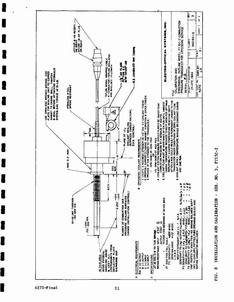
I n s t a l l a t i o n and c a l i b r a t i o n - Ser . N o . 3 , PT15C-2
I n s t a l l a t i o n and c a l i b r a t i o n - S e r . No. 4 , PT15C-2
Laboratory and f i e l d t e s t appa ra tus and p res su re system
EOS developed PT15B combustion p r e s s u r e t r a n s d u t e r with coolan t flow i n opera t ion j u s t p r i o r t o flame impingement
Oxy-hydrogen flame impingement d i r e c t l y on diaphragm of PT15B combustion p res su re t r ansduce r
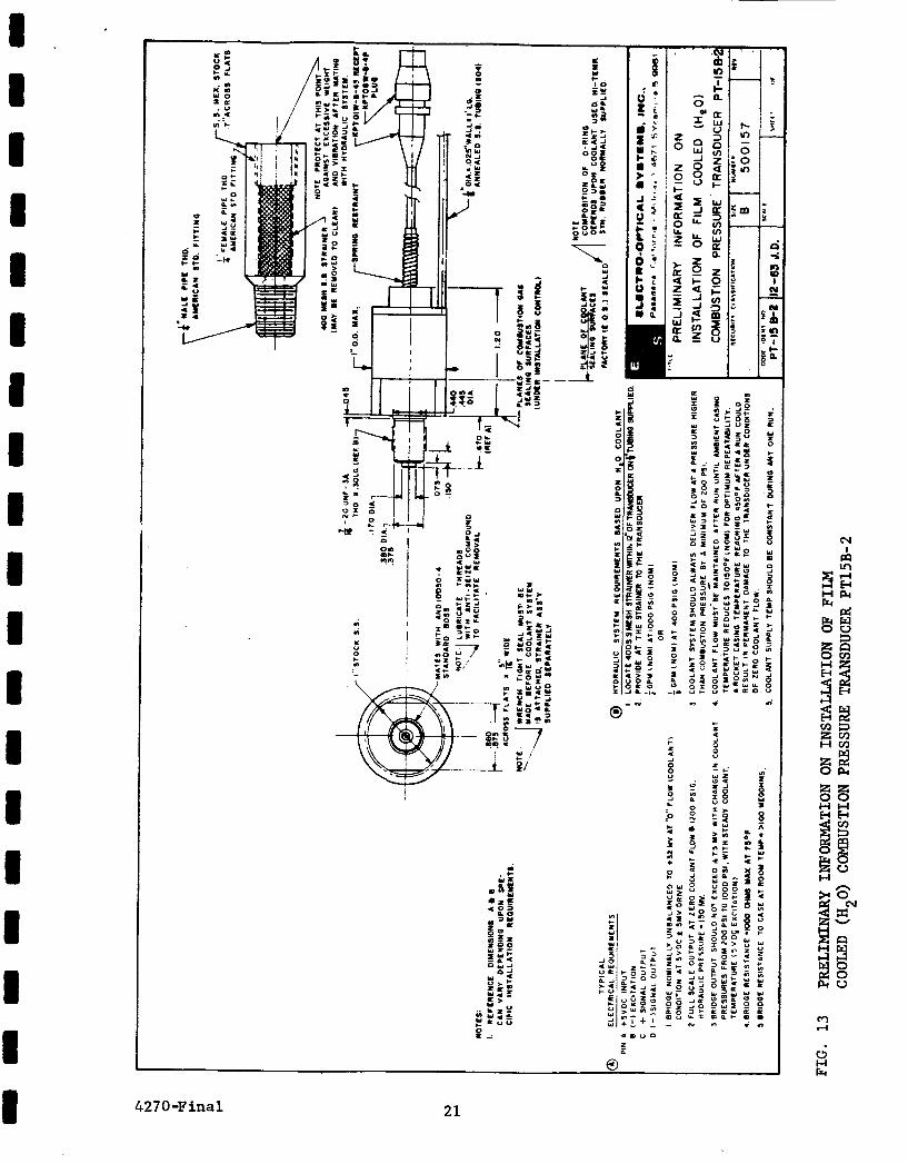
Pre l iminary information on i n s t a l l a t i o n of f i l m cooled (H20) combustion p res su re t r ansduce r PT15B-2
4270-Final V
Page
2
4
5
7
7
9
10
11
12
14
19
20
21
.
SUMMARY
The f i r s t gene ra t ion c o n s t r u c t i o n and t e s t of t h r e e
cooled combustion p r e s s u r e t r ansduce r s capable of t r ansduc ing s t eady
s t a t e as w e l l as h igh frequency p r e s s u r e p u l s e s have been s u c c e s s f u l l y
accomplished. These are embodied i n E lec t ro -Opt i ca l Systems p r e s s u r e
t r ansduce r s PT15C-2, S e r i a l Nos. 2 , 3 , and 4 , as o u t l i n e d i n P r i n t B
500160-2 Revision 3 of s u b j e c t c o n t r a c t . F igu re 1 i s a photograph of
t h e f i n i s h e d t r ansduce r .
Opt imiza t ion of e l e c t r i c a l o u t p u t , l e a d i n g t o improved performance
s p e c i f i c a t i o n s , and reassessment of i n s t a l l a t i o n d e t a i l s , r e f l e c t i n g i n
inc reased handl ing s t r e n g t h and f i e l d r e l i a b i l i t y , w i l l r e s u l t i n accu-
r a t e , rugged, and r e l i a b l e in s t rumen ta t ion capab le of s u r v i v i n g combined
environment extremes, w i th increased ou tpu t .
The e f f i c i e n c y of f i l m cool ing t h e PT15C-2 t r ansduce r w i th l i q u i d
hydrogen i s y e t t o be proven under combustion p r e s s u r e and tempera ture
c o n d i t i o n s .
s o l i d s t a t e p r e s s u r e t ransducers are capable of c r e d i t a b l e performance
t o a t least LH tempera tures with c o n t r o l l a b l e output ( s e n s i t i v i t y ) and
z e r o s h i f t . S i z e a d a p t a b i l i t y , low we igh t , good ou tpu t s t r e n g t h , an
e l e c t r i c a l s i m p l i c i t y a r e s a l i e n t f e a t u r e s of t h i s t y p e ' o f p r e s s u r
i n s t rumen ta t ion .
1. INTRODUCTION
S t a t i c tests performed to d a t e i n d i c a t e t h a t b r idge - type
2
This document c o n s t i t u t e s t h e f i n a l r e p o r t on NAS3-2754 c o n t r a c t .
It covers t h e s p e c i f i c span of time from March 15, 1964 through t h e week
ending A p r i l 25 , 1964, as w e l l as documents and summarizes t h e r e s u l t s
of t h e e n t i r e c o n t r a c t work. It inc ludes recommendations and con-
c l u s i o n s based upon t h e experience and r e s u l t s ob ta ined .
To Messrs. S. Kaye of t h e Semiconductor Department and Wm.
McLellan of t h e Mechanical Engineering Department i s due much apprec i -
a t i o n f o r t h e expediency in developing t h e highly-doped f o u r - a c t i v e
a r m s i l i c o n s t r a i n gage conf igu ra t ion and tests the reon , w i t h i n
t h e i r r e s p e c t i v e l a b o r a t o r i e s a t E lec t ro -Opt i ca l Systems, I n c . M r .
J . Frass rand of t h e Elec t ro-Opt ica l Systems, Inc . t r ansduce r l a b o r a t o r y
e x h i b i t e d unusual s k i l l i n f a b r i c a t i o n and assembly techniques .
FIG. 1 PT15C-2 PRESSURE TRANSDUCER
427 0 -F ina 1 2
2 . TECHNICAL DISCUSSION 0 0
2 . 1 Pro to type program f o r 300 K t o 20 K o p e r a t i o n a l p r e s s u r e t r a n s -
ducer capable of be ing cooled by l i q u i d hydrogen.
Phase I: From bas ic t echno log ie s p rev ious ly pursued a t
E l e c t r o 4 p t i c a l Systems and i ts s u b s i d i a r y , Micro Systems, I n c . , t h e
d i f f u s e d fou r -ac t ive element s o l i d s t a t e p i e z o r e s i s t i v e gage beam had
been s u c c e s s f u l l y proven and t ransducer *
t e s t e d .
However, t o span the tempera tures r e q u i r e d of t h i s p r o j e c t
an exhaus t ive l i t e r a t u r e search had t o be i n s t i t u t e d by t h e Semicon-
duc to r Department under M r . S. Kaye, and many i n t e n s i v e t r a i l and e r r o r
tests accomplished w i t h i n a r e l a t i v e l y s h o r t t i m e t o produce accep tab le
s i l i c o n s t r a i n gage e lements with t h e proper mechanical c o n f i g u r a t i o n ,
e l e c t r i c a l r e s i s t a n c e , temperature c o e f f i c i e n t of r e s i s t a n c e , and gage
f a c t o r . Handling c h a r a c t e r i s t i c s f o r c o n t a c t i n g an u l t i m a t e bonding
had t o be reduced t o t h e level o f t he s k i l l of average assembly
t e c h n i c i a n s .
A b e s t compromise conditio& r e s u l t e d i n r e l a t i v e l y h igh P
dopant l e v e l d i f f u s i o n i n t o t h e b u l k s i l i c o n , a lowered gage f a c t o r
of about 5 0 , a t room temperature, and a r e l a t i v e l y low temperature
c o e f f i c i e n t of resistance f o r t he f o u r i n d i v i d u a l r e s i s t a n c e s . M r .
Kaye has prepared a s e c t i o n on f a b r i c a t i o n of s i n g l e c h i p beams i n
s i l i c o n , having f o u r a c t i v e s t r a i n gage arms. See Appendix I1 i n
which fou r s i g n i f i c a n t r e fe rences a r e c i t e d .
F i n a l c h i p conf igu ra t ion i s i l l u s t r a t e d i n F i g . 2 ; an a c t u a l
photograph of t h e f o u r - a c t i v e element gage i s t o be seen i n F i g . 3 .
Phase 11: T e s t i n g the s i l i c o n element from t h e t r ansduce r
viewpoint of end use:
T h i s involved t h e mechanical, thermal , and e l e c t r i c a l
i n t e g r a t i o n of t he s i l i c o n chip w i t h a s u i t a b l e p re s su re summing d e v i c e .
The l a t t e r , an i n t e g r a l l y machined clamped diaphragm, was a l r e a d y d e f i n e d ,
s i ze -wise , n o t t o exceed 0.115 inch d iameter , because of prev ious con-
s t r a i n t s imposed by t h e a v a i l a b l e e n t r y geometry t o the r o c k e t combustion
chamber.
- % l e c t r o + p t i c a l Systems Pa ten t a p p l i c a t i o n pending.
4720-Final 3
-I--- --- 0 .ololl --
1
3 .O 0 6" I
FIG. 2 LAYOUT OF DIFFUSED FOUR-ACTIVE ARM SILICON STRAIN GAGE BEAM C H I P
I . 8
F I G . 3 S I L I C O N C H I P WITH F U L L BRIDGE DIFFUSED INTO SURFACE. S I Z E 0.040 I N . X 0.060 I N .
4270 -Final 5
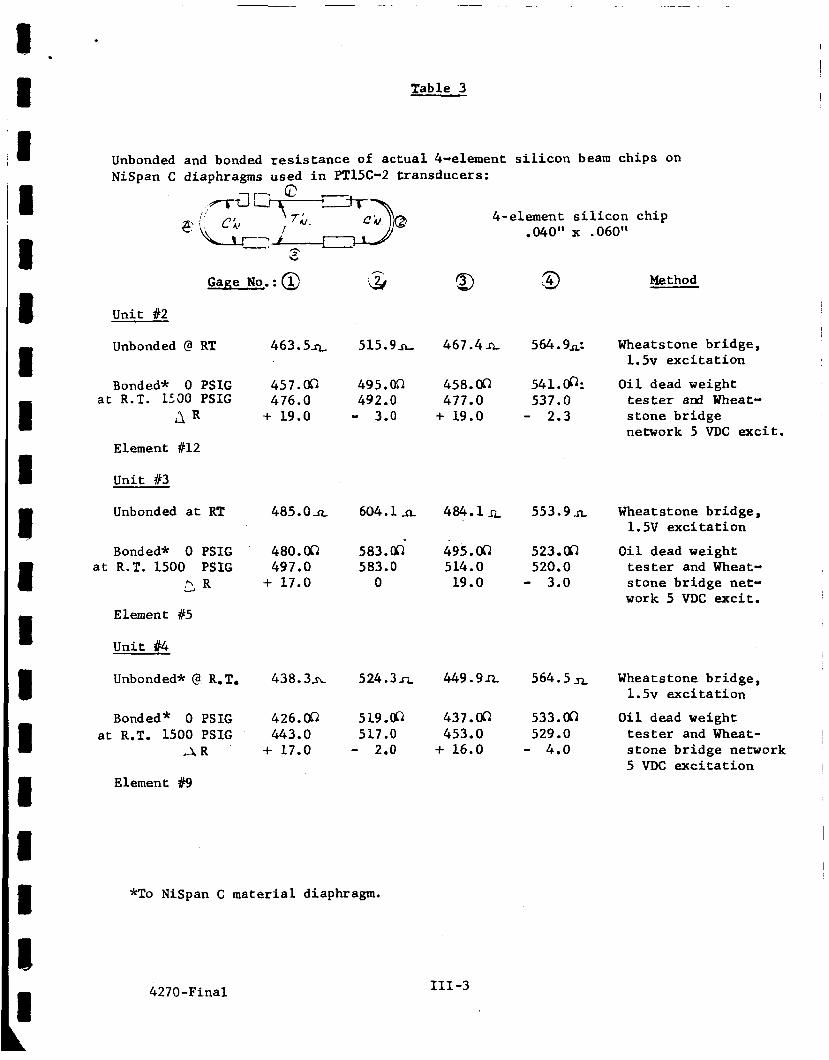
I n t e g r i t y of t h e s i l i c o n c h i p w a s a s su red by shock t e s t i n g t o
Ln and in te rmedia te tempera tures , r e p e a t e d l y , and r eco rd ing t h e changes
i n i t s f o u r r e s i s t a n c e s , i n t h e unbonded and bonded c o n d i t i o n . This was
accomplished both a t EOS's t r ansduce r l a b o r a t o r y and a t t h e Norco f a c i l -
i t y of Wyle Labora tor ies . Typica l d a t a accumulated from t h e s e t e s t s i s
shown i n Table 1 o f Appendix 111.
2
Figure 4 s h o w s t h e 304 S S t e s t s e t u p .
Figure 5 d e p i c t s t h e c h i p mounted on Inva r cons t an t s t ress
beam.
Knowing t h a t t he s i l i c o n element responds e i t h e r more o r less
l i n e a r l y w i t h i t s o r i g i n a l "clamping" s t ress (a f u n c t i o n of t h e adhes ive
used , t h e cure tempera ture , and t h e d i f f e r e n c e i n thermal c o n t r a c t i o n
between s i l i c o n and t h e diaphragm meta l ) , we decided t o b racke t thermal
expansion c o e f f i c i e n t o f t h e s i l i c o n c h i p by mounting i t on a 300 series
s t a i n l e s s s t e e l diaphragm and comparing the r e s u l t s with t h a t o f a n
Invar s t ee l diaphragm.
The fol lowing s e t o f cond i t ions w a s i n v e s t i g a t e d :
S i l i c o n c h i p bonded t o 304 SS: f l a t b a r ; diaphragm
S i l i c o n c h i p bonded t o Inva r : cons t an t s t ress beam; diaphragm
S i l i c o n c h i p bonded t o NiSpan C :
Tests were conducted a t LO - LN2, CO and LH tempera tures ,
diaphragm
2 2 2 r epea ted ly . Typica l d a t a is t a b u l a t e d i n Tables 2 and 3 , Appendix 111.
That t h e s i l i c o n c h i p geometry d i d no t r e q u i r e a l t e r i n g and
i t s e l e c t r i c a l c h a r a c t e r i s t i c s and performance wi th a v a r i e t y of metals
behaved according t o p r e d i c t i o n a t t e s t s t o t h e fundamental i n t e g r i t y o f
t h e semiconductor e lement , t h e con tac t ing and bonding methods employed.
(TCB-aluminum con tac t ing l eads were used t o j o i n t o the s i l i c o n element
i n a l l t h e above t e s t s . )
Phase 111 w a s t h e a c t u a l bui ldup of a small group o f complete
p re s su re t r ansduce r s , t e s t i n g and e l e c t r i c a l l y compensating f o r ope ra t ion
between LH and room tempera ture . 2
4270-Final 6
427 0-F ina 1
F I G . 4 FOUR-ACTIVE ARM S I L I C O N C H I P S ON 304 SS, SOME S I L I C O N C H I P S BONDED, SOME SUSPENDED O F F THE METAL BAR
F I G . 5 MULTIPLE ELEMENT S I L I C O N C H I P MOUNTED ON INVAR CONSTANT STRESS BEAM
7
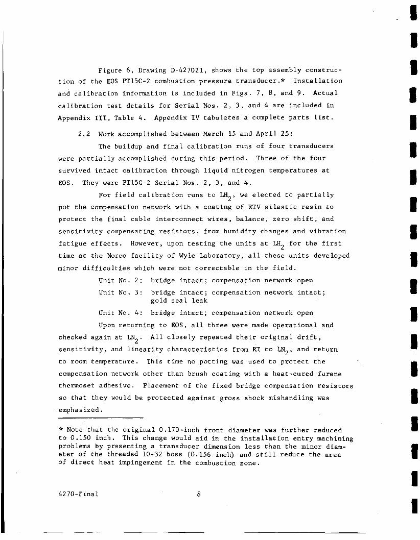
Figure 6 , Drawing D-427021, shows t h e top assembly cons t ruc- t i o n of t h e EOS PT15C-2 combustion p r e s s u r e t ransducer .* I n s t a l l a t i o n
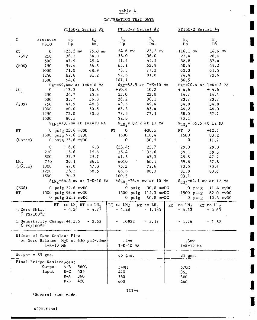
and c a l i b r a t i o n information i s included i n F i g s . 7 , 8 , and 9 . Actua l
c a l i b r a t i o n t e s t d e t a i l s f o r S e r i a l Nos. 2 , 3 , and 4 a r e inc luded i n
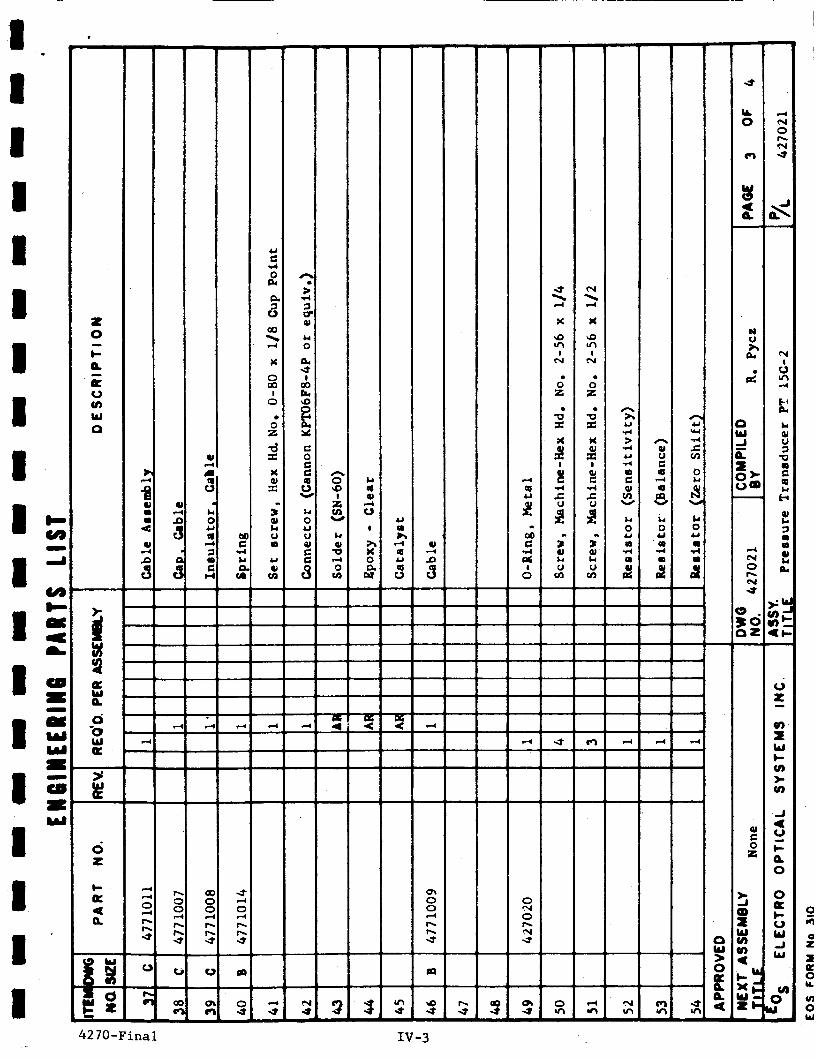
Appendix 111, Table 4 . Appendix I V t a b u l a t e s a complete p a r t s l i s t .
2.2 Work accomplished between March 15 and A p r i l 25:
The buildup and f i n a l c a l i b r a t i o n runs of f o u r t r a n s d u c e r s
were p a r t i a l l y accomplished dur ing t h i s p e r i o d . T h r e e of t h e f o u r
surv ived i n t a c t c a l i b r a t i o n through l i q u i d n i t r o g e n temperatures a t
EOS. They were PT15C-2 S e r i a l Nos. 2 , 3 , and 4 .
For f i e l d c a l i b r a t i o n runs t o LH we e l e c t e d t o p a r t i a l l y
pot t h e compensation network with a c o a t i n g of RTV s i l a s t i c r e s i n t o
p r o t e c t t h e f i n a l cab le in te rconnec t wires , balance , z e r o s h i f t , and
s e n s i t i v i t y compensating r e s i s t o r s , from humidity changes and v i b r a t i o n
f a t i g u e e f f e c t s . However, upon t e s t i n g t h e u n i t s a t LH f o r t h e f i r s t
t i m e a t t h e Norco f a c i l i t y of Wyle Laboratory, a l l t h e s e u n i t s developed
minor d i f f i c u l t i e s which were not c o r r e c t a b l e i n t h e f i e l d .
2’
2
Unit No. 2 : b r i d g e i n t a c t ; compensation network open
Unit No. 3 : br idge i n t a c t ; compensation network i n t a c t ;
Unit N o . 4: b r idge i n t a c t ; compensation network open
Upon r e t u r n i n g t o EOS, a l l t h r e e were made o p e r a t i o n a l and
gold s e a l l eak
checked a g a i n a t LN A l l c l o s e l y repea ted t h e i r o r i g i n a l d r i f t ,
s e n s i t i v i t y , and l i n e a r i t y c h a r a c t e r i s t i c s from RT t o LN and r e t u r n
t o room temperature. This t i m e no p o t t i n g w a s used t o p r o t e c t t h e
compensation network o t h e r than brush c o a t i n g with a hea t -cured furane
thermoset adhesive. Placement of t h e f i x e d br idge compensation r e s i s t o r s
so t h a t they would be p r o t e c t e d a g a i n s t g r o s s shock mishandling w a s
emphasized.
2 ’
2’
Jr Note t h a t the o r i g i n a l 0.170-inch f r o n t diameter w a s f u r t h e r reduced t o 0.150 inch. This change would a i d i n t h e i n s t a l l a t i o n e n t r y machining problems by present ing a t ransducer dimension less than t h e minor diam- e te r of t h e threaded 10-32 boss (0.156 inch) and s t i l l reduce t h e a r e a of d i r e c t hea t impingement i n t h e combustion zone.
42 7 0 - F ina 1 8
I I I 8 4 2 7 0 -F ina 1
rl
9
I4 W
PI 0 H
\
a 0
4 2 7 0 -F ina 1 10
u)
w n a 0
42 7 0 -F inal 11
E , . a
3 t
v) W
S I m
\ /
a 0
42 7 0 -F ina 1 12
8 H
3 la H I4 4 5 3 z 0 H
I4
cn z H
d
8 I I 8 I i 8 I 8 8 8 I 8
8 1 1 R
e
On t h e second s e r i e s of tes ts a t Norco on A p r i l 2 2 , a l l t h r e e
2 u n i t s were s u c c e s s f u l l y c a l i b r a t e d a t LH t empera tures wi thout mishap.
High p res su re helium gas was t h e p r e s s u r i z i n g medium and w a s s imul-
taneous ly in t roduced i n t o t h e dead weight t e s t i n g l i n e s and i n t o the
LH submerged t r ansduce r coolant t u b e , t hen through t h e t r ansduce r i n t o
a f i x e d s t a i n l e s s steel t rapped volume which w a s th readed on t h e 10-32
t h r e a d s , and p r e s s u r e sea led a g a i n s t t h e 0.400-inch- diameter f l a n g e area
(see Fig . 10) .
2
F i n a l checkout a t EOS d i s c l o s e d no i n t e r n a l mois ture condensa-
t i o n problem and complete r e t u r n t o normal room tempera ture c a l i b r a t i o n
cond i t ion . A l l t h r e e t ransducers were thoroughly c l eaned , vacuum d r i e d ,
open tube endings capped and made ready f o r shipment t o t h e c o n t r a c t o r .
2.3 Review of Statement of Work:
I n t h e des ign , f a b r i c a t i o n and t e s t of t h r e e c ryogenic f i l m
cooled p res su re t r ansduce r s , t h e fol lowing s ta tements are made i n a
numerical sequence t o coincide with t h e s p e c i f i c Work Sta tement , i t e m
f o r i t e m :
1.
2 .
3 .
4.
5 .
6 .
7.
4270-Final
The only cons t ruc t ion materials i n c o n t a c t with l i q u i d hydro-
gen a r e s t a i n l e s s s t e e l s (300 series) , n i c k e l s tee l (NiSpanC),
copper, and copper b raz ing a l l o y s .
Sensing element i s t h e p i e z o r e s i s t i v e type s t r a i n gage con-
s t r u c t e d upon h i g h p u r i t y e lementa l s i l i c o n .
A l l t he t ransducers w i l l wi ths tand p r e s s u r e t o 2,000 p s i g
without r e c a l i b r a t i o n and without caus ing permanent change
i n t r ansduce r c h a r a c t e r i s t i c s . Active working diameter of the f lush-mounted t r ansduce r s i s
65 m i l s exposed t o t h e rocke t chamber environment.
Mounting: as descr ibed i n B-500160 drawing (Fig. 6) Pressu re range: 0 t o 1500 p s i g .
Frequency response: f l a t from dc t o 10 kc ; undamped n a t u r a l
frequency by c a l c u l a t i o n i s > 100 kc .
13
WHITEY ..
ALL '/4" STAINLESS PRESSURE SYSTEM FOR STATIC CALIBRATION OF PRESSURE TRANSDUCER AT CRYOGENIC TE M PE RAT U RES; SWAGE LOCK FITTINGS USED; '/s" SYSTEM STARTS AT TRANSDUCER
OIL LEVEL AND GASPRESSURE
*OUTPUT DIRECTLY INTO A S.S. PRESSURE TRAP,
TRANSDUCER.SEAL- J. FLUKE DIFFERENTIAL THREADED ON VOLTMETER MODEL 803 B 34 JC
OFF BY METAL O-RING
*INPUT FROM RCOI -"CONSTANT CURRENT DRIVER"
ON .400" DIA TRANSDUCER FLANGE I
MICRO SYSTEMS INC, PASADENA
POWER SUPPLY TO RCOl LARGE VOLUME DEWAR S.S. "POWER DESIGNS" MODEL 4005 FOR LH, TESTING INPUT:IlSV AC OUTPUT: 28V DC
Jc* NBS TRACEABLE
APPARATUS AND PRESSURE SYSTEM USED AT E.O.S. TRANSDUCER LABORATORY AND AT WYLE L A B . ( N O R C O ) F A C I L I T Y
FIG. 10 LABORATORY AND FIELD TEST APPARATUS AND PRESSURE SYSTEM
427 0 - F i n a l 14
8 8 I IR
8. Combined accuracy: L-H and R = < 1 percent F.S. (a t s t eady
s t a t e temperature cond i t ion ) . 9 . F u l l s c a l e output : > 60 mvdc, unampl i f ied .
. lo . E x c i t a t i o n vol tage: < 10 vdc See i n d i v i d u a l c a l i b r a t i o n
Table 4 , Appendix 111. Constant c u r r e n t : < 15 M a s h e e t , F i g s . 7 , 8 , and 9 and
Bridge impedance: < 1000 ohms
11. Liquid H has hea t of vapor i za t ion = 194.22 Btu / lb , a t one 2 atmosphere pressure ; and
1 2 . By fo rc ing l i q u i d H through t h e u n i t a t g r e a t e r t han com- 2 bus t ion p res su res and a t a ra te of 1 t o 2 g a l l o n s a .TinUte,
t h e f o u r - a c t i v e ann s i l i c o n senso r should su rv ive and not
h e a t up under la rge hea t f l u x e s . Liquid coo lan t must be
passed through the t r ansduce r a t least 30 t o 60 seconds
before combustion i s i n i t i a t e d t o s t a b i l i z e t h e a c t i v e
br idge and f i x e d compensating network. Coolant must con-
t i n u e t o f low a f t e r combustion c u t o f f u n t i l motor cas ing
coo l s below 300°F. 13. Bridge z e r o - d r i f t and br idge s e n s i t i v i t y d r i f t have been
examined a t LN and LH Whereas i t i s p o s s i b l e t o ach ieve
f 1 pe rcen t f u l l s c a l e pe r 100 F a t one cryogenic temperature
(LH~); it seems more p r a c t i c a l t o open t h i s s p e c i f i c a t i o n
s l i g h t l y u n t i l t e s t i n g a t LH becomes more commonplace. See 2 i nd iv idua l c a l i b r a t i o n s h e e t s , F i g s . 7 , 8 , and 9 , and f u r t h e r
remarks under Sect ion D , Recommendations.
0 2 2 '
In summation, t h r e e p re s su re t r ansduce r s have been des igned ,
b u i l t , and t e s t e d f o r opera t ion a t LH cond i t ions t o a s p e c i f i c e n t r y -
mounting geometry and have success fu l ly f u l f i l l e d a l l the b a s i c r equ i r e -
ments of t h e c o n t r a c t Work Statement .
2
15
3 . RECOMMENDATIONS
3 . 1 Mechanical Fea tu res of EOS' PT15C-2 Design
3 . 1 . 1 Although it can b e d e m o n s t r a t e d t h a t a geometry em-
p loying 10-32 th reads i n the mounting a r e a i s not unreasonable t o
achieve, i t i s more r e a l i s t i c t o admit t h a t i t i s a l s o too easy t o
damage these th reads by inadve r t en t over torquing . The LH cooled com-
bus t ion pressure seal must be metal , and t h e n a t u r a l tendency i s t o
ove r t igh ten . We recommend t h a t where poss ib l e a motor chamber i n t e r n a l
threaded boss of 7/16-20 s i z e be used and threaded t o a c o n t r o l l e d
depth, thence t o a small through bore i n t o the combustion chamber.
This would have the r e s u l t of d i s t i n c t improvement i n f i e l d handl ing
and r e l i a b i l i t y of the t ransducer i n s t a l l a t i o n .
2
3 . 1 . 2 The i n t e r n a l cryogenic coo lan t seal and the e x t e r n a l
combustion gas s e a l a r eas should be upgraded t o handle high p res su re
and thermal shock loading beyond the p re sen t scope of the c o n t r a c t .
Present design i s capable of wi ths tanding cryogenic thermal shock and
f u l l s c a l e s t a t i c t e s t p re s su res . Combustion thermal condi t ions , as
they would a f f e c t t he mounting boss a rea , have no t y e t been cons idered .
Mul t ip le chevron (metal, t e f lon, metal) o r K-seals a r e recommended f o r
t e s t i n g . Special s i z e s a r e requi red .
3 . 1 . 3 Diaphragm burnout cond i t ions should be considered,
and escape of combustion gases should be r e s t r i c t e d .
p ressure b a f f l i n g and poss ib l e threaded cable cap c o n s t r u c t i o n should
be reviewed.
Mul t ip l e i n t e r n a l
I 1
1 I D I I 1 I 1
4270-Final 16
3 . 2 Four-active-element S i l i c o n Chip B e a m
3 . 2 . 1 Change i n e l e c t r i c a l r e s i s t a n c e of t he i n d i v i d u a l
e lements of the s i l i c o n ch ip beam wi th from zero t o f u l l s c a l e d i s t r i -
buted pressure on the diaphragm i n d i c a t e s t h a t the compression gages
( p o s i t i o n 2 and 4 ) ( s e e Table 2 , Appendix 111) are c o n t r i b u t i n g only
a small amount i n the way of ou tput .
ove rd r iv ing t h e diaphragm,to r edes ign the s i l i c o n c h i p t o i n c r e a s e the
f u l l scale output t o a t l e a s t 100 mv. Increased output would:
decrease the L-H and R e r r o r band and (2) dec rease thermal e f f e c t s
( s e n s i t i v i t y change and zero d r i f t ) . i n t he gage layout should be i n v e s t i g a t e d t o enhance the output and
reduce the normal b r idge e l e c t r i c a l imbalance.
It should be poss ib l e , wi thout
(1)
Also f u r t h e r geometr ica l changes
3 . 3 Thermal Environment: T rans i en t and Steady S t a t e
3 . 3 . 1 By submerging the t ransducer completely i n cryogenic
f l u i d t o a depth beyond t h e cable cap (see Fig. 6 ) , thermal equ i l ib r ium
i s quick ly achieved, bo th i n t h e difphragm area as w e l l as i n the
e l e c t r i c a l b r idge compensation a rea . I f both a r e a s are not a t i d e n t i -
c a l temperatures nor achieve it simultaneously, t r a n s i e n t thermal out-
pu t could be l a r g e and the e l e c t r i c a l compensation f o r thermal e f f e c t s
e i t h e r slow t o s t a b i l i z e o r never q u i t e achieved. To achieve f a s t
s t a b i l i t y , submersion technique w a s employed. I n terms of f i e l d ( o r
f l i g h t ) t e s t s , t h i s l a t t e r procedure i s probably u n r e a l i s t i c . Relo-
c a t i o n of t he pass ive compensation elements t o t h e l i q u i d cooled
r eg ion of t h e t ransducer i s d e s i r a b l e .
3 . 3 . 2 To achieve a r e a l i s t i c thermal environment e r r o r band
of AS and AZ f o r t h e PT15C-2, t e s t i n g over the e n t i r e c ryogenic t e m -
p e r a t u r e range i s be l i eved necessary. Tests were conducted a t LN
and LH2; however, ambigui t ies i n t h e r e s u l t s (see c a l i b r a t i o n s h e e t s )
i n d i c a t e a need f o r f u r t h e r i n v e s t i g a t i o n i n t h i s a r ea . The problem
he re i s probably r e l a t e d t o the pass ive compensating components used
i n the t h r e e s u b j e c t t ransducers . Fur ther component t e s t i n g should
c o r r e c t t h i s s i t u a t i o n .
2
4270-Final 17
4 . CONCLUSION Modification to Electro-Optical systems' novel combustion pressure
transducer , commerically available in two sizes, the F'T15C-3 for a
minimal access geometry problem, and PT15B-2 (Figs. 11, 1 2 , and 13)
for insertion in an AND 10050-4 boss geometry, such that it could be cooled by LH has resulted in a useful first generation device.
*
2' The results prove the feasibility of the use of a solid state
silicon four-active-arm piezoresistive element, arranged as a Wheatstone
bridge, over a large temperature span, 20°K to > 300 K, with good out-
put for direct recording and within a transducer geometry utilizing
the sensor's inherent small size, fast thermal response, and linear characteristics. These transducers, identified as model F'T15C-2, can
provide the electromechanical means for measuring static (0 to 1500 psig) and dynamic (flat dc to 10 kc) pressures under combustion environment, flush within a liquid rocket cryogenic-cooled motor.
0
* Patent pending
4270-Final 18
. B I 1 I I I I 1 I I I I I u I I M I 1
FIG. 11 EOS DEVEWPED P T 1 5 B COMBUSTION PRESSURE TRANSDUCER W I T H COOLANT FLOW I N OPERATION JUST P R I O R TO FLAME IMPINGEMENT
4 2 7 0 -F ina 1 19
F I G . 12 OXY-HYDROGEN FLAME IMPINGEMENT DIRECTLY ON DIAPHRAGM OF P T 1 5 B COMBUSTION PRESSURE TRANSDUCER
4 2 7 0 -F ina 1 20
, ! I 1 1 I I I I I I 1 I 1 1 I I I 1 I
n t
0-" .
c
4 0 " O
2 h
427 0 -Final 21
e4 m I
W
4270-Fina 1
APPENDIX I LIST OF ABBREVIATIONS
1 I I I I 1 I 1 I 1 I 1 I I 1 I 1 I I
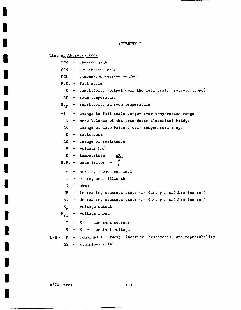
APPENDIX I
L i s t of Abbrevia t ions
T ' N =
C'N =
TU3 =
F.S. =
s = RT =
- - sRT
AS =
z = QZ =
R =
AR =
v = T =
G.F. =
€ =
u - - R =
UP =
DN = -
Eo - - E I N -
I =
v = L-H P R =
ss =
t ens ion gage
compress ion gage
thermo -compression bonded
f u l l s c a l e
s e n s i t i v i t y (output over t he f u l l s c a l e p re s su re range)
room temperature
s e n s i t i v i t y a t room temperature
change i n f u l l s c a l e output over temperature range
ze ro balance of the t ransducer e l e c t r i c a l b r idge
change of ze ro balance over temper a t u r e range
r e s i s t a n c e
change of r e s i s t a n c e
vo l t age (dc)
AR tempera t u r e - R gage f a c t o r = -
s t r a i n , inches p e r inch
micro, one mi l l i on th
ohms
i n c r e a s i n g pressure s t e p s ( a s dur ing a c a l i b r a t i o n run)
decreas ing pressure s t e p s ( a s dur ing a c a l i b r a t i o n run)
vo l t age output
vo l t age i n p u t
K = cons tan t cu r ren t
K = cons tan t vo l tage
combined accuracy; l i n e a r i t y , h y s t e r e s i s , and r e p e a t a b i l i t y
s t a i n l e s s steel
€
1-1
I . I I I I 1 1 I I 8 8 I I 8 m I I I i
4270-Final
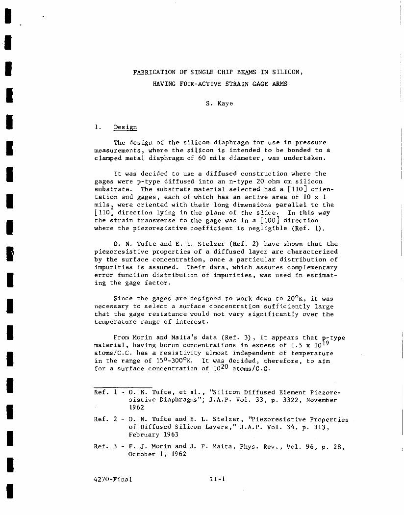
APPENDIX I1
FABRICATION OF SINGLE CHIP BEAMS I N SILICON,
HAVING FOUR-ACTIVE STRAIN GAGE ARMS
Author: Stephen Kaye
FABRICATION OF SINGLE CHIP BEAMS I N SILICON,
HAVING FOUR-ACTIVE STRAIN GAGE ARMS
S. Kaye
1. Design
The des ign of t h e s i l i c o n diaphragm f o r u s e i n p r e s s u r e measurements, where t h e s i l i c o n is in tended t o be bonded t o a clamped m e t a l diaphragm of 60 m i l s d iameter , w a s undertaken.
It w a s decided t o use a d i f f u s e d c o n s t r u c t i o n where t h e gages were p-type d i f fused i n t o an n-type 20 ohm c m s i l i c o n s u b s t r a t e . The s u b s t r a t e m a t e r i a l s e l e c t e d had a [ 1103 or ien- t a t i o n and gages, each of which has a n a c t i v e area of 10 x 1 m i l s , w e r e o r i e n t e d w i t h t h e i r long dimensions p a r a l l e l t o t h e [ l l O ] d i r e c t i o n ly ing i n t h e p lane of t h e s l i ce . t h e s t r a i n t r a n s v e r s e t o t h e gage w a s i n a [ loo] d i r e c t i o n where t h e p i e z o r e s i s t i v e c o e f f i c i e n t i s n e g l i g i b l e (Ref. 1).
I n t h i s way
0. N. T u f t e and E. L. S t e l z e r (Ref. 2) have shown t h a t t h e p i e z o r e s i s t i v e p r o p e r t i e s of a d i f f u s e d l a y e r are c h a r a c t e r i z e d by the s u r f a c e concent ra t ion , once a p a r t i c u l a r d i s t r i b u t i o n of i m p u r i t i e s i s assumed. Their d a t a , which a s s u r e s complementary e r r o r func t ion d i s t r i b u t i o n of i m p u r i t i e s , w a s used i n estimat- i n g t h e gage f a c t o r .
Since t h e gages are designed t o work down t o 20°K, i t w a s necessary t o s e l e c t a sur face c o n c e n t r a t i o n s u f f i c i e n t l y l a r g e t h a t t h e gage r e s i s t a n c e would no t vary s i g n i f i c a n t l y over t h e temperature range of i n t e r e s t .
From Morin and Maita 's d a t a (Ref. 3 ) , i t appears t h a t type m a t e r i a l , having boron concent ra t ions i n excess of 1.5 x 10 atoms/C.C. has a r e s i s t i v i t y almost independent of temperature i n t h e range of 150-300°K. It w a s decided, t h e r e f o r e , t o a i m f o r a s u r f a c e concent ra t ion of 1020 atoms/C.C.
Ref. 1 - 0. N . T u f t e , e t a l . , "S i l icon Dif fused Element Piezore- s i s t i v e Diaphragms"; J.A.P. Vol. 33, p . 3322, November 1962
Ref. 2 - 0. N. T u f t e and E. L. S t e l z e r , ' ' P i e z o r e s i s t i v e P r o p e r t i e s of Diffused S i l i c o n Layers, ' ' J.A.P. Vol. 3 4 , p. 313, February 1963
October 1, 1962 Ref. 3 - F. J. Morin and J. P. Maita , Phys. Rev., Vol. 9 6 , p. 28,
4270-Final 11-1
Under t h e d i f f u s i o n c o n d i t i o n s used , i t was expected t h a t a gauss ian d i s t r i b u t i o n of i m p u r i t i e s would r e s u l t . It was decided t o u s e a 4 j u n c t i o n depth. Using I r v i n ' s d a t a (Ref. 4 ) , it w a s found t h a t t h i s would g i v e a s h e e t r e s i s t a n c e of 40 ohms/square, and hence a gage r e s i s t a n c e of 400 ohms per element.
Using t h e curves i n Ref. 1, a gage f a c t o r of 65 was p r e d i c t e d . 19 Values were a l s o c a l c u l a t e d f o r a s u r f a c e c o n c e n t r a t i o n of 5 x 10 .
This gave a gage r e s i s t a n c e of 800 ohms/square, and a gage f a c t o r of 75.
The s t r e s s d i s t r i b u t i o n expected i n a clamped diaphragm i s such t h a t it i s d e s i r a b l e t o p l a c e two gages c l o s e t o t h e c e n t e r of t h e diaphragm where they w i l l b e i n t e n s i o n , and two c l o s e t o t h e edge w h e r e they w i l l be i n compression. It was decided t o make each element 10 m i l s x 1 m i l , and t h e c o n f i g u r a t i o n shown i n Fig. 2 of t he main tex t of t h i s r e p o r t was used. I n o r d e r t o avoid unwanted s t i f f e n i n g of t h e diaphragm by s o l d e r e d c o n t a c t s , i t w a s decided t o u s e 1 micron of aluminum evaporated and a l l o y e d t o form ohmic contac ts t o t h e a c t i v e elements , and then a t t a c h e x t e r n a l l eads by bonding o r welding t o c o n t a c t pads p laced on approximately the. n e u t r a l a x i s of t h e diaphragm.
2 . Fabr ica t ion Techniques
Table I l i s t s t h e major process s t e p s i n t h e f a b r i c a t i o n of t h e s i l i c o n c h i p s .
Steps 1-27 a r e c a r r i e d o u t on complete s l i c e s each having approximately 60 u n i t s . S teps 28 and 29 are on i n d i v i d u a l u n i t s .
Ref. 4 - J. C. I r v i n , " R e s i s t i v i t y of Bulk S i l i c o n and of Diffused Layers i n S i l i c o n , " B.S.J.T., Vol. X L I , p. 387, March 1962
4270-Final I1 -2
1.
2.
3.
4 .
5.
6 .
7.
8.
9.
10.
11.
12.
13.
14.
15.
16.
17.
18.
19.
20.
21.
TABLE I
Procure s i l i c o n - 20 ohm cm n-type (100) f a c e marked by a f l a t ground on one edge. i l l 8 diameter, .010" t h i c k .
L l l O j o r i e n t a t i o n w i t h S l i c e s 1"
P o l i s h etch - remove approximately 2 m i l s .
Oxidize - 120OoC 2 hours, w e t oxygen.
Coat w i th pho to res i s t and a l i g n mesa p a t t e r n w i t h (100) edge.
Expose, develop, and bake resist .
Etch m e s a s - approximately 1 m i l deep.
Remove p h o t o r e s i s t , c lean , s l i c e , and remove oxide.
Reoxidize - 1200°C 1 hour, w e t oxygen.
Coat w i t h pho to res i s t and r e g i s t e r gage p a t t e r n .
Expose, develop, and bake resist .
Etch oxide.
Remove r e s i s t and clean s l i c e .
Predepos i t boron - 1O5O0C 20 minutes B 0 source
Drive i n - 1050°C 30 minutes.
2 3
Coat w i t h pho to res i s t and r e g i s t e r c o n t a c t p a t t e r n .
Expose, develop, and bake resist.
Etch oxide.
Remove resist and clean s l ice .
Check gage r e s i s t a n c e .
Evaporate aluminum - 1p t h i c k .
Coat w i th pho to res i s t and r e g i s t e r i n v e r t e d c o n t a c t p a t t e r n .
4270-Final I1 -3
2 2 .
23.
24.
25.
26.
27.
28.
29.
Expose, develop, and bake res is t .
Etch aluminum.
Alloy aluminum.
Check gage r e s i s t a n c e .
Mount f o r e t c h i n g f a c e down.
Etch back of s l i c e t o s e p a r a t e and reduce gage t h i c k n e s s t o .0005".
Demount, c l ean , and v i s u a l i n s p e c t .
Bond l eads .
4270-Final I1 -4
1 I 1
4270-Fina 1
APPENDIX I11
TABLES
1 R versus T
2 304 Data
Invar Data
3 NiSpan C Diaphragms
4 Calibration Data (Ser ie s 2 , 3 and 4 )
T VK
2 96
LN2 77
LO2 90
CO2 195
2 96
77
90
CO2 195
296
390.3 356.5
443.4 407.7
499.2 460.6
390.3 356.6
443.0 407.4
Table 1
t
Unbonded Bonded to 304 SS S-G 4 B Gage S-G 4B Gage
Typical res i s tance readings of individual elements of a s i l i c o n beam chip v s . temperature a s read by the Wheatstone bridge method; 1-112 VDC power.
111 -1 4270-Final
Table 2
Typica l bonded s i l i c o n c h i p , i n d i v i d u a l element r e s i s t a n c e changes wi th temperature :
A l l t he above r e s i s t ance elements were pressure cycled while a t the ind ica t ed temperature.
I11 Typica l r e s i s t ance changes wi th temperature be fo re and a f t e r bonding t o Invar constant s t ress beam and when s t r a i n e d t o 1000 microinches.
415.7- 465.8 1 Bonded to 420.8 469.1 Inva r c o n s t r a n t 425.7 472.3 1 s t r e s s beam . 430.9 475.8 436.1 479.1 287.4 337.3 0 m i c r o s t r a i n ' ' ] I 1
0 psig 30.8 mvDC 0 psig 10.5 mvDC CT to LN2 R'1: to LH.
- 4.28 - 1.595
- .0922 - 2.17
.2mv I=K=10 MA
540R 420 3 50 400
111-4 *Several runs made.
4270-Final
RT to LN2 RT to LH2 - 4.13 + 4.63
- 1.76 - 1.82
.3mv I=K=12 MA
85 gms.
5700 365 3 80 440
1
I 42 7 0 -Fina 1
APPENDIX IV PT15C-2 PARTS LIST
1 1 I I 1
c (/1
U C a 4
i i- z m
U - I d
G r(
0 h N U
2 : -1
(II
e
U d
I
a Y Y
.I
U 3 Y
r
I
u
T
h
9 d
. n 4 0 0 U
5 5
s
G d
d a P P) &
cv 0 In *
0 X h X 0
w e
L
U * C
B J
r
W W * - -
-
a 4
0 h N *
13L W
0 m
K s 'I 0
42 7 0 - t i n a I
c. m 4
m IC
- a
T
U C 4 0 fi
a 1 0
Q
'2: X
0 I 0
0 z 1: X 9) X
co
d
E & 0 m Y u m
n A
> U d
4 U d a C 9) m v
& 0 U (ID d 9
2
f l 0 9 I 2 m Y
k 0) Q d 0 Ln
U a h d 6 U 6 0
cp - a W W
- 4
4
w
0 al 0 2
f a 2 UI 0 W
4270-Final IV -3
0 m
n
> d 1 w M 0
rn d I
QD
& e s C 0 C
Y ; & 0 U . u
C 0 u z
a a d
a
W
-2
0 z c 4 Q
a
z a 0 LL
v) 0
- 5 m 9 9
I . 4270-Final I V - 4 I
.
DISTRIBUTION LIST FOR FINAL REPORT
Contract NAS3 -2754
"Liquid Hydrogen Fi lm Cooled P res su re Transducer"
E l e c t r o - o p t i c a l Systems, Inc .
Report i s t o be s e n t d i r e c t l y t o t h e "Rec ip ien t s " marked w i t h an under t h e column headed "Designee" on Pages 1 and 2 only .
Pages 3 through 10, t h e r e p o r t should b e sent t o t h e Technica l L i b r a r i a n of t h e "Recip ien t" w i t h a carbon copy of t h e l e t t e r of t r a n s m i t t a l t o t h e a t t e n t i o n of t h e person named under t h e column Designee". The letter of t r a n s m i t t a l should c o n t a i n the c o n t r a c t
number and complete t i t l e of t h e f i n a l r e p o r t .
The d i s t r i b u t i o n l i s t should be included i n t h e f i n a l r e p o r t as an appendix.
11 11 X On
I 1
COPIES RECIPIENT DESIGNEE
NASA Lewis Research Center 21000 Brookpark Road Cleveland , Ohio 44135'
1
1 Attn : Off ice of Technical Informat ion
NASA Lewis Research Center 21000 Brookpark Road Cleveland, Ohio 44135
1 At tn : Cont rac t ing Off icer
NASA Lewis Research Center 21000 Brookpark Road Cleveland , Ohio 44135
1 At tn : Pa ten t Off ice
NASA Headquarters Washington, D. C. 20546
4 At tn : Mr. Henry Burlage, Jr. Chief , Liquid Propuls ion Systems, RPL
NASA Headquarters Washington, D . C . 20546
Advanced Manned Mission, MTC 1 At tn : M r . Vernon E. J a r a m i l l o
4270, 11-64 1
COPIES RECIPIENT
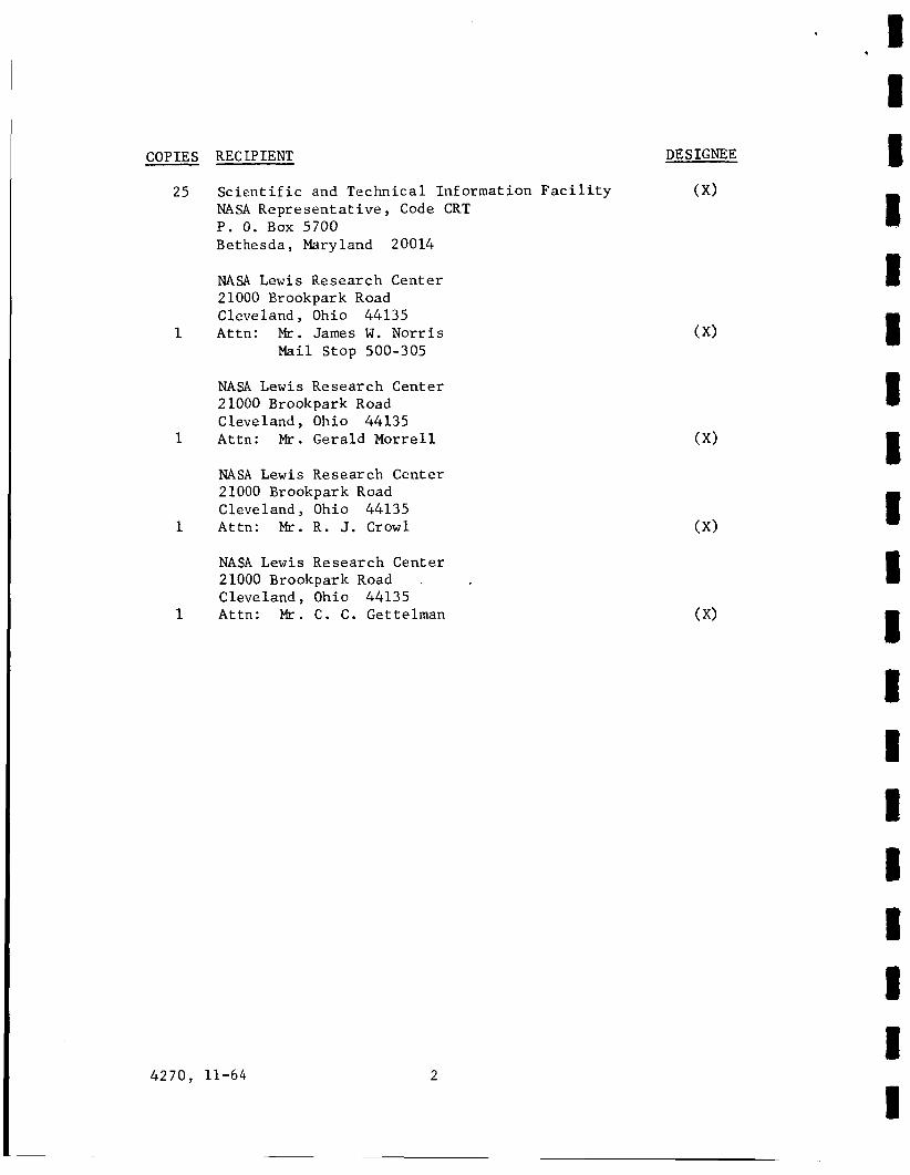
25 Scient i f i c and Technica l Information F a c i l i t y NASA R e p r e s e n t a t i v e , Code CRT P. 0. Box 5700 Bethesda Maryland 20014
NASA L e w i s Research Center 21000 Brookpark Road Cleveland Ohio 44135
1 Attn: M r . James W . Norr i s Mail Stop 500-305
NASA Lewis Research Center 2 1000 Brookpark Road Cleveland Ohio 44135
1 Attn: M I - . Gerald Morre l l
NASA Lewis Research Center 21000 Brookpark Road Cleveland Ohio 44135
1 Attn: Mr. R . J. Crow1
NASA L e w i s Research Center 21000 Brookpark Road .
Cleveland Ohio 44135 1 Attn: M r . C . C . Gettelman
4270, 11-64 2
DE SIGNEE
( X >
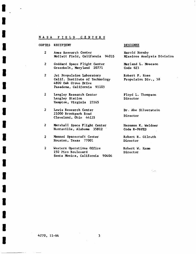
N A S A F I E L D C E N T E R S
COPIES
2
2
2
2
2
2
2
2
RECIPIENT
Ames Research Center Moffett F i e ld , Cal i forn ia 94035
Goddard Space F l i g h t Center Greenbelt, Maryland 20771
Jet Propulsion Laboratory Ca l i f . I n s t i t u t e of Technology 4800 Oak Grove Drive Pasadena, Ca l i fo rn ia 91103
Langley Research Center Langley S ta t ion Hampton, Vi rg in ia 23365
L e w i s Research Center 21000 Brookpark Road Cleveland, Ohio 44135
Marshall Space F l igh t Center Huntsv i l le , Alabama 35812 .
Manned Spacecraft Center Houston, Texas 77001
Western Operations Office 150 Pic0 Boulevard Santa Monica, Cal i forn ia 90406
DE SIGNEE
Harold Hornby Missions Analysis Divis ion
Merland L. Moseson Code 623
Robert F. Rose Propulsion Div., 38
Floyd L. Thompson Direct o r
Dr. Abe S i l v e r s t e i n
Direc t o r
Hermann K. Weidner Code R-P&VED
Robert R. G i l ru th Direc tor
Robert W. Kam Direc t or
4270, 11-64 3
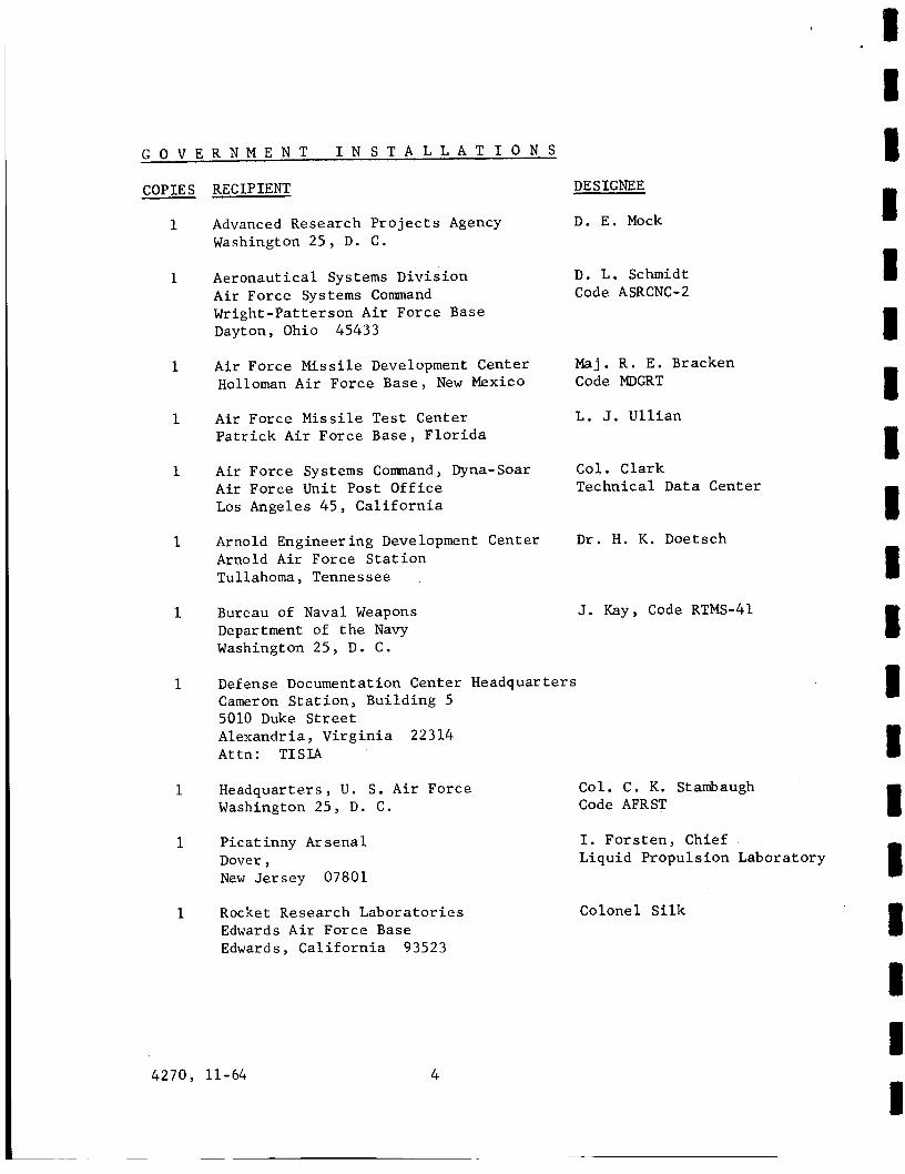
G O V E R N M E N T I N S T A L L A T I O N S
COPIES
1
1
1
1
1
1
1
1
1
1
1
RECIPIENT
Advanced Research P r o j e c t s Agency Washington 25 , D. C .
Aeronaut ical Systems Div i s ion A i r Force Systems Command Wright-Pat terson A i r Force Base Dayton, Ohio 45433
A i r Force Missile Development Center Holloman A i r Force Base, New Mexico
A i r Force Missile Test Center P a t r i c k A i r Force Base, F l o r i d a
A i r Force Systems Command , Dyna-Soar A i r Force Unit Post Of f i ce Los Angeles 45 , C a l i f o r n i a
Arnold Engineering Development Center Arnold A i r Force S t a t i o n Tullahoma, Tennessee
Bureau of Naval Weapons Department of t h e Navy Washington 25, D . C .
DESIGNEE
D. E . Mock
D. L. Schmidt Code ASRCNC-2
Maj. R . E . Bracken Code MDGRT
L . J. U l l i a n
Col. Clark Technical Data Center
D r . H. K . Doetsch
Defense Documentation Center Headquarters Cameron S t a t i on , Building 5 5010 Duke S t r e e t Alexandria , V i rg in i a 22314 Attn: T I S I A
Headquarters , U . S. A i r Force Washington 25, D . C .
P ica t inny Arsenal Dover , New Jersey 07801
J. Kay, Code RTMS-41
Rocket Research Labora to r i e s Edwards A i r Force Base Edwards, C a l i f o r n i a 93523
4270, 11-64 4
I 1 I
Col. C . K. Stambaugh Code AFRST
I. F o r s t e n , Chief Liquid Propuls ion Laboratory
Colonel S i l k
G O V E R N M E N T I N S T A L L A T I O N S
COPIES RECIPIENT DESIGNEE
1 U. S. Atomic Energy Comnission Technical Information Serv ices Box 62 Oak Ridge, Tennessee
1 U. S. Army Missile Command Redstone Arsena l , Alabama 35809
1 U . S. Naval Ordnance Test S t a t i o n China Lake, C a l i f o r n i a 93557
D r . Walter Wharton ~
Code 4 5 1 I
Chief , Missile Propuls ion Div is ion
C P I A
1 Chemical Propuls ion Information Agency N e i l Safeer Johns Hopkins Univers i ty Applied Physics Laboratory 8621 Georgia Avenue S i l v e r Spring, Maryland
4270, 11-64 5
C O M M E R C I A L C O N T R A C T O R S
COPIES RECIPIENT
1 Aerojet-General Corporat ion P. 0. Box 296 Azusa, C a l i f o r n i a
DE S IGNE E
L. F . Kohrs
1 A e r o j e t -General Corporat ion R. S t i f f P . 0. Box Box 1947 Technical L i b r a r y , Bldg 2015, Dept. 2410 Sacramento, 9 , C a l i f o r n i a 95899
1 A e r o je t -Genera l Corporat ion R . D . Wesley P. 0. Box 1947 Technical Library , Bldg . 2015 , Dept . 2410 Sacramento, C a l i f o r n i a 95809
1 Aeronutronic D . A. C a r r i s o n A Division of Ford Motor Company Ford Road Newport Beach, C a l i f o r n i a
1 Aerospace Corporat ion 2400 East E l Segundo Boulevard P. 0 . Box 95085 Los Angeles, C a l i f o r n i a 90045
1 Arthur D . L i t t l e , Inc. Acorn Park Cambridge 40 , Massachusetts
1 Astropower , I n c . , Subsidiary of Douglas A i r c r a f t Company 2968 Randolph Avenue Costa Mesa , C a l i f o r n i a
1 Astrosystems , Inc . 1275 Bloomfield Avenue C a l d w e l l Township , New Jersey
1 A t l a n t i c Research Corporat ion Edsa l l Road and S h i r l e y Highway Alexandria , V i r g i n i a
1 Beech A i r c r a f t Corporat ion Boulder F a c i l i t y Box 631 Boulder , Colorado
4270, 11-64 6
John G. Wilder
Propuls ion Dept. MS-2293
A . C . Tobey
D r . George Moc D i r e c t o r , Research
A . Mendenhall
A. Scurlock
J. H. Rodgers
C O M M E R C I A L C O N T R A C T O R S
COPIES RECIPIENT
1 B e l l Aerosystems Company P. 0. Box 1 Buffalo 5 , New York
1 Bendix Systems Division Bendix Corporation Ann Arbor, Michigan
1 Boeing Company P. 0. Box 3707 S e a t t l e 24, Washington
1 Chrysler Corporation Missile Division Warren, Michigan
1 Curt i s s - W r i g h t Corporat i on Wright Aeronautical Division Woodr idge , New Jersey
DESIGNEE
W. M. Smith
John M. Brueger
J. D. Alexander
John Gates
G. Kelley
1 Douglas A i r c r a f t Company , Inr:. R. W . Hallet Missi le and Space Systems Division Chief Engineer 3000 Ocean Park Boulevard Advanced Space Tech. Santa Monica, Cal i forn ia 90406
1 Fa i r ch i ld S t r a tos Corporation Ai rc ra f t Missiles Division Hagerstown, Maryland
J. S. Kerr
1 General Dynamics/Astronautics Frank Dore Library & Information Services (128-00) P. 0. Box 1128 San Diego, Cal i forn ia 92112
1 General Electric Company Re-Entry Systems Department Box 8555 Phi ladelphia , Pennsylvania 19101
1 General Electric Company F l igh t Propulsion Lab Department Cincinnat i 15 , Ohio
4270, 11-64 7
F . E . Schultz
D. Suichu
C O M M E R C I A L C O N T R A C T O R S
COPIES
1
1
1
1
1
1
1
1
1
1
RECIPIENT
Grumman A i r c r a f t Engineer ing Corp. Be thpage Long I s l a n d , New York
Kidde Aero- Space Div i s ion Walter Kidde and Company, Inc . 675 Main S t r e e t B e l l e v i l l e 9 , New Je r sey
Lockheed C a l i f o r n i a Company 10445 Glen Oaks Boulevard Pacoima, C a l i f o r n i a
Lockheed Missiles and Space Company At tn : Technical Information Center P. 0. Box 504 Sunnyvale, C a l i f o r n i a
Lockheed Pr opu 1 s i o n Company P. 0. Box 111 Redlands, C a l i f o r n i a .
The Marquardt Corporat ion 16555 Sat icoy S t r e e t Box 2013 - South Annex Van Nuys, C a l i f o r n i a 91409
Mart i n Div is ion Martin Mar i e t t a Corporat ion Baltimore 3 , Maryland
Martin Denver Div is ion Martin Marietta Corporat ion Denver, Colorado 80201
McDonnell A i r c r a f t Corporat ion P. 0. Box 6101 Lambert F i e l d , Missouri
DE SIGNEE
Joseph Gavin
R . J. Hanv i l l e D i rec to r of Research Engineer ing
G. D . B r e w e r
Y. C . Lee Power Systems R&D
H. L. Thackwell
Warren P. Boardman, Jr.
John Cala thes (3214)
J. D . Goodle t te Mail A-241
R . A. Herzmark
North American Avia t ion , Inc. H. Storms Space & Information Systems Divis ion Downey, C a l i f o r n i a
4270, 11-64 8
8 . I R C O M M E R C I A L C O N T R A C T O R S
COPIES
1
1
1
1
1
1
1
1
1
1
RECIPIENT
Nor t hrop Corporat ion 1001 E a s t Broadway Hawthorne , C a l i f o r n i a
P r a t t dc Whitney A i r c r a f t Corp. F l o r i d a Research and Development Center P. 0. Box 2691 West P a l m Beach , F l o r i d a 33402
Radio Corporat ion of America As t ro -E lec t ron ic s Div is ion Defense E l e c t r o n i c Products Pr ince ton , New Jersey
Reac t ion Motors Divis ion Thiokol Chemical Corporat ion Denv i l l e , New Je r sey 07832
Repub l i c Avia t ion Corporat ion Farmingdale, Long I s l a n d , New York
Rocketdyne (Library Dept . 586-306) Div is ion of North American Avia t ion 6633 Canoga Avenue Canoga Park, C a l i f o r n i a 91304
Space General Corporat ion 9200 F l a i r Avenue E l Monte, C a l i f o r n i a
Space Technology Labora tor ies Subs id ia ry of Thompson-Ramo-Wooldridge P. 0. Box 95001 Los Angeles 45, C a l i f o r n i a
S tanford Research I n s t i t u t e 333 Ravenswood Avenue Menlo Park, C a l i f o r n i a 94025
TAPCO Divis ion Thompson-Ramo-Wooldridge, Inc . 23555 Eucl id Avenue Cleveland 1 7 , Ohio
DE SIGNEE
W . E . Gasich
R . J. Coar
S. Fa i rweather
Arthur Sherman
D r . W i l l i a m O'Donnell
E. B. MDnteath
C . E . Roth
G . W. Elverum
Thor Smith
P. T. Angel1
4270, 11-64 9
C O M M E R C I A L C O N T R A C T O R S
COPIES RECIPIENT
1 Thiokol Chemical Corporat ion Redstone Div is ion Hun t sv i l l e Alabama
1 United A i r c r a f t Corporat ion Research Labor a t o r i e s 400 Main Street East Har t fo rd , Connecticut 06108
1 United Technology Center 587 Methilda Avenue P. 0. Box 358 Sunnyvale C a l i f o r n i a
1 Vought As t ronau t i c s Box 5907 Dallas 22, Texas
1 Pr ince ton Univers i ty Pr ince ton , New Jersey
4270, 11-64 10
DESIGNEE
John Goodloe
Erle Mart in
B. Abelman
Warren C . Trent
D. Layton
ABSTRACT
A f i l m cooled p res su re t ransducer , designed f o r f l u s h mounting
w i t h i n a rocke t combustion chamber has an a l l s i l i c o n p i e z o r e s i s t i v e
b r idge network.
frequency response.
and w i l l ope ra t e a t LH
and b r idge balance.
It senses s teady s ta te p res su res and has a high f l a t
It is capable of be ing cooled wi th l i q u i d hydrogen,
temperature wi th s m a l l change i n s e n s i t i v i t y
Exposed f r o n t a l a r e a i s only 0.018 square inch. 2