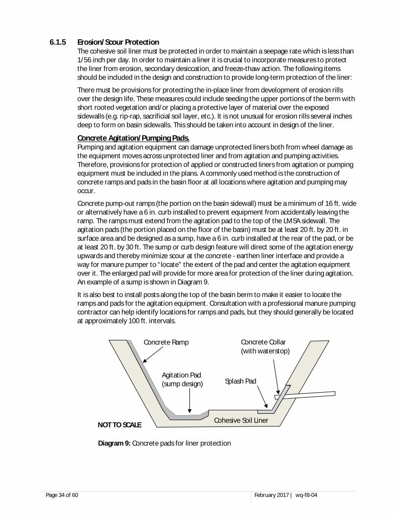
www.pca.state.mn.us Minnesota Pollution Control Agency 651-296-6300 | 800-657-3864 | TTY 651-282-5332 or 800-657-3864 February 2017 | wq-f8-04 Available in alternative formats Liquid Manure Storage Areas MPCA guidelines for design, construction, and operation of all types of liquid manure storage areas Staff photos
Transcript
www.pca.state.mn.us
Minnesota Pollution Control Agency 651-296-6300 | 800-657-3864 | TTY 651-282-5332 or 800-657-3864
February 2017 | wq-f8-04 Available in alternative formats
Liquid Manure Storage Areas MPCA guidelines for design, construction, and operation of all types of liquid manure storage areas
Staff photos
TABLE OF CONTENTS SECTION 1. OVERVIEW ........................................................................................................................... 1
1.1 GOALS OF THIS DOCUMENT ......................................................................................................................................... 1 1.2 DEFINITIONS ............................................................................................................................................................. 2 1.3 PLAN REVIEW AND APPROVAL REQUIREMENTS ................................................................................................................ 4 1.4 “LIMITED RISK LMSA” EXEMPTION FOR SMALL TEMPORARY STORAGE/PROCESSING STRUCTURES ............................................ 4
SECTION 2. SITE SELECTION .................................................................................................................... 7 2.1 LOCATIONAL RESTRICTIONS .......................................................................................................................................... 7 2.2 DRINKING WATER SUPPLY MANAGEMENT AREA (DWSMA) CONSIDERATIONS ................................................................... 13 2.3 WATER TABLE CONSIDERATIONS ................................................................................................................................. 13 2.4 GROUND WATER MONITORING .................................................................................................................................. 13 2.5 AVAILABILITY OF ACREAGE FOR LAND APPLICATION OF MANURE ....................................................................................... 14 2.6 CONSIDERATION OF AIR QUALITY ................................................................................................................................ 14 2.7 WATER SUPPLY CONSIDERATIONS ............................................................................................................................... 14 2.8 SOILS ..................................................................................................................................................................... 14 2.9 FRACTURED BEDROCK - KARST .................................................................................................................................... 14
SECTION 4. STANDARDS FOR ALL TYPES OF LMSAS ................................................................................ 21 4.1 PRE-CONSTRUCTION CONFERENCE .............................................................................................................................. 21 4.2 STORAGE CAPACITY .................................................................................................................................................. 21 4.3 PROFESSIONAL ENGINEER DESIGN ............................................................................................................................... 23 4.4 LMSA LINER PENETRATION PROHIBITION ..................................................................................................................... 23 4.5 SEASONAL WATER TABLE CONTROLS ........................................................................................................................... 24
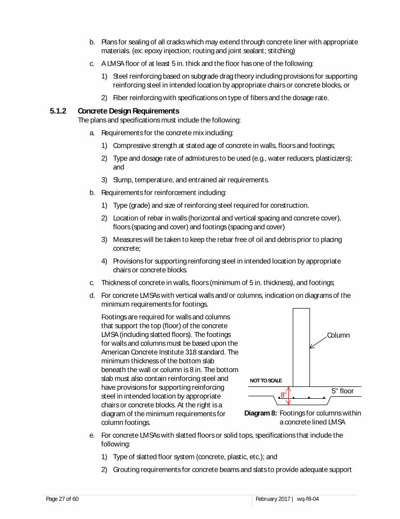
SECTION 5. DESIGN AND CONSTRUCTION STANDARDS FOR CONCRETE LINED LMSAS ............................ 26 5.1 CONCRETE LMSA LINER DESIGN ................................................................................................................................. 26 5.2 CONCRETE LMSA CONSTRUCTION PRACTICES ............................................................................................................... 28
SECTION 6. DESIGN AND CONSTRUCTION STANDARDS FOR EARTHEN LINED LMSAS .............................. 30 6.1 EARTHEN LMSA LINER DESIGN .................................................................................................................................. 30 6.2 EARTHEN LINED LMSA CONSTRUCTION PRACTICES ........................................................................................................ 35
SECTION 7. DESIGN AND CONSTRUCTION STANDARDS FOR GEOSYNTHETIC CLAY LINERS (GCL) .............. 38 7.1 GCL LMSA DESIGN ................................................................................................................................................. 38 7.2 GCL SYNTHETIC LINER CONSTRUCTION PRACTICES ......................................................................................................... 40
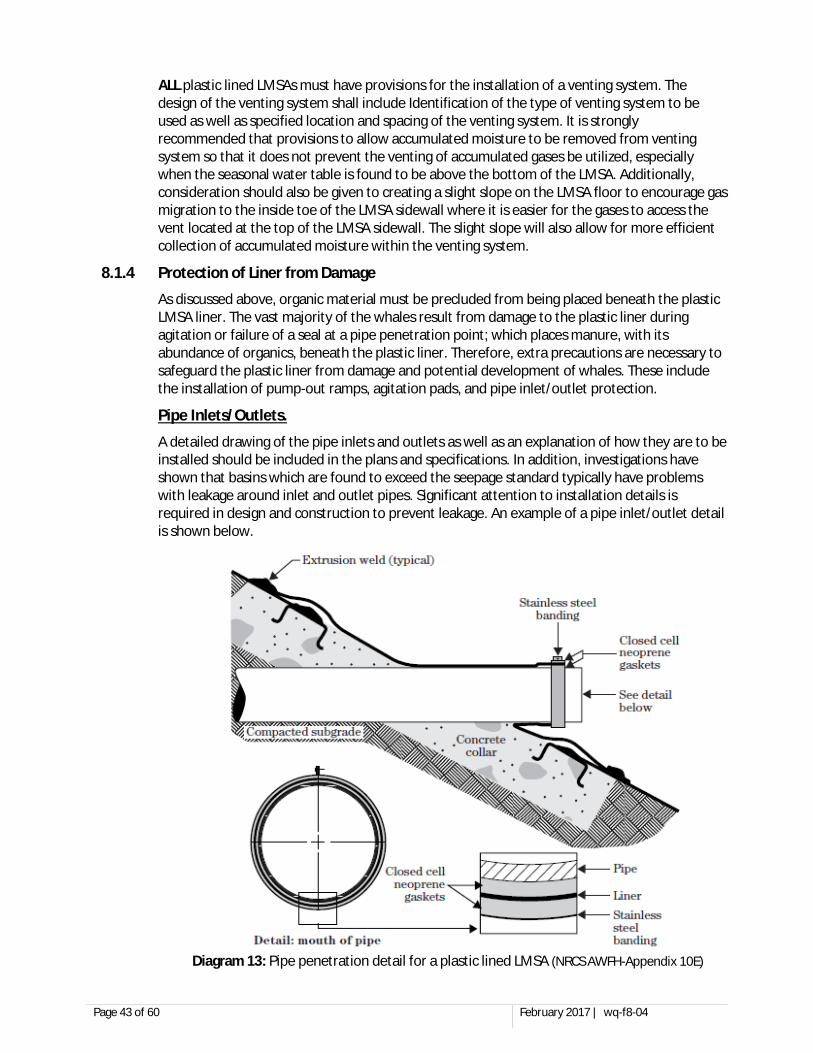
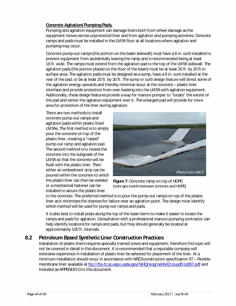
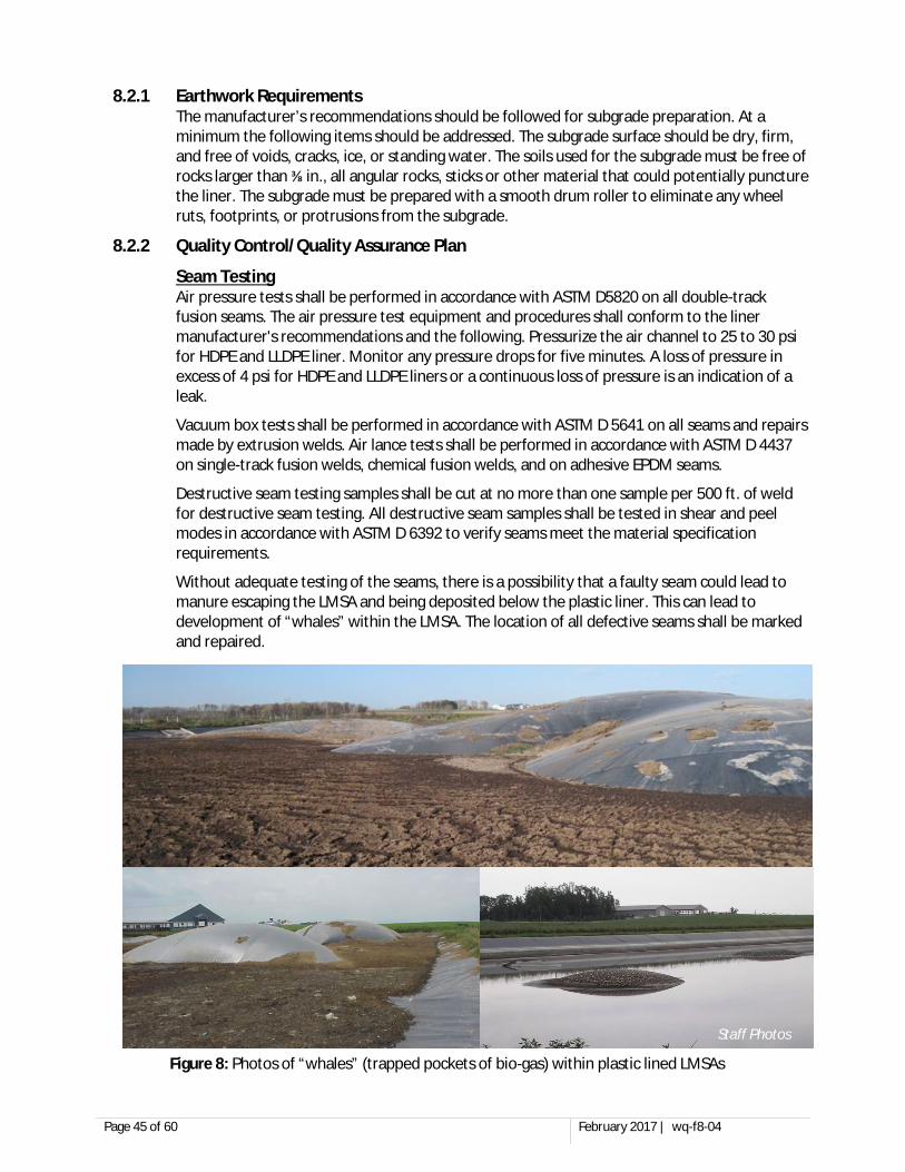
SECTION 8. DESIGN AND CONSTRUCTION STANDARDS FOR PETROLEUM BASED LINERS ........................ 42 8.1 PETROLEUM BASED SYNTHETIC LINER DESIGN ............................................................................................................... 42 8.2 PETROLEUM BASED SYNTHETIC LINER CONSTRUCTION PRACTICES ..................................................................................... 44
SECTION 9. DESIGN AND CONSTRUCTION STANDARDS FOR COMPOSITE AND DUAL LINED LMSAS ......... 46 9.1 COMPOSITE LMSA LINER DESIGN ............................................................................................................................... 46 9.2 DESIGN REQUIREMENTS FOR COMMON COMPOSITE LINED LMSA SYSTEMS ....................................................................... 48 9.3 COMPOSITE LINED LMSA CONSTRUCTION PRACTICES ..................................................................................................... 51
SECTION 10. DESIGN AND CONSTRUCTION STANDARDS FOR ABOVE GROUND LMSAS ........................ 54 10.1 ABOVE GROUND STEEL TANK DESIGN .......................................................................................................................... 54
SECTION 11. DESIGN AND CONSTRUCTION STANDARDS FOR PRE-CAST CONCRETE LINERS .................. 55 11.1 ONE-PIECE PRE-CAST TANK ....................................................................................................................................... 55 11.2 PRE-CAST WALL PANEL LMSA ................................................................................................................................... 55
SECTION 12. DESIGN AND CONSTRUCTION STANDARDS FOR LMSAS WITH OTHER LINERS ................... 56 SECTION 13. OPERATION AND MAINTENANCE OF ALL TYPES OF LMSAS .............................................. 56 SECTION 14. CHANGES TO DESIGN PLANS AND SPECIFICATIONS ......................................................... 57 SECTION 15. NOTIFICATIONS, INSPECTIONS, AND REPORTING ............................................................ 57
15.1 PRE-CONSTRUCTION NOTIFICATION ............................................................................................................................. 57 15.2 CONSTRUCTION INSPECTIONS FOR LMSAS .................................................................................................................... 57 15.3 POST-CONSTRUCTION NOTIFICATION ........................................................................................................................... 58 15.4 CONSTRUCTION REPORTS FOR LMSAS ......................................................................................................................... 58
SECTION 16. CONSTRUCTION STORMWATER ...................................................................................... 59 16.1 FEEDLOT SITES WITH NPDES PERMIT COVERAGE ........................................................................................................... 59 16.2 FEEDLOT SITES WITHOUT NPDES PERMIT COVERAGE ..................................................................................................... 59
SECTION 17. MPCA/CFO REVIEW AND APPROVAL .............................................................................. 59 17.1 LMSA REVIEW CHECKLIST ......................................................................................................................................... 59 17.2 APPROPRIATE CONTENT WITHIN PLANS AND SPECIFICATIONS ............................................................................................ 60
SECTION 18. OTHER SOURCES OF INFORMATION ............................................................................... 60 APPENDIX A Earthen LMSA Liner Pre and Post Construction Testing Summary
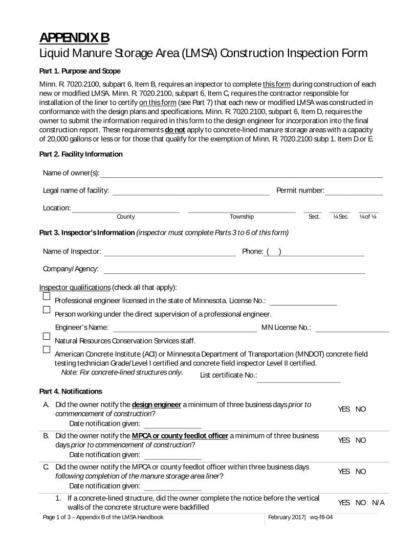
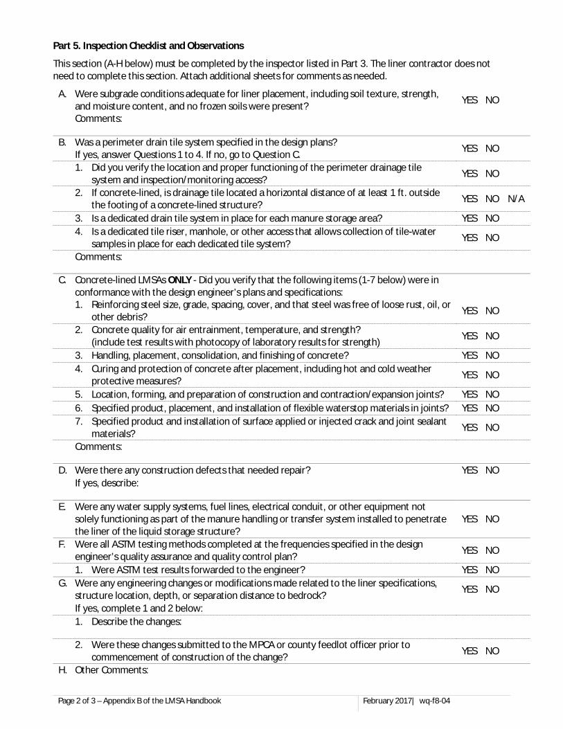
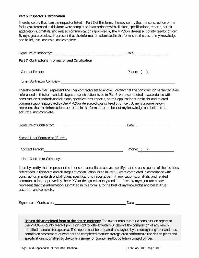
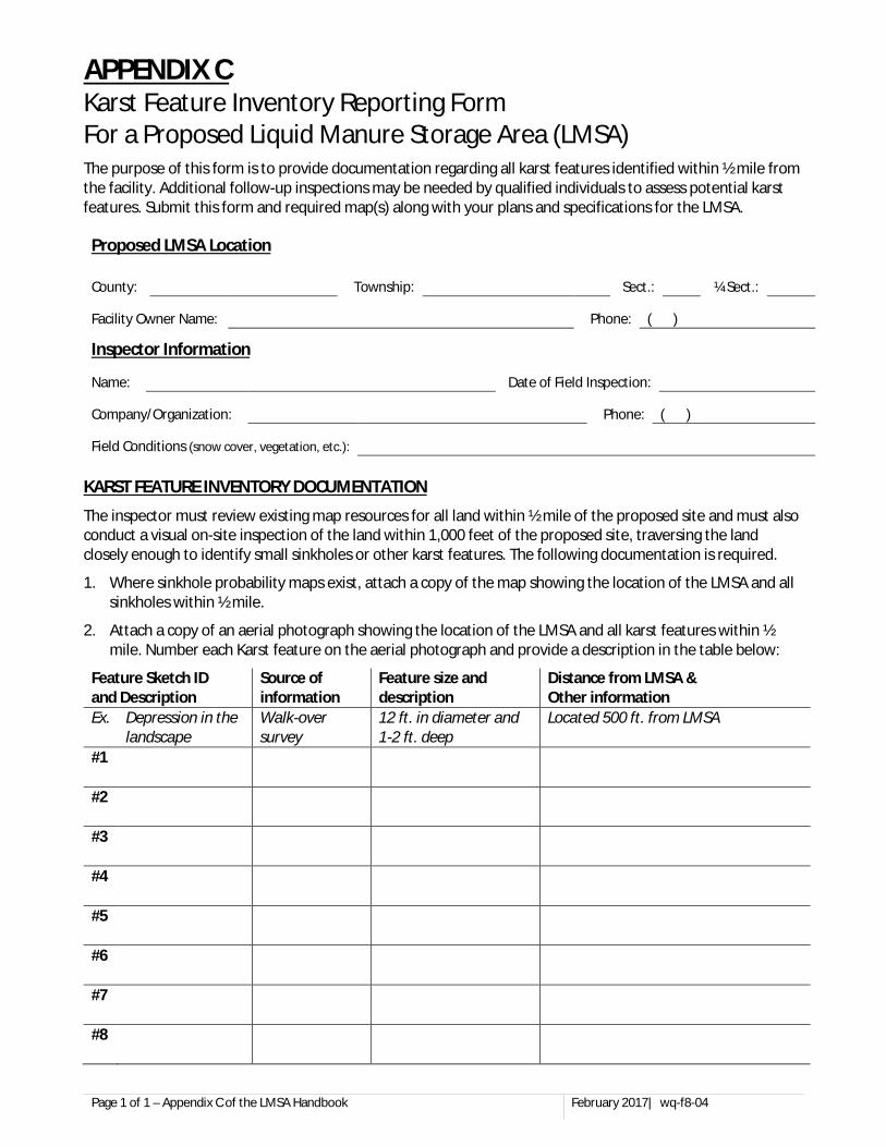
APPENDIX B Construction Inspection Form for Liquid Manure Storage Areas (LMSA) APPENDIX C Karst Feature Inventory Reporting Form For a Proposed Liquid Manure Storage Area (LMSA) APPENDIX D Liquid Manure Storage Area (LMSA) Review Checklist
APPENDIX E Material Specification 595—Geosynthetic Clay Liner
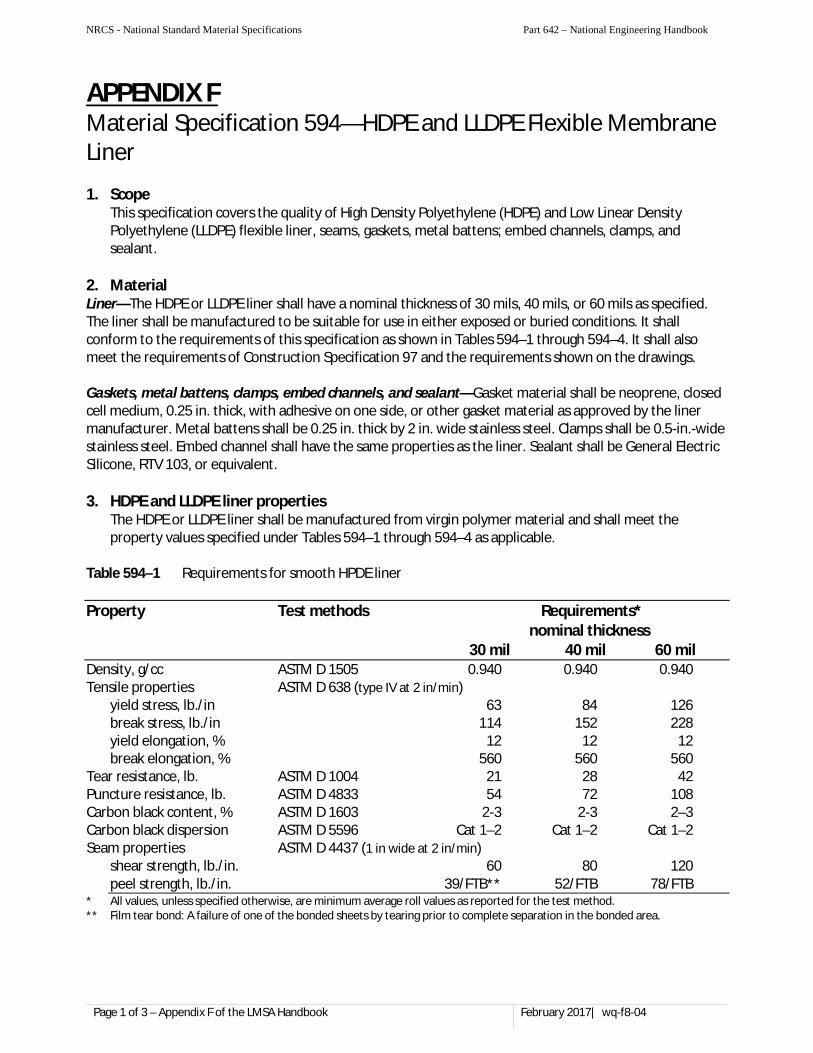
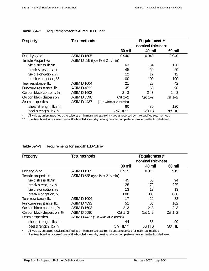
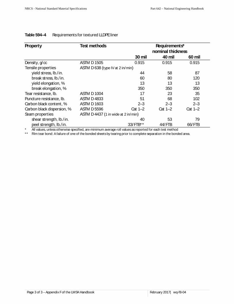
APPENDIX F Material Specification 594—HDPE and LLDPE Flexible Membrane Liner
APPENDIX G Construction Specification 97—Geomembrane Liner
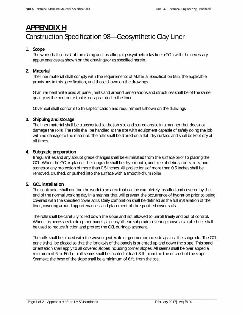
APPENDIX H Construction Specification 98—Geosynthetic Clay Liner
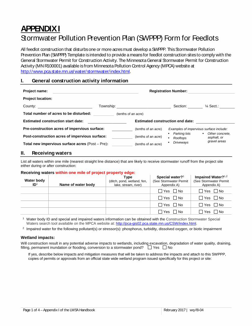
APPENDIX I Stormwater Pollution Prevention Plan (SWPPP) Form for Feedlots
Disclaimer: This document provides guidance for the design, construction, and operation of liquid manure storage areas applicable to a majority of situations. In certain situations the MPCA may allow limited deviations from the guidance within this document. Additionally, the MPCA may require the submittal of more or alternate information when necessary to evaluate compliance with applicable rules, regulations, and design standards.
Page 1 of 60 February 2017 | wq-f8-04
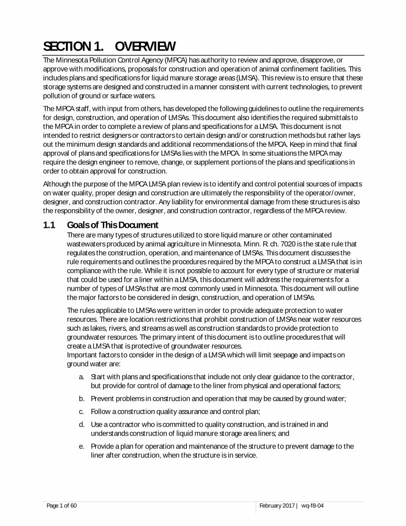
SECTION 1. OVERVIEW The Minnesota Pollution Control Agency (MPCA) has authority to review and approve, disapprove, or approve with modifications, proposals for construction and operation of animal confinement facilities. This includes plans and specifications for liquid manure storage areas (LMSA). This review is to ensure that these storage systems are designed and constructed in a manner consistent with current technologies, to prevent pollution of ground or surface waters.
The MPCA staff, with input from others, has developed the following guidelines to outline the requirements for design, construction, and operation of LMSAs. This document also identifies the required submittals to the MPCA in order to complete a review of plans and specifications for a LMSA. This document is not intended to restrict designers or contractors to certain design and/or construction methods but rather lays out the minimum design standards and additional recommendations of the MPCA. Keep in mind that final approval of plans and specifications for LMSAs lies with the MPCA. In some situations the MPCA may require the design engineer to remove, change, or supplement portions of the plans and specifications in order to obtain approval for construction.
Although the purpose of the MPCA LMSA plan review is to identify and control potential sources of impacts on water quality, proper design and construction are ultimately the responsibility of the operator/owner, designer, and construction contractor. Any liability for environmental damage from these structures is also the responsibility of the owner, designer, and construction contractor, regardless of the MPCA review.
1.1 Goals of This Document There are many types of structures utilized to store liquid manure or other contaminated wastewaters produced by animal agriculture in Minnesota. Minn. R. ch. 7020 is the state rule that regulates the construction, operation, and maintenance of LMSAs. This document discusses the rule requirements and outlines the procedures required by the MPCA to construct a LMSA that is in compliance with the rule. While it is not possible to account for every type of structure or material that could be used for a liner within a LMSA, this document will address the requirements for a number of types of LMSAs that are most commonly used in Minnesota. This document will outline the major factors to be considered in design, construction, and operation of LMSAs.
The rules applicable to LMSAs were written in order to provide adequate protection to water resources. There are location restrictions that prohibit construction of LMSAs near water resources such as lakes, rivers, and streams as well as construction standards to provide protection to groundwater resources. The primary intent of this document is to outline procedures that will create a LMSA that is protective of groundwater resources. Important factors to consider in the design of a LMSA which will limit seepage and impacts on ground water are:
a. Start with plans and specifications that include not only clear guidance to the contractor, but provide for control of damage to the liner from physical and operational factors;
b. Prevent problems in construction and operation that may be caused by ground water;
c. Follow a construction quality assurance and control plan;
d. Use a contractor who is committed to quality construction, and is trained in and understands construction of liquid manure storage area liners; and
e. Provide a plan for operation and maintenance of the structure to prevent damage to the liner after construction, when the structure is in service.
Page 2 of 60 February 2017 | wq-f8-04
1.2 Definitions The following are definitions of terms that will be used throughout this document.
1.2.1 Solid Manure Manure is considered a solid when the manure, has at least a 15% solids content AND can be piled at and maintain a slope of 3:1 (horizontal to vertical).
1.2.2 Liquid Manure Manure that is not solid is considered liquid manure. Frozen liquid manure is not solid manure. When liquid manure undergoes a solids separation process, the manure in the area/structure where the solids separation process occurs shall be considered liquid manure until it is removed from the structure/area and meets the definition of solid manure.
1.2.3 Liquid Manure Storage Area (LMSA) Liquid manure storage area (LMSA) means an area where liquid animal manure (as defined above) and process wastewaters are stored or processed. The following terms that refer to types of manure storage areas, ALL of which are considered LMSAs:
a. Basin – an in-ground structure with sloping sidewalls used to store liquid manure.
b. Pit – an in-ground structure with vertical sidewalls frequently with a slatted top constructed below a barn used to store liquid manure.
c. Lagoon – usually used interchangeably with basin as they refer to the same type of structure. A “true” anaerobic lagoon is different from a basin but such a lagoon has not been constructed in Minnesota (MN) in decades.
d. Anaerobic Digester – a structure that enhances anaerobic digestion of liquid manure in order to create more biogas.
e. Reception or Day Pit/Tank – a structure designed to collect runoff/process wastewater/liquid manure prior to transport to a larger liquid storage structure.
f. Wedge Pit – a structure consisting of a floor sloped with over 1 ft. of fall from front to back with vertical walls/berms on three sides in order to prevent the gravitational migration of the manure placed in the structure.
g. Settling Basin - a structure designed to temporarily impede the movement of “manure contaminated runoff” or “process wastewater” for a limited period of time (usually not to exceed 24 hours) in order to remove suspended solids.
h. Sunny Day Release Basin – a structure that temporarily holds manure contaminated runoff (usually longer than 24 hours) prior to a controlled release to vegetation.
i. Stacking Slab – An area where manure is placed that allows liquid accumulation of more than 1 ft. of depth.
Note: Occasionally this term is used interchangeably with a manure stockpile site. If the material on the “stacking slab” meets the definition of solid manure and the accumulation of liquid on the stacking slab is less than 1 ft. of depth, then this is more appropriately termed a stockpile.
1.2.4 Manure Stockpiles A manure stockpile is a solid manure storage area. Only solid manure can be stockpiled. A manure stockpile site that incorporates a sloped floor to prevent runoff from leaving the stockpile area shall not be considered a LMSA provided the slope of the floor does not allow liquid accumulation that exceeds 1 ft. of depth.
Page 3 of 60 February 2017 | wq-f8-04
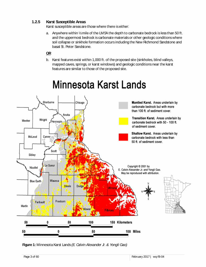
1.2.5 Karst Susceptible Areas Karst susceptible areas are those where there is either:
a. Anywhere within ½ mile of the LMSA the depth to carbonate bedrock is less than 50 ft. and the uppermost bedrock is carbonate materials or other geologic conditions where soil collapse or sinkhole formation occurs including the New Richmond Sandstone and basal St. Peter Sandstone.
OR
b. Karst features exist within 1,000 ft. of the proposed site (sinkholes, blind valleys, mapped caves, springs, or karst windows) and geologic conditions near the karst features are similar to those of the proposed site.
Figure 1: Minnesota Karst Lands (E. Calvin Alexander Jr. & Yongli Gao)
Page 4 of 60 February 2017 | wq-f8-04
1.3 Plan Review and Approval Requirements Minnesota Rules Chapter 7020.2100 Subp. 4. requires that all livestock facility owners submit to the MPCA or County Feedlot Officer (CFO) design plans and specifications for a liquid manure storage area (LMSA) with a permit application, if a permit is necessary, or at least 90 days prior to commencement of construction of a LMSA. The MPCA staff engineers or delegated CFO will conduct a review of the proposed LMSA(s) based upon the factors described in this guidance. Approval to construct and operate a proposed LMSA will be granted in the form of a permit, if a permit is necessary, or via written correspondence if the proposed facility complies with applicable statutes and rules and is approved after review.
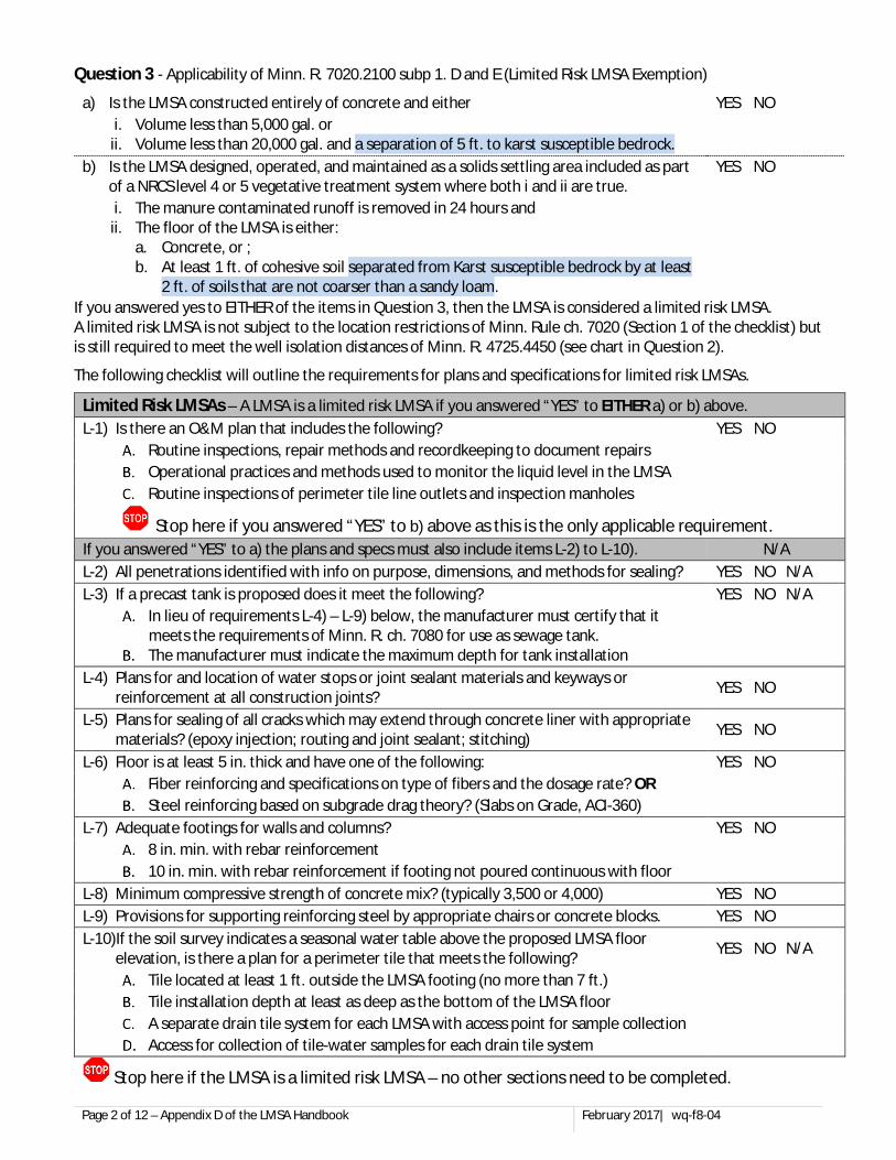
1.4 “Limited Risk LMSA” Exemption for Small Temporary Storage/Processing Structures Minn. R. ch. 7020 regulates all sizes of LMSAs; however, the rule does account for the limited pollution potential from small LMSAs that provide for temporary manure storage or processing. Such small LMSAs that will be referred to as “limited risk LMSAs”. This document will focus on the requirements for larger LMSAs. If you are planning to build/install a limited risk LMSA only the requirements of this item (1.4) are required and the remainder of this document will not discuss how each section would or would not apply to such a structure. You can also refer to the review checklist in APPENDIX D to assist with understanding what information is required.
Minn. R. 7020.2100 subp. 1 D & E provides an exemption to the locational restrictions and most of the design requirements of Minn. R. ch. 7020.2100 for certain LMSAs that provide for temporary storage or processing of waste. This does not mean that there are no regulations pertaining to such structures, nor does it prevent the MPCA from imposing permit conditions it deems necessary to protect the environment, but rather it provides for less rigorous standards for location and construction of this type of LMSA.
There are two instances when a LMSA qualifies for the limited risk LMSA exemption, namely small concrete structures and settling basins used as part of a small scale runoff control system. This section of the document will address all requirements for these structures and the remainder of the document is not applicable to them. Each instance will be addressed separately below.
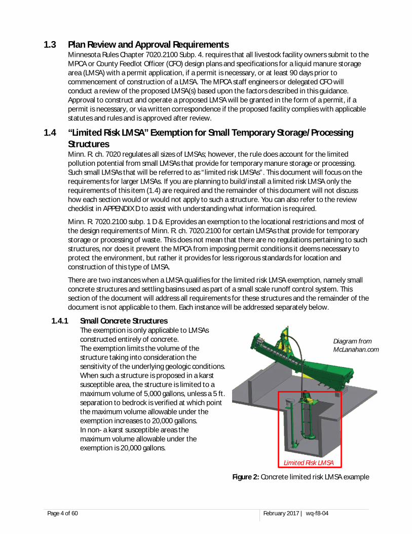
1.4.1 Small Concrete Structures The exemption is only applicable to LMSAs constructed entirely of concrete. The exemption limits the volume of the structure taking into consideration the sensitivity of the underlying geologic conditions. When such a structure is proposed in a karst susceptible area, the structure is limited to a maximum volume of 5,000 gallons, unless a 5 ft. separation to bedrock is verified at which point the maximum volume allowable under the exemption increases to 20,000 gallons. In non- a karst susceptible areas the maximum volume allowable under the exemption is 20,000 gallons.
Diagram from McLanahan.com
Limited Risk LMSA
Figure 2: Concrete limited risk LMSA example
Page 5 of 60 February 2017 | wq-f8-04
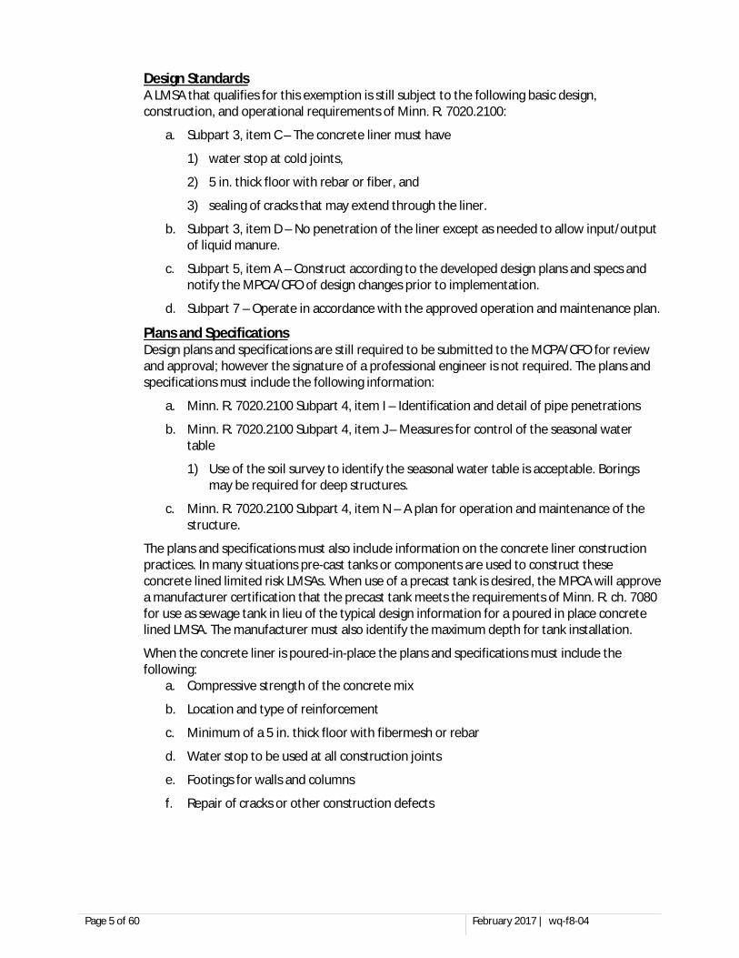
Design Standards A LMSA that qualifies for this exemption is still subject to the following basic design, construction, and operational requirements of Minn. R. 7020.2100:
a. Subpart 3, item C – The concrete liner must have
1) water stop at cold joints,
2) 5 in. thick floor with rebar or fiber, and
3) sealing of cracks that may extend through the liner.
b. Subpart 3, item D – No penetration of the liner except as needed to allow input/output of liquid manure.
c. Subpart 5, item A – Construct according to the developed design plans and specs and notify the MPCA/CFO of design changes prior to implementation.
d. Subpart 7 – Operate in accordance with the approved operation and maintenance plan.
Plans and Specifications Design plans and specifications are still required to be submitted to the MCPA/CFO for review and approval; however the signature of a professional engineer is not required. The plans and specifications must include the following information:
a. Minn. R. 7020.2100 Subpart 4, item I – Identification and detail of pipe penetrations
b. Minn. R. 7020.2100 Subpart 4, item J – Measures for control of the seasonal water table
1) Use of the soil survey to identify the seasonal water table is acceptable. Borings may be required for deep structures.
c. Minn. R. 7020.2100 Subpart 4, item N – A plan for operation and maintenance of the structure.
The plans and specifications must also include information on the concrete liner construction practices. In many situations pre-cast tanks or components are used to construct these concrete lined limited risk LMSAs. When use of a precast tank is desired, the MPCA will approve a manufacturer certification that the precast tank meets the requirements of Minn. R. ch. 7080 for use as sewage tank in lieu of the typical design information for a poured in place concrete lined LMSA. The manufacturer must also identify the maximum depth for tank installation.
When the concrete liner is poured-in-place the plans and specifications must include the following:
a. Compressive strength of the concrete mix
b. Location and type of reinforcement
c. Minimum of a 5 in. thick floor with fibermesh or rebar
d. Water stop to be used at all construction joints
e. Footings for walls and columns
f. Repair of cracks or other construction defects
Page 6 of 60 February 2017 | wq-f8-04
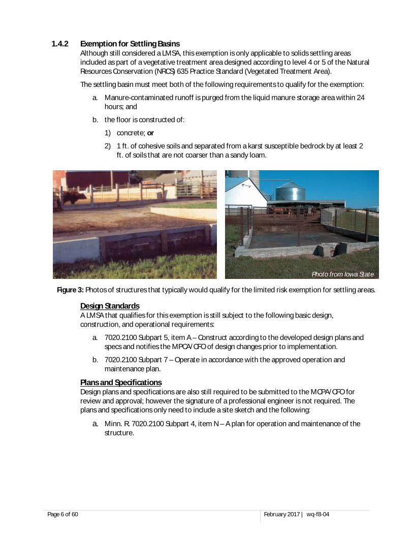
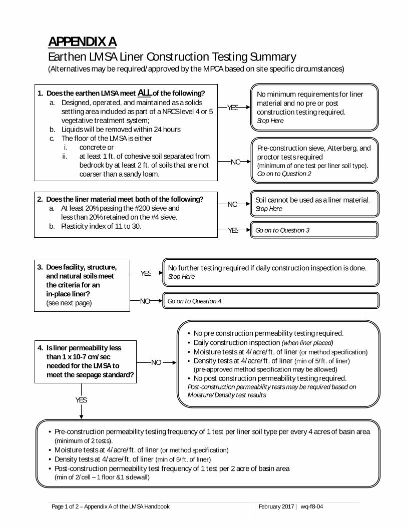
1.4.2 Exemption for Settling Basins Although still considered a LMSA, this exemption is only applicable to solids settling areas included as part of a vegetative treatment area designed according to level 4 or 5 of the Natural Resources Conservation (NRCS) 635 Practice Standard (Vegetated Treatment Area).
The settling basin must meet both of the following requirements to qualify for the exemption:
a. Manure-contaminated runoff is purged from the liquid manure storage area within 24 hours; and
b. the floor is constructed of:
1) concrete; or
2) 1 ft. of cohesive soils and separated from a karst susceptible bedrock by at least 2 ft. of soils that are not coarser than a sandy loam.
Design Standards A LMSA that qualifies for this exemption is still subject to the following basic design, construction, and operational requirements:
a. 7020.2100 Subpart 5, item A – Construct according to the developed design plans and specs and notifies the MPCA/CFO of design changes prior to implementation.
b. 7020.2100 Subpart 7 – Operate in accordance with the approved operation and maintenance plan.
Plans and Specifications Design plans and specifications are also still required to be submitted to the MCPA/CFO for review and approval; however the signature of a professional engineer is not required. The plans and specifications only need to include a site sketch and the following:
a. Minn. R. 7020.2100 Subpart 4, item N – A plan for operation and maintenance of the structure.
Photo from Iowa State
Figure 3: Photos of structures that typically would qualify for the limited risk exemption for settling areas.
Page 7 of 60 February 2017 | wq-f8-04
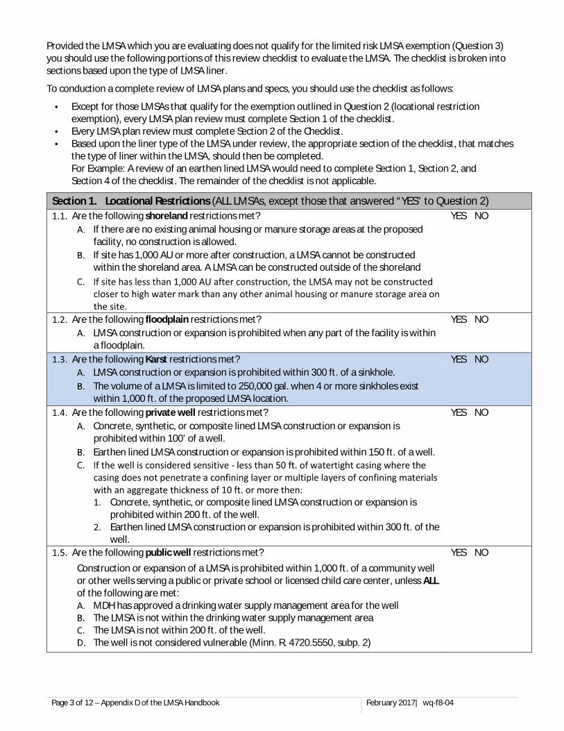
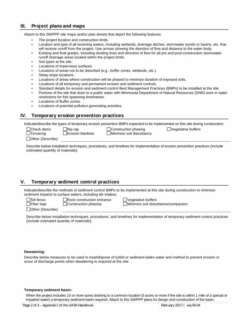
SECTION 2. SITE SELECTION A thorough and accurate site evaluation must be conducted at the location of a proposed LMSA. A preliminary site assessment should be used to evaluate the site from an economic, management and environmental perspective, to minimize the risk of costly engineering modifications and/or problems during or after construction. The following items should be considered while selecting a site:
2.1 Locational Restrictions The following, 2.1.1 to 2.1.6 below, describe locations where construction of a LMSA is prohibited or restricted.
2.1.1 Shoreland Shoreland is defined as:
a. Within 300 ft. of streams, rivers, or creeks or the floodplain boundaries if they extend beyond 300 ft.;
b. Within 1,000 ft. of lakes, ponds, and flowages over 25 acres; or
c. Within 1,000 ft. of type a III, IV, or V wetland if designated shoreland by the DNR or the county (typically over 25 acres)
A facility is considered to be within shoreland if all or part of a feedlot or manure storage area is located within shoreland.
A new animal feedlot or manure storage area cannot be constructed within shoreland.
An existing animal feedlot or manure storage area can expand within the shoreland area if both of the following restrictions are observed.
a. No portion of the expanded animal feedlot or manure storage area is located closer to the ordinary high water mark than any existing portion of the animal feedlot or manure storage area.
b. The animal feedlot or manure storage area does not expand to a capacity of 1,000 AU or more or the manure produced by 1,000 AU or more within the shoreland area.
An existing LMSA within shoreland can be utilized to store or process additional waste provided that there is sufficient volume within the LMSA.
Note: Feedlots or manure storage areas located in shoreland that are currently not in use but have applied for and received an MPCA permit to resume operation, will be considered to be existing feedlots or manure storage areas.
2.1.2 Flood Plain Floodplain is defined as the areas adjoining a watercourse which have been or hereafter may be covered by a large flood known to have occurred generally in Minnesota and reasonably characteristic of what can be expected to occur on an average frequency in the magnitude of the 100 year recurrence interval.
A LMSA cannot be constructed within the floodplain.
Page 8 of 60 February 2017 | wq-f8-04
2.1.3 Wells
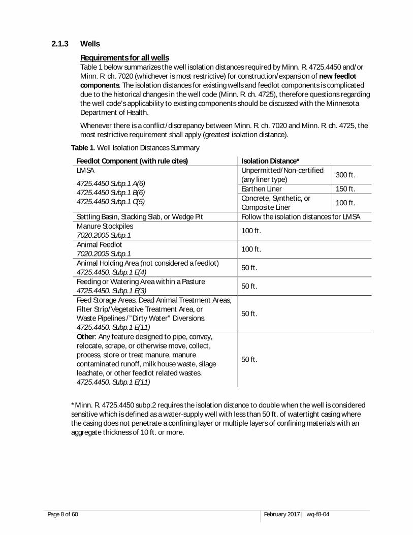
Requirements for all wells Table 1 below summarizes the well isolation distances required by Minn. R. 4725.4450 and/or Minn. R. ch. 7020 (whichever is most restrictive) for construction/expansion of new feedlot components. The isolation distances for existing wells and feedlot components is complicated due to the historical changes in the well code (Minn. R. ch. 4725), therefore questions regarding the well code’s applicability to existing components should be discussed with the Minnesota Department of Health.
Whenever there is a conflict/discrepancy between Minn. R. ch. 7020 and Minn. R. ch. 4725, the most restrictive requirement shall apply (greatest isolation distance).
Table 1. Well Isolation Distances Summary
*Minn. R. 4725.4450 subp.2 requires the isolation distance to double when the well is considered sensitive which is defined as a water-supply well with less than 50 ft. of watertight casing where the casing does not penetrate a confining layer or multiple layers of confining materials with an aggregate thickness of 10 ft. or more.
Unpermitted/Non-certified (any liner type) 300 ft.
Earthen Liner 150 ft. Concrete, Synthetic, or Composite Liner 100 ft.
Settling Basin, Stacking Slab, or Wedge Pit Follow the isolation distances for LMSA Manure Stockpiles 7020.2005 Subp.1 100 ft.
Animal Feedlot 7020.2005 Subp.1 100 ft.
Animal Holding Area (not considered a feedlot) 4725.4450. Subp.1 E(4) 50 ft.
Feeding or Watering Area within a Pasture 4725.4450. Subp.1 E(3) 50 ft.
Feed Storage Areas, Dead Animal Treatment Areas, Filter Strip/Vegetative Treatment Area, or Waste Pipelines /”Dirty Water” Diversions. 4725.4450. Subp.1 E(11)
50 ft.
Other: Any feature designed to pipe, convey, relocate, scrape, or otherwise move, collect, process, store or treat manure, manure contaminated runoff, milk house waste, silage leachate, or other feedlot related wastes. 4725.4450. Subp.1 E(11)
50 ft.
Page 9 of 60 February 2017 | wq-f8-04
Requirements for public/community wells Minn. R. 7020.2005 establishes a 1,000 ft. isolation distance for animal feedlots and manure storage areas (liquid and solid) when the well is:
a. a community water supply well
b. a well serving a public school (Minn. Stat. 120A.05),
c. a well serving a private school (excluding home school sites), or
d. a well serving a licensed child care center.
If all of the following criteria are true the isolation distance can be reduced to 200 ft.:
a. the MDH has an approved DWSMA for the well,
b. the animal feedlot or manure storage area is not located within the DWSMA, and
c. the well is not considered vulnerable (Minn. R. 4720.5550 subp.2).
The requirements pertaining to public/community water supply wells only apply to animal feedlots and/or manure storage areas. This does not apply to feed storage areas, filter strips/vegetative treatment areas, pastures, pipelines, dead animal treatment areas, or features in the “other” category in Table 1.
2.1.4 Karst Locational Restrictions
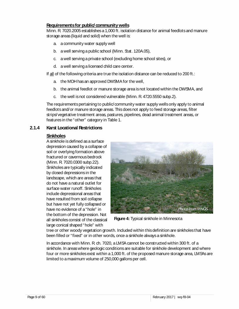
Sinkholes A sinkhole is defined as a surface depression caused by a collapse of soil or overlying formation above fractured or cavernous bedrock (Minn. R. 7020.0300 subp.22). Sinkholes are typically indicated by closed depressions in the landscape, which are areas that do not have a natural outlet for surface water runoff. Sinkholes include depressional areas that have resulted from soil collapse but have not yet fully collapsed or have no evidence of a “hole” in the bottom of the depression. Not all sinkholes consist of the classical large conical shaped “hole” with tree or other woody vegetation growth. Included within this definition are sinkholes that have been filled or “fixed” or in other words, once a sinkhole always a sinkhole.
In accordance with Minn. R. ch. 7020, a LMSA cannot be constructed within 300 ft. of a sinkhole. In areas where geologic conditions are suitable for sinkhole development and where four or more sinkholes exist within a 1,000 ft. of the proposed manure storage area, LMSAs are limited to a maximum volume of 250,000 gallons per cell.
Figure 4: Typical sinkhole in Minnesota
Photo from MNGS
Page 10 of 60 February 2017 | wq-f8-04
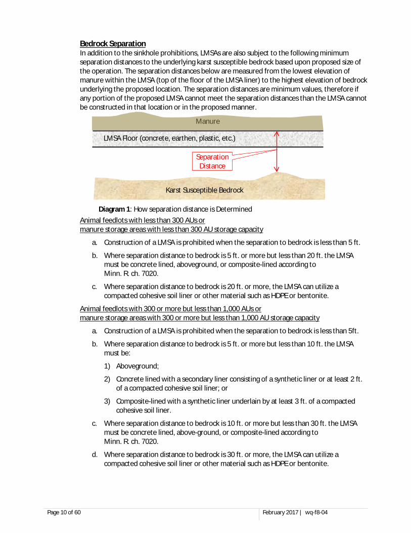
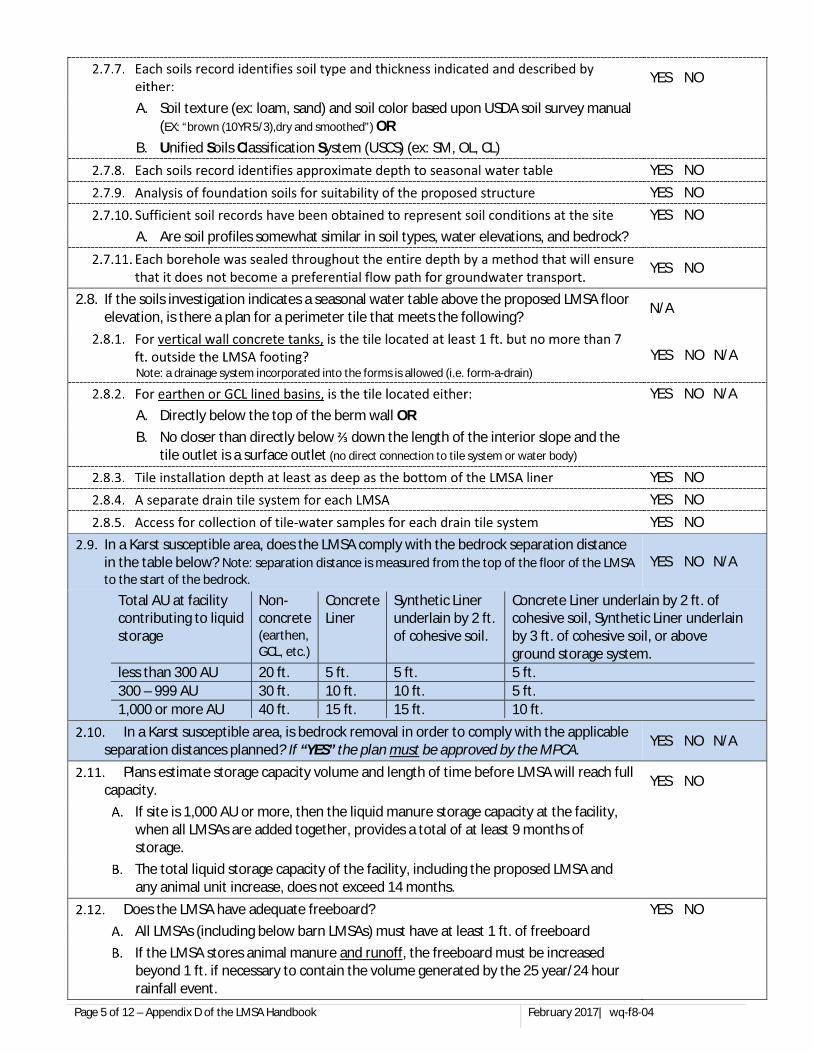
Bedrock Separation In addition to the sinkhole prohibitions, LMSAs are also subject to the following minimum separation distances to the underlying karst susceptible bedrock based upon proposed size of the operation. The separation distances below are measured from the lowest elevation of manure within the LMSA (top of the floor of the LMSA liner) to the highest elevation of bedrock underlying the proposed location. The separation distances are minimum values, therefore if any portion of the proposed LMSA cannot meet the separation distances than the LMSA cannot be constructed in that location or in the proposed manner.
Animal feedlots with less than 300 AUs or manure storage areas with less than 300 AU storage capacity
a. Construction of a LMSA is prohibited when the separation to bedrock is less than 5 ft.
b. Where separation distance to bedrock is 5 ft. or more but less than 20 ft. the LMSA must be concrete lined, aboveground, or composite-lined according to Minn. R. ch. 7020.
c. Where separation distance to bedrock is 20 ft. or more, the LMSA can utilize a compacted cohesive soil liner or other material such as HDPE or bentonite.
Animal feedlots with 300 or more but less than 1,000 AUs or manure storage areas with 300 or more but less than 1,000 AU storage capacity
a. Construction of a LMSA is prohibited when the separation to bedrock is less than 5ft.
b. Where separation distance to bedrock is 5 ft. or more but less than 10 ft. the LMSA must be:
1) Aboveground;
2) Concrete lined with a secondary liner consisting of a synthetic liner or at least 2 ft. of a compacted cohesive soil liner; or
3) Composite-lined with a synthetic liner underlain by at least 3 ft. of a compacted cohesive soil liner.
c. Where separation distance to bedrock is 10 ft. or more but less than 30 ft. the LMSA must be concrete lined, above-ground, or composite-lined according to Minn. R. ch. 7020.
d. Where separation distance to bedrock is 30 ft. or more, the LMSA can utilize a compacted cohesive soil liner or other material such as HDPE or bentonite.
LMSA Floor (concrete, earthen, plastic, etc.)
Karst Susceptible Bedrock
Manure
Separation Distance
Diagram 1: How separation distance is Determined
Page 11 of 60 February 2017 | wq-f8-04
Animal feedlots 1,000 AUs or more or manure storage areas with 1,000 AU or more storage capacity
a. Construction of a LMSA is prohibited when the separation to bedrock is less than 10 ft.
b. Where separation distance to bedrock is 10 ft. or more but less than 15 ft. the LMSA must be:
1) Aboveground;
2) Concrete lined with a secondary liner consisting of a synthetic liner or at least 2 ft. of a compacted cohesive soil liner; or
3) Composite-lined with a synthetic liner underlain by at least 3 ft. of a compacted cohesive soil liner.
c. Where separation distance to the bedrock is 15 ft. or more but less than 40 ft. the LMSA must be concrete lined, above-ground, or composite-lined according to Minn. R. 7020.2100 subp.3 B(2) or (3).
d. Where separation distance to the bedrock is 40 ft. or more, the LMSA can utilize a compacted cohesive soil liner or other material such as HDPE or bentonite.
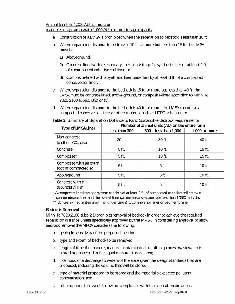
Table 2. Summary of Separation Distance to Karst Susceptible Bedrock Requirements
Type of LMSA Liner Number of animal units (AU) on the entire farm Less than 300 300 – less than 1,000 1,000 or more
Non-concrete (earthen, GCL, etc.)
20 ft. 30 ft. 40 ft.
Concrete 5 ft. 10 ft. 15 ft.
Composite* 5 ft. 10 ft. 15 ft.
Composite with an extra foot of compacted soil 5 ft. 5 ft. 10 ft.
Aboveground 5 ft. 5 ft. 10 ft.
Concrete with a secondary liner** 5 ft. 5 ft. 10 ft.
* A composite-lined storage system consists of at least 2 ft. of compacted cohesive soil below a geomembrane liner and the overall liner system has a seepage rate less than 1/560 inch/day.
** Concrete-lined systems with an underlying 2 ft. cohesive soil liner or geomembrane.
Bedrock Removal Minn. R. 7020.2100 subp.2 D prohibits removal of bedrock in order to achieve the required separation distance unless specifically approved by the MPCA. In considering approval to allow bedrock removal the MPCA considers the following:
a. geologic sensitivity of the proposed location;
b. type and extent of bedrock to be removed;
c. length of time the manure, manure-contaminated runoff, or process wastewater is stored or processed in the liquid manure storage area;
d. likelihood of a discharge to waters of the state given the design standards that are proposed, including the volume that will be stored;
e. type of material proposed to be stored and the material's expected pollutant concentration; and
f. other options that would allow for compliance with the separation distances.
Page 12 of 60 February 2017 | wq-f8-04
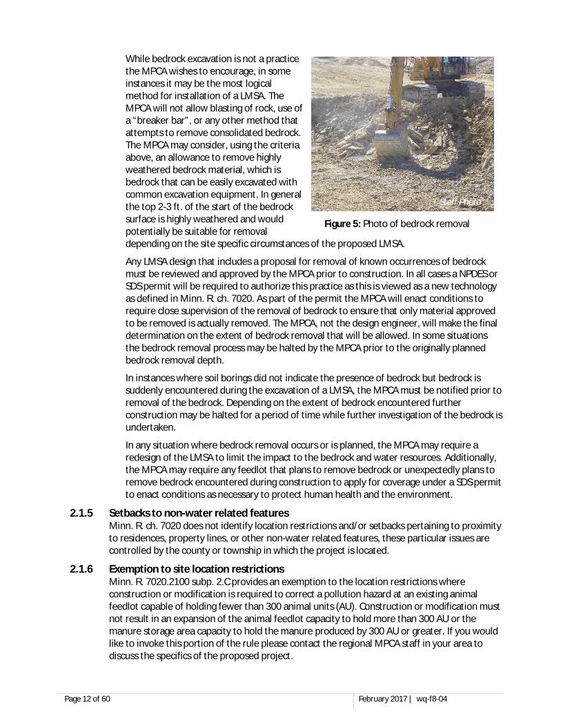
While bedrock excavation is not a practice the MPCA wishes to encourage, in some instances it may be the most logical method for installation of a LMSA. The MPCA will not allow blasting of rock, use of a “breaker bar”, or any other method that attempts to remove consolidated bedrock. The MPCA may consider, using the criteria above, an allowance to remove highly weathered bedrock material, which is bedrock that can be easily excavated with common excavation equipment. In general the top 2-3 ft. of the start of the bedrock surface is highly weathered and would potentially be suitable for removal depending on the site specific circumstances of the proposed LMSA.
Any LMSA design that includes a proposal for removal of known occurrences of bedrock must be reviewed and approved by the MPCA prior to construction. In all cases a NPDES or SDS permit will be required to authorize this practice as this is viewed as a new technology as defined in Minn. R. ch. 7020. As part of the permit the MPCA will enact conditions to require close supervision of the removal of bedrock to ensure that only material approved to be removed is actually removed. The MPCA, not the design engineer, will make the final determination on the extent of bedrock removal that will be allowed. In some situations the bedrock removal process may be halted by the MPCA prior to the originally planned bedrock removal depth.
In instances where soil borings did not indicate the presence of bedrock but bedrock is suddenly encountered during the excavation of a LMSA, the MPCA must be notified prior to removal of the bedrock. Depending on the extent of bedrock encountered further construction may be halted for a period of time while further investigation of the bedrock is undertaken.
In any situation where bedrock removal occurs or is planned, the MPCA may require a redesign of the LMSA to limit the impact to the bedrock and water resources. Additionally, the MPCA may require any feedlot that plans to remove bedrock or unexpectedly plans to remove bedrock encountered during construction to apply for coverage under a SDS permit to enact conditions as necessary to protect human health and the environment.
2.1.5 Setbacks to non-water related features Minn. R. ch. 7020 does not identify location restrictions and/or setbacks pertaining to proximity to residences, property lines, or other non-water related features, these particular issues are controlled by the county or township in which the project is located.
2.1.6 Exemption to site location restrictions Minn. R. 7020.2100 subp. 2.C provides an exemption to the location restrictions where construction or modification is required to correct a pollution hazard at an existing animal feedlot capable of holding fewer than 300 animal units (AU). Construction or modification must not result in an expansion of the animal feedlot capacity to hold more than 300 AU or the manure storage area capacity to hold the manure produced by 300 AU or greater. If you would like to invoke this portion of the rule please contact the regional MPCA staff in your area to discuss the specifics of the proposed project.
Staff Photo
Figure 5: Photo of bedrock removal
Page 13 of 60 February 2017 | wq-f8-04
2.2 Drinking Water Supply Management Area (DWSMA) Considerations LMSAs are designed to limit, not eliminate, the movement of waste and its dissolved constituents into the soil profile. Given that DWSMAs outline areas of recharge groundwater for public water supplies it is prudent to assess the potential for impacts early in the design process. Additional design and construction criteria may be required or, in limited cases, construction may be prohibited if the LMSA is proposed to be located within an approved Minnesota Department of Health DWSMA. The plans and specifications developed for the project must include the following:
a. The location of the animal feedlot, manure storage area, and land application sites on a map of the Minnesota Department of Health approved DWSMA;
b. A copy of the vulnerability assessment of the drinking water supply management area from an approved wellhead protection plan according to part 4720.5210, subparts 2 and 3;
c. A description of the vulnerability of the specific sites for manure storage areas and land application as described in the vulnerability assessment; and
d. A copy of all parts of the drinking water supply management area plan which pertain to animal feedlots, manure storage areas, and land application of manure.
2.3 Water Table Considerations Ground water intrusion can interfere with construction, damage liners, and use capacity in the storage structure. Preliminary site investigations must be done to assess the likelihood of encountering ground water during construction, and designs must include provisions for ground water control during and after construction. The assessment and design must also include consideration of both permanent and seasonal water tables in the vicinity of the system.
2.3.1 Regional Water Table Considerations. The LMSA must be built above the regional water table for the area. Soil investigations at the proposed location should indicate the presence of or potential for ground water in the vicinity of the facility. The static water level recorded on well logs of wells constructed in unconfined aquifers may also provide information on the regional water table elevation. In addition, surface water features in areas with coarse soils may give an indication of depth to shallow regional water tables. The United States Geological Survey quadrangle maps and Natural Resource Conservation Service Soil Surveys are very useful tools to make an initial assessment of the potential for a shallow regional water table.
2.3.2 Seasonal Soil Saturation or Seasonal High Water Table Considerations. Many areas in Minnesota have soils that are seasonally saturated. This shallow, temporary saturation can cause impacts similar to those listed above for regional water tables. If the bottom of the liner is to be constructed below the seasonal high water table (SHWT) a drainage system must be installed to drain ground water away from the structure. Note, however, that in coarse-grained soils with extensive supplies of ground water, standard drain tiling systems may not be effective enough to prevent construction problems or relieve ground water pressures on the liner. Therefore, construction in large deposits of coarse-grained soils below the SHWT or the regional water table may not be permitted.
2.4 Ground Water Monitoring Ground water monitoring may be required around certain new LMSAs. The MPCA will make the determination for the necessity of groundwater monitoring based on the information presented in the plans and specifications and associated documents.
Page 14 of 60 February 2017 | wq-f8-04
2.5 Availability of Acreage for Land Application of Manure Sufficient cropland area must be available to spread the manure nutrients produced by the animals at agronomic rates, and in a manner that is environmentally sound. Please refer to these other MPCA publications pertaining to manure application for more information:
Land Application of Manure: Minimum State Requirements
Applying Manure in Sensitive Areas
Manure Management Plan Requirements and Checklist
2.6 Consideration of Air Quality If possible, the facility should be located so that prevailing winds and air drainage patterns do not create nuisances for neighbors or local public use areas. Prevailing winds should preferably blow odors or air pollutants away from neighbors. Also, in general when wind velocity is low, air “drains” following the same general paths as water. Consider site selection so that “air drainage” paths are not toward a close neighbor. Each site should be thoroughly evaluated to minimize the chance of future nuisance complaints. Air quality monitoring may be required at some facilities with potential for impacts to neighbors from emissions of hydrogen sulfide from manure storage facilities.
Minn. Statute 116.0714 prohibits the construction of new open-air swine LMSAs.
The commissioner of the Pollution Control Agency or a county board shall not approve any permits for the construction of new open air swine basins, except that existing facilities may use one basin of less than 1,000,000 gallons as part of a permitted waste treatment program for resolving pollution problems or to allow conversion of an existing basin of less than 1,000,000 gallons to a different animal type, provided all standards are met.
2.7 Water Supply Considerations A water supply of sufficient quantity and quality must be available to serve the production needs of the facility. A Minnesota Department of Natural Resources (DNR) water appropriation permit is needed when ground water pumping rates exceed 10,000 gallons per day or 1 million gallons per year. Please contact the nearest DNR office for more information about these permits.
2.8 Soils The availability of soils appropriate for use as a liner material is a major economic and practical site limitation in design. This is discussed in greater detail in Section 6.
Sands and gravel deposits (if extensive) can serve as conduits for ground water into the site, and potential pathways out if a significant amount of leakage occurs due to damage to the liner. Extensive deposits of sands and gravels may require installation of an alternative liner material.
2.9 Fractured Bedrock - Karst Some regions, particularly in southeastern Minnesota, may contain areas where fractured bedrock is at a relatively shallow depth. Fractures in bedrock can rapidly transmit both ground water and leakage from damaged or improperly constructed manure storage facilities. In addition to the location prohibitions outlined earlier in this document, consideration should be given to further design practices that provide greater protection to water resources in these areas that are very susceptible to impacts to water resources. More complex conservative or additional design constraints or other requirements as approved by the MPCA Commissioner may also be implemented at the discretion of the design engineer and approved by the MPCA.
SECTION 3. PRE-CONSTRUCTION SITE INVESTIGATION 3.1 Karst Inventory Survey
When a LMSA is proposed to be located within a karst susceptible area a karst inventory survey must be submitted with the design plans and/or permit application. The karst inventory survey consists of three steps that must be completed by an individual experienced with karst geology.
3.1.1 Step 1 - Examine existing maps A complete survey must, at a minimum, examine existing maps and other resources for the evidence of the following karst features within ½ mile of any part of the facility.
a. open and filled sinkholes,
b. closed depressions,
c. known caves,
d. resurgent springs,
e. disappearing streams,
f. karst windows, and
g. blind valleys
The following resources should be utilized when completing this portion of a karst inventory survey:
a. Minnesota karst features database
b. LiDAR maps
c. Aerial photography (current and historical)
d. Sinkhole probability maps (when available)
e. Topographic maps
f. Soil survey
3.1.2 Step 2 – On-site investigation Since the maps do not show all types of karst features and many sinkholes are not mapped, field inspections for possible karst features must supplement information available from the map resources. On-site investigation must be completed when the land surface is visible since a closed depression may not be evident when snow or significant vegetative cover is present on the landscape. As noted elsewhere in this document sinkholes include closed depressional features that have not yet fully collapsed and do not resemble the classic conical sinkhole. The MPCA may require a new on-site investigation if the initial survey was done when conditions were not favorable to adequately identify karst features (i.e. snow cover, dense vegetation). The on-site investigation must cover all land within 1,000 feet of the construction site.
It is also possible that a sinkhole is mapped but no evidence of a sinkhole exists on the landscape. This could be due to a couple of reasons, it may have been filled (which means it is still a sinkhole) or it may be inaccurately mapped. In some cases such a sinkhole discrepancy may play a major part in the design of the LMSA. When this happens and the desire is to confirm/deny the existence of the sinkhole the MPCA will examine the documentation provided and may require further investigation of the sinkhole to confirm or deny that it is a sinkhole.
Page 16 of 60 February 2017 | wq-f8-04
Finally, karst landscape is a dynamic ever changing landscape and therefore on-site investigation must be done as close to the time of construction of the LMSA as possible. It is not possible to definitively set an “expiration” for on-site investigation due to the varying geologic conditions and the nature of karst feature formation. In active karst on-site investigation should be done no more than 1 year ahead of construction of the LMSA. When karst feature formation is not as active (i.e. isolated occurrences) it may be adequate to allow on-site investigation no more than 3 years ahead of construction of the LMSA. In no case should on-site investigation be completed more than 3 years ahead of LMSA construction.
3.1.3 Step 3 - Documentation of Karst Inventory Survey Documentation of the results of the karst inventory survey must be submitted prior to construction with permit application/design plans and must include the following components:
a. A map showing locations of all karst features within ½ mile of the facility (number each feature on an aerial photo/topographic map)
b. Detailed description of each feature shown on the map
c. Copy of maps used in conjunction with the karst feature survey
d. Photographs of features (optional)
e. Name of person completing the survey
f. Date of survey
g. Landscape conditions at time of survey (e.g. snow covered, short vegetation, corn field, etc.)
APPENDIX C to this document is provided to assist with the documentation of the karst inventory survey.
State or county staff may inspect the site or request additional investigation after reviewing the submitted information.
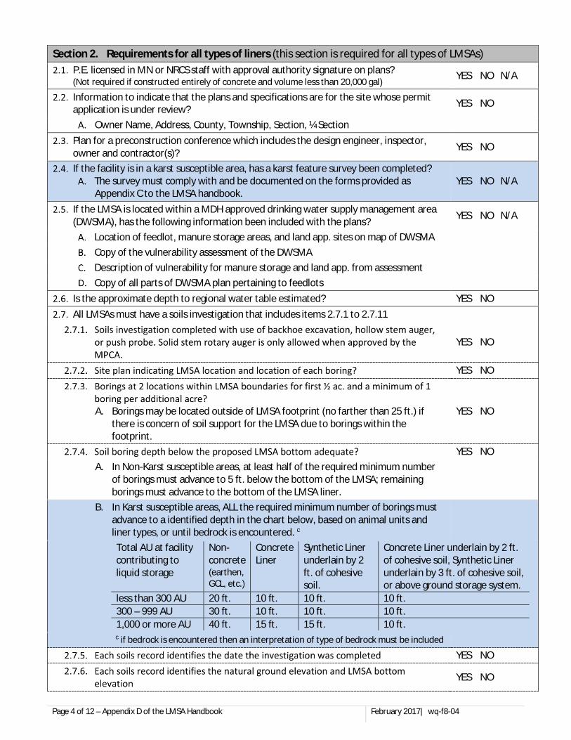
3.2 Soils Investigation The information discussed in this section is applicable to all types of LMSA liners. Each type of LMSA liner may have specific additional requirements presented later in this document, therefore, additional information/restrictions other than those listed here may be applicable based on the type of liner material.
A thorough soils investigation prior to construction is required, and may prevent unexpected delays in construction caused by inadequate site assessment prior to start of construction. The information can be used to help predict whether ground water will cause construction problems, damage to the liner, or flow into the basin. Also the information obtained is useful in identifying whether there is enough cohesive soil available to construct such a liner.
Records of the investigation of the soils at the site are used to determine the depth of the seasonal high water table, presence of saturated soils and/or bedrock, and to identify soil types and soil properties at the proposed LMSA site. A soils investigation is not the same as a soils map or a soils interpretation record. A soils map does not consider areas smaller than three acres in detail and is not adequate for selecting a LMSA site.
Page 17 of 60 February 2017 | wq-f8-04
3.2.1 Type of Equipment Used for Soils Investigations For all methods of soils investigation a description of the soil sample has to be made in increments no greater than 2 ft. and at every change in soil type until at least 5 ft. below the LMSA, or 10 ft. for karst susceptible areas. Soil descriptions are only required at every change in soil type beyond 5 ft. below the LMSA or 10 ft. for karst susceptible areas.
Samples taken for soil property testing to determine adequacy for liner material must be collected individually for each soil type. When the soil type changes, a new, separate sample must be collected and tested. Mixing of different soil types to achieve an average for determining soil properties is not accepted; however a composite sample of similar soil types is allowable.
Methods of soil investigation that mix the sample so that layers as thin as 3 in cannot be distinguished are not accepted.
Solid Stem Rotary Auger A solid stem rotary auger can potentially present a challenge to adequately identify the seasonal water table and/or abrupt soil profile change as required by Minn. R. 7020.2100. Therefore, a rotary auger is only permitted to be used for investigations when prior approval has been obtained from the MPCA.
Hollow Stem Auger/Shelby Tube/Push Probe When using a hollow stem auger, Shelby tube, or push probe, it is crucial that care is taken when extracting the sample. It is recommended that these samples are analyzed and recorded in the field. It is important that the integrity of the sample is not disrupted. Damaged samples may be unsuitable for testing. In the event of damage, new, undamaged samples must be obtained for testing.
When a hollow stem auger is used for a soils investigation a split-spoon sample shall be taken ahead of the auger at every soil type change and at increments that do not exceed 2 ft. The split-spoon samples shall continue until the boring has advanced at least 5 ft. past the lowest depth at which liner material could be placed. Split-spoon sampling at greater depths can occur at design engineer discretion.
Backhoe A backhoe may be used instead of the soil boring equipment to dig a hole to the required depth. The soil analyst can then record the depth to the seasonal high water table and soil types by looking at the soil profile exposed by the excavation. Take the necessary safety precautions to prevent the excavation walls from caving in on the investigator.
Note: Unless specifically noted, the term “boring” refers to the subsurface investigations performed by any of the three methods identified above.
Page 18 of 60 February 2017 | wq-f8-04
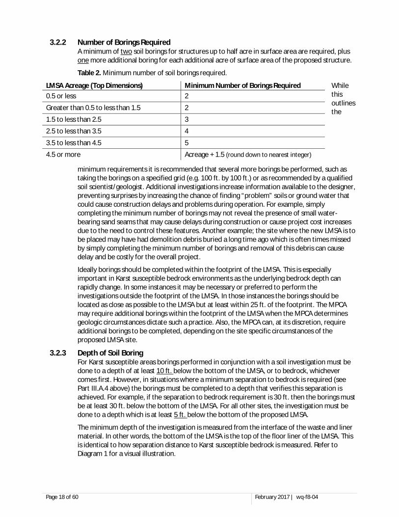
3.2.2 Number of Borings Required A minimum of two soil borings for structures up to half acre in surface area are required, plus one more additional boring for each additional acre of surface area of the proposed structure.
Table 2. Minimum number of soil borings required.
While this outlines the
minimum requirements it is recommended that several more borings be performed, such as taking the borings on a specified grid (e.g. 100 ft. by 100 ft.) or as recommended by a qualified soil scientist/geologist. Additional investigations increase information available to the designer, preventing surprises by increasing the chance of finding “problem” soils or ground water that could cause construction delays and problems during operation. For example, simply completing the minimum number of borings may not reveal the presence of small water-bearing sand seams that may cause delays during construction or cause project cost increases due to the need to control these features. Another example; the site where the new LMSA is to be placed may have had demolition debris buried a long time ago which is often times missed by simply completing the minimum number of borings and removal of this debris can cause delay and be costly for the overall project.
Ideally borings should be completed within the footprint of the LMSA. This is especially important in Karst susceptible bedrock environments as the underlying bedrock depth can rapidly change. In some instances it may be necessary or preferred to perform the investigations outside the footprint of the LMSA. In those instances the borings should be located as close as possible to the LMSA but at least within 25 ft. of the footprint. The MPCA may require additional borings within the footprint of the LMSA when the MPCA determines geologic circumstances dictate such a practice. Also, the MPCA can, at its discretion, require additional borings to be completed, depending on the site specific circumstances of the proposed LMSA site.
3.2.3 Depth of Soil Boring For Karst susceptible areas borings performed in conjunction with a soil investigation must be done to a depth of at least 10 ft. below the bottom of the LMSA, or to bedrock, whichever comes first. However, in situations where a minimum separation to bedrock is required (see Part III.A.4 above) the borings must be completed to a depth that verifies this separation is achieved. For example, if the separation to bedrock requirement is 30 ft. then the borings must be at least 30 ft. below the bottom of the LMSA. For all other sites, the investigation must be done to a depth which is at least 5 ft. below the bottom of the proposed LMSA.
The minimum depth of the investigation is measured from the interface of the waste and liner material. In other words, the bottom of the LMSA is the top of the floor liner of the LMSA. This is identical to how separation distance to Karst susceptible bedrock is measured. Refer to Diagram 1 for a visual illustration.
LMSA Acreage (Top Dimensions) Minimum Number of Borings Required 0.5 or less 2
Greater than 0.5 to less than 1.5 2
1.5 to less than 2.5 3
2.5 to less than 3.5 4
3.5 to less than 4.5 5
4.5 or more Acreage + 1.5 (round down to nearest integer)
Page 19 of 60 February 2017 | wq-f8-04
Be aware that the MPCA can require additional and/or deeper borings if during the review and approval process it is determined that additional information is required. Careful consideration should be given to the amount of borings advanced to the minimum depth so that the site is adequately characterized give the site specific subsurface characteristics. Be aware that having to return to the site for additional deeper investigation can result in an increased cost compared to having performed the deeper borings when the initial investigation was undertaken.
It is recommended that all borings advance to the minimum depths identified above, however the following minimums apply:
Non-Karst susceptible Areas All of the required minimum number of borings, identified in Table 2, must advance to a depth equal to that of the bottom of the LMSA liner. At least half of these borings must advance to a depth at least 5 ft. below the bottom of the LMSA.
Karst Susceptible Areas All of the required minimum number of borings, identified in Table 2, must advance to a depth equal to 10 ft. below the bottom of the LMSA (unless bedrock is encountered). Additionally, all of the borings must advance to a depth that will allow verification of required separation distance based on the type of liner (i.e. 40 ft. for earthen liners).
3.2.4 Information Required for a Complete Soils Investigation for All Liner Types Soils investigations must provide the following information:
a. A site map showing the location of each boring in relation to the proposed LMSA and/or liner material borrow area.
b. Date the borings were performed;
c. Method used to complete the investigation;
d. A boring log diagram indicating the elevation of each soil boring relative to the proposed structure and identification of the elevation of the bottom of the LMSA on each of the boring logs.
e. A description identifying thickness, type and texture of soils, particularly sand and gravel layers. Layers as thin as 3 in. should be described throughout the boring profile. The following methods may be used to provide this description:
1) Comprehensive soil profile which identifies the soil features (e.g. description of soil type and color throughout soil investigation); or
2) List the soils in the profile using the Unified Soils Classification System;
Note: a great resource for soils identification and classification information is Section 3 of the University of Minnesota Subsurface Soil Treatment System manual (septic system manual), available at: http://septic.umn.edu/sstsmanual/index.htm (click on Section 3 link).
f. Depth to saturated soil conditions or actual water level (if encountered);
g. Identification of the depth to the regional water table (estimation if not encountered in the borings). LMSAs cannot be constructed at a depth lower than the regional water table.
h. Evaluation of the potential for groundwater intrusion and damage to the LMSA liner
i. Depth to any seasonal high water tables (SHWT) (e.g. level at which mottling occurs) as interpreted using the soil colors in accordance with the Soil Survey Manual (USDA) or other method (provide reference). Since soil investigations are rarely conducted at the time of wettest soil conditions and shallowest depth to ground water, interpretation of soil colors is required to estimate the shallowest depth where significant amounts of ground water may be encountered.
Ground water found in regional or seasonal high water tables and saturated soils can exert water pressure on the outside walls and floor of below-ground manure storage structures, causing damage to the liner. Water can also seep into the basin, decreasing the available storage capacity. Manure can seep from the basin to the ground water after damage occurs and when ground water levels drop or head increases in the structure. The liner can be damaged whenever the ground water level is higher than liquid level in the structure (typically in the spring and fall). Ground water can also cause major construction delays.
The seasonal high water table (SHWT) can fluctuate considerably throughout the year and from year to year. The level of the shallowest depth to ground water is referred to as either the depth to seasonal saturation, or SHWT. For sites where the soil investigations indicate the presence of a SHWT above the bottom of the structure, the structure design must address potential effects on construction problems and the integrity of the basin liner.
For construction of manure storage structures deeper than the SHWT, precautions must be taken to protect the liner integrity. The SHWT is commonly controlled through the use of a drain tile placed around the perimeter of the structure. Please note that tiling may not be effective in permeable soils that have significant supplies of ground water. Cohesive soil-lined structures will not be approved where ground water level cannot be controlled with a tile drainage system (e.g. extensive deposits of coarse soils).
j. Depth to any encountered bedrock layer, with an interpretation of type of bedrock (e.g. fractured or competent);
In karst susceptible bedrock situations the uppermost bedrock is often highly weathered and is frequently referred to as epikarst. It can be difficult to identify the point at which bedrock exists due to the potential advanced weathering within the epikarst. For purposes of making the determination as to the depth to bedrock, the point at which the soil profile/epikarst contains a majority of rock (less than 50% soil) will be considered the start of bedrock. In some instances the MPCA requests additional soil boring to be undertaken, at which the MPCA is present, to establish the elevation at which bedrock begins.
Additionally, as discussed above, karst susceptible bedrock can include sandstone formations. Sandstone bedrock can be loosely consolidated and is typically overlain by unconsolidated sand particles thereby making it difficult to determine the elevation of the bedrock. In these instances it is recommended, and may be required by the MPCA, to conduct standard penetration testing as part of the subsurface investigation. This data can then be utilized to determine where the bedrock starts even though it may be loosely consolidated.
k. Additional information applicable to the type of liner as identified elsewhere in this document and as allowed by Minn. R. 7020.2100 subp.4.A(10).
Page 21 of 60 February 2017 | wq-f8-04
SECTION 4. STANDARDS FOR ALL TYPES OF LMSAS 4.1 Pre-Construction Conference
All plans and specifications must include a plan for a pre-construction conference that includes the design engineer, contractors, owner, and the individual that will be providing oversight during construction.
4.2 Storage Capacity Storage capacity requirements for LMSAs vary based upon the size of the feedlot which it serves and the type of waste that the LMSA stores. LMSA storage capacity should account for the following factors:
4.2.1 Volume of Manure and Process Wastewater Generated The volume of the LMSA must take into consideration contributions from animal manure, bedding, wastewater, precipitation, and any other sources that contribute waste to the LMSA. The plans and specifications for the LMSA must estimate the amount of manure, bedding, wastewater and precipitation volumes required in the desired storage term and also provide an operating volume for the LMSA. The LMSA storage volume should be compatible with the manure utilization plan. Typically LMSAs are designed for a storage period of 6 to 12 months. The maximum design storage capacity shall not exceed 14 months of manure and process wastewater generation for the components and/or animal numbers listed on the permit.
Minn. R. ch. 7020 does not contain a minimum storage capacity for a LMSA that provides storage for animal manure or animal manure co-mingled with other waste products, unless the LMSA is at a facility with the capacity for 1,000 AU or more.
When the LMSA is constructed at a facility with the capacity for 1,000 AU or more, the minimum liquid manure storage capacity varies based upon the type of waste that is stored.
Manure contaminated runoff or process wastewater storage A LMSA that only collects manure-contaminated runoff or process wastewater is required to have a design capacity for runoff from the 25 year 24 hour storm plus any capacity needed between land application events. This minimum design storage capacity must be maintained at all times. In practice it is advisable to have excess storage volume above this minimum as it can be problematic to immediately land apply waste following a rain event.
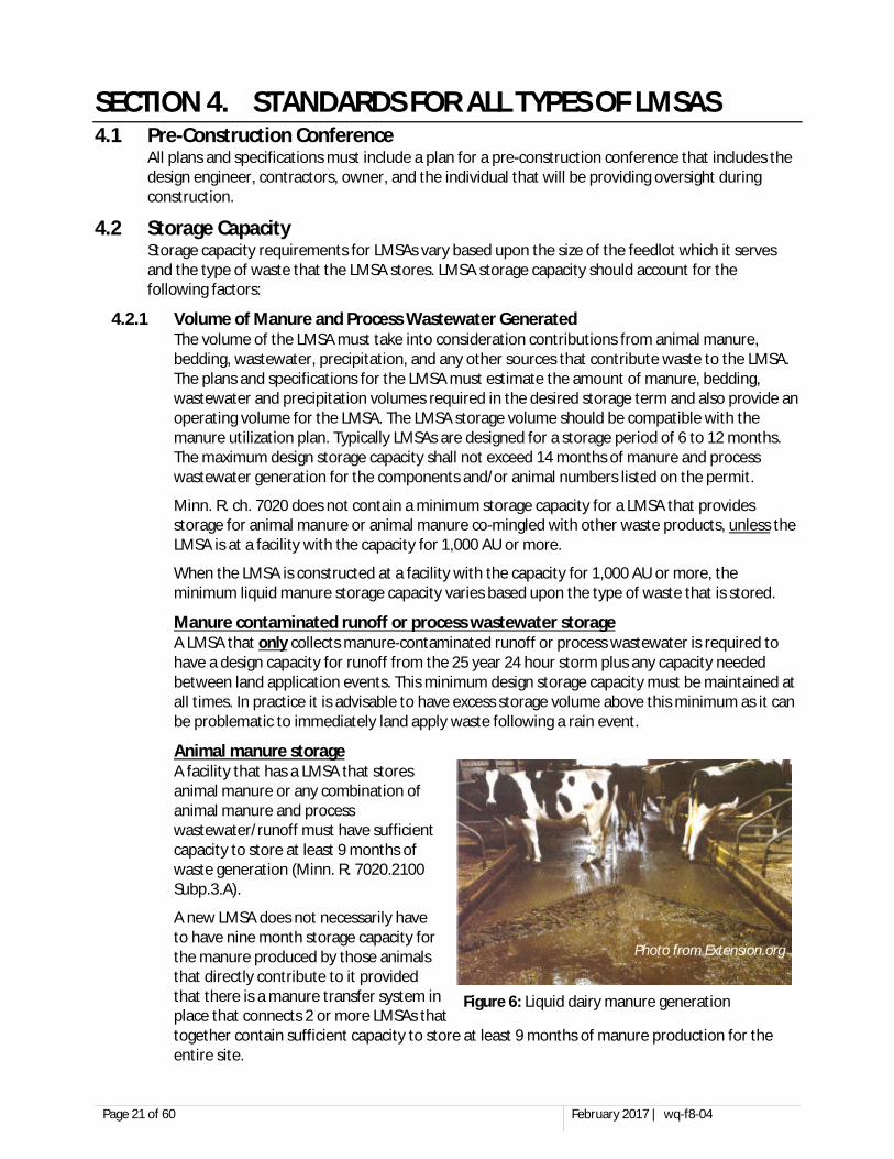
Animal manure storage A facility that has a LMSA that stores animal manure or any combination of animal manure and process wastewater/runoff must have sufficient capacity to store at least 9 months of waste generation (Minn. R. 7020.2100 Subp.3.A).
A new LMSA does not necessarily have to have nine month storage capacity for the manure produced by those animals that directly contribute to it provided that there is a manure transfer system in place that connects 2 or more LMSAs that together contain sufficient capacity to store at least 9 months of manure production for the entire site.
Photo from Extension.org
Figure 6: Liquid dairy manure generation
Page 22 of 60 February 2017 | wq-f8-04
If either an existing feedlot is expanding to a capacity of 1,000 AU or more or an existing feedlot of 1,000 AU or more is proposing an expansion of animal units or manure storage capacity and currently does not have 9 month storage capacity for the entire site, the facility must add sufficient manure storage in order to obtain 9 months manure storage for all animals at the site (existing and additional).
Example: An existing 600 head (840 AU) dairy has one LMSA that has a capacity of 6 months of manure storage. The facility is only looking at adding another freestall barn to house 200 more head (280 AU) for a total of 800 head (1,120 AU). Since the facility is expanding to 1,000 AU or more it is required that 9 months of manure storage is present at the facility, meaning another LMSA would need to be built or the existing LMSA would need to be expanded along with the plan to build an additional barn. The 9 month minimum storage requirement would be based upon 800 head of dairy cows not just the “new” 200 head of dairy cows.
Additionally, when animal waste is co-mingled with manure contaminated runoff or process wastewater, these contributions must also be accounted for with the design calculations for the nine month storage capacity requirement. For example if manure from a dairy with 1,200 AU is stored in a LMSA that also collects runoff from a feed storage area, then nine months of manure volume and nine months of runoff volume need to be included in the design.
4.2.2 Freeboard “Freeboard” is the extra capacity to be maintained in a basin to prevent overflow. The maximum operating level should be clearly marked to allow the operator to empty the basin so as to maintain adequate freeboard. This should include consideration of surface area of basin itself plus any areas from where runoff is directed into the storage system (e.g. open lots).
Minn. R. 7020 requires that all LMSAs have a minimum of 1 ft. of freeboard. If the LMSA collects runoff and co-mingles it with animal manure, the freeboard must be equal to depth required to store the volume of runoff produced by the 25 yr. - 24 hr. storm and at a minimum at least 1 ft. of depth. In other words, all LMSAs must have at least 1 ft. of freeboard but more if the volume of runoff collected exceeds 1 ft. of depth. The freeboard is measured from the lowest point on top of the berm or the lowest point of a designed spillway.
4.2.3 Emergency Spillway. For LMSAs open to precipitation, the design may include provisions for an emergency spillway in the event of an overflow so as to protect the integrity of the berm. If so, maximum liquid depth to maintain “freeboard” to prevent overflow should be calculated from the lowest point of the spillway, not from the top of the berm. In other words, the top of the basin (for design volume purposes) is the lowest point of the spillway. The designer should consider placing the spillway at the point of shortest berm sideslope length to minimize erosion and where any overflow would not directly enter waters of the state.
4.2.4 Unpumpable Volume. Unpumpable volume or sludge buildup must also be accounted for in volume calculations. Unless a sump design is used for pump-out pads a LMSA cannot typically be completely emptied. Also, different types of animal wastes and/or bedding materials, particularly dairy operations with sand and occasionally organic bedding, can lead to sludge accumulation which cannot typically be removed by agitation methods.
Page 23 of 60 February 2017 | wq-f8-04
4.2.5 Freeboard Marker. A freeboard marker is required to mark the maximum liquid depth which still provides adequate freeboard, to prevent overflow. Markings on concrete components are the typical choice for depth marker systems. Devices that penetrate the liner (posts, etc.) need to be identified in the plans and specifications and approved by the MPCA prior to installation. Common examples of depth gauges include:
a. Fixtures mounted to a pump-out ramp/wall such as vertical exposed rebar placed during the concrete pour, or stainless steel or plastic markers;
b. Spray painted lines on the concrete pump-out ramp/wall (make sure lines are visible again following pump-out); or
c. A pole(s) secured below the soil surface along the LMSA sidewall with proper compaction/seal around penetration of the liner material.
4.3 Professional Engineer Design Except were identified below all LMSAs are required to be designed and constructed under the supervision of a professional engineer (P.E.) licensed in the state of Minnesota. The design engineer is required to prepare plans and specifications for the proposed LMSA and provide them to the feedlot owner for submittal to the MPCA for review and approval prior to starting construction of the LMSA. A qualified staff of the NRCS working under NRCS job approval authority will also qualify as a design engineer.
When a LMSA liner is composed entirely of concrete and the structure has a volume of 20,000 gallons or less P.E. design and construction oversight is not required. This exemption from P.E. design and construction oversight does not remove the requirements for design plans and specifications, however. All other requirements remain the same with the only difference being the need for P.E. design and oversight. It is important to note that most of these structures will qualify for the exemption discussed in part 1.4 of this document.
4.4 LMSA Liner Penetration Prohibition Minn. R. 7020.2100 subp3.C prohibits any penetration of the liner of a LMSA except those that solely function as part of the manure/waste handling or transfer system. This prohibition includes such items as penetrations for water and electrical lines. Any allowable penetration must be identified on the design plans and specifications along with the procedures proposed to create a water tight seal at this critical area.
Penetrations of a LMSA liner for water lines is commonly requested when a below barn concrete pit is proposed for liquid manure storage as this can alleviate concerns of water line freeze-up during the winter. As discussed above penetrations of the LMSA liner for water lines are prohibited, however, even though not recommended, the MPCA has allowed/authorized one of the following two methods to be utilized.
4.4.1 Water line penetrates above top of LMSA A water line can penetrate the LMSA liner above the maximum possible liquid level of the LMSA. For example if an overflow/opening is constructed near the top of the wall such that manure storage cannot occur above this level, the concrete wall above this elevation is not considered part of the LMSA liner, as it cannot be utilized for storage of manure, even though it may be constructed concurrently with the wall of the LMSA.
Page 24 of 60 February 2017 | wq-f8-04
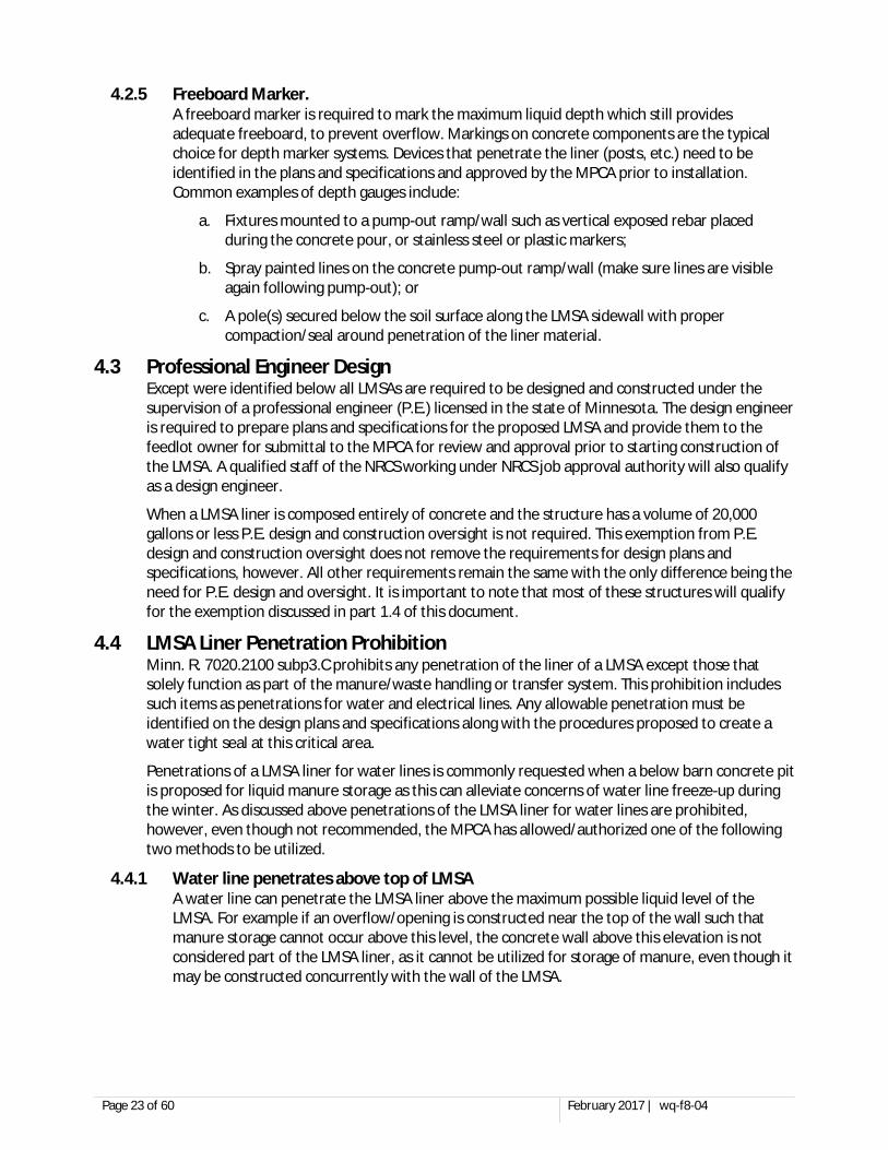
4.4.2 Water Liner Poured into the Wall A water line can be poured into the wall so long as it does not exit into the portion of the LMSA liner that may contact the waste material. In other words, the water line can enter the LMSA liner within the concrete wall but it does not completely penetrate the liner until it exits the wall and can therefore be allowed. A diagram below is provided to illustrate this option.
4.5 Seasonal Water Table Controls The seasonal water table as identified by the required soils investigation must be maintained below the bottom of the liner material. Even if there is no visible water within the soils investigation pits/borings if there is a seasonal water table it must be controlled via artificial drainage. To date the only known effective method for control of seasonal water table is the installation of perforated drain tile around the LMSA. The MPCA does not allow installation of drain tile directly below the LMSA except in extremely limited instances when site specific conditions warrant. When seasonal water table control is required the plans and specifications must incorporate the following items.
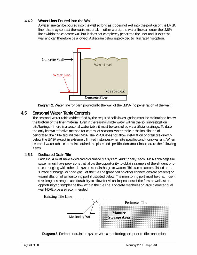
4.5.1 Dedicated Drain Tile Each LMSA must have a dedicated drainage tile system. Additionally, each LMSA’s drainage tile system must have provisions that allow the opportunity to obtain a sample of the effluent prior to co-mingling with other tile systems or discharge to waters. This can be accomplished at the surface discharge, or “daylight”, of the tile line (provided no other connections are present) or via installation of a monitoring port illustrated below. The monitoring port must be of sufficient size, length, strength, and durability to allow for visual inspections of the flow as well as the opportunity to sample the flow within the tile line. Concrete manholes or large diameter dual wall HDPE pipe are recommended.
Existing Tile Line
Perimeter Tile
Manure Storage Area Monitoring Port
Concrete Wall
Waste Level
Concrete Floor
NOT TO SCALE
Water Line
Diagram 3: Perimeter drain tile system with a monitoring port prior to tile connection
Diagram 2: Water line for barn poured into the wall of the LMSA (no penetration of the wall)
Page 25 of 60 February 2017 | wq-f8-04
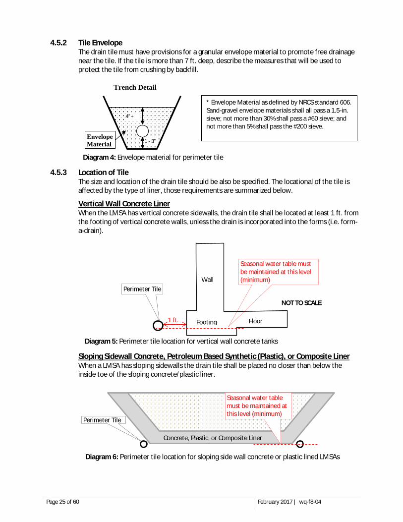
4.5.2 Tile Envelope The drain tile must have provisions for a granular envelope material to promote free drainage near the tile. If the tile is more than 7 ft. deep, describe the measures that will be used to protect the tile from crushing by backfill.
4.5.3 Location of Tile The size and location of the drain tile should be also be specified. The locational of the tile is affected by the type of liner, those requirements are summarized below.
Vertical Wall Concrete Liner When the LMSA has vertical concrete sidewalls, the drain tile shall be located at least 1 ft. from the footing of vertical concrete walls, unless the drain is incorporated into the forms (i.e. form-a-drain).
Sloping Sidewall Concrete, Petroleum Based Synthetic (Plastic), or Composite Liner When a LMSA has sloping sidewalls the drain tile shall be placed no closer than below the inside toe of the sloping concrete/plastic liner.
1 - 3”
4”+
Envelope Material
Trench Detail
* Envelope Material as defined by NRCS standard 606. Sand-gravel envelope materials shall all pass a 1.5-in. sieve; not more than 30% shall pass a #60 sieve; and not more than 5% shall pass the #200 sieve.
Footing
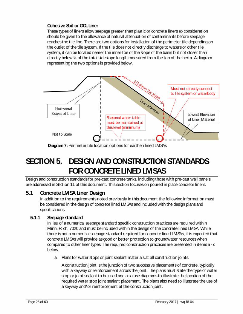
NOT TO SCALE
1 ft.
Seasonal water table must be maintained at this level (minimum)
Perimeter Tile Wall
Floor
Concrete, Plastic, or Composite Liner
Perimeter Tile
Seasonal water table must be maintained at this level (minimum)
Diagram 4: Envelope material for perimeter tile
Diagram 5: Perimeter tile location for vertical wall concrete tanks
Diagram 6: Perimeter tile location for sloping side wall concrete or plastic lined LMSAs
Page 26 of 60 February 2017 | wq-f8-04
Cohesive Soil or GCL Liner These types of liners allow seepage greater than plastic or concrete liners so consideration should be given to the allowance of natural attenuation of contaminants before seepage reaches the tile line. There are two options for installation of the perimeter tile depending on the outlet of the tile system. If the tile does not directly discharge to waters or other tile system, it can be located nearer the inner toe of the slope of the basin but not closer than directly below ⅔ of the total sideslope length measured from the top of the berm. A diagram representing the two options is provided below.
SECTION 5. DESIGN AND CONSTRUCTION STANDARDS FOR CONCRETE LINED LMSAS
Design and construction standards for pre-cast concrete tanks, including those with pre-cast wall panels, are addressed in Section 11 of this document. This section focuses on poured in place concrete liners.
5.1 Concrete LMSA Liner Design In addition to the requirements noted previously in this document the following information must be considered in the design of concrete lined LMSAs and included with the design plans and specifications.
5.1.1 Seepage standard In lieu of a numerical seepage standard specific construction practices are required within Minn. R. ch. 7020 and must be included within the design of the concrete lined LMSA. While there is not a numerical seepage standard required for concrete lined LMSAs, it is expected that concrete LMSAs will provide as good or better protection to groundwater resources when compared to other liner types. The required construction practices are presented in items a - c below.
a. Plans for water stops or joint sealant materials at all construction joints.
A construction joint is the junction of two successive placements of concrete, typically with a keyway or reinforcement across the joint. The plans must state the type of water stop or joint sealant to be used and also use diagrams to illustrate the location of the required water stop joint sealant placement. The plans also need to illustrate the use of a keyway and/or reinforcement at the construction joint.
Lowest Elevation of Liner Material
Horizontal Extent of Liner
Must not directly connect to tile system or waterbody
Not to Scale
Seasonal water table must be maintained at this level (minimum)
Diagram 7: Perimeter tile location options for earthen lined LMSAs
Page 27 of 60 February 2017 | wq-f8-04
b. Plans for sealing of all cracks which may extend through concrete liner with appropriate materials. (ex: epoxy injection; routing and joint sealant; stitching)
c. A LMSA floor of at least 5 in. thick and the floor has one of the following:
1) Steel reinforcing based on subgrade drag theory including provisions for supporting reinforcing steel in intended location by appropriate chairs or concrete blocks, or
2) Fiber reinforcing with specifications on type of fibers and the dosage rate.
5.1.2 Concrete Design Requirements The plans and specifications must include the following:
a. Requirements for the concrete mix including:
1) Compressive strength at stated age of concrete in walls, floors and footings;
2) Type and dosage rate of admixtures to be used (e.g., water reducers, plasticizers); and
3) Slump, temperature, and entrained air requirements.
b. Requirements for reinforcement including:
1) Type (grade) and size of reinforcing steel required for construction.
2) Location of rebar in walls (horizontal and vertical spacing and concrete cover), floors (spacing and cover) and footings (spacing and cover)
3) Measures will be taken to keep the rebar free of oil and debris prior to placing concrete;
4) Provisions for supporting reinforcing steel in intended location by appropriate chairs or concrete blocks.
c. Thickness of concrete in walls, floors (minimum of 5 in. thickness), and footings;
d. For concrete LMSAs with vertical walls and/or columns, indication on diagrams of the minimum requirements for footings.
Footings are required for walls and columns that support the top (floor) of the concrete LMSA (including slatted floors). The footings for walls and columns must be based upon the American Concrete Institute 318 standard. The minimum thickness of the bottom slab beneath the wall or column is 8 in. The bottom slab must also contain reinforcing steel and have provisions for supporting reinforcing steel in intended location by appropriate chairs or concrete blocks. At the right is a diagram of the minimum requirements for column footings.
e. For concrete LMSAs with slatted floors or solid tops, specifications that include the following:
1) Type of slatted floor system (concrete, plastic, etc.); and
2) Grouting requirements for concrete beams and slats to provide adequate support
NOT TO SCALE 5" floor 8”
Column
Diagram 8: Footings for columns within a concrete lined LMSA
Page 28 of 60 February 2017 | wq-f8-04
5.2 Concrete LMSA Construction Practices The ultimate quality of the concrete structure depends greatly on the site-specific conditions and the handling of construction materials, mainly concrete, during construction. Site conditions critical to successfully completing a high quality concrete structure relate mainly to the condition of the subgrade soils prior to placement of the footings and floor slab. Poor working conditions during the construction process such as available lighting, extreme hot or cold temperatures, extremely high winds or dry conditions and/or heavy rains can have significant effects on construction quality. Provisions for addressing these factors must be provided in the plans and specifications.
Improper handling of concrete during construction can severely degrade the quality of the structure and potentially result in costly short or long-term problems. One of the most common and severe problems is low-strength concrete (having a strength significantly less than specified) due to the addition of excess water to the mix prior to placement. Adding just 1 gallon of water to 1 cubic yard of concrete will increase the slump about 1 in. decrease the compressive strength about 200 to 300 pounds per square inch (psi), and increase the shrinkage potential by about 10% (Aberdeen Group, Item 2311).
Proper placing, consolidating, finishing and curing are essential to produce a storage structure which meets the approved plans and specifications.
5.2.1 Quality Assurance/Quality Control Plan
The plans and specifications for the LMSA must include information on the testing that will be performed during construction to evaluate conformance to the approved design plans and specifications which is referred to as a quality assurance/quality control (QA/QC) plan. The MPCA recommends and encourages QA/QC that goes beyond the minimum requirements for all concrete LMSA projects. Additional requirements may be necessary in areas more sensitive to groundwater contamination, such as those within Karst topography. The QA/QC plan should address the following:
a. Identification of the person responsible for conducting the required QA/QC inspections/tests. This person must be one of the following:
1) ACI concrete 1 field test certified,
2) A P.E. (licensed in MN) or person working under their direct supervision, or
3) A NRCS approved person
b. Inclusion of specifications for ASTM testing methods during construction. The testing methods must include either of the following:
1) ACI 318-02 field testing methodology
2) ACI 301-99 field testing methodology
3) Follow all field testing methodology of ASTM C-94 “Specification for Ready-Mixed Concrete.”, or
Page 29 of 60 February 2017 | wq-f8-04
4) List of all tests to be performed which includes all of the following:
a) Concrete sampling according to ASTM C-172 “Method of Sampling Freshly Mixed Concrete”
b) Compressive strength according to ASTM C-31 & C-39 “Test for Compressive Strength of Cylindrical Concrete Specimens.” One test set will consist of the average test strength of two (2) sample cylinders.
c) Temperature according to ASTM C-1064 Standard Test Method for Temperature of Freshly Mixed Portland Cement Concrete.”
d) Slump according to ASTM C-143 “Test for Slump of Hydraulic Cement Concrete”. If plasticizer is used in concrete mix indicate dosage
e) If air-entrained concrete is specified, then information concerning the indicated type and dosage rate of air-entraining admixture or air-entraining cement must be indicated on the batch tickets. The MPCA recommends but does not require air content testing according to ASTM C-138 or C-173 or C-231.
c. Identification of the sampling frequency which must occur whenever a new mix or concrete supplier is used and at a minimum of every 150 cubic yards for strength.
d. Provisions for concrete placement during hot and cold weather.
e. Hot weather concrete placement should follow ACI 305R “Hot Weather Concreting” (or equivalent). Hot weather conditions include periods of any combination of hot temperatures (greater than 90° F), extremely dry, and extremely windy conditions.
f. Cold weather concrete placement should follow ACI 306.1 “Standard Specification for Cold Weather Concreting” (or equivalent). Cold weather is defined in ACI 306R as a period when, for more than three consecutive days, the following conditions exist:
1) The average daily temperature is less than 40° F (5 C); and
2) The air temperature is not greater than 50° F (10 C) for more than one-half of any 24 hour period.
g. Methods for liner protection during and after construction. Provisions for protection from liner drying and cracking must be included and could incorporate spraying with water, covering with burlap, applying steam, or applying a curing compound.
h. Provisions for management during periods on non-use in freeze and thaw cycles must be included and could incorporate either heating the structure or keeping a small amount of liquid in the LMSA.
5.2.2 Concrete Truck Washout Areas Washout of concrete trucks can become an issue at construction sites. Washout should not occur on a roadway or near a road ditch even though these areas are convenient. In general washout out from concrete trucks must be deposited in a container or lined pit. Once the washout has dried/hardened, up to 0.5 cubic yards can be buried on site. More information is available in this fact sheet: http://www.pca.state.mn.us/index.php/view-document.html?gid=7397.
SECTION 6. DESIGN AND CONSTRUCTION STANDARDS FOR EARTHEN LINED LMSAS
6.1 Earthen LMSA Liner Design In addition to the requirements noted previously in this document the following information must be considered in the design of earthen lined LMSAs and included with the design plans and specifications.
6.1.1 Seepage standard Minn. R 7020 requires that non-concrete liners for LMSAs be designed to achieve a theoretical seepage rate of no more than 1/56 of an inch per day. What the rule is referring to is unit seepage which is also known as specific discharge. Unit seepage, or more commonly referred to as seepage in the rule, is a measure of the seepage of the pollutant through a cross sectional area. Although it appears that the units associated with the seepage standard in the rule are simply Length (L)/Time (T) the units are actually L3/L2/T as unit seepage is a measure of the flow rate through a cross sectional area of soil. Therefore, although the seepage standard is identified in the units of in/day, the actual units of the seepage standard referenced in the rule are 1/56 in3/in2/day.
More commonly the seepage standard in the rule is expressed in the units of gal/acre/day. Converting the 1/56 in/day, which is actually 1/56 in3/in2/day, can be done as follows:
The required seepage standard is routinely considered to be approximately 500 gal/acre/day; however, this is slightly more than the actual 485 gal/acre/day allowed by the rule. Long-term protective and maintenance measures are required to meet this limit throughout the life of the structure.
Commonly a permeability test is done is done to verify that the constructed liner within a basin complies with the seepage standard. Typically the test results are reported in units of cm/sec (L/T). However, the test used to compute this value measures the flow through a given cross section of soil, or more simply flow through a cross sectional area of soil. As discussed above, the units of the measured value (permeability) are actually cm3/cm2/sec and are commonly reduced to cm/sec. On occasion the result of the permeability test is incorrectly compared directly to the seepage standard identified in the rule as the shortened units are the same (L/T). As identified above, the rule refers to unit seepage which is not equivalent to a permeability test result. Seepage is greatly affected by the height of the column of water above the soil liner as well as the thickness of the soil liner. Therefore, Darcy’s Law must be used to calculate the seepage rate of the liner material.
Determination of a theoretical seepage rate through a liner is based on the thickness and permeability of the liner material and the depth of the liquid stored, using Darcy’s Law. The seepage of a basin should be calculated when the basin is at is maximum design operating capacity. An example of this calculation is provided below:
dayacregal
acreft
ftgal
ftin
inft
dayinin
-=´´´´
-485
143560
148.7
1144
17281
561 2
32
2
3
3
2
3
Page 31 of 60 February 2017 | wq-f8-04
Calculation for Flow Rate Through Soil Liner Alone (Darcy’s Law): Example: A 10 ft. deep basin with 2 ft. of freeboard and a 2 ft. thick clay liner with an assumed permeability of 1 x 10⁻⁷ cm/sec and basin bottom area of 60,000 ft2
Q = KiA where: Q = flow rate (ft3/day) K = hydraulic conductivity of liner material (ft./day) i = hydraulic gradient = (h + D)/D (unitless) A = area (ft2) h = “head” or depth of liquid (ft.) D = thickness of liner (ft.)
In this example:
h = 8 ft. (total depth less freeboard) D = 2 ft. i = (8 ft+2 ft.)/2 ft. = 5 A = 60,000 ft2
Note: This example only calculates seepage from the basin bottom and does not include seepage from the sidewalls which is typically less than the seepage from the basin bottom but should still be considered in the design.
The thickness of the liner is determined by the design engineer via Darcy’s Law but must be a minimum of 2 ft. If the liner is installed on a loose sand or gravel sub-base then the liner must be at least 0.5 ft. thicker than the minimum design thickness to ensure proper compaction.
The basin must not exceed the seepage standard at any depth or location within the LMSA. For example, the amount of sidewall seepage is typically less than the amount of LMSA floor seepage. Averaging these two values can lead to a situation when the average seepage (floor-sidewall combination) is below the allowable threshold but the LMSA floor seepage itself is above the threshold. In this situation the LMSA would be considered non-compliant as a portion of the LMSA liner (floor) does not meet the required seepage standard.
The required seepage rate has to be maintained over the entire design life of the basin. Designers must consider not only such issues as erosion and mechanical damage, but others such as potential loss of fine particles from liner soils into coarser underlying deposits due to soil piping. Freeze-thaw actions and desiccation increase the hydraulic conductivity of soil liners. However, clogging of soil pores by manure particles and creation of a biological mat or seal decreases permeability and can offset some of these factors. A quality design addresses these issues.
dayftxdaycm
ftcmxK /108.21
sec8640048.301
sec101 4
7-
-
=´´=
daygal
ftgal
dayftft
dayftxQ 3.628
148.784600005108.2
3
32
4
=´=´´=-
dayacregal
acreft
dayftgal
ftdaygalSeepage
-=´
-==
15.4561
435600105.060000
/3.628 2
22
Page 32 of 60 February 2017 | wq-f8-04
6.1.2 Location of Cohesive Soil Material Typically an earthen liner is proposed when a suitable cohesive soil underlies the site upon which the LMSA is proposed to be located. On occasion earthen lined LMSAs are proposed when a cohesive soil must be brought to the site in order to construct the LMSA. The site upon which the cohesive soil is removed from is called the “borrow” site. When a borrow site is required to provide cohesive soils for construction of an earthen lined LMSA the following information must be included with the design plans and specifications for the project.
a. Location of the borrow site.
b. Soils investigation performed at the borrow site to adequately quantify the quality and extent of the soil. The minimum number of borings shall be equivalent to the number of borings required for the construction of the proposed LMSA as outlined in part 3.2.2 above.
c. Estimation of volume of adequate soil available at the borrow site.
6.1.3 Evaluation of the Proposed Earthen Liner Soil The cohesive soil to be utilized for the liner of a LMSA whether on site or from a borrow site must undergo a battery of tests during the design phase of the LMSA to provide adequate assurance that the material can achieve compliance with the seepage standard. Typically the soil samples needed for testing are collected during the soils investigation process. The required tests as well as the frequency and acceptable test results are presented below.
a. Atterberg limits, Plasticity Index (P.I.);
b. Sieve analysis results including the percent passing the #200 sieve and percent retained on the #4 sieve;
c. Optimum liner soil moisture content and maximum density for compaction;
d. Permeability test(s) if the design specifications require a soil with less than 1 x 10⁻⁷ cm/sec permeability in order to achieve the seepage standard of 1/56 inch/day as determined using Darcy’s Law.
Table 3: Minimum testing requirements PRIOR to construction
A flow chart of Pre and Post Construction testing requirements is presented in APPENDIX A
Test Performed Frequency (minimum) and Method Acceptable Range
Particle Size (Sieve Analysis)
1/soil type to be used ASTM D422
Greater than 20% passing #200 Less than 20% retained on #4
Atterberg Limits (Plasticity Index)
1/soil type to be used ASTM D4318
P.I. of 11 to 30
Standard Proctor (Optimum Moisture and Density)
1/soil type to be used ASTM D698
Permeability (required when PI not 11 – 30 or less than 1 x 10⁻⁷ cm/sec needed to meet the seepage standard)
1/soil type per every 4 acres of basin area, round up to nearest integer (minimum of 2) ASTM D5856 or D5084
Maximum allowable seepage of 1/56 of an inch per day as determined using Darcy’s Law.
Page 33 of 60 February 2017 | wq-f8-04
6.1.4 Utilizing Existing “In-Place” Soils for Earthen Liner The term “in-place” refers to practice of using native soils with minimal disturbance to create the earthen liner of the LMSA. In other words, the construction practice consists of excavation of the proposed LMSA without the required removal and recompaction of the native cohesive soil material. In most instances the use of “in-place” soils is not considered to provide an adequate seepage control as there is no assurance that soils of low permeability are of sufficient thickness in all areas of the structure and sand/gravel lenses, and ”macropores” from soil fissures, root channels, and animal and earthworm burrows are present in most undisturbed fine textured soils, which provide conduits for leakage from the structure.
However, in some instances the MPCA may approve use “in-place” soils for an earthen lined LMSA. With prior approval from the MPCA, “in-place” soils may be utilized as liners in situations where a surface water pollution abatement system has been proposed and the following conditions are met:
a. There is an existing feedlot facility of less than 300 AU with a documented pollution hazard that requires construction of a LMSA to correct;
b. Construction is not within delineated wellhead protection areas of public water supply wells;
c. All wells are located at least 150 ft. (300 ft. for sensitive wells) from the proposed LMSA;
d. The facility is not in a geologically sensitive area (e.g. sinkhole plain);
e. For facilities in a Karst susceptible area the separation to bedrock is verified as 20 ft.
f. Native soil physical properties (verified by lab tests) meet the acceptable ranges for Sieve Analysis and Atterberg Limits identified in Table 3;
g. No sand/gravel lenses or soils classified by the NRCS 313 standard as group I or II are encountered during the soils investigation;
h. Basin storage capacity is less than 750,000 gallons;
i. Basin depth does not exceed 9 ft.;
j. Sideslopes will not be steeper than 3:1 (horizontal: vertical);
k. The upper 6 in. (minimum) of the excavated pond surface (including sidewalls) is scarified and re-compacted/remolded;
l. Protection of the basin sideslopes and floor from damage caused by erosion, manure agitation, and pumping is provided as described in item 6.1.5 below;
m. Plans and specifications are prepared by a registered professional engineer or under the NRCS approval authority;
n. Daily (at a minimum) construction inspection is done; and
o. A compacted cohesive soil liner (removal and recompaction of liner material) is planned if sand or gravel lenses, bedrock, or soils classified by the NRCS 313 standard as group I or II are discovered during construction.
Page 34 of 60 February 2017 | wq-f8-04
6.1.5 Erosion/Scour Protection The cohesive soil liner must be protected in order to maintain a seepage rate which is less than 1/56 inch per day. In order to maintain a liner it is crucial to incorporate measures to protect the liner from erosion, secondary desiccation, and freeze-thaw action. The following items should be included in the design and construction to provide long-term protection of the liner:
There must be provisions for protecting the in-place liner from development of erosion rills over the design life. These measures could include seeding the upper portions of the berm with short rooted vegetation and/or placing a protective layer of material over the exposed sidewalls (e.g. rip-rap, sacrificial soil layer, etc.). It is not unusual for erosion rills several inches deep to form on basin sidewalls. This should be taken into account in design of the liner.
Concrete Agitation/Pumping Pads. Pumping and agitation equipment can damage unprotected liners both from wheel damage as the equipment moves across unprotected liner and from agitation and pumping activities. Therefore, provisions for protection of applied or constructed liners from agitation or pumping equipment must be included in the plans. A commonly used method is the construction of concrete ramps and pads in the basin floor at all locations where agitation and pumping may occur.
Concrete pump-out ramps (the portion on the basin sidewall) must be a minimum of 16 ft. wide or alternatively have a 6 in. curb installed to prevent equipment from accidentally leaving the ramp. The ramps must extend from the agitation pad to the top of the LMSA sidewall. The agitation pads (the portion placed on the floor of the basin) must be at least 20 ft. by 20 ft. in surface area and be designed as a sump, have a 6 in. curb installed at the rear of the pad, or be at least 20 ft. by 30 ft. The sump or curb design feature will direct some of the agitation energy upwards and thereby minimize scour at the concrete - earthen liner interface and provide a way for manure pumper to “locate” the extent of the pad and center the agitation equipment over it. The enlarged pad will provide for more area for protection of the liner during agitation. An example of a sump is shown in Diagram 9.
It is also best to install posts along the top of the basin berm to make it easier to locate the ramps and pads for the agitation equipment. Consultation with a professional manure pumping contractor can help identify locations for ramps and pads, but they should generally be located at approximately 100 ft. intervals.
Concrete Ramp
Agitation Pad (sump design) Splash Pad
Concrete Collar (with waterstop)
Cohesive Soil Liner NOT TO SCALE
Diagram 9: Concrete pads for liner protection
Page 35 of 60 February 2017 | wq-f8-04
Pipe Inlets/Outlets. Flow from pipe inlets into the basin can cause significant erosion of the soil liner if the liner is not protected (e.g. with concrete splash pads). A detailed drawing of the pipe inlets and outlets as well as an explanation of how they are to be installed should be included in the plans and specifications. An example of a pipe inlet/outlet detail is shown in Diagram 9.
In addition, investigations have shown that basins which are found to exceed the seepage standard typically have problems with leakage around inlet and outlet pipes. Significant attention to installation details is required in design and construction to prevent leakage. Installation of a bentonite collar, concrete collar with water stop around the pipe within the concrete or other leakage prevention is required.
6.2 Earthen Lined LMSA Construction Practices 6.2.1 Interior Sideslope Construction
Interior sideslopes can be constructed in horizontal (“stair step”) or parallel (“bathtub”) lifts.
Horizontal Lifts (“stair step” method) The sideslope angle must not exceed 2:1 (horizontal: vertical) when horizontal lifts are used.
When constructing with horizontal lifts it is important to observe each lift to make sure there are no zones of permeable soil (see Diagram 9) which will provide a direct flowpath through the liner, and that lift interfaces are eliminated by scarification and remolding of soil clods.
The specifications shall identify a minimum horizontal lift thickness and width to ensure the minimum thickness (measured perpendicular to the sidewall) of liner is achieved. The width of a lift can be calculated for a given lift thickness using the following equation:
S = Slope of Interior Sidewall (e.g. 3, indicating 3:1) T = Lift Thickness Prior to Compaction (ft.) W = Lift Horizontal Width (ft.) D = Liner Thickness (ft.)
Example: S = 3:1 T = 6 in = 0.5 ft. D = 2 ft.
Parallel Lifts (“bathtub” method). The sideslopes can be no steeper than 3:1 (horizontal: vertical) when parallel lifts are used. In addition, it is important to monitor construction to make sure there is enough compactive energy to break up clods during compaction of the side walls and to eliminate lift interfaces. The designer should carefully consider specifications for equipment and direction of travel of compaction equipment.
Horizontal Lifts
2 1
Parallel Lifts
3 1
÷÷ø
öççè
æ+
+´´= T
SSDSW
21
lift widthfoot 8an least at use 8.75.03
31232
Þ=÷÷ø
öççè
æ+
+´´=W
Diagram 10: Options for construction of sideslopes of an earthen LMSA liner
Page 36 of 60 February 2017 | wq-f8-04
6.2.2 Exterior Sideslope Construction All exterior sideslopes should be 3:1 (horizontal: vertical) or flatter and are to be covered with 4 to 6 in. of topsoil and planted with a vegetative cover to prevent erosion. Deep rooted plants such as alfalfa, cattails, shrubs and trees shall not be allowed to grow on the banks since the roots may penetrate and damage the liner material.
6.2.3 Placement of Liner Material Except in the case when an in-place soil liner is authorized by the MPCA the following criteria apply to the placement of the liner material:
a. Moisture content must be maintained at 0 to 3% above optimum for compaction, as determined by preconstruction testing of the liner material. Therefore, equipment for drying or wetting liner soils as needed should be available on site at all times and required in the specifications.
b. Rocks larger than 4 in. are not allowed in the liner material and must be removed during liner placement.
c. Placement of soil must be in layers no thicker than 3 in. greater than the tamping roller feet and not be more than 9 in. thick (before compaction).
d. Each layer must be compacted by sufficient passes (minimum of three) of compaction equipment to remold soil clods, and eliminate macropores and lift interfaces. This may take five or more passes of the compaction equipment, depending on conditions. To eliminate lift interfaces, it is important to scarify the surface of previously compacted lifts prior to placement of the next lift and to have deep-footed rollers which penetrate into this previous lift.
e. When substandard materials are encountered, such as a sand vein in a predominately clay till soil, provisions must be made to over-excavate the substandard by a minimum of 2 ft. and recompact the excavated area with the cohesive soil used for the liner to avoid creating a preferential flow path for seepage from the LMSA.
6.2.4 Construction of earthen liners between October 15 and April 15.
For any compacted cohesive soil liner construction between October 15 and April 15 a report prepared by the design engineer must be submitted and approved by agency staff before construction can begin and/or continue. The report must contain the following information:
a. The estimated time period necessary to complete basin cell liner construction.
b. Definition of specific conditions which would prohibit further construction due to weather conditions or would prohibit addition of manure to the basin.
c. The estimated time period necessary to pre-charge the completed basin with water as recommended by the design engineer to protect the liner from drying or freezing, if the basin cannot be completed prior to winter.
d. A definition of frozen soils, for use by the design engineer, inspector, and contractor.
e. The precautions to be taken to protect basin cell liner from drying and freezing while construction is completed and pre-charge (if necessary) is conducted.
Upon review of the information the MPCA will provide written approval to begin/continue the construction of the earthen lined LMSA between October 15 and April 15.
Page 37 of 60 February 2017 | wq-f8-04
6.2.5 Quality Assurance/Quality Control Plan The plans and specifications for the LMSA must include information on the testing that will be performed during construction to evaluate conformance to the approved design plans and specifications which is referred to as a quality assurance/quality control (QA/QC) plan. The MPCA recommends and encourages QA/QC that goes beyond the minimum requirements for all LMSA projects. Additional requirements may be necessary in areas more sensitive to groundwater contamination, such as those within Karst topography.
The QA/QC plan should address the following:
a. Identification of the person responsible for conduction the required QA/QC inspections/tests. This person must be one of the following:
b. A P.E. (licensed in MN) or person working under their direct supervision, or
c. A NRCS approved person
d. Inclusion of specifications for ASTM testing methods and frequencies during construction. The minimum testing requirements to be followed during and/or after construction are identified in Table 4 below and summarized in APPENDIX A of this document.
Table 4. Minimum testing requirements DURING and AFTER construction:
a Tests should occur at least after each foot of liner material is placed (ideally after each lift). b The MPCA reserves the right to require post-construction permeability testing at their discretion in
sensitive areas or when construction methods are in question.
Note: A method specification provides specific items that will be monitored/examined during liner placement that provides reasonable assurance that the liner installation will be completed satisfactorily. (e.g. A defined number of passes with a sheepsfoot)
Test Frequency and Method Acceptable Range Water Content of Soils a
(During Construction) 4/acre/ft. of liner thickness (min of 5/ft. of liner thickness) ASTM D6938, D2216, D4643, D4959, or D4944
Maintain at 1% below to 3% above optimum moisture for compaction
Note: An MPCA approved method specification can be substituted for this test (for any size facility)
Density/Compaction a
(During Construction) 4/acre/ft. of liner thickness (min of 5/ft. of liner thickness) ASTM D6938, D2167, D5080, D2937, or D1556
Minimum of 95% of standard proctor. (Modified proctor may be used as appropriate).
Note: With MPCA pre-approval a method specification may be substituted for this test provided post-construction permeability testing is not required and the facility has 300 or less AU’s.
Permeability b
(required when less than 1 x 10⁻⁷ cm/sec needed to meet the seepage standard)
1 per 2 acres of basin area with a minimum of one in the sidewall and one in the floor per cell ASTM D5084 or D5856
Maximum allowable seepage of 1/56 of an inch per day as determined using Darcy’s Law.
Page 38 of 60 February 2017 | wq-f8-04
SECTION 7. DESIGN AND CONSTRUCTION STANDARDS FOR GEOSYNTHETIC CLAY LINERS (GCL)
7.1 GCL LMSA Design The most commonly utilized GCL material consists of a thin layer of bentonite (less than 1 in.) sandwiched between two woven geotextile fabrics that are needle punched together and will be the focus of this document. The other type of GCLs, which are less commonly used in Minnesota, will not be discussed in this document. If a designer wishes to utilize a different GCL please consult with the MPCA early in the design phase so that its proposed use can be evaluated.
In addition to the requirements noted previously in this document the following information must be considered in the design of GCL lined LMSAs and included with the design plans and specifications.
7.1.1 Seepage Standard Minn. R 7020 requires that non-concrete liners for LMSAs be designed to achieve a theoretical seepage rate of no more than 1/56 of an inch per day. The required seepage standard is routinely considered to be approximately 500 gal/acre/day; however, this is slightly more than the actual 485 gal/acre/day allowed by the rule. Long-term protective and maintenance measures are required to meet the seepage rate limit throughout the life of the structure.
Commonly a permeability test is done to verify that the liner material complies with the seepage standard. With a GCL liner the manufacturer has performed the permeability analysis and should provide the results of the analysis with the product. On occasion the result of a permeability test is incorrectly compared directly to the seepage standard identified in the rule. As identified above, Minn. R. ch. 7020 contains a seepage standard which is not equivalent to a permeability test result, as seepage is greatly affected by the height of the column of water above the liner as well as the thickness of the liner. Therefore, Darcy’s Law must be used to calculate the seepage rate of the liner material. The seepage of a basin should be calculated when the basin is at is maximum design operating capacity.
A more comprehensive discussion of the seepage standard in Minn. R. ch. 7020 as well as an example calculation using Darcy’s Law is provided within the earthen liner design section of this document.
7.1.2 Material Requirements The design plans must indicate what type of GCL is proposed for use as a liner for the LSMA. There are no current restrictions on the brand/type of GCL to be utilized provided the material can achieve the required seepage standard. The GCL material must meet the requirements of NRCS material specification 595 (geosynthetic clay liners). The NRCS 595 material specification standard can be found here: ftp://ftp-fc.sc.egov.usda.gov/NHQ/eng/neh642/ms-pdf/ms595.pdf and as APPENDIX E to this document.
In some situations, such as installation of a GCL liner in an area with extensive sand or gravel deposits, a GCL that incorporates a petroleum based synthetic liner or a cohesive soil sub-liner may be required to provide additional protection to the groundwater of the area.
7.1.3 Protection of Liner from Damage The design plans must include measures to be used to protect the GCL liner from damage. These include the installation of a cover material, pump-out ramps, agitation pads, and pipe inlet/outlet protection.
Cover Material All GCLs currently utilized as a LMSA liner required the installation of a cover soil after GCL installation. The plans and specifications for the project must include the minimum depth of soil cover to be utilized. Cover soil thickness should conform to the manufacturer’s recommendations but shall be at least 12 in. and should be increased to at least 18 in. on the sideslopes in order to address concerns of material slump or erosion from wave action or precipitation.
Additionally, the plans must include restrictions on the type of material to be used so that materials with large and/or angular rocks are not used for the cover material. Cover soils shall not contain sharp, angular stones or any objects that could damage the liner. Maximum allowable particle size of soil cover material shall be ½ - in., unless the liner is protected by a 10-oz/sq. yd. or heavier non-woven geotextile cushion material.
Cover soil shall be placed within 24 hours after placement of the liner to minimize the potential for damage from various sources, including precipitation, wind, and ultra-violet exposure.
Concrete Agitation/Pumping Pads.
Pumping and agitation equipment can damage liners both from wheel damage as the equipment moves across unprotected liner and from agitation and pumping activities. A commonly used method for protection is the construction of concrete ramps and pads in the LMSA floor at all locations where agitation and pumping may occur.
Concrete pump-out ramps (the portion on the basin sidewall) must be a minimum of 16 ft. wide or alternatively have a 6 in. curb installed to prevent equipment from accidentally leaving the ramp. The ramps must extend from the agitation pad to the top of the LMSA sidewall. The agitation pads (the portion placed on the floor of the basin) must be at least 20 ft. by 20 ft. in surface area and be designed as a sump, have a 6 in. curb installed at the rear of the pad, or be at least 20 ft. by 30 ft. The sump or curb design feature will direct some of the agitation energy upwards and thereby minimize scour at the concrete – GCL cover material interface and provide a way for manure pumper to “locate” the extent of the pad and center the agitation equipment over it. The enlarged pad will provide for more area for protection of the liner during agitation. An example is shown in Diagram 11 below.
It is also best to install posts along the top of the basin berm to make it easier to locate the ramps and pads for the agitation equipment. Consultation with a professional manure pumping contractor can help identify locations for ramps and pads, but they should generally be located at approximately 100 ft. intervals.
Page 40 of 60 February 2017 | wq-f8-04
Pipe Inlets/Outlets. Flow from pipe inlets into the basin can cause significant erosion of the cover material if protection is not provided (e.g. with concrete splash pads). A detailed drawing of the pipe inlets and outlets as well as an explanation of how they are to be installed should be included in the plans and specifications. An example of a pipe inlet/outlet detail is shown in Diagram 11.
In addition, investigations have shown that basins which are found to exceed the seepage standard typically have problems with leakage around inlet and outlet pipes. Significant attention to installation details is required in design and construction to prevent leakage. Installation of a bentonite collar around the pipe or other leakage prevention is required.
7.2 GCL Synthetic Liner Construction Practices It is recommended that a reputable company will extensive experience in installation of GCL liners be selected for placement of the liner. At a minimum installation should occur in accordance with the NRCS construction specification 98 – Geosynthetic Clay Liner available at ftp://ftp-fc.sc.egov.usda.gov/NHQ/eng/neh642/cs-pdf/cs098.pdf and included as APPENDIX H to this document.
7.2.1 Delivery of Materials The GCL liner material must be stored in a dry area as it cannot be used for a basin liner once the roll of liner material becomes wet. Typically GCL is delivery with a plastic sleeve to protect it from moisture but additional protection may be necessary. GCL material must be unloaded from the truck using a core pipe and spreader bar, slings, or stinger bar as the roll of material must be properly supported when unloaded.
7.2.2 Earthwork Requirements The manufacturer’s recommendations should be followed for subgrade preparation. At a minimum the following items should be addressed. The subgrade surface should be dry, firm, and free of voids, cracks, ice, or standing water. The soils used for the subgrade must be free of rocks larger than ⅜ in., all angular rocks, sticks or other material that could potentially puncture the liner. The subgrade must be prepared with a smooth drum roller to eliminate any wheel ruts, footprints, or protrusions from the subgrade.
Concrete Ramp
Agitation Pad (sump design)
Splash Pad
GCL Liner NOT TO SCALE GCL Liner Cover Material
GCL Cover Material Extra Sheet
of GCL Liner
Granular Bentonite
Diagram 11: Pipe installation methods and liner protection measures for a GCL lined LMSA
7.2.3 Installation of Liner Material The installation of a GCL liner should follow the manufacturer’s recommendations. In general the following items must be considered. The GCL liner material requires the construction of an anchor trench at the top of the berm of the LMSA. The anchor trench should have a rounded edge to minimize stress on the GCL liner material. The GCL should cover the entire trench floor but not extend up the rear trench wall.
The GCL material must be installed with the use of a spreader bar. The GCL roll should never be allowed to freely roll down the sloped sides of the LMSA berm. No equipment should drive on the GCL material except an ATV that does not make any sudden turns, starts, or stops. The GCL must be overlapped a minimum of 12 in. at the roll edge seams and at least 2 ft. at a “butt” seam. A continuous bead of granular sodium bentonite must be used between the overlapped panels. End of roll seams on slopes should be avoided.
Only has much GCL should be installed as can be covered in one day. GCL should not be left uncovered overnight. If the GCL material is hydrated prior to the installation of the cover material removal reinstallation of material will likely be required. Cover material shall be placed without equipment driving on the liner material or driving where less than 12 in. of cover material has been laid. Soil cover should be pushed up on slopes, not down slopes, to minimize tensile forces on the GCL material.
7.2.4 Quality Control/Quality Assurance Plan The quality control/quality assurance plan for a GCL liner is very limited. Unlike earthen or concrete liners that are constructed on-site this product is manufactured off-site in a controlled environment and is simply “placed” during construction. Therefore, a QA/QC plan for a GCL liner should simply identify the inspection plan that the engineer will observe including observations of the liner subgrade prior to placement, deployment of the liner, seaming operations, anchoring activities, and installation of cover material.
Diagram 12: GCL installation with spreader bar and anchor trench detail
Diagram from Cetco Lining Technologies
Photo from West Central Technical Service Area
Page 42 of 60 February 2017 | wq-f8-04
SECTION 8. DESIGN AND CONSTRUCTION STANDARDS FOR PETROLEUM BASED LINERS
8.1 Petroleum Based Synthetic Liner Design There are a variety of petroleum based synthetic liners that may be suitable for installation in a LMSA such as; high density polyethylene (HDPE), linear low density polyethylene (LLDPE), and Ethylene Propylene Diene Monomer (EPDM). This document will focus on the two primary types installed in Minnesota, HDPE and EPDM; however LLDPE practices are very similar to HDPE. Except where noted, the term “plastic” will refer to HDPE and EPDM liners collectively even though EPDM is a rubberized product.
8.1.1 Seepage Standard Minn. R 7020 requires that non-concrete liners for LMSAs be designed to achieve a theoretical seepage rate of no more than 1/56 of an inch per day. The required seepage standard is routinely considered to be approximately 500 gal/acre/day; however, this is slightly more than the actual 485 gal/acre/day allowed by the rule. Long-term protective and maintenance measures are required to meet this limit throughout the life of the structure.
However, the seepage standard in Minn. R. ch. 7020 is difficult to apply to plastic liners as seepage from a plastic lined LMSA does not occur via liquid passing through the plastic. Seepage from a plastic lined basin occurs at areas where the material has been damaged such as a faulty joint or a puncture of the plastic liner material. Therefore, rather than performing a numerical analysis of the seepage from a plastic lined LMSA, requirements are placed on the type of material, installation procedures, and post-construction testing to provide assurance that the plastic lined LMSA is capable of achieving compliance with the seepage standard.
8.1.2 Material Requirements The design plans must indicate what type of plastic is proposed for use as a liner for the LSMA. Depending on the type of material to be utilized different material requirements apply. A plastic liner material must have a minimum thickness of 60mil (45 mil for EPDM) and shall meet the minimum requirements of NRCS material specification 594 (flexible membrane liners). The NRCS 594 material specification standard can be found here: ftp://ftp-fc.sc.egov.usda.gov/NHQ/eng/neh642/ms-pdf/ms594.pdf and as APPENDIX F to this document.
8.1.3 Venting of Plastic Lined LMSAs Natural gas production within the soil profile beneath a plastic lined LMSA is a very real concern. Gas production beneath plastic lined LMSAs most commonly occurs as a result of natural degradation of organic materials within the soil profile beneath the LMSA. Organic materials may have been deposited naturally, such as a wetland area, or may have been the result of long term seepage of manure or manure contaminated runoff into the soil profile. Areas of highly organic soils should be avoided for construction of a plastic lined LMSA. A gas venting system is necessary to prevent the accumulation of gases beneath the plastic liner. Without a way to remove the accumulated gases, bubbles or “whales” can develop within the LMSA. These whales significantly reduce the storage capacity of the LMSA and place unanticipated stresses on the material and the seams of the plastic lined LMSA. Once a whale begins to develop it typically grows substantially in size in following years and can lead to bubbles whose height exceeds the top of the LMSA berms. (see Figure 8)
ALL plastic lined LMSAs must have provisions for the installation of a venting system. The design of the venting system shall include Identification of the type of venting system to be used as well as specified location and spacing of the venting system. It is strongly recommended that provisions to allow accumulated moisture to be removed from venting system so that it does not prevent the venting of accumulated gases be utilized, especially when the seasonal water table is found to be above the bottom of the LMSA. Additionally, consideration should also be given to creating a slight slope on the LMSA floor to encourage gas migration to the inside toe of the LMSA sidewall where it is easier for the gases to access the vent located at the top of the LMSA sidewall. The slight slope will also allow for more efficient collection of accumulated moisture within the venting system.
8.1.4 Protection of Liner from Damage
As discussed above, organic material must be precluded from being placed beneath the plastic LMSA liner. The vast majority of the whales result from damage to the plastic liner during agitation or failure of a seal at a pipe penetration point; which places manure, with its abundance of organics, beneath the plastic liner. Therefore, extra precautions are necessary to safeguard the plastic liner from damage and potential development of whales. These include the installation of pump-out ramps, agitation pads, and pipe inlet/outlet protection.
Pipe Inlets/Outlets.
A detailed drawing of the pipe inlets and outlets as well as an explanation of how they are to be installed should be included in the plans and specifications. In addition, investigations have shown that basins which are found to exceed the seepage standard typically have problems with leakage around inlet and outlet pipes. Significant attention to installation details is required in design and construction to prevent leakage. An example of a pipe inlet/outlet detail is shown below.
Diagram 13: Pipe penetration detail for a plastic lined LMSA (NRCS AWFH-Appendix 10E)
Page 44 of 60 February 2017 | wq-f8-04
Concrete Agitation/Pumping Pads. Pumping and agitation equipment can damage liners both from wheel damage as the equipment moves across unprotected liner and from agitation and pumping activities. Concrete ramps and pads must be installed in the LMSA floor at all locations where agitation and pumping may occur.
Concrete pump-out ramps (the portion on the basin sidewall) must have a 6 in. curb installed to prevent equipment from accidentally leaving the ramp and is recommended being at least 16 ft. wide. The ramps must extend from the agitation pad to the top of the LMSA sidewall. The agitation pads (the portion placed on the floor of the basin) must be at least 20 ft. by 20 ft.in surface area. The agitation pads must be designed as a sump, have a 6 in. curb installed at the rear of the pad, or be at least 20 ft. by 30 ft. The sump or curb design feature will direct some of the agitation energy upwards and thereby minimize scour at the concrete – plastic liner interface and provide protection from over-backing into the LMSA with agitation equipment. Additionally, these design features provide a way for manure pumper to “locate” the extent of the pad and center the agitation equipment over it. The enlarged pad will provide for more area for protection of the liner during agitation.
There are two methods to install concrete pump-out ramps and agitation pads within plastic lined LMSAs. The first method is to simply pour the concrete on top of the plastic liner, creating a “raised” pump-out ramp and agitation pad. The second method is to recess the concrete into the subgrade of the LMSA so that the concrete will be flush with the plastic liner. Then either an embedment strip can be poured within the concrete to which the plastic liner can then be welded or a mechanical fastener can be installed to secure the plastic liner to the concrete. The preferred method is to pour the pump-out ramps on top of the plastic liner as it minimizes the chances for failure near an agitation point. The design must identify which method will be used for pump-out ramps and pads.
It is also best to install posts along the top of the basin berm to make it easier to locate the ramps and pads for agitation. Consultation with a professional manure pumping contractor can help identify locations for ramps and pads, but they should generally be located at approximately 100 ft. intervals.
8.2 Petroleum Based Synthetic Liner Construction Practices Installation of plastic liners requires specially trained crews and equipment; therefore this topic will not be covered in detail in this document. It is recommended that a reputable company will extensive experience in installation of plastic liner be selected for placement of the liner. At a minimum installation should occur in accordance with NRCS construction specification 97 – Flexible membrane liner available at ftp://ftp-fc.sc.egov.usda.gov/NHQ/eng/neh642/cs-pdf/cs097.pdf and included as APPENDIX G to this document.
Figure 7: Concrete ramp on top of HDPE (note geo-textile between concrete and HDPE)
8.2.1 Earthwork Requirements The manufacturer’s recommendations should be followed for subgrade preparation. At a minimum the following items should be addressed. The subgrade surface should be dry, firm, and free of voids, cracks, ice, or standing water. The soils used for the subgrade must be free of rocks larger than ⅜ in., all angular rocks, sticks or other material that could potentially puncture the liner. The subgrade must be prepared with a smooth drum roller to eliminate any wheel ruts, footprints, or protrusions from the subgrade.
8.2.2 Quality Control/Quality Assurance Plan
Seam Testing Air pressure tests shall be performed in accordance with ASTM D5820 on all double-track fusion seams. The air pressure test equipment and procedures shall conform to the liner manufacturer's recommendations and the following. Pressurize the air channel to 25 to 30 psi for HDPE and LLDPE liner. Monitor any pressure drops for five minutes. A loss of pressure in excess of 4 psi for HDPE and LLDPE liners or a continuous loss of pressure is an indication of a leak.
Vacuum box tests shall be performed in accordance with ASTM D 5641 on all seams and repairs made by extrusion welds. Air lance tests shall be performed in accordance with ASTM D 4437 on single-track fusion welds, chemical fusion welds, and on adhesive EPDM seams.
Destructive seam testing samples shall be cut at no more than one sample per 500 ft. of weld for destructive seam testing. All destructive seam samples shall be tested in shear and peel modes in accordance with ASTM D 6392 to verify seams meet the material specification requirements.
Without adequate testing of the seams, there is a possibility that a faulty seam could lead to manure escaping the LMSA and being deposited below the plastic liner. This can lead to development of “whales” within the LMSA. The location of all defective seams shall be marked and repaired.
Figure 8: Photos of “whales” (trapped pockets of bio-gas) within plastic lined LMSAs Staff photos Staff Photos
Page 46 of 60 February 2017 | wq-f8-04
SECTION 9. DESIGN AND CONSTRUCTION STANDARDS FOR COMPOSITE AND DUAL LINED LMSAS
A composite liner consists of a geomembrane liner, geosynthetic clay liner, or other comparable material, laid over a constructed cohesive soil liner having a thickness of 2 ft. or greater. In the dual liner system the primary liner is a concrete liner and can be underlain by either a secondary synthetic or cohesive soil liner. These terms are commonly used interchangeably as they refer to a LMSA that has more than one liner type even though the terms identify two unique liner systems. For simplicity, this document will refer to both composite and dual liners collectively as “composite liners”. Where specific differences exist between the two types they will be noted. Furthermore, as composite and dual liners both incorporate two types of liners the liner that contacts the waste will be referred to as the “primary” liner and the liner that does not contact the waste will be referred to as the “secondary” liner.
9.1 Composite LMSA Liner Design In addition to the requirements noted previously in this document the following information must be considered in the design of composite lined LMSAs and included with the design plans and specifications.
9.1.1 Seepage Standard Minn. R. ch. 7020 requires composite liners for LMSAs to achieve a theoretical seepage rate of no more than 1/560 of an inch per day, which is roughly equivalent to 50 gal/acre/day, or a factor of ten less than LMSAs that are lined with only one type of material. As discussed in previous sections of this document not all liner types are directly evaluated via numerical methods. Those composite lined systems that utilize either a concrete or petroleum based synthetic liner are required to follow specific design and construction minimums rather than performing a numerical analysis of the seepage. Therefore only a composite liner system which uses a combination of GCL and cohesive soil for the liner is numerically evaluated.
9.1.2 Primary Liner Material Requirements a. Concrete - The design of the liner should follow the requirements of Part 5.1.1 and
5.1.2 of this document.
b. Petroleum Based Synthetic (Plastic) - the design of the liner should follow all requirements of Part 8.1.1 - 8.1.4 of this document.
c. GCL - the design of the liner should follow all requirements of Part 7.1.1 - 7.1.3 of this document.
d. Cohesive Soil – this material is not commonly used for a primary liner as the techniques required for proper placement of the material could cause damage to the secondary liner.
9.1.3 Secondary Liner Design
a. Concrete – This material is not commonly used for secondary liners as the durability of this type of liner is preferable for the primary liner.
b. GCL – as this material requires hydration before it exhibits good liner properties this material is not recommended as a secondary liner due to the lack of continual contact with liquid waste.
c. Petroleum Based Synthetic (Plastic) - the design of the liner should follow all requirements of Part 8.1.1 and 8.1.2 of this document.
Page 47 of 60 February 2017 | wq-f8-04
d. Cohesive Soil - the design of the liner should include the following:
In all situations, except when a LMSA has a composite lined system consisting of a GCL primary liner and a cohesive soil secondary liner, there is no need to determine the seepage from the cohesive soil secondary liner via Darcy’s Law or to determine the minimum thickness as it is specified in Minn. R. ch. 7020 as 2 ft. When a LMSA has a composite lined system consisting of a GCL primary liner and a cohesive soil secondary liner, the composite liner seepage should be evaluated for compliance with 1/560 in. per day maximum using the permeability of the GCL provided by the manufacturer and an assumed permeability for the cohesive soil secondary liner that is no less than 1 x 10⁻⁷ cm/sec. The thickness of the secondary cohesive soil liner must be increased beyond 2 ft. as required to obtain compliance with the seepage standard.
Location of Cohesive Soil Material In some instances a suitable cohesive soil underlies the site upon which the LMSA is proposed to be located; however, on occasion, cohesive soil must be brought to the site in order to construct the secondary liner of the LMSA. The site upon which the cohesive soil is removed from is called the “borrow” site. When a borrow site is required to provide cohesive soils for construction of the secondary liner of the LMSA the following information must be included with the design plans and specifications for the project.
a. Location of the borrow site.
b. Soils investigation performed at the borrow site to adequately quantify the quality and extent of the soil. The minimum number of borings shall be equivalent to the number of borings required for the construction of the proposed LMSA as outlined in part 3.2.2 above.
c. Estimation of volume of adequate soil available at the borrow site.
Evaluation of the Cohesive Soil for the Secondary Liner
The cohesive soil to be utilized for the secondary liner of a LMSA whether on site or from a borrow site must undergo a battery of tests during the design phase of the LMSA to provide adequate assurance that the material is satisfactory for the secondary liner. Typically the soil samples needed for testing are collected during the soils investigation process. The required tests as well as the frequency and acceptable test results follow.
a. Atterberg limits, Plasticity Index (P.I.);
b. Sieve analysis results including the percent passing the #200 sieve and percent retained on the #4 sieve;
c. Optimum liner soil moisture content and maximum density for compaction;
Table 5: Minimum testing requirements PRIOR to construction
Test Performed Frequency (minimum) and Method Acceptable Range
Particle Size (Sieve Analysis)
1/soil type to be used ASTM D422
Greater than 20% passing #200 Less than 20% retained on #4
Atterberg Limits (Plasticity Index)
1/soil type to be used ASTM D4318
P.I. of 11 to 30
Standard Proctor (Optimum Moisture and Density)
1/soil type to be used ASTM D698
Page 48 of 60 February 2017 | wq-f8-04
9.2 Design Requirements for Common Composite Lined LMSA Systems Composite liners are utilized primarily in the Karst susceptible region of Minnesota. The intention of such a liner system is to not only further protect vulnerable water resources but also serve as a sinkhole prevention system. Sinkhole formation can be accelerated when a large source of water/liquid (LMSA) is established on the surface as the seepage from this area can intensify bedrock dissolution and subsequent sinkhole development. Given the intent of the composite liner system, secondary liner design needs to be done in a manner that allows for the adequate collection of seepage from the primary liner or other words prevent seepage from the primary liner from contacting the bedrock below the LMSA.
9.2.1 Composite Liners with a Concrete Primary Liner There are two primary types of concrete liners installed in Minnesota, vertical walled tanks or sloping sidewall concrete basins. Each of these two systems will have a different requirement for the installation of the secondary liner of the composite liner system.
Vertical Wall Concrete Tanks Ideally composite liner design would consist of first constructing a sloping sidewall basin (much like an earthen basin) and then constructing a vertical walled concrete tank inside of the sloping sidewall basin. This practice, while effective also leads to the collection of additional water that infiltrates between the vertical concrete tank walls and the larger footprint of the sloping sidewall basin beneath it. Recognizing that this type of installation does significantly increase the cost of a project while providing limited benefit to protection of water resources the MPCA has authorized the following alternative to this system.
In order minimize collection of “clean” water resulting from precipitation on the surface surrounding the concrete LMSA; the secondary liner can be constructed in a “bowl” shape (short sloping sidewalls). This will ensure that all seepage from a vertical wall concrete LMSA is controlled while minimizing collection of “clean” water. There should be some space filled with free-draining material between the vertical sidewalls of the concrete primary liner and the sidewalls of the bowl shape of the secondary liner. This will allow for the collection and removal of accumulated liquids and seepage from the primary liner. In some instances, such as extremely sensitive geological areas (sinkhole plains, etc.), the MPCA may require the vertical height of the secondary liner to be equal to the primary liner. The diagram below illustrates the applicable requirements for the “bowl” shape of the secondary liner.
NOT TO SCALE
Free-Draining Fill (sand)
2 ft
2 ft
2 ft
2 ft Free-Draining Fill (optional below tank)
Concrete Primary Liner Concrete Primary Liner
Plastic Secondary Liner
Cohesive Soil Secondary Liner
Diagram 14: Secondary earthen liner beneath a vertical wall concrete tank
Page 49 of 60 February 2017 | wq-f8-04
Sloping Concrete Side walls (concrete basin) Another way to install a concrete LMSA is to pour concrete with sloping sidewalls and a flat bottom, which results in a shape much like a traditional earthen basin. The requirements for the composite liner system for such structures differ slightly from the vertical wall concrete tank design. The main difference is the vertical extent of the secondary liner. The diagram below indicates the subtle yet important difference for the secondary liner of the composite lined sloping sidewall basins.
Composite Liners with a GCL or Petroleum Based Synthetic Primary Liner Although it is possible to construct a secondary liner from primarily 4 types of materials, typically in Minnesota composite lined LMSAs that utilize a GCL or plastic primary liner also incorporate a cohesive soil secondary liner. This document will only focus on this type of liner arrangement. This type of composite lined LMSA basically consists of construction of two types of LMSAs on top of each other as illustrated in the diagram below.
9.2.2 Control of Liquid Between Primary and Secondary Liners As the composite liner system involves installation of two separate liners there must be a method used to control/remove accumulation of liquid between the liners except when cohesive soil is placed in direct contact with the primary liner in the case of the sloping sidewall LMSAs. This typically involves the installation of a perforated drain tile between the liners which will be referred to as an “interior” tile system. The interior tile system should follow the same practices as a perimeter tile system identified in Part 4.5 of this document as it is essentially functioning as the perimeter tile system for a primary liner.
The interior tile not only controls the liquid accumulation but also allows evaluation of the performance of the primary liner, specifically, failure of or excessive seepage from the primary liner and therefore requires a monitoring port separate from the other tile system serving to control the seasonal water table. The location of the interior tile depends on the type of secondary liner system proposed to be installed. The diagrams below illustrate the locational requirements for each type of composite lined LMSA.
9.2.3 Protection of the Secondary Liner As illustrated in the diagrams above, a free-draining fill is required in some cases between the primary liner and the secondary liner, while in others the fill is optional. When free-draining fill is part of the design of the composite lined LMSA, the design must specify the necessary thickness of this fill in order to prevent damage to the secondary liner during construction of the primary liner. When a cohesive soil is used as a secondary liner, consideration should be given to the use of free draining fill between it and the primary liner for protective reasons even though not required in all instances. When fill is not used between the primary liner and the cohesive soil secondary liner, consideration should be given to increasing the thickness of the cohesive soil to 2.5 ft. (or more) to allow for a sacrificial top surface of the liner (6 in.). This sacrificial top layer will prevent damage to the underlying cohesive soil during construction of the primary liner thereby maintaining the required 2 ft. of thickness of the cohesive soil liner.
9.3 Composite Lined LMSA Construction Practices 9.3.1 Concrete Primary Liner Construction Practices
The construction of the primary liner of the composite lined LMSA should follow all requirements of Part 5.2 of this document as it is comprised of concrete.
9.3.2 Synthetic Secondary Liner Construction Practices When a synthetic liner is proposed for the secondary liner in the composite lined LMSA the construction of the liner should follow all requirements of Part 8.2 of this document.
9.3.3 Cohesive Soil Secondary Liner Construction Practices
Sideslope Construction Sideslopes can either be constructed in horizontal (“stair step”) or parallel (“bathtub”) lifts.
Horizontal Lifts (“stair step” method). The sideslope angle must not exceed 2:1 (horizontal: vertical) when horizontal lifts are used.
When constructing with horizontal lifts it is important to observe each lift to make sure there are no zones of permeable soil (see Diagram 19) which will provide a direct flowpath through the liner, and that lift interfaces are eliminated by scarification and remolding of soil clods.
The specifications shall identify a minimum horizontal lift thickness and width to ensure the minimum thickness (measured perpendicular to the sidewall) of liner is achieved. The width of a lift can be calculated for a given lift thickness using the following equation:
S = Slope of Interior Sidewall (e.g. 3, indicating 3:1) T = Lift Thickness Prior to Compaction (ft.) W = Lift Horizontal Width (ft.) D = Liner Thickness (ft.)
÷÷ø
öççè
æ+
+´´= T
SSDSW
21
Horizontal Lifts
2 1
Parallel Lifts
3 1
Diagram 20: Options for construction of sideslopes of an earthen LMSA liner
Page 52 of 60 February 2017 | wq-f8-04
Parallel Lifts (“bathtub” method). The sideslopes can be no steeper than 3:1 (horizontal: vertical) when parallel lifts are used. In addition, it is important to monitor construction to make sure there is enough compactive energy to break up clods during compaction of the side walls and to eliminate lift interfaces. The designer should carefully consider specifications for equipment and direction of travel of compaction equipment in order to achieve required compactive effort.
Placement of Liner Material The following criteria apply to the placement of the liner material:
a. Moisture content must be maintained at 0 to 3% above optimum for compaction, as determined by preconstruction testing of the liner material. Therefore, equipment for drying or wetting liner soils as needed should be available on site at all times and required in the specifications.
b. Rocks larger than 4 in. are not allowed in the liner material and must be removed during liner placement.
c. Placement of soil must be in layers no thicker than 3 in. greater than the tamping roller feet and not be more than 9 in. thick (before compaction).
d. Each layer must be compacted by sufficient passes (minimum of three) of compaction equipment to remold soil clods, and eliminate macropores and lift interfaces. This may take 5 or more passes of the compaction equipment, depending on conditions. To eliminate lift interfaces, it is important to scarify the surface of previously compacted lifts prior to placement of the next lift and to have deep-footed rollers which penetrate into this previous lift.
e. When substandard materials are encountered, such as a sand vein in a predominately clay till soil, provisions must be made to over-excavate the substandard by a minimum of 2 ft. and recompact the excavated area with the cohesive soil used for the liner to avoid creating a preferential flow path for seepage from the LMSA.
Construction of earthen liners between October 15 and April 15. For any compacted cohesive soil liner construction between October 15 and April 15 a report prepared by the design engineer must be submitted and approved by agency staff via writing before construction can begin and/or continue. The report must contain the following information:
a. The estimated time period necessary to complete basin cell liner construction.
b. Definition of specific conditions which would prohibit further construction due to weather conditions or would prohibit addition of manure to the basin.
c. The estimated time period necessary to pre-charge the completed basin with water as recommended by the design engineer to protect the liner from drying or freezing, if the basin cannot be completed prior to winter.
d. A definition of frozen soils, for use by the design engineer, inspector, and contractor.
e. The precautions to be taken to protect basin cell liner from drying and freezing while construction is completed and pre-charge (if necessary) is conducted.
Page 53 of 60 February 2017 | wq-f8-04
Quality Assurance/Quality Control Plan The plans and specifications for the LMSA must include information on the testing that will be performed during construction to evaluate conformance to the approved design plans and specifications which is referred to as a quality assurance/quality control (QA/QC) plan. The MPCA recommends and encourages QA/QC that goes beyond the minimum requirements for all LMSA projects. Additional requirements may be necessary in areas more sensitive to groundwater contamination. The QA/QC plan should address the following:
a. Identification of the person responsible for conduction the required QA/QC inspections/tests. This person must be one of the following:
1) A P.E. (licensed in MN) or person working under their direct supervision, or
2) A NRCS approved person
b. Inclusion of specifications for ASTM testing methods and frequencies during construction. The minimum testing requirements to be followed during and/or after construction are identified in Table 6 below. For feedlot facilities with less than 300 total AU, the design engineer can utilize frequent (at least daily) construction inspections in lieu of the testing identified below, provided all of the following are complied with:
1) The design engineer includes within the QA/QC plan a statement that he/she (or designee) will be on site to monitor the construction process at the initial start of liner placement and then at least daily during times of subsequent liner placement:
2) The design engineer provides a “method” specification that will be followed to monitor moisture of the material during construction;
3) The design engineer provides a “method” specification that will be followed to ensure optimal compaction of soil during construction; and
4) The design engineer agrees to perform permeability testing after construction at the request of the MPCA, if the MPCA has reason to believe the liner may not meet the requirements of Minn. R. ch. 7020, or the approved design plans and specifications.
Table 6. Minimum Testing Requirements DURING and AFTER CONSTRUCTION:
Test Frequency and Method Acceptable Range Water Content of Soils
(During Construction) 4/acre/ft. of liner thickness (offset with each lift) ASTM D6938, D2216, D4643, D4959, or D4944
Maintain at 1% below to 3% above optimum moisture for compaction
Note: A MPCA approved method specification can be substituted for this test (for any size facility) Density/Compaction
(During Construction) 4/acre/ft. of liner thickness (offset with each lift) ASTM D6938, D2167, D5080, D2937, or D1556
Minimum of 95% of standard proctor. (Modified proctor may be used as appropriate).
Note: A method specification provides specific items that will be monitored/examined during liner placement that provides reasonable assurance that the liner installation will be completed satisfactorily. (e.g. A defined number of passes with a sheepsfoot)
Page 54 of 60 February 2017 | wq-f8-04
SECTION 10. DESIGN AND CONSTRUCTION STANDARDS FOR ABOVE GROUND LMSAS
Currently in Minnesota there are two main types of above ground LMSAs constructed, an above ground concrete tank or a corrosion resistant steel tank (i.e. slurrystore ™). A LMSA is considered to be above ground when there is no or very limited backfill against any of the sidewalls of the LMSA and the structure is above the natural ground surface. The requirements for an above ground concrete tank are identical to those outlined for concrete lined LMSAs in Section 5 of this document. The requirements for a steel tank are largely governed by the manufacturer’s recommendations. It is widely believed that above ground tanks are “pre-approved” and do not require an engineer to develop plans and specifications. This is not accurate. There are no “pre-approved” structures and an above ground steel tank still requires an engineer to submit plans and specifications. The remainder of the discussion of this section will focus on steel tanks.
10.1 Above Ground Steel Tank Design 10.1.1 Seepage standard
Similar to concrete and synthetic liners it is difficult to apply a seepage standard to above ground steel tanks as liquids do not pass through the liner material. Seepage would only be expected as a result of a construction defect or failure of the material itself, therefore greater emphasis is placed on the construction standards rather than a seepage standard. Additionally, as the sidewalls of the structure are visible at all times, the only instance where seepage could occur that would not be noticed is from the floor of the tank.
10.1.2 Construction Practices The floor of an above ground steel tank is comprised of poured in place concrete and should follow the same design and construction requirements for concrete liners found in Section 5 of this document. There are no specific requirements for the steel panels that will comprise the tank.
The installation of the steel panels of the LMSA should follow all manufacturer recommendations. If the installation involves reusing of panels from a previous above ground steel tank installation, only parts that were not embedded in concrete can be reused. Additionally, any damaged panels or hardware that shows sign of deterioration must be replaced.
10.1.3 Quality Control/Quality Assurance Plan The concrete floor of the LMSA must meet the requirements of Section 5 of this document. For the steel panels, the manufacturer of the aboveground steel tank must provide certification that the tank was installed according to their recommendations.
Figure 9: Photo of a typical steel above ground LMSA Photo from NRCS
Page 55 of 60 February 2017 | wq-f8-04
SECTION 11. DESIGN AND CONSTRUCTION STANDARDS FOR PRE-CAST CONCRETE LINERS
Currently in Minnesota there are two main types of pre-cast concrete LMSAs constructed, a one piece tank or a LMSA with a poured in place floor and pre-cast wall panels (i.e. Weiser ™). As with other concrete liners for LMSAs, in lieu of a numerical seepage standard emphasis is placed on the specific construction practices of the LMSA.
11.1 One-Piece Pre-Cast Tank This type of LMSA is manufactured in a controlled environment and then transported to the site in one piece and simply placed into the prepared excavation. No concrete is poured at the site. This type of tank is commonly associated with individual household sewage treatment systems but can adequately serve as small LMSAs as well. It is likely that these tanks will qualify for the exemption afforded in part 1.4.1 of this document.
11.1.1 Construction Practices Given that these tanks are constructed in a controlled environment, are primarily used for sewage tanks, and are of a limited volume (less than 20,000 gal), there are only two requirements for design and construction of these types of LMSAs. The manufacturer must certify that it meets the requirements of Minn. R. ch. 7080 for use as a sewage tank and the manufacturer must also indicate the maximum depth for tank installation.
11.2 Pre-Cast Wall Panel LMSA This type of LMSA consists of a concrete liner where the floor of the LMSA is poured-in-place and the walls of the LMSA are manufactured off-site in a controlled environment and then brought to the site as assembled in pieces.
11.2.1 Construction Practices The floor of this type of structure is comprised of poured in place concrete and should follow the same design and construction requirements for concrete liners found in Section 5 of this document. There are no specific requirements for the design of the wall panels. There are however three requirements for installation of the wall panels.
a. The floor must have a keyway in which the wall panels sit (not secured on top of a flat slab). This joint must utilize water stop or joint sealant materials.
b. The wall panels must utilize water stop or joint sealant materials at all pre-cast panel joints.
c. The wall panels must be certified by the manufacturer as appropriate for use in LMSA construction.
11.2.2 Quality Control/Quality Assurance Plan The concrete floor of the LMSA must meet the requirements of Section 5 of this document. For the wall panels, the manufacturer must provide certification that the wall panels were installed according to their recommendations and the approved plans and specifications for the project.
Figure 10: Floor keyway for pre-cast concrete wall panels
Staff photo
Page 56 of 60 February 2017 | wq-f8-04
SECTION 12. DESIGN AND CONSTRUCTION STANDARDS FOR LMSAS WITH OTHER LINERS
On occasion other materials can be utilized for lining liquid manure storage areas such as concrete block or plastic tanks. Typically these materials are utilized when short term storage or immediate transfer to a larger LMSA occurs. If you desire to install a LMSA with an alternative liner material please contact an engineer with feedlot program to discuss the specific requirements.
SECTION 13. OPERATION AND MAINTENANCE OF ALL TYPES OF LMSAS
An operation and maintenance (O&M) plan is required as part of the design plans and specifications for all LMSAs. The O&M plan should outline procedures that should be followed throughout the design life of the LMSA in order to keep the LMSA and its liner in good operating condition. This O&M plan in sometimes confused with the O&M plan that is sometimes required as part of feedlot permits. Even if an O&M plan is required as part of a feedlot permit, an O&M plan still needs to be a part of the design plans and specifications. A good O&M plan should be developed given site the site specific conditions where the LMSA is to be constructed. Without a good O&M plan that is followed by the owner, any LMSA can turn into a potential pollution hazard. Below is a list of items that should be addressed to create a good O&M plan:
a. Indication of design life of the LMSA liner
b. Assumed/Required operating conditions/practices and an indication of the maximum operating level
c. Indication of design freeboard and methods used to ensure that the design freeboard is maintained
d. Methods and locations of manure removal activities
e. Provisions for routine inspections of the liner to look for signs of damage
f. Identification of the type of damages that need to be repaired (i.e. wheel ruts in excess of 6 in.)
g. Specific methods to be used to repair damage to the liner including a provision for notification to the MPCA prior to repair of damage to ensure updated design plans are not required.
h. Situations when the design engineer and MPCA/CFO should be contacted (i.e. severe liner damage, seepage from walls or berms, bubbles under a plastic liner, etc.)
i. Indication of the frequency of inspection of perimeter tile discharge to look for signs of discoloration/odor.
j. Air emission mitigation features, as applicable (i.e. cover, crust, etc.)
Page 57 of 60 February 2017 | wq-f8-04
SECTION 14. CHANGES TO DESIGN PLANS AND SPECIFICATIONS
The LMSA must be constructed according to the approved design plans and specifications. Occasionally changes are needed to address an unforeseen issue or just to modify the original design to accommodate owner preference. Proposed engineering changes or modifications to the design plans and specifications must be submitted to the commissioner or county feedlot pollution control officer for review and approval before commencement of construction related to the proposed change. Typically changes can be approved quickly via telephone or email, depending on the circumstances. There may be some instances, such as bedrock removal, that may necessitate a site visit from the MPCA prior to approval of the requested change.
Revised design plans and specifications that illustrate the requested change may be required, however, in some instances the requested change can simply be noted on an as-built included with the final construction report. Given the large variety of changes that can be requested, the MPCA will decide on a case by case basis which is appropriate to document the change. Please note that approval for a change on one project does not guarantee that the same approval will be granted for other projects.
SECTION 15. NOTIFICATIONS, INSPECTIONS, AND REPORTING
15.1 Pre-Construction Notification Notification must be provided to the MPCA/CFO (which ever entity issued the permit), a minimum of three business days prior to commencement of construction. Notification must be completed by letter, telephone, facsimile, or electronic mail and include:
a. the permit number, if applicable;
b. the owner's name, and the name of the facility if different than the owner;
c. the site location by county, township, section, and quarter section;
d. the design engineer's name; and
e. the name of the contractor responsible for installing the liner.
15.2 Construction Inspections for LMSAs All LMSAs, except those constructed of concrete with a volume of less than 20,000 gallons must have inspections performed by the design engineer, or his designee, during construction to ensure conformance to the approved design plans and specifications. Construction inspections should be performed prior to liner placement to observe the subgrade, frequent visits during liner placement, and a final inspection upon completion of construction to look for defects that need to be repaired. The results of the construction inspections must be documented on a MPCA standardized form, which is included as APPENDIX B.
The QA/QC plan developed for the type of LMSA liner needs to be followed in addition to the following items that must be inspected during construction:
a. subgrade conditions including soil texture, strength and moisture content, and presence of any frozen soils;
b. location and proper functioning of the perimeter drainage tile system, if required, and inspection access;
Page 58 of 60 February 2017 | wq-f8-04
c. for all concrete-lined manure storage areas:
1) reinforcing steel size, grade, spacing, cover, and that steel is free of loose rust, oil, or other debris;
2) concrete quality including air entrainment, temperature, and strength;
3) handling, placement, consolidation, and finishing of concrete;
4) curing and protection of concrete, including hot and cold weather protective measures;
5) location, forming, and surface preparation of construction, contraction, and expansion joints;
6) placement of flexible waterstop materials in joints; and
7) application of surface applied or injected crack and joint sealant materials;
d. repair of construction defects; and
e. liner penetrations.
15.3 Post-Construction Notification Notification must be provided to the MPCA/CFO (which ever entity issued the permit), within three business days following completion of construction. Notification must be completed by letter, telephone, facsimile, or electronic mail and include the items in item 15.1 above.
When the LMSA includes vertical concrete-lined walls, the notification must also be completed before backfilling against the walls. The MPCA will allow backfill to take place prior to the required three days in order to allow access for workers for construction of the top of a concrete tank (i.e. beams and slats). Such backfill should only occur as approved by the design engineer and only at one corner of the LMSA and should not cover more of the wall than is necessary to provide safe worker access.
15.4 Construction Reports for LMSAs The owner of any LMSA is required to submit a construction report prepared and signed by the design engineer to the MPCA/CFO within 60 days of completion of construction. The report must contain
a. An assessment of whether the completed LMSA conforms to the approved design plans and specifications;
b. The construction inspection form required in part 15.2 above.
c. Certification from the contractor(s) responsible for installation of the liner that the LMSA was constructed in conformance with the approved design plans and specifications. The contractor certification in included as part of the construction inspection form required in item b above;
d. Copies of all testing performed during and after construction, and;
e. An as-built drawing of the LMSA.
The owner may use a LMSA prior to submittal of the construction report but does so at their own risk. The MPCA may require manure removal from the manure storage area and corrective actions if the construction report indicates that the LMSA does not conform to the design plans and specifications.
Page 59 of 60 February 2017 | wq-f8-04
SECTION 16. CONSTRUCTION STORMWATER Stormwater control practices at feedlot construction sites prevent sediment from entering surface waters. These regulations apply to feedlots, as well as construction of houses, buildings, landfills, airports, roads, or other clearing, grading or excavating projects. Minnesota’s stormwater control requirements are included in Minn. R. ch. 7090.
16.1 Feedlot Sites with NPDES Permit Coverage The permitting program to control stormwater runoff is the National Pollutant Discharge Elimination System (NPDES) program, which is also the type of permit that many large concentrated animal feeding operations (CAFOs) hold. In instances where the feedlot has coverage under a feedlot NPDES permit the stormwater requirements are included within the feedlot permit and therefore a separate NPDES permit for stormwater is not required. A stormwater pollution prevention plan (SWPPP) is required for to be developed for all sites that disturb one or more acres of land. The SWPPP is not required to be submitted for review and approval of the MPCA unless 50 or more acres of land are disturbed. A form to assist with SWPPP development is included as APPENDIX I.
16.2 Feedlot Sites without NPDES Permit Coverage When the feedlot does not have NPDES permit coverage, stormwater requirements vary based on the amount of land that will be disturbed. If less than one acre will be disturbed no specific practices or permits are required but BMP’s are encouraged to minimize sediment transport.
16.2.1 Construction that disturbs five or more acres The Permittee is required to apply for and obtain coverage under a construction stormwater permit prior to commencement of construction when construction activity will disturb five or more acres. This includes the need to develop a SWPPP. A form to assist with SWPPP development is included as Appendix I.
16.2.2 Construction that disturbs one or more acres but less than five acres In accordance with Minn. R. 7090.2010 the Permittee is not required to apply for and obtain coverage under the current NPDES/SDS construction stormwater general permit for construction that disturbs one or more acres but less than five acres. Even though permit coverage is not required for these sites, the Permittee must still become familiar with and comply with the requirements of the NPDES/SDS construction stormwater general permit including the requirement to develop a SWPPP prior to construction activities and to comply with best management practices during construction. The current stormwater general permit is available at http://www.pca.state.mn.us/. A form to assist with SWPPP development is included as APPENDIX I.
SECTION 17. MPCA/CFO REVIEW AND APPROVAL 17.1 LMSA Review Checklist
The MPCA has developed a checklist that can be used by anyone designing or reviewing plans and specifications for all types of LMSAs. The checklist is a summary of this document and contains all the items that the MPCA/CFO will be looking for in order to approve design plans and specifications for a LMSA. Keep in mind that some site specific circumstances may lead to a request for additional information (other than what is contained in this document) prior to approval of plans and specifications. The checklist is included as APPENDIX D.
17.2 Appropriate Content within Plans and Specifications Plans and specifications are only required for liquid manure storage areas, not for construction of animal holding areas, commodity sheds, land application of manure practices, etc. Inclusion of these items within a lengthy submittal that also contains plans and specifications for LMSA construction lead to discrepancies and confusion with the submitted permit application and other components of the permit application. Inclusion of facility components on a site diagram included as part of the plans and specifications is allowed and encouraged; however a detailed discussion of other non-LMSA site components should not be included. Additionally, inclusion of other facility components on a site diagram as part of the plans and specifications in no way supersedes the information included on the permit application form, or in other words, inclusion of a facility component on a site diagram within plans and specifications in no way implies that the permit issued authorized that component.
Occasionally design engineers disagree with some of the items the MPCA requires in order to approve plans and specifications. The submittal of plans and specifications to the MPCA is not the proper forum to voice displeasure with the decisions and policies of the MPCA. Do not include such information within plans and specifications.
In summary, the only information that should be included with the plans and specifications for a LMSA is the information necessary to detail the components and construction methods of the proposed LMSA. This document outlines the information that should be included within plans and specifications for LMSAs
The MPCA will return without review submittals that contain the type of information described above and require that it be removed before approval of the plans and specifications for the LMSA.
SECTION 18. OTHER SOURCES OF INFORMATION The following documents and web links are items to pursue to gather more information relating to the design, construction, and operation of earthen lined LMSAs.
MPCA Feedlot Program Homepage http://www.pca.state.mn.us/hot/feedlots.html
University of Minnesota Extension Manure Management and Air Quality Education and Research http://www.manure.umn.edu/
National Resource Conservation Service (NRCS) Homepage http://www.mn.nrcs.usda.gov/
NRCS Electronic Field Office Technical Guide (eFOTG) http://efotg.nrcs.usda.gov/efotg_locator.aspx?map=MN
NRCS Agricultural Waste Management Field Handbook http://policy.nrcs.usda.gov/viewerFS.aspx?hid=21430 Most design information is located in chapter 10 and Appendix 10D
Midwest Plan Service http://www.mwps.org/
Livestock and Poultry Environmental Stewardship Curriculum http://www.extension.org/pages/Livestock_and_Poultry_Environmental_Stewardship_Curriculum
Page 1 of 2 – Appendix A of the LMSA Handbook February 2017 | wq-f8-04
APPENDIX A Earthen LMSA Liner Construction Testing Summary (Alternatives may be required/approved by the MPCA based on site specific circumstances)
1. Does the earthen LMSA meet ALL of the following? a. Designed, operated, and maintained as a solids
settling area included as part of a NRCS level 4 or 5 vegetative treatment system;
b. Liquids will be removed within 24 hours c. The floor of the LMSA is either
i. concrete or ii. at least 1 ft. of cohesive soil separated from
bedrock by at least 2 ft. of soils that are not coarser than a sandy loam.
YES
No minimum requirements for liner material and no pre or post construction testing required. Stop Here
Pre-construction sieve, Atterberg, and proctor tests required (minimum of one test per liner soil type). Go on to Question 2
NO
2. Does the liner material meet both of the following? a. At least 20% passing the #200 sieve and
less than 20% retained on the #4 sieve. b. Plasticity index of 11 to 30.
NO Soil cannot be used as a liner material. Stop Here
YES Go on to Question 3
4. Is liner permeability less than 1 x 10⁻⁷ cm/sec needed for the LMSA to meet the seepage standard?
· No pre construction permeability testing required. · Daily construction inspection (when liner placed) · Moisture tests at 4/acre/ft. of liner (or method specification) · Density tests at 4/acre/ft. of liner (min of 5/ft. of liner)
(pre-approved method specification may be allowed) · No post construction permeability testing required. Post-construction permeability tests may be required based on Moisture/Density test results
· Pre-construction permeability testing frequency of 1 test per liner soil type per every 4 acres of basin area (minimum of 2 tests).
· Moisture tests at 4/acre/ft. of liner (or method specification) · Density tests at 4/acre/ft. of liner (min of 5/ft. of liner) · Post-construction permeability test frequency of 1 test per 2 acre of basin area
(min of 2/cell – 1 floor &1 sidewall)
NO
YES
3. Does facility, structure, and natural soils meet the criteria for an in-place liner? (see next page)
No further testing required if daily construction inspection is done. Stop Here
Go on to Question 4 NO
YES
Page 2 of 2 – Appendix A of the LMSA Handbook February 2017 | wq-f8-04
Liner Exception Minn. R. 7020.2100 requires that LMSAs be lined to either provide a maximum theoretical seepage rate which does not exceed 1/56 of an inch per day for a liner consisting only of compacted cohesive soil, or 1/560 of an inch per day for LMSAs required to have composite liners. Long-term protective and maintenance measures are required to meet this limit throughout the life of the structure.
Except as described in below, the use of undisturbed, “in-place” soils is not considered to provide an adequate seepage control in most instances, for the following reasons:
· There is no assurance that soils of low permeability are of sufficient thickness in all areas of the structure; and
· Sand and gravel lenses, and ”macropores” from soil fissures, root channels, and animal and earthworm burrows are present in most undisturbed fine textured soils, which provide conduits for leakage from the structure.
Exception: With prior approval from the MPCA, “in-place” undisturbed soils may be utilized as liners in situations where a surface water pollution abatement system has been proposed and the following conditions are met:
· There is an existing feedlot facility of less than 300 AU with a documented pollution hazard that requires construction of a LMSA to correct;
· Construction is not within delineated wellhead protection areas of public water supply wells;
· All wells are located at least 150 ft. (300 ft. for sensitive wells) from the LMSA;
· Native soil physical properties (verified by lab tests) meet the acceptable ranges for Sieve Analysis and Atterberg Limits
o Greater than 20% passing #200;
o Less than 20% retained on #4 sieve
o P.I. of 11 to 30
· Basin storage capacity is less than 750,000 gallons;
· Basin depth does not exceed 9 ft.
· Sideslopes will not be steeper than 3:1 (horizontal: vertical);
· The upper 6 in. (minimum) of the excavated pond surface (including sidewalls) is scarified and recompacted/remolded;
· Protection of the basin sideslopes and floor from damage caused by erosion, manure agitation, and pumping is provided;
· Plans and specifications are prepared by a registered professional engineer or under the NRCS approval authority;
· The facility is not in a geologically sensitive area (e.g. sinkhole plain);
· For facilities in a Karst susceptible area, separation to bedrock is verified as 20 ft.
· Daily (at a minimum) construction inspection is done; and
· A compacted cohesive soil liner is planned if sand or gravel lenses, bedrock, or soils classified by the NRCS 313 standard as group I or II are discovered during soil investigations or during construction.
Page 1 of 3 – Appendix B of the LMSA Handbook February 2017| wq-f8-04
APPENDIX B Liquid Manure Storage Area (LMSA) Construction Inspection Form Part 1. Purpose and Scope
Minn. R. 7020.2100, subpart 6, Item B, requires an inspector to complete this form during construction of each new or modified LMSA. Minn. R. 7020.2100, subpart 6, Item C, requires the contractor responsible for installation of the liner to certify on this form (see Part 7) that each new or modified LMSA was constructed in conformance with the design plans and specifications. Minn. R. 7020.2100, subpart 6, Item D, requires the owner to submit the information required in this form to the design engineer for incorporation into the final construction report. These requirements do not apply to concrete-lined manure storage areas with a capacity of 20,000 gallons or less or for those that qualify for the exemption of Minn. R. 7020.2100 subp 1. Item D or E.
Part 2. Facility Information
Name of owner(s):
Legal name of facility: Permit number:
Location:
County Township Sect. ¼ Sec. ¼ of ¼
Part 3. Inspector’s Information (inspector must complete Parts 3 to 6 of this form)
Name of Inspector: Phone: ( )
Company/Agency: Inspector qualifications (check all that apply):
Professional engineer licensed in the state of Minnesota. License No.:
Person working under the direct supervision of a professional engineer. Engineer’s Name: MN License No.:
Natural Resources Conservation Services staff. American Concrete Institute (ACI) or Minnesota Department of Transportation (MNDOT) concrete field
testing technician Grade/Level I certified and concrete field inspector Level II certified. Note: For concrete-lined structures only. List certificate No.:
Part 4. Notifications
A. Did the owner notify the design engineer a minimum of three business days prior to commencement of construction? YES NO
Date notification given:
B. Did the owner notify the MPCA or county feedlot officer a minimum of three business days prior to commencement of construction? YES NO
Date notification given:
C. Did the owner notify the MPCA or county feedlot officer within three business days following completion of the manure storage area liner? YES NO
Date notification given:
1. If a concrete-lined structure, did the owner complete the notice before the vertical walls of the concrete structure were backfilled YES NO N/A
Page 2 of 3 – Appendix B of the LMSA Handbook February 2017| wq-f8-04
Part 5. Inspection Checklist and Observations
This section (A-H below) must be completed by the inspector listed in Part 3. The liner contractor does not need to complete this section. Attach additional sheets for comments as needed.
A. Were subgrade conditions adequate for liner placement, including soil texture, strength, and moisture content, and no frozen soils were present? YES NO
Comments:
B. Was a perimeter drain tile system specified in the design plans? If yes, answer Questions 1 to 4. If no, go to Question C. YES NO
1. Did you verify the location and proper functioning of the perimeter drainage tile system and inspection/monitoring access? YES NO
2. If concrete-lined, is drainage tile located a horizontal distance of at least 1 ft. outside the footing of a concrete-lined structure? YES NO N/A
3. Is a dedicated drain tile system in place for each manure storage area? YES NO 4. Is a dedicated tile riser, manhole, or other access that allows collection of tile-water
samples in place for each dedicated tile system? YES NO
Comments:
C. Concrete-lined LMSAs ONLY - Did you verify that the following items (1-7 below) were in conformance with the design engineer’s plans and specifications:
1. Reinforcing steel size, grade, spacing, cover, and that steel was free of loose rust, oil, or other debris? YES NO
2. Concrete quality for air entrainment, temperature, and strength? (include test results with photocopy of laboratory results for strength) YES NO
3. Handling, placement, consolidation, and finishing of concrete? YES NO 4. Curing and protection of concrete after placement, including hot and cold weather
protective measures? YES NO
5. Location, forming, and preparation of construction and contraction/expansion joints? YES NO 6. Specified product, placement, and installation of flexible waterstop materials in joints? YES NO 7. Specified product and installation of surface applied or injected crack and joint sealant
materials? YES NO
Comments:
D. Were there any construction defects that needed repair? YES NO If yes, describe:
E. Were any water supply systems, fuel lines, electrical conduit, or other equipment not solely functioning as part of the manure handling or transfer system installed to penetrate the liner of the liquid storage structure?
YES NO
F. Were all ASTM testing methods completed at the frequencies specified in the design engineer’s quality assurance and quality control plan? YES NO
1. Were ASTM test results forwarded to the engineer? YES NO G. Were any engineering changes or modifications made related to the liner specifications,
structure location, depth, or separation distance to bedrock? YES NO
If yes, complete 1 and 2 below: 1. Describe the changes:
2. Were these changes submitted to the MPCA or county feedlot officer prior to commencement of construction of the change? YES NO
H. Other Comments:
Page 3 of 3 – Appendix B of the LMSA Handbook February 2017| wq-f8-04
Part 6. Inspector’s Certification
I hereby certify that I am the inspector listed in Part 3 of this form. I hereby certify that the construction of the facilities referenced in this form were completed in accordance with all plans, specifications, reports, permit application submittals, and related communications approved by the MPCA or delegated county feedlot officer. By my signature below, I represent that the information submitted in this form is, to the best of my knowledge and belief, true, accurate, and complete. Signature of Inspector: _________________________________________ Date: ___________________
Part 7. Contractor’s Information and Certification
Contact Person: Phone: ( )
Liner Contractor Company: I hereby certify that I represent the liner contractor listed above. I certify that the construction of the facilities referenced in this form and all stages of construction listed in Part 5, were completed in accordance with construction standards and all plans, specifications, reports, permit application submittals, and related communications approved by the MPCA or delegated county feedlot officer. By my signature below, I represent that the information submitted in this form is, to the best of my knowledge and belief, true, accurate, and complete. Signature of Contractor: ________________________________________ Date: ___________________
Second Liner Contractor (if used)
Contact Person: Phone: ( )
Liner Contractor Company: I hereby certify that I represent the liner contractor listed above. I certify that the construction of the facilities referenced in this form and all stages of construction listed in Part 5, were completed in accordance with construction standards and all plans, specifications, reports, permit application submittals, and related communications approved by the MPCA or delegated county feedlot officer. By my signature below, I represent that the information submitted in this form is, to the best of my knowledge and belief, true, accurate, and complete. Signature of Contractor: ________________________________________ Date: ___________________ Return this completed form to the design engineer: The owner must submit a construction report to
the MPCA or county feedlot pollution control officer within 60 days of the completion of any new or modified manure storage area. The report must be prepared and signed by the design engineer and must contain an assessment of whether the completed manure storage area conforms to the design plans and specifications submitted to the commissioner or county feedlot pollution control officer.
Page 1 of 1 – Appendix C of the LMSA Handbook February 2017| wq-f8-04
APPENDIX C Karst Feature Inventory Reporting Form For a Proposed Liquid Manure Storage Area (LMSA) The purpose of this form is to provide documentation regarding all karst features identified within ½ mile from the facility. Additional follow-up inspections may be needed by qualified individuals to assess potential karst features. Submit this form and required map(s) along with your plans and specifications for the LMSA.
Proposed LMSA Location
County: Township: Sect.: ¼ Sect.:
Facility Owner Name: Phone: ( )
Inspector Information
Name: Date of Field Inspection:
Company/Organization: Phone: ( )
Field Conditions (snow cover, vegetation, etc.):
KARST FEATURE INVENTORY DOCUMENTATION
The inspector must review existing map resources for all land within ½ mile of the proposed site and must also conduct a visual on-site inspection of the land within 1,000 feet of the proposed site, traversing the land closely enough to identify small sinkholes or other karst features. The following documentation is required.
1. Where sinkhole probability maps exist, attach a copy of the map showing the location of the LMSA and all sinkholes within ½ mile.
2. Attach a copy of an aerial photograph showing the location of the LMSA and all karst features within ½ mile. Number each Karst feature on the aerial photograph and provide a description in the table below:
Feature Sketch ID and Description
Source of information
Feature size and description
Distance from LMSA & Other information
Ex. Depression in the landscape
Walk-over survey
12 ft. in diameter and 1-2 ft. deep
Located 500 ft. from LMSA
#1 #2 #3 #4 #5 #6 #7 #8
Page 1 of 12 – Appendix D of the LMSA Handbook February 2017| wq-f8-04
APPENDIX D Liquid Manure Storage Area (LMSA) Review Checklist
Permittee/Site: Engineer:
County: Twp: Section: ¼ Section:
TOTAL site AU: Reviewer Name: Date Reviewed:
This checklist can be used to review all types of LMSA liners. The checklist is broken up into sections based on the type of liner material. There are also sections that are applicable to all LMSAs and liners. The following three questions will help you determine if the LMSA is in a karst susceptible area, if the LMSA is subject to locational restrictions, or if the LMSA is a limited risk LMSA as these will impact what sections of the checklist are applicable. Please begin using this checklist by answering the following three questions.
Question 1 - Applicability of Minn. R. 7020.2100 subp 2. A and B (Karst Susceptible Area)
If you answered yes to EITHER of the items in Question 1, then the facility is considered to be in a karst susceptible area. The locational restrictions of Minn. R. 7020.2100 subp 2. A and B apply to the LMSA construction unless the LMSA also qualifies for either of the exemptions outlined in Question 2 or 3 below. For easy identification, any checklist component that is only applicable to karst susceptible areas is highlighted in blue. If the facility is not located in a karst susceptible area, you do not need to answer the questions highlighted in blue.
Question 2 - Applicability of Minn. R. 7020.2100 subp 2. C (Locational Restriction Exemption)
If you answered yes to ALL of the items in Question 2, then the LMSA qualifies for the locational restriction exemption of Minn. R. 7020.2100 subp. 2 C. The review of this LMSA does not need to complete Section 1 of this checklist.
Be aware that even though the LMSA is exempt from the well isolation distances of Minn. R. 7020.2005 this does not exempt the LMSA from the requirements of Minn. R. 4725.4450; therefore an isolation distance is still required for water supply wells.
The following chart identifies the required isolation distances of Minn. R. 4725.4450.
Note: Minn. R. 4725.4450, subp.2 requires the distance to double when the well is considered sensitive which is defined as a water-supply well with less than 50 ft. of watertight casing where the casing does not penetrate a confining layer or multiple layers of confining materials with an aggregate thickness of 10 ft. or more.
a) Is any part of the facility located within ½ mile of an area where the depth to carbonate bedrock is less than 50 ft. and the uppermost bedrock is carbonate materials or other geologic conditions where soil collapse or sinkhole formation occurs including the New Richmond Sandstone and basal St. Peter Sandstone?
YES NO
b) Do karst features exist within 1,000 ft. of the facility (sinkholes, blind valleys, mapped caves, springs, or karst windows) and are geologic conditions near the karst features similar to those of the proposed site?
YES NO
a) Is the facility an existing feedlot? YES NO b) Is construction of a LMSA proposed to correct a pollution hazard? YES NO c) Will the facility have a capacity of less than 300 AU after any proposed expansion? YES NO
Type of LMSA or LMSA Liner Isolation Distance
Unpermitted/Non-certified (any liner type) 300 ft.
Earthen Liner 150 ft.
Concrete, Synthetic, or Composite Liner 100ft.
Page 2 of 12 – Appendix D of the LMSA Handbook February 2017| wq-f8-04
Question 3 - Applicability of Minn. R. 7020.2100 subp 1. D and E (Limited Risk LMSA Exemption)
If you answered yes to EITHER of the items in Question 3, then the LMSA is considered a limited risk LMSA. A limited risk LMSA is not subject to the location restrictions of Minn. Rule ch. 7020 (Section 1 of the checklist) but is still required to meet the well isolation distances of Minn. R. 4725.4450 (see chart in Question 2).
The following checklist will outline the requirements for plans and specifications for limited risk LMSAs.
a) Is the LMSA constructed entirely of concrete and either YES NO i. Volume less than 5,000 gal. or
ii. Volume less than 20,000 gal. and a separation of 5 ft. to karst susceptible bedrock.
b) Is the LMSA designed, operated, and maintained as a solids settling area included as part of a NRCS level 4 or 5 vegetative treatment system where both i and ii are true.
YES NO
i. The manure contaminated runoff is removed in 24 hours and ii. The floor of the LMSA is either:
a. Concrete, or ; b. At least 1 ft. of cohesive soil separated from Karst susceptible bedrock by at least
2 ft. of soils that are not coarser than a sandy loam.
Limited Risk LMSAs – A LMSA is a limited risk LMSA if you answered “YES” to EITHER a) or b) above. L-1) Is there an O&M plan that includes the following? YES NO
Routine inspections, repair methods and recordkeeping to document repairs Operational practices and methods used to monitor the liquid level in the LMSA Routine inspections of perimeter tile line outlets and inspection manholes
Stop here if you answered “YES” to b) above as this is the only applicable requirement. If you answered “YES” to a) the plans and specs must also include items L-2) to L-10). N/A L-2) All penetrations identified with info on purpose, dimensions, and methods for sealing? YES NO N/A L-3) If a precast tank is proposed does it meet the following? YES NO N/A
In lieu of requirements L-4) – L-9) below, the manufacturer must certify that it meets the requirements of Minn. R. ch. 7080 for use as sewage tank.
The manufacturer must indicate the maximum depth for tank installation
L-4) Plans for and location of water stops or joint sealant materials and keyways or reinforcement at all construction joints? YES NO
L-5) Plans for sealing of all cracks which may extend through concrete liner with appropriate materials? (epoxy injection; routing and joint sealant; stitching) YES NO
L-6) Floor is at least 5 in. thick and have one of the following: YES NO Fiber reinforcing and specifications on type of fibers and the dosage rate? OR Steel reinforcing based on subgrade drag theory? (Slabs on Grade, ACI-360)
L-7) Adequate footings for walls and columns? YES NO 8 in. min. with rebar reinforcement 10 in. min. with rebar reinforcement if footing not poured continuous with floor
L-8) Minimum compressive strength of concrete mix? (typically 3,500 or 4,000) YES NO L-9) Provisions for supporting reinforcing steel by appropriate chairs or concrete blocks. YES NO L-10) If the soil survey indicates a seasonal water table above the proposed LMSA floor
elevation, is there a plan for a perimeter tile that meets the following? YES NO N/A
Tile located at least 1 ft. outside the LMSA footing (no more than 7 ft.) Tile installation depth at least as deep as the bottom of the LMSA floor A separate drain tile system for each LMSA with access point for sample collection Access for collection of tile-water samples for each drain tile system
Stop here if the LMSA is a limited risk LMSA – no other sections need to be completed.
Page 3 of 12 – Appendix D of the LMSA Handbook February 2017| wq-f8-04
Provided the LMSA which you are evaluating does not qualify for the limited risk LMSA exemption (Question 3) you should use the following portions of this review checklist to evaluate the LMSA. The checklist is broken into sections based upon the type of LMSA liner.
To conduction a complete review of LMSA plans and specs, you should use the checklist as follows:
· Except for those LMSAs that qualify for the exemption outlined in Question 2 (locational restriction exemption), every LMSA plan review must complete Section 1 of the checklist.
· Every LMSA plan review must complete Section 2 of the Checklist. · Based upon the liner type of the LMSA under review, the appropriate section of the checklist, that matches
the type of liner within the LMSA, should then be completed. For Example: A review of an earthen lined LMSA would need to complete Section 1, Section 2, and Section 4 of the checklist. The remainder of the checklist is not applicable.
Section 1. Locational Restrictions (ALL LMSAs, except those that answered “YES” to Question 2) Are the following shoreland restrictions met? YES NO
If there are no existing animal housing or manure storage areas at the proposed facility, no construction is allowed.
If site has 1,000 AU or more after construction, a LMSA cannot be constructed within the shoreland area. A LMSA can be constructed outside of the shoreland
.
Are the following floodplain restrictions met? YES NO LMSA construction or expansion is prohibited when any part of the facility is within
a floodplain.
Are the following Karst restrictions met? YES NO LMSA construction or expansion is prohibited within 300 ft. of a sinkhole. The volume of a LMSA is limited to 250,000 gal. when 4 or more sinkholes exist
within 1,000 ft. of the proposed LMSA location.
Are the following private well restrictions met? YES NO Concrete, synthetic, or composite lined LMSA construction or expansion is
prohibited within 100’ of a well.
Earthen lined LMSA construction or expansion is prohibited within 150 ft. of a well.
Concrete, synthetic, or composite lined LMSA construction or expansion is prohibited within 200 ft. of the well.
Earthen lined LMSA construction or expansion is prohibited within 300 ft. of the well.
Are the following public well restrictions met? YES NO Construction or expansion of a LMSA is prohibited within 1,000 ft. of a community well or other wells serving a public or private school or licensed child care center, unless ALL of the following are met:
MDH has approved a drinking water supply management area for the well The LMSA is not within the drinking water supply management area The LMSA is not within 200 ft. of the well. The well is not considered vulnerable (Minn. R. 4720.5550, subp. 2)
Page 4 of 12 – Appendix D of the LMSA Handbook February 2017| wq-f8-04
Section 2. Requirements for all types of liners (this section is required for all types of LMSAs) P.E. licensed in MN or NRCS staff with approval authority signature on plans?
(Not required if constructed entirely of concrete and volume less than 20,000 gal) YES NO N/A
Information to indicate that the plans and specifications are for the site whose permit application is under review? YES NO
Owner Name, Address, County, Township, Section, ¼ Section Plan for a preconstruction conference which includes the design engineer, inspector, owner and contractor(s)? YES NO
If the facility is in a karst susceptible area, has a karst feature survey been completed? The survey must comply with and be documented on the forms provided as
Appendix C to the LMSA handbook. YES NO N/A
If the LMSA is located within a MDH approved drinking water supply management area (DWSMA), has the following information been included with the plans? YES NO N/A
Location of feedlot, manure storage areas, and land app. sites on map of DWSMA Copy of the vulnerability assessment of the DWSMA Description of vulnerability for manure storage and land app. from assessment Copy of all parts of DWSMA plan pertaining to feedlots
Is the approximate depth to regional water table estimated? YES NO All LMSAs must have a soils investigation that includes items 2.7.1 to 2.7.11
YES NO
YES NO
A. Borings may be located outside of LMSA footprint (no farther than 25 ft.) if there is concern of soil support for the LMSA due to borings within the footprint.
YES NO
YES NO A. In Non-Karst susceptible areas, at least half of the required minimum number
of borings must advance to 5 ft. below the bottom of the LMSA; remaining borings must advance to the bottom of the LMSA liner.
B. In Karst susceptible areas, ALL the required minimum number of borings must advance to a identified depth in the chart below, based on animal units and liner types, or until bedrock is encountered. c
Total AU at facility contributing to liquid storage
Non-concrete (earthen, GCL, etc.)
Concrete Liner
Synthetic Liner underlain by 2 ft. of cohesive soil.
Concrete Liner underlain by 2 ft. of cohesive soil, Synthetic Liner underlain by 3 ft. of cohesive soil, or above ground storage system.
less than 300 AU 20 ft. 10 ft. 10 ft. 10 ft. 300 – 999 AU 30 ft. 10 ft. 10 ft. 10 ft. 1,000 or more AU 40 ft. 15 ft. 15 ft. 10 ft.
c if bedrock is encountered then an interpretation of type of bedrock must be included YES NO YES NO
Page 5 of 12 – Appendix D of the LMSA Handbook February 2017| wq-f8-04
YES NO
A. Soil texture (ex: loam, sand) and soil color based upon USDA soil survey manual (EX: “brown (10YR 5/3),dry and smoothed”) OR
B. Unified Soils Classification System (USCS) (ex: SM, OL, CL) YES NO YES NO YES NO A. Are soil profiles somewhat similar in soil types, water elevations, and bedrock? YES NO
2.8. If the soils investigation indicates a seasonal water table above the proposed LMSA floor elevation, is there a plan for a perimeter tile that meets the following? N/A
Note: a drainage system incorporated into the forms is allowed (i.e. form-a-drain) YES NO N/A
YES NO N/A A. Directly below the top of the berm wall OR B. No closer than directly below ⅔ down the length of the interior slope and the
tile outlet is a surface outlet (no direct connection to tile system or water body)
YES NO YES NO YES NO
In a Karst susceptible area, does the LMSA comply with the bedrock separation distance in the table below? Note: separation distance is measured from the top of the floor of the LMSA to the start of the bedrock.
YES NO N/A
Total AU at facility contributing to liquid storage
Non-concrete (earthen, GCL, etc.)
Concrete Liner
Synthetic Liner underlain by 2 ft. of cohesive soil.
Concrete Liner underlain by 2 ft. of cohesive soil, Synthetic Liner underlain by 3 ft. of cohesive soil, or above ground storage system.
less than 300 AU 20 ft. 5 ft. 5 ft. 5 ft. 300 – 999 AU 30 ft. 10 ft. 10 ft. 5 ft. 1,000 or more AU 40 ft. 15 ft. 15 ft. 10 ft.
In a Karst susceptible area, is bedrock removal in order to comply with the applicable separation distances planned? If “YES” the plan must be approved by the MPCA. YES NO N/A
Plans estimate storage capacity volume and length of time before LMSA will reach full capacity. YES NO
If site is 1,000 AU or more, then the liquid manure storage capacity at the facility, when all LMSAs are added together, provides a total of at least 9 months of storage.
The total liquid storage capacity of the facility, including the proposed LMSA and any animal unit increase, does not exceed 14 months.
Does the LMSA have adequate freeboard? YES NO All LMSAs (including below barn LMSAs) must have at least 1 ft. of freeboard If the LMSA stores animal manure and runoff, the freeboard must be increased
beyond 1 ft. if necessary to contain the volume generated by the 25 year/24 hour rainfall event.
Page 6 of 12 – Appendix D of the LMSA Handbook February 2017| wq-f8-04
All penetrations identified w/info on purpose, dimensions, and methods for sealing? Only penetrations for manure transfer systems are allowed (no water lines, etc.).
Extra attention should be given to pipe penetrations through synthetic liners as they are typically an area where leaks develop. The LMSA handbook provides example drawings.
YES NO N/A
O & M plan for LMSA that includes the following items? YES NO Routine inspections, repair methods and recordkeeping to document repairs Methods used to monitor the liquid level in the LMSA and identify freeboard Routine inspections of perimeter tile line outlets and inspection manholes General description of design and operational assumptions Provisions to protect the liner during manure removal activities
Section 3. Additional Requirements for Concrete Liners N/A
If a LMSA is proposed to be constructed of Pre-Cast Panels (i.e. Weiser tank), does the plan meet the following: YES NO N/A
The floor of the LMSA must meet all of the requirements below (3.2 to 3.8) The floor must have a keyway in which the wall panels sit (not secured on top of a
flat slab). This joint must utilize water stop or joint sealant materials. The wall panels must be certified by the manufacturer as appropriate for the use in
the LMSA construction. (no need to evaluate the panels with the checklist) The wall panels must utilize water stop or joint sealant materials at all joints
between precast panels.
Plans for and location of water stops or joint sealant materials and keyways or reinforcement at all construction joints? YES NO
Construction Joint = The junction of two successive placements of concrete with a keyway or reinforcement across the joint.
Plans for sealing of all cracks which may extend through concrete liner with appropriate materials? (epoxy injection; routing and joint sealant; stitching, etc.) YES NO
Floor is at least 5 in. thick and have one of the following: YES NO Fiber reinforcing and specifications on type of fibers and the dosage rate? OR Steel reinforcing based on subgrade drag theory? (Slabs on Grade, ACI-360)
1. Provisions for supporting reinforcing steel in intended location by appropriate chairs or concrete blocks.
Adequate footings for walls and columns? YES NO 8 in. min. with rebar reinforcement 10 in. min. with rebar reinforcement if footing not poured continuous with floor
1. Provisions for supporting reinforcing steel in intended location by appropriate chairs or concrete blocks.
Minimum compressive strength of concrete mix? (typically 3,500 or 4,000) YES NO Do the plans contain a Quality Assurance/Quality Control (QA/QC) plan that includes the following elements?
YES NO A. ACI concrete 1 Field Test Certified, B. A MN P.E. or person working under direct supervision of a P.E., or C. A NRCS approved person
Page 7 of 12 – Appendix D of the LMSA Handbook February 2017| wq-f8-04
YES NO
A. ACI 318-02 field testing methodology B. ACI 301-99 field testing methodology C. ASTM C-94 D. List of separate tests that includes all of the following:
ASTM C-172 = concrete sampling ASTM C-31 & C-39 = Compressive Strength (min. @ 150 cy or different mix) ASTM C-138 or C-173 or C-231 = Air Content (note: only recommended) Slump: (a) ASTM C-143 OR (b) if plasticizer in concrete indicate dosage ASTM C-1064 = Temperature
YES NO YES NO
Specifications for liner protection during and after construction? Does it include protection from:
YES NO A. How to keep moist options: (a) spray or pond; (b) cover plastic or burlap; (c)
curing compound; (d) steam
YES NO A. After construction – maintain water level, heat, etc. B. In the event of non-use will protection from concrete freeze-thaw be needed?
YES NO A. Hot: ACI 305R “Hot Weather Concreting” or detailed instructions B. Cold: ACI 306.1 “Standard Specification for Cold Weather Concreting” or
detailed instructions
Section 4. Additional Requirements for Earthen Liners
Note: Earthen liners that serve as a secondary liner as part of a dual or composite liner system are addressed separately in Section 8.
A summary of required testing is included as Appendix A to the LMSA handbook.
N/A
Has the source of the liner soils been adequately identified (on-site or borrow site)? YES NO For borrow sites a map of the location and an estimation of the volume of soils
available must be included.
Do the results of the following required tests performed on the liner material comply with the minimums stated? (tests are required with all earthen liner proposals) YES NO
Atterberg Limits – Soil Plasticity Index (values of 11-30) Particle Size – Sieve Analysis (greater than 20% passing #200 and less than 20%
retained on #4)
Standard Proctor - Optimal Moisture Content and Density (no minimum values) If an in-place earthen liner is proposed, do the facility, structure, and natural soils meet ALL the criteria contained in the LMSA handbook (also Appendix A) for in-place liners? (i.e. less than 300 AU, correcting a pollution hazard, no more than 750,000 gal, etc.)
YES NO N/A
If “YES” the liner is not required to be evaluated according to the remaining portions of Section 4 of this checklist applicable to earthen liners.
Page 8 of 12 – Appendix D of the LMSA Handbook February 2017| wq-f8-04
Does the plan identify the minimum liner thickness? Minimum liner thickness is 2 ft., however when placed over sand and gravel
deposits the liner must be increased to 2.5 ft. YES NO
Is there an analysis of the seepage from the basin demonstrating that the basin will meet the seepage standard of 1/56 inch/day (approx. 500 gal/acre/day)? A basin seepage and volume calculator is available at: http://www.pca.state.mn.us/index.php/view-document.html?gid=15889
YES NO
For seepage calculations that assume a soil permeability of less than 1 x 10⁻⁷ cm/sec, do the plans contain results of pre-construction permeability testing? YES NO N/A
Permeability tests are required in the following situations: 1. Liner thickness of 2 ft. and LMSA depth minus freeboard greater than 8.5 ft. 2. Liner thickness of 2.5 ft. and LMSA depth minus freeboard greater than 10.5 ft. 3. Liner thickness of 3 ft. and LMSA depth minus freeboard greater than 12.5 ft.
Frequency of 1 test per 4 ac. of basin area with a minimum of 2 tests
If equipment access is needed (i.e. manure removal activities), are concrete ramps at least 16 ft. wide planned? (ramps less than 16 ft. wide are allowed if a concrete curb at least 6 in. high is planned)
YES NO N/A
Where agitation is planned within the LMSA, is a concrete agitation pad that meets one of the following included? YES NO N/A
minimum dimensions of 20 ft. by 20 ft. and designed as a sump minimum dimensions of 20 ft. by 20 ft. and at least a 6 in. curb at the rear of the pad minimum dimension of 20 ft. by 30 ft. (30 ft. out from the toe of the slope)
Are protective measures for the liner planned where manure enters the LMSA? (i.e., splash pads, runoff chutes, etc.) YES NO N/A
Do the plans specify the maximum thickness of soil lifts prior to compaction? Lift thickness cannot more than 3 in. greater than the tamping roller feet with a
maximum thickness of 9 in. YES NO
Is construction of the liner planned between October 15 and April 15? If “YES” approval from the MPCA feedlot engineers is required. YES NO N/A
Do the plans contain a Quality Assurance/Quality Control (QA/QC) plan that includes: YES NO A. A MN P.E. or person working under direct supervision of P.E., or B. A NRCS approved person YES NO A. Moisture (min of 4/acre/ft. of liner) according to one of the following:
ASTM D6938, D2216, D4643, D4959, or D4944 OR Method specification (i.e. Soil ribbon)
B. Density/Compaction (min of 4/acre/ft. of liner) according to: ASTM D6938, D2167, D5080, D2937, or D1556
(method specification can be used if pre-approved by the MPCA)
YES NO N/A
A. Minimum of 1 test per 2 ac. of basin area, with at least 1 test in the floor and 1 in the sidewall (ASTM D5084 or D5856)
Specifications for liner protection during and after construction that include: YES NO Drying and cracking during and after liner construction Freezing and thawing
Page 9 of 12 – Appendix D of the LMSA Handbook February 2017| wq-f8-04
Section 5. Additional Requirements for Synthetic (Plastic) Liners Plastic refers to all petroleum based products. Specific requirements based on the type of material will be specifically noted.
N/A
Does the plan identify what type of material will be used? (HDPE, LLDPE, EPDM) YES NO Does the liner have a thickness of at least 60 mil (45 mil for EPDM)? YES NO Do the plans have a material specification sheet that identifies the properties of the product to be used and does the material meet the requirements of the NRCS material specification 594 (See Appendix F of the LMSA handbook). NRCS material spec 594 is available at: ftp://ftp-fc.sc.egov.usda.gov/NHQ/eng/neh642/ms-pdf/ms594.pdf
YES NO
Is there a plan for a venting system under the plastic liner? YES NO Do the plans call for removal of all rocks ½ in. or greater and all other angular objects? YES NO Do the plans call for removal of all organic materials prior to liner placement? YES NO Do the plans require smooth drum rolling of the subgrade prior to liner placement? YES NO If equipment access is needed (i.e. manure removal activities), are concrete ramps at least 16 ft. wide planned? (ramps less than 16 ft. wide are allowed if a concrete curb at least 6 in. high is planned)
YES NO N/A
Where agitation is planned within the LMSA, is a concrete agitation pad that meets one of the following included? YES NO N/A
minimum dimensions of 20 ft. by 20 ft. and designed as a sump minimum dimensions of 20 ft. by 20 ft. and at least a 6 in. curb at the rear of the
pad minimum dimension of 20 ft. by30 ft. (30 ft. out from the toe of the slope)
If equipment access is needed (i.e. manure removal activities), do the plans include specific methods for installation of the concrete ramps and pads that include either: YES NO N/A
Provisions for installation of embedment strips within the concrete to which the liner is welded
Provisions for installation of the concrete on top of the plastic liner that includes a sacrificial sheet of plastic or geotextile between the concrete and the plastic liner.
Do the plans contain a QA/QC plan that includes: YES NO A. A MN P.E. or person working under direct supervision of P.E., or B. A NRCS approved person YES NO A. Air pressure tests performed in accordance with ASTM D5820 on all double-
track fusion seams. (not applicable for EPDM)
B. Vacuum box tests performed in accordance with ASTM D 5641 on all seams and repairs made by extrusion welds. (not applicable for EPDM)
C. Air lance tests performed in accordance with ASTM D 4437 on single-track fusion welds and on adhesive EPDM seams.
D. Destructive seam testing at one sample per 500 ft. of weld. All destructive seam samples shall be tested in shear and peel modes in accordance with ASTM D 6392.
Page 10 of 12 – Appendix D of the LMSA Handbook February 2017| wq-f8-04
Section 6. Additional Requirements for Geo-Synthetic Clay (GCL) Liners N/A
Is there an analysis of the seepage from the basin demonstrating that the basin will meet the seepage standard of 1/56 inch/day (approx. 500 gal/acre/day)? A basin seepage and volume calculator is available at: http://www.pca.state.mn.us/index.php/view-document.html?gid=15889
YES NO
Do the plans have a material specification sheet that identifies the specific product to be used and does the material properties meet the requirements of the NRCS material specification 595 (See Appendix E of the LMSA handbook). There are many configurations and types of GCL liners available, it is important to know what type of GCL will be installed. NRCS material spec 595 is available at: ftp://ftp-fc.sc.egov.usda.gov/NHQ/eng/neh642/ms-pdf/ms595.pdf
YES NO
Do the plans call for removal of all rocks ½ in. or greater and all other angular objects? YES NO Do the plans call for removal of all organic materials prior to liner placement? YES NO Do the plans require smooth drum rolling of the subgrade prior to liner placement? YES NO Provisions for liner overlap of at least 12 in. at the edge of the roll and 2 ft. at the end of the roll and call for the use of granular bentonite within the overlap? (a reference to the manufacturers installation guidelines is also acceptable)
YES NO
If equipment access is needed (i.e. manure removal activities), are concrete ramps at least 16 ft. wide planned? (ramps less than 16 ft. wide are allowed if a concrete curb at least 6 in. high is planned)
YES NO N/A
Where agitation is planned within the LMSA, is a concrete agitation pad that meets one of the following included? YES NO N/A
minimum dimensions of 20 ft. by 20 ft. and designed as a sump minimum dimensions of 20 ft. by 20 ft. and at least a 6 in. curb at the rear of the
pad minimum dimension of 20 ft. by 30 ft. (30 ft. out from the toe of the slope)
Do the plans call for a minimum of at least 1 ft. of cover soil that meets the following: YES NO No sharp, angular stones or any objects that could damage the liner. Maximum allowable particle size of ½ in., unless the liner is protected by a
geotextile Cover material placed within 24 hours of liner installation of liner material Cover material placed without driving on uncovered liner material
Do the plans contain a Quality Assurance/Quality Control (QA/QC) plan that includes: YES NO A. A MN P.E. or person working under direct supervision of P.E., or B. A NRCS approved person YES NO A. Subgrade preparation B. Placement of liner material C. Seaming operations D. Installation of cover soil
Page 11 of 12 – Appendix D of the LMSA Handbook February 2017| wq-f8-04
Section 7. Additional Requirements for Above-ground LMSAs For concrete tanks and the concrete floor of the steel tank, Section 3 of this checklist should be used for the review. This portion of the checklist is designed for steel tanks (i.e. Slurry-store).
N/A
Do the plans include the manufacturer recommendations for installation? YES NO If the tank is “used”, do the plans prohibit the reuse of any panels that were embedded in concrete and replacement of any damaged panels and hardware that shows signs of deterioration?
YES NO N/A
Do the plans contain a QA/QC plan that includes: YES NO
A. A MN P.E. or person working under direct supervision of P.E., or B. A NRCS approved person
YES NO
Section 8. Additional Requirements for Secondary Earthen Liners
The primary liner (typically concrete or plastic) should be evaluated with the applicable section of this checklist.
N/A
Has the source of the liner soils been adequately identified (on-site or borrow site)? YES NO For borrow sites a map of the location and an estimation of the volume of soils
available must be included.
Do the results of the following required tests performed on the liner material comply with the minimums stated? (tests are required with all earthen liner proposals) YES NO
Atterberg Limits – Soil Plasticity Index (values of 11-30) Particle Size – Sieve Analysis (greater than 20% passing #200 and less than 20%
retained on #4)
Standard Proctor - Optimal Moisture Content and Density (no minimum values) Is the thickness of the secondary cohesive soil liner at least 2 ft.? YES NO Do the plans specify the maximum thickness of soil lifts prior to compaction?
Lift thickness cannot be more than 3 in. greater than the tamping roller feet with a maximum thickness of 9 in.
YES NO
Is construction of the liner planned between October 15 and April 15? If “YES” approval from the MPCA feedlot engineers is required. YES NO N/A
For LMSAs with sloping sidewalls does the secondary liner meet the following: YES NO N/A
A. Provisions must also be included for removal (via pump) of accumulated liquids from this area along with visual observations for evidence of seepage through the primary liner.
YES NO N/A
Page 12 of 12 – Appendix D of the LMSA Handbook February 2017| wq-f8-04
For LMSAs with vertical concrete walls does the secondary liner meet the following: YES NO N/A
A. Secondary liner sidewalls are at least 2 ft. high. B. Secondary liner sidewalls are no closer than 2 ft. from the concrete
footing/wall.
A. Provisions must also be included for removal (via pump) of accumulated liquids from this area along with visual observations for evidence of seepage through the primary liner.
YES NO N/A
Do the plans contain a QA/QC plan that includes: YES NO
A. A MN P.E. or person working under direct supervision of P.E., or B. A NRCS approved person
YES NO A. Moisture (min of 4/acre/ft. of liner) according to one of the following:
ASTM D6938, D2216, D4643, D4959, or D4944 OR Method specification
(i.e. Soil will form a long ribbon when rolled between hands without breaking)
B. Density/Compaction (min of 4/acre/ft. of liner) according to: ASTM D6938, D2167, D5080, D 2937, or D1556 OR For facilities with 300 or less AU a method specification
Disclaimer: This checklist is a summary of the requirements for design, construction, and operation of liquid manure storage areas and was developed to cover common types of liquid manure storage areas. In some situations additional requirements may be deemed necessary by the MPCA based upon site specific circumstances or alternative liquid manure storage area design, construction, or operation techniques/methods.
NRCS - National Standard Material Specifications Part 642 – National Engineering Handbook
Page 1 of 1 – Appendix E of the LMSA Handbook February 2017| wq-f8-04
APPENDIX E Material Specification 595—Geosynthetic Clay Liner 1. Scope
This specification covers the quality of geosynthetic clay liner (GCL) material and workmanship. 2. General requirements
The GCL is composed of a layer of high shrink-swell sodium bentonite sandwiched between a layer of 6 ounces per square yard nonwoven polypropylene geotextile and a layer of 3.2 ounces per square yard woven geotextile. The GCL material shall be manufactured by one of the following processes:
• Needle punched process by which the bentonite is encapsulated between the geotextile layers by a mechanical bonding process without the use of any chemical binders or adhesive, or
• Lock stitched to provide internal shear strength and the integrity and consistency to the thickness and unit weight of the material.
The bentonite shall have the following base properties:
• A minimum of 0.75 lb. per sq. ft. of high shrink/swell sodium bentonite at 12% moisture. If the liner material is manufactured at higher moisture content, it shall still meet the above requirements when adjusted to the 12% moisture level.
• Swell index—minimum 24 ml per 2 grams.
• Fluid loss—maximum 18 ml
The GCL shall have an index flux value no larger than 1 x 10⁻⁸ m/s
3. Packaging and labeling
All material shall be packaged in individual rolls of a minimum of 3.65 meters wide and with at least 30.5 meters in length on the roll. All rolls shall be labeled and in a wrapping that is resistant to UV light deterioration. The labels on each roll shall identify the length and width of the roll, the manufacturer, the product, lot number, and the roll number.
4. Testing and quality control
The following tests shall be performed and the results certified by the manufacturer:
Swell index ASTM D 5890
Fluid loss ASTM D 5891
Bentonite mass/unit area ASTM D 5993
Index flux ASTM D 5887
Mass/unit area, geotextile ASTM D 3776
5. Inspection and acceptance
No liner material shall be accepted for placement in the permanent works that has not been certified by the manufacturer as meeting all specified requirements. No liner material shall be accepted that exhibits any visible defects. The liner material shall be subject to quality assurance testing at any time before and during installation.
NRCS - National Standard Material Specifications Part 642 – National Engineering Handbook
Page 1 of 3 – Appendix F of the LMSA Handbook February 2017| wq-f8-04
APPENDIX F Material Specification 594—HDPE and LLDPE Flexible Membrane Liner 1. Scope
This specification covers the quality of High Density Polyethylene (HDPE) and Low Linear Density Polyethylene (LLDPE) flexible liner, seams, gaskets, metal battens; embed channels, clamps, and sealant.
2. Material Liner—The HDPE or LLDPE liner shall have a nominal thickness of 30 mils, 40 mils, or 60 mils as specified. The liner shall be manufactured to be suitable for use in either exposed or buried conditions. It shall conform to the requirements of this specification as shown in Tables 594–1 through 594–4. It shall also meet the requirements of Construction Specification 97 and the requirements shown on the drawings. Gaskets, metal battens, clamps, embed channels, and sealant—Gasket material shall be neoprene, closed cell medium, 0.25 in. thick, with adhesive on one side, or other gasket material as approved by the liner manufacturer. Metal battens shall be 0.25 in. thick by 2 in. wide stainless steel. Clamps shall be 0.5-in.-wide stainless steel. Embed channel shall have the same properties as the liner. Sealant shall be General Electric Silicone, RTV 103, or equivalent. 3. HDPE and LLDPE liner properties
The HDPE or LLDPE liner shall be manufactured from virgin polymer material and shall meet the property values specified under Tables 594–1 through 594–4 as applicable.
Table 594–1 Requirements for smooth HPDE liner Property Test methods Requirements* nominal thickness 30 mil 40 mil 60 mil Density, g/cc ASTM D 1505 0.940 0.940 0.940
* All values, unless specified otherwise, are minimum average roll values as reported for the test method. ** Film tear bond: A failure of one of the bonded sheets by tearing prior to complete separation in the bonded area.
NRCS - National Standard Material Specifications Part 642 – National Engineering Handbook
Page 2 of 3 – Appendix F of the LMSA Handbook February 2017| wq-f8-04
Table 594–2 Requirements for textured HDPE liner Property Test methods Requirements* nominal thickness 30 mil 40 mil 60 mil Density, g/cc ASTM D 1505 0.940 0.940 0.940 Tensile Properties ASTM D 638 (type IV at 2 in/min)
* All values, unless specified otherwise, are minimum average roll values as reported by the specified test methods. ** Film tear bond: A failure of one of the bonded sheets by tearing prior to complete separation in the bonded area. Table 594–3 Requirements for smooth LLDPE liner Property Test methods Requirements* nominal thickness 30 mil 40 mil 60 mil Density, g/cc ASTM D 1505 0.915 0.915 0.915 Tensile properties ASTM D 638 (type IV at 2 in/min)
* All values, unless otherwise specified, are minimum average roll values as reported for each test method ** Film tear bond: A failure of one of the bonded sheets by tearing prior to complete separation in the bonded area.
NRCS - National Standard Material Specifications Part 642 – National Engineering Handbook
Page 3 of 3 – Appendix F of the LMSA Handbook February 2017| wq-f8-04
Table 594–4 Requirements for textured LLDPE liner Property Test methods Requirements* nominal thickness 30 mil 40 mil 60 mil Density, g/cc ASTM D 1505 0.915 0.915 0.915 Tensile properties ASTM D 638 (type IV at 2 in/min)
* All values, unless otherwise specified, are minimum average roll values as reported for each test method ** Film tear bond: A failure of one of the bonded sheets by tearing prior to complete separation in the bonded area.
NRCS - National Standard Material Specifications Part 642 – National Engineering Handbook
Page 1 of 5 – Appendix G of the LMSA Handbook February 2017| wq-f8-04
APPENDIX G Construction Specification 97—Geomembrane Liner 1. Scope
The work consists of furnishing and installing a geomembrane liner, including appurtenances; cover soil, and concrete pads.
2. Material
The liner, welding rod, vent covers, pipe boots, gaskets, metal battens, clamps, bolts, embed channel, adhesive, and sealant shall conform to the requirements of Material Specification 594, the applicable provisions in this specification, and details as shown on the drawings.
3. Shipping and storage
Liner material shall be delivered, handled, and stored according to the manufacturer's recommendations. Liner material shall be stored and protected from puncture, dirt, grease, excessive heat, exposure to ultraviolet radiation, or other damage.
Damaged liner material shall be repaired or replaced. Liner material that cannot be satisfactorily repaired to comply with the requirements of Material Specification 594 shall be removed from the job site.
4. Subgrade preparation
Subgrade soils shall be compacted to provide a smooth, firm, and unyielding foundation. All subgrade surfaces shall be free of organic material, rocks larger than ⅜ in., angular rocks, or other sharp objects. Surface deformations shall not exceed 1 in. Standing water, mud, and snow shall be removed prior to liner placement.
The liner shall not be placed until the subgrade has been approved by the engineer.
5. Anchor trench
The anchor trench provides permanent anchoring for the liner and shall be constructed in accordance with the drawings. The trench corners shall be slightly rounded to prevent sharp bends in the liner.
If sloughing of the trench occurs, the sloughed soils shall be removed and necessary repairs shall be made to provide a smooth trench wall. Standing water, mud, and snow shall be removed prior to liner placement and trench backfill.
Soil material used for backfilling the trench shall meet the requirements specified in Section 4 of this specification. The trench shall be backfilled in two equal lifts and compacted by rolling with rubber-tired equipment or manually directed compaction equipment.
6. Liner placement
The liner shall be installed with a minimum of handling by using a spreader bar assembly attached to a front-end loader, track-hoe bucket, or by other methods recommended by the liner manufacturer. The liner shall be placed parallel to the direction of maximum slope. During installation, the liner shall be secured with sandbags to protect it from wind uplift forces. The liner shall be seamed and secured by the end of each workday.
NRCS - National Standard Material Specifications Part 642 – National Engineering Handbook
Page 2 of 5 – Appendix G of the LMSA Handbook February 2017| wq-f8-04
Construction equipment shall not be allowed to operate directly on the liner except for all terrain vehicles that produce ground pressure less than 5 psi.
The liner shall not be placed during foggy conditions, precipitation events, or in the presence of excessive winds. High-Density Polyethylene (HDPE) and Linear Low-Density Polyethylene (LLDPE) liners shall not be placed when the temperature is less than 50 degrees Fahrenheit. Polypropylene (PP) liners shall not be placed when the temperature is less than 40 degrees Fahrenheit. Polyvinyl Chloride (PVC) liners shall not be placed when the temperature is less than 40 degrees Fahrenheit or greater than 105 degrees Fahrenheit. Ethylene Propylene Diene Monomer (EPDM) liners shall not be placed when the temperature is less than zero degrees Fahrenheit or greater than 120 degrees Fahrenheit.
The liner shall be loosely laid over the subgrade with sufficient slack to accommodate thermal expansion and contraction. Each panel shall be laid out and positioned to minimize the number and length of liner seams and in accordance with the manufacturer’s recommendations. The methods used to place panels shall minimize wrinkles especially along field seams. Wrinkles shall not exceed 6 in. in height or "fold over" during soil cover placement or other load application. When specified in Section 16 of this specification or recommended by the manufacturer, a geosynthetic rub sheet shall be used under the liner when dragging or moving the panels.
Seam overlap—Liner panels shall have a minimum seam overlap of 4 in. for hot wedge welding, hot air welding, chemical fusion welding, adhesive seams, inseam tape, and cover strip seams. A minimum seam overlap of 3 in. shall be used for extrusion-welded seams. Upslope panels shall overlap downslope panels to produce a shingle effect for drainage.
7. Seaming methods
HDPE, LLDPE, PP—The primary method of seaming shall be hot wedge fusion welding. Fillet extrusion welding shall be used for repairs, T-seams, and detail work. Hot air fusion or chemical fusion welding may be used for PP. Seaming shall not be performed when the ambient sheet temperature is below 45 degrees Fahrenheit or above 90 degrees Fahrenheit.
PVC—Seams shall be joined using hot wedge fusion welding, hot air fusion welding, chemical fusion welding, or an adhesive. Special precautions, as recommended by the manufacturer, shall be taken for seam joining if the ambient sheet temperature is above 105 degrees Fahrenheit. Seam joining shall not be performed when the ambient sheet temperature is below 40 degrees Fahrenheit or above 140 degrees Fahrenheit.
EPDM—Seams shall be joined using double-faced inseam tape or a cover strip recommended by the manufacturer. Seaming shall not be performed when the ambient sheet temperature is below zero degrees Fahrenheit or above 120 degrees Fahrenheit.
8. Seaming procedures
Seaming shall extend to the outside edge of the liner to be placed in the anchor trenches. Seaming shall not be conducted in the presence of moisture, dust, dirt, standing water, or soft subgrade. Seaming procedures shall be in accordance with the liner manufacturer’s recommendations.
Hot wedge welding—Hot wedge welding shall be accomplished by a double-wedge fusion welder that produces a double track weld. Welding equipment and accessories shall be in accordance with the liner manufacturer’s recommendations. The welder shall be calibrated at least once per day at the beginning of each seaming period.
NRCS - National Standard Material Specifications Part 642 – National Engineering Handbook
Page 3 of 5 – Appendix G of the LMSA Handbook February 2017| wq-f8-04
Fillet extrusion welding—Extrusion welding equipment and accessories shall be in accordance with the liner manufacturer’s recommendations. The extrusion welder shall be calibrated at least once per day at the beginning of each seaming period. To ensure proper bonding of the extrusion weld, edges of the patch material and the adjacent liner shall be properly abraded by a light grinding. This operation shall be done no more than 15 minutes before the welding operation. The abrasion process shall remove no more than 10% of the material thickness.
Hot air welding—Hot air welding shall be accomplished by a single- or double-tracked fusion welder. Welding equipment and accessories shall be in accordance with the liner manufacturer's recommendations. The welder shall be calibrated at least once per day at the beginning of each seaming period.
Chemical fusion welding—The chemical fusion agent shall be applied to both panels by a squeeze bottle or paintbrush. The width of application shall be a minimum of 2 in. Pressure shall be applied to the seam in accordance with the liner manufacturer’s recommendations to provide adequate contact between the panels. Excess agent extruded from the seam shall be immediately removed.
Adhesive—Adhesive shall be approved by the manufacturer and consist of material with a life expectancy similar to that of the liner material. The adhesive shall be applied to both panels by a paintbrush or other approved method. The adhesive shall cover the entire seam overlap. Pressure shall be applied to the seam in accordance with the liner manufacturer’s recommendations to provide adequate contact between the panels. Excess adhesive extruded from the seam shall be immediately removed.
Inseam tape—A primer shall be applied to both panels by a scrub pad or other approved method recommended by the manufacturer. The primer shall cover the entire seam overlap. As soon as the primer has flashed, install the tape on the bottom sheet, remove tape backing, lap the top sheet over the tape, and roll with sufficient pressure to provide adequate contact between the panels.
Cover strip—A primer shall be applied to both panels by a scrub pad or other approved method recommended by the manufacturer. The top sheet shall be lapped over the bottom sheet and rolled to provide contact between the panels. Additional primer shall be applied to cover the entire seam overlap. As soon as the primer has flashed, install the cover strip and roll it with sufficient pressure to provide adequate contact between the cover strip and the panels.
9. Seam testing
Field seams shall be nondestructively tested over their full length. Seam testing shall be performed as the work progresses.
Nondestructive seam testing—Air pressure tests shall be performed in accordance with ASTM D 5820 on all double-track fusion seams. The air pressure test equipment and procedures shall conform to this specification and the liner manufacturer's recommendations. Pressurize the air channel to 25 to 30 psi. for HDPE, LLDPE, and PP liners, 15 to 25 psi for 30 mil PVC liners, and 20 to 30 psi for 40 mil PVC liners.
Monitor any pressure drops for five minutes. A loss of pressure in excess of 4 psi for HDPE, LLDPE, and PP liners, 5 psi for 30 mil PVC liners, 4 psi for 40 mil PVC liners, or a continuous loss of pressure is an indication of a leak. The location of all defective seams shall be marked and repaired.
NRCS - National Standard Material Specifications Part 642 – National Engineering Handbook
Page 4 of 5 – Appendix G of the LMSA Handbook February 2017| wq-f8-04
Vacuum box tests shall be performed in accordance with ASTM D 5641 on all seams and repairs made by extrusion welds and may be used on PP chemical fusion welds. Vacuum box tests shall not be used on PVC liner seams. The location of all defective seams shall be marked and repaired. Air lance tests shall be performed in accordance with ASTM D 4437 on single-track fusion welds, chemical fusion welds, and on adhesive PVC seams and EPDM seams, and may be used on PP chemical fusion seams. The location of all defective seams shall be marked and repaired.
Destructive seam testing—If specified in Section 16 of this specification, seam samples shall be cut at no more than one sample per 500 ft. of weld for destructive seam testing. All destructive seam samples shall be tested in shear and peel modes in accordance with ASTM D 6392 to verify seams meet the requirements of Material Specification 594.
10. Repairs
All defective liner areas and failed seams shall be repaired and retested.
Tears, punctures, material defects—All tears, punctures, and material defects in the liner shall be repaired by installing a patch over the defective area. Surfaces of the liner to be patched shall be cleaned before the repair. All patches shall be of the same liner material and extend a minimum of 6 inches beyond the edges of the defect area. All patches shall have rounded corners and shall be seamed to the liner. Holes that are less than 0.25 in. in diameter on HDPE, LLDPE, and PP liners shall be repaired by a bead of extrudent.
Seam repair—Failed seams shall be repaired by installing a cap strip over the entire length of failed seam. The cap strip shall be of the same liner material and shall extend beyond the failed seam a minimum of 6 inches in all directions. Alternatively, the upper flap may be extrusion welded to the liner along the entire length of the failed seam.
11. Appurtenances
The liner shall be mechanically attached to pipe, concrete, or steel structures as shown in the drawings and according to liner the manufacturer’s recommendations.
Pipe boots—Factory fabricated pipe boots shall be used as specified in Section 16 of this specification. Pipe boots fabricated in the field shall be from the same material as the liner. The boots shall be welded and clamped to pipes of the same material as the liner. They shall be clamped to other types of pipe as shown in the drawings, or as recommended by the manufacturer, to provide a leak-free attachment.
Metal battens—Metal battens shall meet the requirements of Material Specification 594 and shall be installed according to the drawings and the liner manufacturer's recommendations. The battens shall be bolted to concrete by bolts on 6 in. intervals to create a leak-free connection under submerged conditions. Bolt spacing may be increased to 12 inches for connections above the fluid level.
Embed channel—Embed channel shall meet the requirements of Material Specification 594 and be installed according to drawings and the liner manufacturer's recommendations. The embed channel shall be prefabricated to the dimensions shown on the drawings. All sections of the channel shall be continuously welded to subsequent sections before installation in the concrete forms. All corners shall be miter cut and welded on all sides.
NRCS - National Standard Material Specifications Part 642 – National Engineering Handbook
Page 5 of 5 – Appendix G of the LMSA Handbook February 2017| wq-f8-04
12.Gas vents and drainage
Gas vent flaps vent pipes, and drainage systems shall be installed as specified in Section 16 of this specification and as shown on the drawings.
13. Cover soil
If specified in Section 16 of this specification, cover soil and placement method shall be in accordance to the drawings and shall conform to this specification and the liner manufacturer's recommendations. Cover soils shall meet the same requirements as specified for subgrade soils in Section 4 of this specification. Cover soil placement shall be performed by a loader or bulldozer with ground pressure of less than 8 psi. Cover soil shall not be dropped onto the liner from a height of more than 3 ft. Following construction of an access ramp, the soil shall be placed from the bottom of the slope upward. Construction equipment or machinery shall not operate directly on the liner. Cover soil shall be placed during the coolest part of the day.
14. Placement of concrete
Concrete placement for ramps and other appurtenances shall be in accordance with the drawings. All reinforcing steel shall be placed on flat-footed plastic rebar chairs. All rebar splices shall be fully tied. On slopes, concrete shall be placed from the bottom of the slope to the top and have a slump as specified. Internal vibrators shall be used to consolidate concrete. Metal shovels and rodding shall not be used to consolidate or place the concrete. Concrete forms shall be held in place by methods that avoid damaging the liner.
NRCS - National Standard Material Specifications Part 642 – National Engineering Handbook
Page 1 of 2 – Appendix H of the LMSA Handbook February 2017| wq-f8-04
APPENDIX H Construction Specification 98—Geosynthetic Clay Liner 1. Scope
The work shall consist of furnishing and installing a geosynthetic clay liner (GCL) with the necessary appurtenances as shown on the drawings or as specified herein.
2. Material
The liner material shall comply with the requirements of Material Specification 595, the applicable provisions in this specification, and those shown on the drawings.
Granular bentonite used at panel joints and around penetrations and structures shall be of the same quality as the bentonite that is encapsulated in the liner.
Cover soil shall conform to this specification and requirements shown on the drawings.
3. Shipping and storage
The liner material shall be transported to the job site and stored onsite in a manner that does not damage the rolls. The rolls shall be handled at the site with equipment capable of safely doing the job with no damage to the material. The rolls shall be stored on a flat, dry surface and shall be kept dry at all times.
4. Subgrade preparation
Irregularities and any abrupt grade changes shall be eliminated from the surface prior to placing the GCL. When the GCL is placed, the subgrade shall be dry, smooth, and free of debris, roots, ruts, and stones or any projection of more than 0.5 inches. All projections of more than 0.5 inches shall be removed, crushed, or pushed into the surface with a smooth-drum roller.
5. GCL installation
The contractor shall confine the work to an area that can be completely installed and covered by the end of the normal working day in a manner that will prevent the occurrence of hydration prior to being covered with the specified cover soils. Daily completion shall be defined as the full installation of the liner, covering around appurtenances, and placement of the specified cover soils.
The rolls shall be carefully rolled down the slope and not allowed to unroll freely and out of control. When it is necessary to drag liner panels, a geosynthetic subgrade covering known as a rub sheet shall be used to reduce friction and protect the GCL during placement.
The rolls shall be placed with the woven geotextile or geomembrane side against the subgrade. The GCL panels shall be placed so that the long axis of the panels is oriented up and down the slope. This panel orientation shall apply to all covered slopes including corner slopes. All seams shall be overlapped a minimum of 6 in. End-of-roll seams shall be located at least 3 ft. from the toe or crest of the slope. Seams at the base of the slope shall be a minimum of 6 ft. from the toe.
NRCS - National Standard Material Specifications Part 642 – National Engineering Handbook
Page 2 of 2 – Appendix H of the LMSA Handbook February 2017| wq-f8-04
Seams at the ends of panels should be constructed such that they are shingled in the direction of the grade to prevent flow from entering the overlap zone. The end of roll overlap shall be a minimum of 24 in. All seam areas or runs shall be augmented with granular bentonite. Granular bentonite shall be dispersed evenly to cover the entire lapped area from the panel edge to the lap line at a minimum rate of 1 lb. per 2 sq. ft. of area covered. Seams shall remain closed during the backfill operation in order to prevent contamination of the bond surface and to ensure the panels remain in intimate contact, where jointed, at all times.
For penetrations or structures the liner will contact, a 3 in. by 3 in. notch shall be cut or dug in the subgrade around the penetration or structure.
For penetrations, the liner shall be brought up to the penetration and trimmed to fit into the notch. Granular bentonite or a compact mixture of 1 part bentonite to 4 parts soil (by volume), blended dry, shall be placed into the bottom half of the notch. The liner shall then be inserted into the notch, with the remaining area in the notch filled with the granular bentonite or the 1 to 4 mixture and compacted. A secondary GCL collar shall be placed around horizontal penetrations. The collar shall overlap the GCL a minimum of 12 in. in each direction.
For liner terminated at a structure, granular bentonite or a compact mixture of 1 part bentonite to 4 parts soil (by volume), blended dry, shall be placed in the notch and against the structure. The liner shall extend over the notch and a minimum of 3 in. vertically adjacent to the structure.
The GCL shall be anchored at the top of the slope as shown on the drawings. The GCL shall be placed in the anchor trench so that it covers the entire trench bottom and only one trench wall.
The GCL shall be placed so that seams are parallel to the direction of the slope. End of roll seams shall be a minimum of 3 ft. from the toe or crest of the slope.
The GCL shall not be placed in the rain, at times of impending precipitation, or in ponded water.
6. Repairs during installation
GCL that has begun to hydrate before being covered with soil shall be removed and replaced with dry GCL.
All damaged or flawed material shall be repaired as follows: · Completely expose the affected area. · Remove all soil or other foreign objects. · Place a GCL patch over the exposed area with a minimum overlap of 12 inches on all edges. · Place granulated bentonite between overlap at the rate of 1 lb. per 2 sq. ft. of area covered,
and spread to a minimum width of 6 in. · On a sloping surface, fasten augment the bentonite-enhanced seam with construction
adhesive. 7. Protective soil cover
A soil cover shall be placed to the final depths and moisture content as specified in Section 9 of this specification or as shown on the plans.
At all times during the soil cover operation, a minimum of 12 in. of soil material shall be kept between the liner and any equipment being used to spread soil cover. In frequently trafficked areas or roadways, a minimum cover thickness of 2 ft. is required. The soil cover on slopes shall be pushed up the slopes to prevent downhill stress on the liner material. Avoid sharp turns and quick starts or stops that could pinch or shift the liner.
Page 1 of 4 – Appendix I of the LMSA Handbook February 2017 | wq-f8-04
APPENDIX I Stormwater Pollution Prevention Plan (SWPPP) Form for Feedlots All feedlot construction that disturbs one or more acres must develop a SWPPP. This Stormwater Pollution Prevention Plan (SWPPP) Template is intended to provide a means for feedlot construction sites to comply with the General Stormwater Permit for Construction Activity. The Minnesota General Stormwater Permit for Construction Activity (MN R100001) available is from Minnesota Pollution Control Agency (MPCA) website at http://www.pca.state.mn.us/water/stormwater/index.html.
I. General construction activity information
Project name: Registration Number:
Project location:
County: Township: Section: ¼ Sect.:
Total number of acres to be disturbed: (tenths of an acre)
Estimated construction start date: Estimated construction end date:
Pre-construction acres of impervious surface: (tenths of an acre) Examples of impervious surface include:
Post-construction acres of impervious surface: (tenths of an acre) · Parking lots · Rooftops · Driveways
· Other concrete, asphalt, or gravel areas
Total new impervious surface acres (Post – Pre): (tenths of an acre)
II. Receiving waters
List all waters within one mile (nearest straight line distance) that are likely to receive stormwater runoff from the project site either during or after construction:
Receiving waters within one mile of project property edge:
Water body ID1 Name of water body
Type (ditch, pond, wetland, fen,
lake, stream, river)
Special water?1 (See Stormwater Permit
Appendix A)
Impaired Water?1,2 (See Stormwater Permit
Appendix A)
Yes No Yes No
Yes No Yes No
Yes No Yes No
Yes No Yes No 1 Water body ID and special and impaired waters information can be obtained with the Construction Stormwater Special
Waters search tool available on the MPCA website at: http://pca-gis02.pca.state.mn.us/CSW/index.html. 2 Impaired water for the following pollutant(s) or stressor(s): phosphorus, turbidity, dissolved oxygen, or biotic impairment
Wetland impacts: Will construction result in any potential adverse impacts to wetlands, including excavation, degradation of water quality, draining, filling, permanent inundation or flooding, conversion to a stormwater pond? Yes No
If yes, describe below impacts and mitigation measures that will be taken to address the impacts and attach to this SWPPP, copies of permits or approvals from an official state wide wetland program issued specifically for this project or site:
Page 2 of 4 – Appendix I of the LMSA Handbook February 2017 | wq-f8-04
III. Project plans and maps
Attach to this SWPPP site maps and/or plan sheets that depict the following features: · The project location and construction limits. · Location and type of all receiving waters, including wetlands, drainage ditches, stormwater ponds or basins, etc. that
will receive runoff from the project. Use arrows showing the direction of flow and distance to the water body. · Existing and final grades, including dividing lines and direction of flow for all pre and post-construction stormwater
runoff drainage areas located within the project limits. · Soil types at the site. · Locations of impervious surfaces. · Locations of areas not to be disturbed (e.g., buffer zones, wetlands, etc.). · Steep slope locations. · Locations of areas where construction will be phased to minimize duration of exposed soils. · Locations of all temporary and permanent erosion and sediment controls. · Standard details for erosion and sediment control Best Management Practices (BMPs) to be installed at the site. · Portions of the site that drain to a public water with Minnesota Department of Natural Resources (DNR) work in water
restrictions for fish spawning timeframes. · Locations of Buffer zones. · Locations of potential pollution-generating activities.
IV. Temporary erosion prevention practices
Indicate/describe the types of temporary erosion prevention BMPs expected to be implemented on this site during construction: Check dams Rip rap Construction phasing Vegetative buffers Terracing Erosion blankets Minimize soil disturbance Other (Describe):
Describe below installation techniques, procedures, and timelines for implementation of erosion prevention practices (Include estimated quantity of materials):
V. Temporary sediment control practices
Indicate/describe the methods of sediment control BMPs to be implemented at this site during construction to minimize sediment impacts to surface waters, including tile intakes:
Silt fence Rock construction entrance Vegetative buffers Fiber logs Construction phasing Minimize soil disturbance/compaction Other (Describe):
Describe below installation techniques, procedures, and timelines for implementation of temporary sediment control practices (Include estimated quantity of materials):
Dewatering: Describe below measures to be used to treat/dispose of turbid or sediment-laden water and method to prevent erosion or scour of discharge points when dewatering is required at the site:
Temporary sediment basin: When the project includes 10 or more acres draining to a common location (5 acres or more if the site is within 1 mile of a special or impaired water) a temporary sediment basin required. Attach to this SWPPP plans for design and construction of the basin.
Page 3 of 4 – Appendix I of the LMSA Handbook February 2017 | wq-f8-04
VI. Permanent stormwater management system
When the project results in one acre or more acres of new impervious surfaces a permanent stormwater management system is required. Indicate which option will be employed at the facility:
Option 1: A water quality volume of one inch of runoff from the cumulative new impervious surfaces will be collected and contained within a permitted feedlot component such as a liquid manure storage area or vegetated infiltration area.
Option 2: A separate stormwater management system will be constructed and will account for the following:
· a water quality volume of one inch of runoff from the cumulative new impervious surfaces must be retained on site through infiltration unless site specific circumstances are not favorable for the use of infiltration. Common instances when infiltration is not favorable include: o Karst susceptibility o High water table
o Soils with large clay content (i.e., 60%+) o Soils in hydrologic group D
· If infiltration of stormwater is not favorable, identify the alternative method to handle stormwater:
Sedimentation Basin Filtration Combination of Practices
Other (Describe):
· Attach design parameters for the planned permanent stormwater management system, including o location o basin depth o volume calculations o design of pre-treatment devices
o outlet configurations o discharge rate calculation o timing of installation
For more design information consult the Minnesota Stormwater Manual on the MPCA website at http://stormwater.pca.state.mn.us/index.php/Main_Page.
· For infiltration or filtration systems attach information about soil type and distance to the seasonal water table or bedrock (from bottom of the basin) in the location of the infiltration or filtration system.
· For projects that discharge to trout streams, including tributaries to trout streams, attach a method of incorporating temperature controls into the permanent stormwater management system:
VII. Additional considerations (as applicable)
Impaired waters: Attach to this SWPPP any additional BMPs or other specific construction related implementation activities identified in an approved Total Maximum Daily Load and Waste Load Allocations.
Special waters: Describe below any additional stormwater mitigation measures that will be implemented when discharge is to special waters:
Environmental review: Describe below any stormwater mitigation measures that will be implemented, as a result of an environmental review, endangered or threatened species review or archeological site review:
Karst: Describe below any additional (or different) stormwater management measures required for karst or drinking water supply management areas to protect groundwater standards:
Page 4 of 4 – Appendix I of the LMSA Handbook February 2017 | wq-f8-04
VIII. Pollution prevention management measures
Indicate/describe practices for storage and disposal of the following to minimize exposure to stormwater: · solid waste · pesticides, herbicides, insecticides, fertilizers, treatment chemical, and landscape materials · hazardous materials or toxic waste (e.g., oil, fuel, hydraulic fluids, paint solvents, petroleum-based products, wood
preservative, additives, curing compounds, and acids) · building products with a potential to leach pollutants
Store in areas protected from precipitation and dispose of materials in accordance with applicable rules and regulations
Other (Describe):
Sanitary wastes Indicate/describe management of sanitary wastes:
Temporary facilities will be used and waste disposed of in accordance with applicable rules and regulations and the facilities will be located away from the active construction area to minimize accidental tipping by equipment.
Existing permanent facilities currently exist at/near the construction site and will be available to construction personnel
Other (Describe):
Vehicle Wastes Wastes related to vehicles will be handled as follows:
· Materials will be on hand to minimize effects from spills related to re-fueling of equipment. Spills will be cleaned up promptly and reported to the Minnesota Duty Officer as required.
· Runoff from exterior vehicle washing will be routed to in-place control structures. No engine de-greasing will take place.
Concrete washout
Concrete washout will take place in accordance with the guidance provided in the MPCA’s concrete, paint, stucco, and other washout guidance facsheet available at http://www.pca.state.mn.us/index.php/view-document.html?gid=7397.
IX. Inspections and Records
Construction BMPs: Identify the trained* individual(s) responsible for installing, supervising, repairing, inspecting, and maintaining erosion prevention and sediment control BMPs at the site:
Company name: Site contact:
Phone: Email:
* Attach training documentation
Permanent stormwater management system: Identify individual(s) responsible for operation and maintenance of permanent stormwater controls at the site:
Feedlot operator Other:
Company name: Site contact:
Phone: Email:
Inspections procedures and recordkeeping All inspections and record keeping procedures will follow the requirements specified in the Minnesota General Stormwater Permit for Construction Activity (MN R100001).
X. Final Stabilization Indicate/describe the methods of final stabilization to be implemented following completion of construction activites:
Uniform perennial vegetative cover (70% of expected final growth before removal of temporary measures) Permanent stormwater controls are installed and functional (if system is required required) Other (Describe):