Page 1
NZ Non Destructive Testing Association Inc. C/- HERA, PO Box 76-134 Manukau City, Auckland 2241
Liquid Penetrant Inspection level 2
PT20A Initial issue – 20 Jan 2021 Page 1 of 112
COURSE MATERIAL FOR PT20A
Liquid Penetrant Inspection Level 2
Contents
Title page
Module 1 Introduction to Terminology and History
Module 2 Penetrant Properties
Module 3 Penetrant Processing Steps
Module 4 Lighting and Equipment
Module 5 Inspection
Module 6 Technique Considerations
Module 7 Equipment Control and EHS
Module 8 The Manufacturing Process
Module 9 Written Instruction
Examination preparation and sample questions
PT standards
USED FOR Theory training material for CBIP
PT2
Page 2
NZ Non Destructive Testing Association Inc. C/- HERA, PO Box 76-134 Manukau City, Auckland 2241
Liquid Penetrant Inspection level 2
PT20A Initial issue – 20 Jan 2021 Page 2 of 112
FOREWARD
The material in this publication is for training purposes only
It is not intended, in any way, to replace or supplement company manuals or OEM
procedures and is UNCONTROLLED
In any specified work situation reference MUST be made to the relevant current customer
requirements and published specifications for correct instructions.
It is important therefore that this publication not be used as an authoritative source, but only
for information purposes
Purpose:
The body of technical knowledge required of non-destructive testing (NDT) personnel is essential
for maintaining the quality level of all NDT inspections regardless of method or technique. The
content and expected outcomes of this course are designed to cover the Liquid Penetrant inspection of
product forms (including welds) for evaluation of surface discontinuities at qualification Level 2 (ISO
9712).
This course is also designed to prepare the trainee for the Theory part of the CBIP Liquid Penetrant
Inspection Certification PT2
Practical training and assessments have been included in this course for demonstration purposes and to
confirm the adequacy of the training.
Competency Standards:
This course and associated training materials have been designed to comply with the following
documents
ISO 9712-2012 - Non-Destructive Testing - Qualification and Certification of NDT Personnel
ISO/TS 25107:2019 - Non-Destructive Testing - NDT training syllabuses
CBIP PRO-CER-18 - Guidelines for certification General
CBIP PRO-CER-15 - Guidelines for certification Liquid Penetrant testing
Page 3
NZ Non Destructive Testing Association Inc. C/- HERA, PO Box 76-134 Manukau City, Auckland 2241
Liquid Penetrant Inspection level 2
PT20A Initial issue – 20 Jan 2021 Page 3 of 112
Learning Outcome
Trainees will be able to demonstrate knowledge of the Liquid Penetrant inspection process including
practical applications and Interpretation and Evaluation at Level 2
They should be able to perform the following;
Select the PT technique to be used based on general specifications (AS 2062 and ASTM
E1417)
Define the limitations of PT (Liquid Penetrant Testing) method.
Translate PT standards, specifications and procedures into written instructions.
Set up and verify equipment settings
Perform PT inspections including interpretation and evaluation of results according to
applicable standards
Provide supervision and guidance for personnel at or below Level 2,
Report the results of Penetrant Inspections.
Course Duration
The course will be delivered over a period of 40 hours covering 5 days.
A course plan detailing the expected timetable will be issued to the trainee at the start of the course.
The course will consist of theory lecturers, practical exercises and assessments as detailed in the course
programme and syllabi.
The practical content of this course can be delivered in the classroom or at the trainee’s workplace.
The following referenced material has been used to develop the structure and content of this MT course
CBIP PRO-CER- 15 and 18 Training Guidelines
ISO/TS 25107 Non-destructive testing — NDT training syllabus
ANSI/ASNT CP-105 Qualification outlines
ASNT Training handbook – Liquid Penetrant Testing
NDE/NDT Resource Centre
OEM supplied equipment training material
Page 4
NZ Non Destructive Testing Association Inc. C/- HERA, PO Box 76-134 Manukau City, Auckland 2241
Liquid Penetrant Inspection level 2
PT20A Initial issue – 20 Jan 2021 Page 4 of 112
Page 5
NZ Non Destructive Testing Association Inc. C/- HERA, PO Box 76-134 Manukau City, Auckland 2241
Liquid Penetrant Inspection level 2
PT20A Initial issue – 20 Jan 2021 Page 5 of 112
Module 1
Introduction to NDT certification and
Liquid Penetrant Inspection (PT)
Contents Page
Introduction to NDT and Certification (ISO9712) 6
Certification Examination overview 7
Definitions - Discontinuities 10
Introduction to Penetrant Testing 12
History of Liquid Penetrant Inspection 14
Why Penetrant Inspection Improves the Detectability 15
Capability and Limitations 17
Page 6
NZ Non Destructive Testing Association Inc. C/- HERA, PO Box 76-134 Manukau City, Auckland 2241
Liquid Penetrant Inspection level 2
PT20A Initial issue – 20 Jan 2021 Page 6 of 112
1 - INTRODUCTION TO NDT
Role of NDT
An NDT method explores a particular physical property of a material or component in an effort to
detect changes in that property which may indicate the presence of a discontinuity
It is sometimes referred to as Non-Destructive Inspection (NDI) or Non-Destructive Evaluation
(NDE). Either terms are acceptable and depend on the country of origin or whether the test applies
to a particular industry, e.g.: Manufacturing, Nuclear, or Aviation. The "non-destructive"
description was adopted to differentiate it from the various "destructive" mechanical tests already in
use.
Non-destructive testing makes an important contribution to the safety, economic and ecological
welfare of our society.
NDT is the choice for the testing of an object which cannot be destroyed, modified or degraded by
the testing process. This is generally required for objects which are to be used after testing, for
example: newly manufactured pipelines, power plants, and building constructions. In-service parts
are also checked for on-going serviceability.
NDT is based on physical effects at the surface or the inner structure of the object under test. Often,
the outcome of the test needs to be interpreted to give a useful result. Sometimes NDT results are
verified and confirmed by other test methods.
Non Destructive Testing (NDT) can be defined as an inspection using methods which do not affect
the subsequent use or serviceability of the material, or part being inspected.
People have been using NDT methods unknowingly for centuries – e.g. ringing drinking vessels and
tapping train wheels to discover whether they were cracked However, it is generally accepted that
NDT as a technology dates from the 1st world war (1914). Although magnetic methods of
inspection existed before then, it was during that war that radiography was first used for inspection
in the armaments industry. Liquid penetrants were first used during the 1930s; Ultrasonic methods
were developed during the early 1940s with the first practical immersion testing system credited to
William Hitt and Donald Erdman
In Magnetic Particle inspection a material may be inspected by magnetising and then looking for
areas were the magnetic field has been disrupted. In ultrasonic inspection a material may be
explored using pulses of ultrasonic energy, searching for local changes in acoustic impedance; in
eddy current inspection electric currents are used to search for changes in electrical conductivity
and so on. The important point is that all NDT methods are two-stage processes. Firstly, we must
find a change in some physical property and secondly, the significance of that change must be
interpreted.
The decision regarding whether a particular inspection result or indication is caused by the presence
of a crack will be made by the NDT technician and will be based on a number of factors. Thus,
there are two phases involved in training NDT technicians. They must first learn how to use the
NDT equipment and having learned these basic skills, it is then necessary to learn how to interpret
the results of inspections. This is to a large extent a matter of experience gained in the field.
Page 7
NZ Non Destructive Testing Association Inc. C/- HERA, PO Box 76-134 Manukau City, Auckland 2241
Liquid Penetrant Inspection level 2
PT20A Initial issue – 20 Jan 2021 Page 7 of 112
1.1 NDT Certification
New Zealand CBIP NDT Certification
CBIP Non-Destructive Testing Inspector certification permits an individual to be certified as
competent to perform the specific types of inspection defined in PRO-CER-14,15,16 and 17.
Non-Destructive Testing Inspector is an individual who has met the experience, training,
examination and competence requirements as outlined in PRO-CER-18.
Competence Certification will be issued for a one (1) year period and must be renewed annually.
Individuals must recertify 10 yearly on the anniversary of the original certification
Qualification and certification are carried out in accordance with international Standard
ISO 9712 - Non-Destructive Testing - Qualification and Certification of NDT Personnel
Confusion sometimes exists between Qualification, Certification and Authorisation
Qualification: Demonstration of physical attributes, knowledge, skill, training and experience
required to properly perform NDT tasks (AQB)
Certification: Procedure used by the certification body to confirm that the qualification
requirements for a method, level and sector have been fulfilled, leading to the
issuing of a certificate.
Authorisation: Written statement issued by the employer, based on the scope of certification,
authorising the individual to perform defined tasks
There are three basic levels of certification are Level 1, 2 and 3
NDT Level 1 Engineer An individual certified to Level 1 has demonstrated competence to carry out NDT according to
written instructions and under the supervision of Level 2 or Level 3 personnel. Within the scope
of the competence defined on the certificate, Level 1 personnel may be authorized by the employer
to perform the following in accordance with NDT instructions:
a) Set up NDT equipment;
b) Perform the tests in accordance with a written instruction
c) Record and classify the results of the tests according to written criteria;
d) Report the results.
NOTE - Level 1 certified personnel shall neither be responsible for the choice of test method or
technique to be used, nor for the interpretation of test results.
Page 8
NZ Non Destructive Testing Association Inc. C/- HERA, PO Box 76-134 Manukau City, Auckland 2241
Liquid Penetrant Inspection level 2
PT20A Initial issue – 20 Jan 2021 Page 8 of 112
NDT Level 2 Engineer
An individual certified to Level 2 has demonstrated competence to perform NDT according to NDT
procedures. Within the scope of the competence defined on the certificate, Level 2 personnel may
be authorized by the employer to:
a) Select the NDT technique for the testing method to be used;
b) Define the limitations of application of the testing method;
c) Translate NDT codes, standards, specifications, and procedures into NDT instructions adapted
to the actual working conditions
d) Set up and verify equipment settings;
e) Perform and supervise tests;
f) Interpret and evaluate results according to applicable standards, codes, specifications or
procedures;
g) Carry out and supervise all tasks at or below Level 2;
h) Provide guidance for personnel at or below Level 2;
i) Report the results.
CBIP Experience and Examinations
Applicants for Level 2 shall have at least three months (or 480 hours) experience in the Liquid
Penetrant Testing method at Level 1. If qualifying directly to Level 2 experience shall be 640
hours (four months in total), not including any organised theory or practical training courses. For
the experience to be valid it should be gained under the control of a Level 2 or 3 certified person
who also holds a CBIP Competence Certificate
EXAMINATION REQUIREMENTS Level 2
PT2, requires three examinations consisting of two written examinations and a practical
examination
General Paper (Written)
40 multi choice questions at level 2 covering the general theory of the PT method.
Specific Paper (Written)
20 multi choice and 10 short answer questions covering specific applications of the PT Testing
method.
Permitted reference material - AS 2062, ISO 9712 and the CBIP GCPTP.
Page 9
NZ Non Destructive Testing Association Inc. C/- HERA, PO Box 76-134 Manukau City, Auckland 2241
Liquid Penetrant Inspection level 2
PT20A Initial issue – 20 Jan 2021 Page 9 of 112
PT2: Practical examination
The practical examination shall consist of two (2) parts. Time allowed for both parts will be 4
hours, 3 hours for the practical samples plus one hour for the written work instruction.
Practical Test – The practical test shall consist of an inspection and reporting on at least 3 samples
in the relevant product sectors. The examination shall be carried out in accordance with a Standard
Practice or General Procedure such as AS 2062. This will require the level 2 candidate to interpret
the document and determine the inspection procedure.
Permitted reference material – AS 2062 and/or the candidates Company Penetrant Testing
procedure.
Written examination reports, including defect indications, datum and interpretation, will be required
to be presented to the examiner at the end of the test. No pro-forma worksheet will be supplied, but
candidates may use their own company report sheets.
Written Instruction (Procedure) – The second part shall consist of producing a written instruction
for the inspection of a specific part nominated by CBIP. The instruction shall be such that it
complies with the requirements of AS 2062 or ASTM E1417 and can be used by a level 1 with no
interpretation required. – Permitted reference material – AS 2062 and ASTM E1417.
CBIP examination pass marks
CBIP require at least 70% in each of the written exams to be eligible for certification.
The practical exam pass-mark requirement is based on all of the following conditions being met.
Achieving a minimum overall mark of 70%
Identifying and documenting all mandatory defects correctly.
Achieving a minimum of 70% in the production of the Written Instruction
Eyesight test – In addition to the above pre requisite requirements for certification there is also
minimum eyesight acuity required – Refer to the CBIP PRO-CER- 15
Access the CBIP website for exam information and sample questions
https://www.cbip.co.nz/page/supporting-documents/12/14
Page 10
NZ Non Destructive Testing Association Inc. C/- HERA, PO Box 76-134 Manukau City, Auckland 2241
Liquid Penetrant Inspection level 2
PT20A Initial issue – 20 Jan 2021 Page 10 of 112
1.2 Definitions
Discontinuity Any break or interruption in the normal physical structure of a component.
Defect A flaw, the nature or size of which renders a material or component
unserviceable
Indication That which indicates a presence of a discontinuity.
Indications may be direct, as in the visual images associated with Liquid
Penetrant and Magnetic particle, or remote as in a LED or meter display
False Indication An indication caused by anything other than the item under test.
E.g. Lint/dirt, fingerprints, couplant, contamination etc
Non-relevant
Indication An indication caused by the item under test which is not associated with a
discontinuity. E.g. Splines, sharp radii etc.
Relevant
Indication An indication caused by a discontinuity.
For the purpose of this training, the terms and definitions given in AS 1929
apply
The following are some common abbreviations that are used within the body text of these notes
NDT Non Destructive Testing
PT Penetrant Testing.
LPI Liquid Penetrant Inspection.
FPI Fluorescent Penetrant Inspection
Page 11
NZ Non Destructive Testing Association Inc. C/- HERA, PO Box 76-134 Manukau City, Auckland 2241
Liquid Penetrant Inspection level 2
PT20A Initial issue – 20 Jan 2021 Page 11 of 112
1.3 Discontinuities
Non Destructive Testing’s main job within any Quality Assurance program is the detection of defects
and flaws in the structure of components.
All of these defects can be summed up within one word: DISCONTINUITIES.
A discontinuity is a break or interruption in the normal physical structure of a component and may
be a hole, crack, manufacturing flaw or anything else that breaks the continuity of the metal. It may be
found on the surface of the metal or within the metal itself.
Discontinuities can originate from many sources and generally can be divided into two categories
A Manufacturing discontinuities
B Service induced discontinuities
When using NDT methods to inspect for manufacturing discontinuities it is necessary to understand
their origin and nature. This will assist in the interpretation and evaluation process.
Additionally many customer requirements will specify an allowable ―class‖ or severity of
discontinuity. This requires the inspector to be able to ―Interpret‖ the indication so that it can be
―Evaluated against the acceptable criteria
NDT Methods
Below is a list of some of the more common Non destructive Testing methods used today.
Liquid Penetrant
Magnetic Particle
Ultrasonic
Eddy Current
Radiography
Thermography
Acoustic Emission
There are a variety of techniques within each of these that require an in depth knowledge in order to
achieve a satisfactory inspection.
Page 12
NZ Non Destructive Testing Association Inc. C/- HERA, PO Box 76-134 Manukau City, Auckland 2241
Liquid Penetrant Inspection level 2
PT20A Initial issue – 20 Jan 2021 Page 12 of 112
1.4 Introduction to Liquid Penetrant Testing
This is one of the oldest methods of N.D.T, going back to the early part of this century. Originally
used as an enhancement to the visual inspection it has become a powerful tool for the detection of
very fine surface defects.
Basic Processing Steps
1 Surface Preparation: One of the most critical steps of a liquid penetrant inspection is the
surface preparation. The surface must be free of all contaminants that may prevent penetrant
from entering flaws. The most common failure of the penetrant inspection system occurs
because this step is either omitted or not carried out correctly. The part may also require
etching if mechanical operations such as machining, sanding or grit blasting have been
performed. These and other mechanical operations can smear the surface of the sample, thus
closing the defects.
2 Penetrant Application: Once the
surface has been thoroughly cleaned and
dried, the penetrant material is applied
by spraying, brushing or immersing the
parts in a penetrant bath.
2A Penetrant Dwell: The penetrant is left on the surface for a sufficient time to allow as much
penetrant as possible to be drawn into a defect. Penetrant dwell time is the total time that the
penetrant is in contact with the part surface. Dwell times are usually recommended by the
penetrant procedure and vary depending on the penetrant used, the type of defect and the
surface condition of the part.
3 Penetrant Removal: This is a most
delicate part of the inspection procedure
because the excess penetrant must be
removed from the surface of the sample
while removing as little penetrant as
possible from defects. Depending on the
penetrant system used, this step may
involve cleaning with a solvent, direct
rinsing with water, or first treated with an
emulsifier and then rinsing with water.. In order that the penetrant form a proper clean-cut
indication the surface should be dry. If the surface has been wiped or a solvent used, it will dry,
as soon as the operation is complete. If water has been used to clean the surface a further sub
step - drying - is usually necessary. Drying can often be done by wiping with a cloth, but often a
special hot-air dryer is used.
Page 13
NZ Non Destructive Testing Association Inc. C/- HERA, PO Box 76-134 Manukau City, Auckland 2241
Liquid Penetrant Inspection level 2
PT20A Initial issue – 20 Jan 2021 Page 13 of 112
4 Developer Application: A thin layer of
developer is then applied to the sample to
draw penetrant trapped in flaws back to
the surface where it will be visible.
Developers come in a variety of forms that
may be applied by dusting (dry powdered)
or dipping or spraying (wet developers).
4A Indication Development: The developer is allowed to stand on the part surface for a period
of time sufficient to permit the extraction of the trapped penetrant out of any surface flaws.
This development time is usually a minimum of 10 minutes and significantly longer times
may be necessary for tight cracks.
5 Inspection: Inspection is then performed under appropriate lighting to detect indications from
any flaws which may be present.
6 Post Clean: The final step in the process is to thoroughly clean the part surface to remove the
developer from the parts that were found to be acceptable.
Page 14
NZ Non Destructive Testing Association Inc. C/- HERA, PO Box 76-134 Manukau City, Auckland 2241
Liquid Penetrant Inspection level 2
PT20A Initial issue – 20 Jan 2021 Page 14 of 112
1.5 History of Penetrant Inspection
Liquid penetration inspection is a method that is used to reveal surface breaking flaws by using a
coloured or fluorescent dye to produce an indication.
The technique is based on the ability of a liquid to be drawn into a surface breaking flaw by
capillary action. After a period of time called the "dwell", excess surface penetrant is removed and
a developer applied. This acts as a "blotter". It draws the penetrant from the flaw to reveal its
presence. Coloured (contrast) penetrants require good white light while fluorescent penetrants need
to be used in darkened conditions with an ultraviolet "black light".
A very early surface inspection technique involved the rubbing of carbon black on glazed pottery,
whereby the carbon black would settle in surface cracks rendering them visible. Later it became the
practice in railway workshops to examine iron and steel components by the "oil and whiting"
method. In this method, a heavy oil commonly available in railway workshops was diluted with
kerosene in large tanks so that locomotive parts such as wheels could be submerged. After removal
and careful cleaning using dry rags, the surface was then coated with a fine suspension of chalk in
alcohol so that a white surface layer was formed once the alcohol had evaporated. The object was
then vibrated by striking with a hammer, causing the residual oil in any surface cracks to come out
and stain the white coating. This method was in use from the latter part of the 19th century through
to approximately 1940, when the magnetic particle method was introduced and found to be more
sensitive for the ferromagnetic iron and steels.
Many of these early developments were carried out by Magnaflux, under license to R. C. Switzer.
More effective penetrating oils containing highly visible (usually red) dyes were developed to
enhance flaw detection capability. This method, known as the visible or colour contrast dye
penetrant method, is still used extensively today. In 1942, fluorescent dyes were added to the liquid
penetrant which would then fluoresce when exposed to ultraviolet light (sometimes referred to as
"black light") rendering indications from cracks and other surface flaws more readily visible to the
inspectors' eyes.
The major difficulty encountered with the early fluorescent penetrants (Water washable) was that,
unless the component was cleaned immediately following the test, the penetrant would solidify in
the discontinuity thus preventing any repeatability. Also the penetrant would lose most of its
fluorescence. These problems meant that the first universally recognised specification related only
to the ―Visible‖ ―Dye‖ Penetrant method (As it was solvent removable, repeatability was obtained)
The tendency towards lower margins of safety and higher stress levels used in current aircraft
design means that the size of significant defects is becoming progressively smaller and even very
small cracks or flaws can produce disastrous results. The increasing sensitivity now being attained
with fluorescent penetrants mean that this is the only acceptable technique for most aircraft
manufacturers.
The term "Dye Penetrant Inspection" was originally used to describe the penetrant system using a
coloured dye mixed in with the penetrant. Today the more common inspection system in the
industry uses a Fluorescent dye for greater sensitivity. This is now known as the Liquid Penetrant
Inspection, or Fluorescent Penetrant Inspection (FPI).
Page 15
NZ Non Destructive Testing Association Inc. C/- HERA, PO Box 76-134 Manukau City, Auckland 2241
Liquid Penetrant Inspection level 2
PT20A Initial issue – 20 Jan 2021 Page 15 of 112
1.6 Why Penetrant Inspection Improves the Detectability
The advantage that a liquid penetrant inspection (LPI) offers over an unaided visual inspection is
that it makes defects easier to see by the inspector. There are basically two ways that a penetrant
inspection process makes flaws more easily seen. First, LPI produces a flaw indication that is much
larger and easier for the eye to detect than the flaw itself. Many flaws are so small or narrow that
they are undetectable by the unaided eye. Due to the physical features of the eye, there is a
threshold below which objects cannot be resolved. This threshold of visual acuity is around 0.003
inch for a person with 20/20 vision
The second way that LPI improves the
delectability of a flaw is that it produces a
flaw indication with a high level of contrast
between the indication and the background
which also helps to make the indication more
easily seen. When a visible dye penetrant
inspection is performed, the penetrant
materials are formulated using a bright red
dye that provides for a high level of contrast
between the white developer that serves as a
background as well as to pull the trapped
penetrant from the flaw. When a fluorescent
penetrant inspection is performed, the
penetrant materials are formulated to glow
brightly and to give off light at a wavelength
that the eye is most sensitive to under dim
lighting conditions.
Page 16
NZ Non Destructive Testing Association Inc. C/- HERA, PO Box 76-134 Manukau City, Auckland 2241
Liquid Penetrant Inspection level 2
PT20A Initial issue – 20 Jan 2021 Page 16 of 112
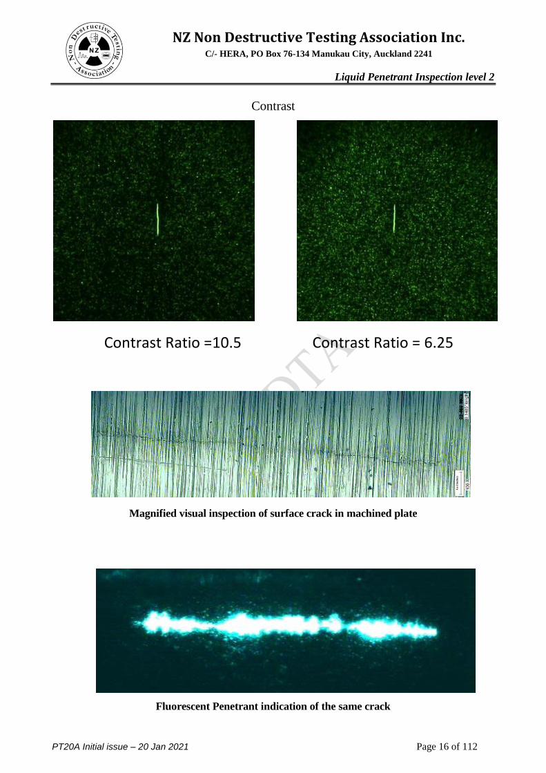
Contrast
Contrast Ratio =10.5 Contrast Ratio = 6.25
Magnified visual inspection of surface crack in machined plate
Fluorescent Penetrant indication of the same crack
Page 17
NZ Non Destructive Testing Association Inc. C/- HERA, PO Box 76-134 Manukau City, Auckland 2241
Liquid Penetrant Inspection level 2
PT20A Initial issue – 20 Jan 2021 Page 17 of 112
1.7 Capabilities of PT
Since penetrant testing produces indications by means of a liquid bleeding out from a discontinuity, it
follows that it can only detect defects which have an opening to the surface into which the liquid can
originally penetrate. Although this is a major limitation, especially when relating to manufacturing
discontinuities, almost all of the surface defects can be detected by this method.
Defects such as; fatigue cracks, shrinkage, porosity, cold shuts, grinding and heat treatment cracks,
seams, forging laps and bursts, welding cracks are all able to be found. In addition, Penetrant testing is
used successfully on all metals in common use as well as many non-metals for example, plastics,
rubber, ceramics and glass.
The penetrant inspection method is not restricted to external applications of liquid and powder
chemicals. For instance, in the testing of wings for fuel leaks the Boeing Company uses ammonia gas
inside the tanks and a specially developed indicator fluid on the outside of the tank. The actual
sensitivity of this process can pick up a leak of l milligram/hour of ammonia which is equivalent to
the leakage of l LB of fuel in 50 years.
Advantages of the PT method
The main advantage of the penetrant method is its simplicity both in principle and application.
However, it must be clearly understood that there are certain rules and principles to be observed if
consistent and reliable results are to be obtained.
Penetrant materials and associated equipment are relatively inexpensive
Indications are produced directly on the surface of the part and constitute a visual
representation of the flaw.
Large areas and large volumes of parts/materials can be inspected rapidly making this a very
economic process
No limitation on the size of or shape of the article to be inspected and parts with complex
geometric shapes are routinely inspected.
Because of the simplicity of equipment and the advent of aerosol spray cans the penetrant method
is extremely portable
The method has few material limitations, i.e. metallic and non-metallic, magnetic and
nonmagnetic, conductive and nonconductive materials may be inspected.
The penetrant fluid having been developed over the years has a remarkable ability to enter
extremely fine cracks. This sensitivity can in the case of fine cracks can give penetrant testing an
advantage over other methods in cases where clarity of indication is of prime importance.
Page 18
NZ Non Destructive Testing Association Inc. C/- HERA, PO Box 76-134 Manukau City, Auckland 2241
Liquid Penetrant Inspection level 2
PT20A Initial issue – 20 Jan 2021 Page 18 of 112
1.8 Limitations
The prime limitation of the method is that only discontinuities that are open to the surface are
detectable by the penetrant method.
Some materials are susceptible to attack by the penetrant liquid and this precludes the penetrant
process from these. However, special penetrants are produced for various materials and in these
eases the problem is overcome e.g. oil-based penetrants will attack rubber, whilst water or
alcohol-based penetrants will not.
The penetrant itself suffers from contamination from foreign material, especially water.
Only materials with a relative nonporous surface can be inspected. However special penetrant
procedures that use the filtered particle technique can be used on very porous material.
Precleaning is critical as contaminants can mask defects.
Metal smearing from machining, grinding and grit or vapour blasting must be removed prior to
LPI.
The inspector must have direct access to the surface being inspected.
Surface finish and roughness can affect inspection sensitivity.
Post cleaning of acceptable parts or materials is required.
Chemical handling and proper disposal is required.
Applications of PT
There are a number of reasons for selecting penetrant inspection over other non-destructive testing
methods. Some of the reasons for choosing penetrant inspection are:
Penetrant inspection, under ideal conditions, can detect very small discontinuities.
Penetrant inspection permits examination of all accessible surfaces of a component in one
operation. Other non-destructive methods cover a specific area or location and must then be
repeated to cover other areas or locations.
Penetrant inspection magnifies the apparent size of discontinuities so the indications may be more
readily detected without optical aids.
Penetrant inspection indicates the location, orientation and approximate length of the indication
directly on the component, making interpretation possible.
The sensitivity level of penetrant inspection may be adjusted through selection of materials and
technique. This allows suppression of indications from small, inconsequential discontinuities
while indicating larger discontinuities of more concern.
The selection of the best penetrant process depends upon:
1. Sensitivity required
2. Number of articles to be tested
3. Surface condition of component being inspected
4. Configuration of test specimen
5. Availability of water, electricity, compressed air, suitable testing area, etc.
The term "sensitivity" when used to describe a penetrant performance characteristic, is the ability to
produce indications from very small, tight cracks. This ability involves both penetrating ability and
brightness
Page 19
NZ Non Destructive Testing Association Inc. C/- HERA, PO Box 76-134 Manukau City, Auckland 2241
Liquid Penetrant Inspection level 2
PT20A Initial issue – 20 Jan 2021 Page 19 of 112
Module 2
Penetrant Properties and Classification
Contents Page
Capillary action 20
Surface Tension, Contact angle and Wet ability 20
Viscosity 23
UV stability, flash point and removability 24
Brightness and Dye Threshold 25
Sensitivity 26
Colour Contrast and Fluorescent Penetrants 27
Classification AMS 2644 Type method sensitivity 28
Developers and solvents 30
Family concept 31
Page 20
NZ Non Destructive Testing Association Inc. C/- HERA, PO Box 76-134 Manukau City, Auckland 2241
Liquid Penetrant Inspection level 2
PT20A Initial issue – 20 Jan 2021 Page 20 of 112
2 Penetrant Properties. The key material in penetrant testing is of course, the penetrant itself. The name penetrate comes from
the most essential property of the material, the ability to penetrate or enter the finest openings or
discontinuities.
The ability to enter fine openings does not come from simply being a liquid of low viscosity i.e. a thin
liquid but from a phenomena called capillary action. Capillary action is the force that causes sap to
rise in trees, kerosene to travel up a lamp wick and ink to be absorbed by blotting paper. The capillary
action force generated by a given liquid in a tube of given diameter and material is a function of a
variety of properties. Two of these being; the surface tension of the liquid and its ability to wet the
surface.
2.1 Surface Tension The surface tension of a liquid is created by the molecular attraction forces within the liquid. Each
molecule creates an attraction force which is felt in all directions around it. By this means the
individual liquid molecules bind together making the liquid one body. This is the property that causes
the surface of a liquid to behave as if it were covered with a weak elastic skin; this is why a needle
can float on water. It is caused by the exposed surface's tendency to contract to the smallest possible
area because of cohesive forces between molecules at the surface
In order for a penetrant to be drawn into small openings by capillary action this liquid should have a
relatively high surface tension
Page 21
NZ Non Destructive Testing Association Inc. C/- HERA, PO Box 76-134 Manukau City, Auckland 2241
Liquid Penetrant Inspection level 2
PT20A Initial issue – 20 Jan 2021 Page 21 of 112
2.2 Wetting Ability
As previously mentioned, one of the important characteristics of a liquid penetrant material is its
ability to freely wet the surface of the object being inspected. At the liquid-solid surface interface, if
the molecules of the liquid have a stronger attraction to the molecules of the solid surface than to
each other (the adhesive forces are stronger than the cohesive forces), then wetting of the surface
occurs. Alternately, if the liquid molecules are more strongly attracted to each other and not the
molecules of the solid surface (the cohesive forces are stronger than the adhesive forces), then the
liquid beads-up and does not wet the surface of the part.
One way to quantify a liquid's surface wetting characteristics is to measure the contact angle of a
drop of liquid placed on the surface of the subject object. The contact angle is the angle formed by
the solid/liquid interface and the liquid/vapour interface measured from the side of the liquid. See
the figure below. Liquids wet surfaces when the contact angle is less than 90 degrees. For a
penetrant material to be effective, the contact angle should be as small as possible. In fact, the
contact angle for most liquid penetrants is very close to zero degrees.
The wetting ability of a Liquid is something that does not depend on the liquid alone, the surface that
it is against being equally important. This can be seen with water, which will wet clean glass easily
but doesn't wet oily glass at all.
Where a liquid has a high surface tension and good wetting ability, then the liquid will be able to pull
itself into the finest gap i.e. .000013" or less, with a force large enough to raise a column of water
30ft.
The following Static Penetrant Performance formula is sometimes used to measure the capillary force
(or pressure) driving the penetrant into the opening. However this does not take into account the size
of the opening and nature of the defect
SPP = r X cos
Where r = Surface tension (Liquid Gas)
= Contact angle (usually given a value of 1 for angles less than 5 degrees
Page 22
NZ Non Destructive Testing Association Inc. C/- HERA, PO Box 76-134 Manukau City, Auckland 2241
Liquid Penetrant Inspection level 2
PT20A Initial issue – 20 Jan 2021 Page 22 of 112
As previously discussed this is only a guide to the penetrants performance as there are many other
properties that will affect the Capillary action needed to ensure a good penetrant
Capillary action is the result of adhesion and surface tension. Adhesion of water to the walls of the
vessel is the result of the contact angle and will cause an upward force on the liquid at the edges and
result in a meniscus which turns upward. The surface tension acts to hold the surface intact, so
instead of just the edges moving upward, the whole liquid surface is dragged upward.
The height h to which capillary action will lift water depends upon the weight of water which the
surface tension will lift:
Illustration of capillary rise and fall.
Red=contact angle less than 90°
Blue=contact angle greater than 90°
Page 23
NZ Non Destructive Testing Association Inc. C/- HERA, PO Box 76-134 Manukau City, Auckland 2241
Liquid Penetrant Inspection level 2
PT20A Initial issue – 20 Jan 2021 Page 23 of 112
2.3 Viscosity.
Viscosity (measurement of a fluid's resistance to flow) has been thought to have an important effect
on penetrability, but this is not necessarily true. Many relatively highly viscous materials have been
found to be good penetrants. It does affect the speed of penetration and as such will determine the
time it takes for the penetrant to enter a defect and also how long it will take for the penetrant to
"bleed out" during the development stage. This is directly related to the Dwell and Development
times within the process and must be strictly controlled in order to achieve repeatable results.
Another consideration for the viscosity of penetrants is the temperature range over which the
penetrant will retain its viscosity rating. Most modern penetrant standards require the viscosity be
maintained below 5 centistokes over a temperature range of 5 to 55 degrees C.
In addition to the above, the viscosity will affect the amount of penetrant that drains off the part
during the dwell step of the process and may require to be re dipped more frequently. This also will
increase drag out losses when moving the part through the penetrant line.
Kinetic Penetrant Performance (KPP) =SPP dived by the Viscosity
2.4 Additional penetrant properties
In addition to the penetrant being able to flow into discontinuities, it must also have 'body' so that it
will stay on the surface of the article during the period of its application. Body will also allow the
penetrant to hold a dye in suspension.
Removability
Removing the penetrant from the surface of the sample without removing it from the flaw is one of
the most critical operations of the penetrant inspection process. The penetrant must be removed
from the sample surface as completely as possible to limit background fluorescence. In order for
this to happen, the adhesive forces of the penetrant must not be so strong that they cannot be broken
by the removal methods used. However, in order for the a penetrant to have good surface wetting
characteristics the adhesive forces, which are the forces of attraction between the penetrant and the
solid surface being inspected, must be stronger than the cohesive forces, which are the forces
holding the liquid together. Proper formulation of the penetrant materials provides the correct
balancing of these forces.
Another consideration in the formulation of the penetrant liquid is that it should not easily become
diluted by the cleaning solution. Dilution of the penetrant liquid will affect the concentration of the
dye and reduce the dimensional threshold of fluorescence.
Flash Point. For safety in use, penetrant materials should have a reasonably high flash point.
Chemical Inertness. Obviously, penetrant materials should not react with the materials on which
they are used. For example, they must not initiate or aggravate corrosion and for parts which will be
exposed to oxygen, the penetrant must be practically inert.
The fluorescence of most dyes is seriously affected by contact with acids. No dye really resistant to
acids is yet available. Chromates and chromic acid also destroy the fluorescence of dyes.
Page 24
NZ Non Destructive Testing Association Inc. C/- HERA, PO Box 76-134 Manukau City, Auckland 2241
Liquid Penetrant Inspection level 2
PT20A Initial issue – 20 Jan 2021 Page 24 of 112
Stability under Changes of Temperature. Since penetrant materials may be shipped, stored, or
used under very wide temperature ranges, their formulations should be such as to prevent separation
or appreciable changes in their operating capabilities.
Specific Gravity. SG of less than 1 is required for dip tanks in order to ensure water contamination
associated with the PE penetrants lies at the bottom of the tank.
2.5 Ultraviolet and Thermal Stability
Exposure to intense ultraviolet light and elevated temperatures can have a negative effect on
fluorescent penetrant indications. Fluorescent materials can loose their brightness after a period of
exposure to high intensity UV light. One study measured the intensity of fluorescent penetrant
indications of a sample that was subjected to multiple UV exposure cycles. After eight exposure
cycles the brightness of the indications was less than one half their original values.
At elevated temperature, penetrants can experience heat degradation or "heat fade." Excessive heat:
1) Evaporates the more volatile constituents which increases viscosity and adversely affects the
rate of penetration;
2) Alters wash characteristics;
3) "Boils off" chemicals that prevent separation and gelling of water soluble penetrants; and
4) Reduces the fluorescence of tracer dyes.
Generally thermal damage occurs when fluorescent penetrant materials are heated above 71C
(160F). It should be noted that the sensitivity of an FPI inspection can be improved if a part is
heated prior to applying the penetrant material, but the temperature should be kept below 71C
(160F). Some high temperature penetrants in use today are formulated with dyes with high melting
points, which improves resistance to heat damage. The penetrants also have high boiling points and
the heat related problems are greatly reduced. However, a loss of brightness can still take place
when the penetrant is exposed to elevated temperatures over an extended period of time.
Penetrant Colour
The colour of the penetrant material is of obvious importance in visible dye penetrant inspection, as
the dye must provide good contrast against the developer or part being inspected. The dye used in
visible dye penetrant is usually vibrant red but other colours can be purchased for special
applications.
When fluorescent materials are involved, the effect of colour and fluorescence is not so
straightforward. LPI materials fluoresce because they contain one or more dyes that absorb
electromagnetic radiation over a particular wavelength and the absorption of photons leads to
changes in the electronic configuration of the molecules. Since the molecules are not stable at this
higher energy state, they almost immediately re-emit the energy. There is some energy loss in the
process causing the photons to be re-emitted at a slightly longer wavelength, which is in the visible
range. Two different fluorescent colours can be mixed to interact by a mechanism called cascading.
Since the human eye is the most commonly used sensing device, most penetrants are designed to
fluoresce as close as possible to the eyes peak response. And that is in the Yellow Green range (550
nm)
Page 25
NZ Non Destructive Testing Association Inc. C/- HERA, PO Box 76-134 Manukau City, Auckland 2241
Liquid Penetrant Inspection level 2
PT20A Initial issue – 20 Jan 2021 Page 25 of 112
2.6 Penetrant Brightness
Fluorescent brightness was once thought to be the only controlling factor with respect to flaw
detection sensitivity. It has recently been established that the dimensional threshold of fluorescence
(discussed below) has just as much influence on the sensitivity as the penetrant brightness. The
amount of brightness associated with a particular penetrant is directly due to the amount and quality
of dye present. As this dye is generally the most expensive part of the penetrant most manufacturers
will only use the minimum required to achieve the sensitivity rating. The process of turning UV
energy into visible light is carried out through dye "Cascading", where several dyes are used to
convert the energy (Activator and Colour forming dyes).
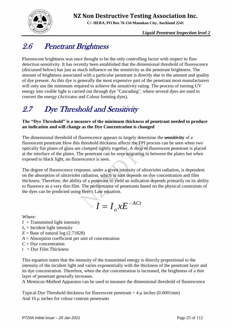
2.7 Dye Threshold and Sensitivity
The ―Dye Threshold‖ is a measure of the minimum thickness of penetrant needed to produce
an indication and will change as the Dye Concentration is changed
The dimensional threshold of fluorescence appears to largely determine the sensitivity of a
fluorescent penetrant How this threshold thickness affects the FPI process can be seen when two
optically flat plates of glass are clamped tightly together. A drop of fluorescent penetrant is placed
at the interface of the plates. The penetrant can be seen migrating in between the plates but when
exposed to black light, no fluorescence is seen.
The degree of fluorescence response, under a given intensity of ultraviolet radiation, is dependent
on the absorption of ultraviolet radiation, which in turn depends on dye concentration and film
thickness. Therefore, the ability of a penetrant to yield an indication depends primarily on its ability
to fluoresce as a very thin film. The performance of penetrants based on the physical constraints of
the dyes can be predicted using Beer's Law equation.
Where:
I = Transmitted light intensity
Io = Incident light intensity
E = Base of natural log (2.71828)
A = Absorption coefficient per unit of concentration
C = Dye concentration
t = Dye Film Thickness
This equation states that the intensity of the transmitted energy is directly proportional to the
intensity of the incident light and varies exponentially with the thickness of the penetrant layer and
its dye concentration. Therefore, when the dye concentration is increased, the brightness of a thin
layer of penetrant generally increases.
A Meniscus-Method Apparatus can be used to measure the dimensional threshold of fluorescence
Typical Dye Threshold thickness for fluorescent penetrant = 4 inches (0.0001mm)
And 10 inches for colour contrast penetrants
ACt
o xEII
Page 26
NZ Non Destructive Testing Association Inc. C/- HERA, PO Box 76-134 Manukau City, Auckland 2241
Liquid Penetrant Inspection level 2
PT20A Initial issue – 20 Jan 2021 Page 26 of 112
Sensitivity and defect size
The nature of the defect can have a large affect on sensitivity of a liquid penetrant inspection.
Sensitivity is defined as the smallest defect that can be detected with a high degree of reliability.
Typically, the crack length at the sample surface is used to define the size of the defect. A survey of
any probability-of-detection curve for penetrant inspection will quickly lead one to the conclusion
that crack length has a definite effect on sensitivity. However, the crack length alone does not
determine whether a flaw will be seen or go undetected. The volume of the defect is likely the more
important feature. The flaw must be of sufficient volume so that enough penetrant will bleed back
out to a size that is detectable by the eye or that will satisfy the dimensional thresholds of
fluorescence.
Example - fluorescent penetrant inspection probability of detection (POD) curve from the
Nondestructive Evaluation (NDE) Capabilities Data Book. Please note that this curve is specific to
one set of inspection conditions and should not be interpreted to apply to other inspection situations
Page 27
NZ Non Destructive Testing Association Inc. C/- HERA, PO Box 76-134 Manukau City, Auckland 2241
Liquid Penetrant Inspection level 2
PT20A Initial issue – 20 Jan 2021 Page 27 of 112
2.8 Colour Contrast and Fluorescent Penetrants The sensitivity and overall reliability of red dye penetrants is lower than the fluorescent penetrants.
Two of the main reasons relate to the relative visibility of the two types of dye and the necessity to
use more developer powder in the case of the red dye materials. The potential difference in
performance between the two types of penetrant is so marked that most of the aviation industry no
longer permits the use of red dye penetrants. Thus, in the case of the commercial industry, the
question then is not one of when should fluorescent penetrants be used but rather one of under what
circumstances might the use of red dye penetrants be tolerated.
The answer to this last question is, "only when the cracks to be detected are relatively wide or when
the surface condition of the part to be inspected is too rough to permit proper inspection using
fluorescent materials".
Small cracks in "bulky" parts, i.e. parts manufactured from rolled plate, forgings or extrusions, may
be very tight due to the restraint imposed by the surrounding material. There may also be residual
stresses in the material serving to close the crack. Such parts should always be inspected using
fluorescent materials.
In the case of structures fabricated from sheet materials, a different situation exists. Because of the
thinness of the sheet material, cracks cannot propagate very far before they have penetrated the
sheet. It is usually true that cracks initiating at fastener holes (the most usual situation) will be
through the sheet before they have propagated out from under the head of the fastener. Once a crack
has propagated through the sheet it is unlikely to be tight and can be detected by a low sensitivity
penetrant such as the red colour contrast penetrant.
The liquid penetrant method is at best marginally better than careful visual inspection of these
structures.
In the general case of structures fabricated from sheet materials visual must accompany the
penetrant inspection.
The second situation in which red dye penetrants may be tolerated relates to the surface condition
of the part. As the surface roughness increases, the excess penetrant becomes more difficult to
remove completely. This can result in an unacceptable background fluorescence. An example of
this would be an aluminium alloy crankcase the surface of which is in an as-sand-cast condition. In
this situation red dye penetrant inspection may be acceptable.
From the above, it can be seen that, although the use of red dye penetrant may be acceptable for
some very limited applications, there is no situation for which a fluorescent penetrant would not be
equally satisfactory or superior.
Page 28
NZ Non Destructive Testing Association Inc. C/- HERA, PO Box 76-134 Manukau City, Auckland 2241
Liquid Penetrant Inspection level 2
PT20A Initial issue – 20 Jan 2021 Page 28 of 112
2.9 Penetrant Classification
Penetrant
Type I Fluorescent dye
Type II Visible dye,
Type III Visible and Fluorescent dye (Dual mode)
Method
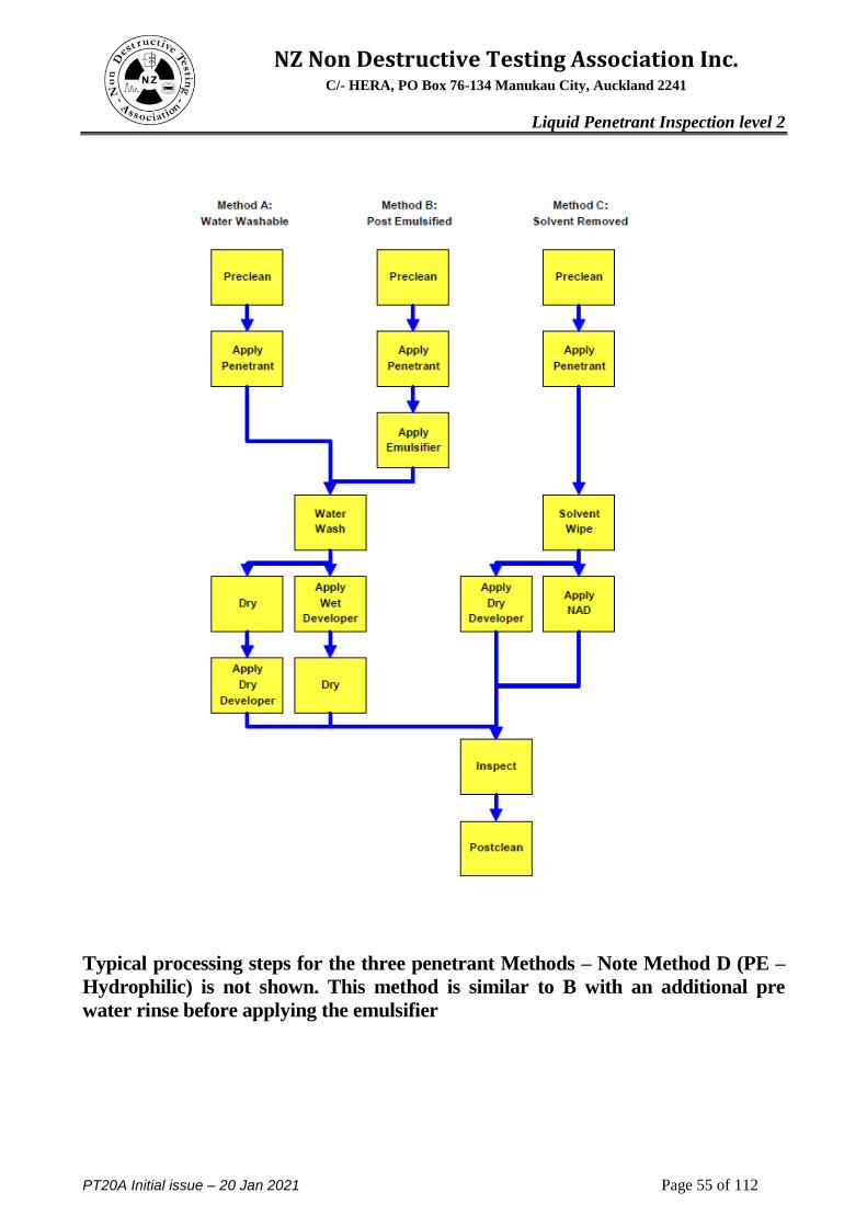
A Water washable
B Post emulsifiable, lipophilic
C Solvent removable
D Post emulsifiable, hydrophilic
Sensitivity
Level l/2 Ultra Low
Level l Low
Level 2 Medium
Level 3 High
Level 4 Ultra high
Developer-
Form a Dry powder
Form b Water soluble
Form c Water suspendable
Form d Non aqueous
Form e Specific application
Solvent Removers
Class(l) Halogenated
Class(2) Non Halogenated
Class(3) Specific application
All penetrant materials do not perform the same and are not designed to perform the same.
Penetrant manufactures have developed different formulations to address a variety of inspection
applications. Some applications call for the detection of the smallest defects possible and have a
smooth surface where the penetrant is easy to remove. In other applications the rejectable defect
size may be larger and a penetrant formulated to find larger flaws can be used. The penetrants that
are used to detect the smallest defect will also produce the largest amount of irrelevant indications.
Page 29
NZ Non Destructive Testing Association Inc. C/- HERA, PO Box 76-134 Manukau City, Auckland 2241
Liquid Penetrant Inspection level 2
PT20A Initial issue – 20 Jan 2021 Page 29 of 112
AMS 2644
Penetrant materials are classified in the various industry and government specifications by their
physical characteristics and their performance. Aerospace Material Specification (AMS) 2644,
Inspection Material, Penetrant, is now the primary specification used to control penetrant materials.
Historically, Military Standard 25135, (MIL-I-25135E,) has been the primary document for
specifying penetrants but this document is slowly being phased out. Other specifications such as
ASTM 1417, Standard Practice for Liquid Penetrant Examinations, may also contain information on
the classification of penetrant materials but they generally refer back to AMS 2644.
AMS 2644 controls the penetrant materials and stipulates certain physical properties of the
penetrant materials that must be met. Some of these requirements address the safe use of the
materials, such as toxicity, flash point and corrosiveness, and other requirements address storage
and contamination issues. Still others delineate properties that are thought to be primarily
responsible for the performance or sensitivity of the penetrants. The properties of penetrant
materials that are controlled by AMS 2644 include surface wetting capability, viscosity, colour,
brightness, UV stability, thermal stability, water tolerance, and removability
Penetrant materials come in three basic types. These types are:
Type 1 - Fluorescent Penetrants
Type 2 - Visible Penetrants
Type 3 - Dual Mode (Visible and Fluorescent)
Fluorescent penetrants contain a dye or several dyes that fluoresce when exposed to ultraviolet
radiation. Visible penetrants contain a red dye that provides high contrast against the white
developer background. Fluorescent penetrant systems are more sensitive than visible penetrant
systems because the eye is drawn to the glow of the fluorescing indication. However, visible
penetrants do not require a darkened area and an ultraviolet light in order to make an inspection.
Visible penetrants are also less vulnerable to contamination from things such as cleaning fluid that
can significantly reduce the strength of a fluorescent indication. There are other types, eg. Type 3
above, which contain dyes which may be used both as colour contrast and fluorescent penetrants.
These are sometimes known as "dual sensitivity" penetrants on the basis that indications of
relatively large discontinuities will be visible under both white and UV illumination while those of
smaller discontinuities will only be visible under UV light
Penetrants are then classified by the method used to remove the excess penetrant from the
part. The four methods are:
Method A - Water Washable
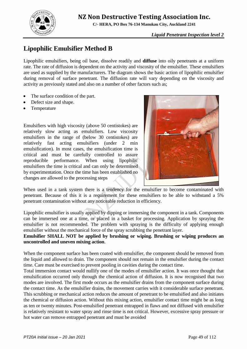
Method B - Post Emulsifiable, Lipophilic (Oil based)
Method C - Solvent Removable
Method D - Post Emulsifiable, Hydrophilic (Water based)
Page 30
NZ Non Destructive Testing Association Inc. C/- HERA, PO Box 76-134 Manukau City, Auckland 2241
Liquid Penetrant Inspection level 2
PT20A Initial issue – 20 Jan 2021 Page 30 of 112
Water washable (Method A) penetrants can be removed from the part by rinsing with water alone.
These penetrants contain some emulsifying agent (detergent) that makes it possible to wash the
penetrant from the part surface with water alone. Water washable penetrants are sometimes referred
to as self-emulsifying systems. Post emulsifiable penetrants come in two varieties, lipophilic and
hydrophilic. In post emulsifiers, lipophilic systems (Method B), the penetrant is oil soluble and
interacts with the oil-based emulsifier to make removal possible. Post emulsifiable, hydrophilic
systems (Method D), use an emulsifier that is a water soluble detergent which lifts the excess
penetrant from the surface of the part with a water wash. Solvent removable penetrants require the
use of a solvent to remove the penetrant from the part.
Penetrants are then classified based on the strength or detectability of the indication that is
produced for a number of very small and tight fatigue cracks. The five sensitivity levels are:
Level ½ - Ultra Low Sensitivity (Colour/Visible Dye)
Level 1 - Low Sensitivity
Level 2 - Medium Sensitivity
Level 3 - High Sensitivity
Level 4 - Ultra-High Sensitivity
The major industry specifications currently rely on the US Air Force Materials Laboratory at
Wright-Patterson Air Force Base to classify penetrants into one of the five sensitivity levels. This
procedure uses titanium and Inconel specimens with small surface cracks produced in low cycle
fatigue bending to classify penetrant systems. The brightness of the indication produced is measured
using a photometer.
The sensitivity levels and the test procedure used can now be found in Aerospace Material
Specification AMS 2644, Penetrant Inspection Materials QPL (Qualified Products List)
Developers The four developer forms listed (specific application is there to cover special, undefined
applications) differ with respect to the way they are used. The names given are self explanatory.
Dry developers are applied to a surface as a dry powder. Water soluble and suspendable developers
are applied by immersing parts in the solution and subsequently precipitating a coating of powder
on the surface by evaporation. The last form listed, non-aqueous, refers to developer powders
suspended in a volatile solvent. These are almost exclusively applied to a surface from an aerosol
can. The solvent, having conveyed the particles to the surface, evaporates quickly to leave a dry
powder coating.
Form a Dry powder
Form b Water soluble
Form c Water suspendable
Form d Non aqueous
Form e Specific application
Page 31
NZ Non Destructive Testing Association Inc. C/- HERA, PO Box 76-134 Manukau City, Auckland 2241
Liquid Penetrant Inspection level 2
PT20A Initial issue – 20 Jan 2021 Page 31 of 112
Solvent Removers Class(l) Halogenated
Class(2) Non Halogenated
Class(3) Specific application
The two classes of solvent removers listed differ only with respect to whether they contain
halogens. The common halogens are chlorine, fluorine, bromine and iodine. It is the first two of
these - chlorine and fluorine - which are present in many solvents (eg. chlorine in trichloroethylene
and fluorine in the freons). If residues of halogens are left on parts made from austenitic
stainless steels or titanium alloys, they may subsequently cause problems with stress corrosion
cracking; particularly if the parts are subjected to high temperatures in service. For this reason,
only halogen free solvents should be used as penetrant removers for these materials. Naturally the
same precaution should be taken in the case of solvents used at the pre-cleaning stage.
There is also a similar problem with contamination of nickel based alloys with sulphur.
Some specifications stipulate tests for corrosive properties which would be difficult to pass for a
material containing significant amounts of sulphur or halogens. Turbine engine manufacturers are
particularly careful and will usually have their own specifications requiring that contaminates in
penetrant materials do not exceed certain limits. A requirement typical of that of a turbine
manufacturer would be sulphur - 0.1% max., sodium 0.01% max., fluorides 50 ppm max., chlorides
1,000 ppm max.
2.10 Family Concept
Each penetrant material's manufacturer has its own formulation for penetrants, Lipophilic emulsifiers
and Hydrophilic removers.
Penetrant and Lipophilic emulsifiers or hydrophilic removers are qualified as a system (Family).
This system consists of very specific materials from the same manufacturer. Additionally, the
hydrophilic removers are qualified at a specific concentration. Therefore, only products that
comprise a system and listed as such may be used together.
Mixing of manufacturers materials from the same manufacturer that are not part of the system will
not provide for optimum performance and, in some cases, this practice will eliminate any chance of
detecting defects, therefore, it should not be done.
Industry has accepted that any manufacturer's developer could be used with combined penetrant and
emulsifier or remover system of another manufacturer. The condition in which developers can be
used is the same for solvent removers
Page 32
NZ Non Destructive Testing Association Inc. C/- HERA, PO Box 76-134 Manukau City, Auckland 2241
Liquid Penetrant Inspection level 2
PT20A Initial issue – 20 Jan 2021 Page 32 of 112
Page 33
NZ Non Destructive Testing Association Inc. C/- HERA, PO Box 76-134 Manukau City, Auckland 2241
Liquid Penetrant Inspection level 2
PT20A Initial issue – 20 Jan 2021 Page 33 of 112
Module 3
PT process steps
Content Page
Surface preparation Alkaline, Acid, detergent, Aqueous, solvent 34
Abrasive cleaning and paint removal 36
Etching 36
Pre cleaning studies 38
Penetrant Selection, WW and PE 39
Penetrant dwell times 41
Penetrant application 44
Contact, Immersion, dip and drain 44
Electrostatic application 46
Penetrant removal 46
WW, PE – Lipophilic and Hydrophilic 47
Immersion and Spray 48
Solvent removable 54
Drying 57
Development Wet Dry and NAWD 58
Developer action and dwell times 59
Developer sensitivity 63
Page 34
NZ Non Destructive Testing Association Inc. C/- HERA, PO Box 76-134 Manukau City, Auckland 2241
Liquid Penetrant Inspection level 2
PT20A Initial issue – 20 Jan 2021 Page 34 of 112
3 Penetrant Inspection Process 3.1 Surface Preparation
The effectiveness of liquid penetrant testing is based upon the ability of the penetrant to enter surface
discontinuities. The part to be tested must be clean and free from foreign matter that may cover or fill
any discontinuities. The cleaning technique used is in each case is determined by the nature of the part
being tested and the type of soil that must be removed.
In this module the word contaminant is used to denote any substance or condition that may invalidate
or interfere with the liquid penetrant inspection - for instance, paint would not normally be looked
upon as a contaminant but it may certainly be so as far as liquid penetrant inspection is concerned.
Contaminants may be divided into three categories as follows;
1 Those that restrict the entry of penetrant into a defect. These may include paint, oils and greases,
water, cleaning solutions and mechanical smearing due to previous rework.
2 Contaminants which may not exclude penetrant but the presence of which may be damaging to
it. These may include acids, alkalis, di chromates, paint removers and other penetrants.
3 Contaminants which may result in confusing indications. These may include corrosion products,
unsealed anodic coatings, surface scratches etc.
Type 1 contaminants are very common and will normally be removed by a selection of cleaning
methods such as: Solvent cleaning, Detergents, Vapour Degreasing and in the case of water by
applying heat. The problem of mechanical surface smearing is discussed later and usually results from
using mechanical cleaning methods such as glass bead peening, shot or sand blasting and blending.
This danger is high for relatively soft metals such as aluminium.
Type 2 contaminants are particularly a problem in the case of fluorescent materials, the
fluorescence of which may be destroyed by contact with acids and alkalis. These are most likely to
be present following chemical treatment such as the use of paint strippers, surface etching,
anodising etc. Dye penetrants can also damage the fluorescence of a fluorescent penetrant.
A good cleaning procedure will remove all contamination from the part and not leave any residue
that may interfere with the inspection process.
Water-Break Test
A water-break test uses water added to the surface of the part to be inspected to assess the
adequacy of the precleaning process. If there is any contamination in the form of oils or other
soils, the water will separate around those areas that are not clean, showing a ―break‖ in the water
surface (Beading).
This can sometimes be noticed during the washing stage of the inspection process. If this is
suspected the part needs to be completely reprocessed including pre cleaning
Page 35
NZ Non Destructive Testing Association Inc. C/- HERA, PO Box 76-134 Manukau City, Auckland 2241
Liquid Penetrant Inspection level 2
PT20A Initial issue – 20 Jan 2021 Page 35 of 112
Alkaline Cleaners
Alkaline cleaners are chemicals which remove contaminants by chemical action such as saponifying
(conversion of fat or oil into soap) or displacement rather than dissolving the contaminants. These
cleaners after lifting/displacing the contaminant can carry it in suspension, it may separate or it may
react with the cleaner to form water soluble soap.
The cleaning is usually carried out in tanks with the fluid at or near its boiling point. The cleaning
action can be quickened by the use of agitation. Following alkaline cleaning the components shall
be thoroughly rinsed to remove all cleaning chemicals and dried.
Acid Cleaning
Solutions of acids or their salts can be used to remove rust, scale, corrosion products and dry soils.
The type of acid and its concentration depends on the component material and contamination to be
removed. Acid cleaners are not effective on oils or greases and must first be removed so that the
acids can react with the scales etc.
Detergent Cleaning
Detergent cleaners are water based chemicals called surfactants which attach themselves to the soil.
The soil and detergent is then washed away by solution agitation, hand wiping or pressure spraying.
Detergent cleaners can be alkaline, acidic or neutral
Refer also to aqueous degreasers
Aqueous Degreasers
Aqueous Degreasers, such as Ardrox 6333 are being used in place of the solvent de greasers because
they are more environmentally friendly. Since these cleaners may be either acid or alkaline in nature,
precautions are taken to ensure that the selected detergent is non corrosive to the specimen. Hot
Detergent cleaning is most effective when accomplished with agitation, though it may also be used
with scrub, rinse and wipe techniques. After detergent cleaning, the specimen is carefully rinsed in
cold water to remove all detergent residue and then dried in a dryer or immersed in a hot water
bath to ―Flash Dry‖
The drying process is very critical as all water must be removed prior to penetrant application.
Vapour Degreasing
Vapour degreasing is the most effective means of pre-test cleaning. The process not only thoroughly
cleans, it also heats the specimen so that after cleaning no moisture remains in discontinuities. When
allowed vapour degreasing is the preferred cleaning method and should be used whenever practicable.
The solvents generally used with these baths evaporate very quickly and are effective in removing
most oil based contaminates found in the aircraft industry.
The toxic nature and ozone depletion properties of most of these solvents have forced the industry
into replacing these with a more friendly process.
Page 36
NZ Non Destructive Testing Association Inc. C/- HERA, PO Box 76-134 Manukau City, Auckland 2241
Liquid Penetrant Inspection level 2
PT20A Initial issue – 20 Jan 2021 Page 36 of 112
Solvent Cleaning
In field operation it is generally necessary to use a hand applied washing solvent. Suitable solvents
are normally supplied as part of the penetrant kit and these should be used and applied liberally while
the part is scrubbed with a bristle brush. Most solvents used today have a trade off between volatility
and being non flammable. Low volatility solvents such as kerosene, and turpentine should be avoided
unless the part can be heated subsequently to remove the solvent from defects. Solvents remaining in
defects will make entry of penetrants less effective. Volatile solvents such as lacquer thinner, clear gas
and spotcheck SKC-HF quickly evaporate but are highly flammable.
Rust and Surface Scale Removal
Rust removers (descaling solutions, either alkaline or acid), pickling solutions (acid), or wire brushing
are used to remove rust and surface scale. Mechanical removal may be performed using a wire brush
or some form of blasting. When this is used there is a possibility of closing surface discontinuities or
filling them with smeared metal.
Descaling solutions are chosen so that they are noncorrosive to the specimen. Regardless of the
method selected for rust and scale removal, after the process is completed the specimen must be
completely clean, dry, and so treated that surface discontinuities are not clogged, filled or
contaminated.
Paint Removal
Most LPI general procedures today require the removal of paint prior to inspection. The exceptions
usually allow the inspection to be performed providing the paint is thin and in very good condition.
Any method of paint removal that does not harm the specimen is satisfactory. Chemical means such
as solvent stripping and dissolving type hot tank stripping are preferred since any mechanical removal
process adversely affects the surface of the specimen. Paint removal using abrasive means such as
blasting and scraping can cause the surface defects to become "closed" due to the smearing of
the metal especially, with soft material such as aluminium. Further processing is required to
remove this material.
Etching
As mentioned above certain mechanical and chemical cleaning processes may tend to close the
discontinuities by peening or smearing of the surface metal. Under these conditions etching may be
required. The etching is accomplished with either an acid or an alkaline solution which is then
neutralised. After neutralisation the article must be water washed and dried or otherwise cleaned to
remove all traces of the etching and neutralising agents.
Some of the cleaning methods that fall into this category are listed below
Shot or Grit blasting.
Blending / Filing / Machining
Plastic Media Blasting above 40psi
Page 37
NZ Non Destructive Testing Association Inc. C/- HERA, PO Box 76-134 Manukau City, Auckland 2241
Liquid Penetrant Inspection level 2
PT20A Initial issue – 20 Jan 2021 Page 37 of 112
Etching metals with acids and alkalis can provide a surface free from minute obstructions such as
smeared metal. The surface is prepared to an acceptably smooth finish and the etching solution
applied. The etchant will attack the grain boundaries first, exposing the granular structure of the metal.
If a crack is present, the edges will become more exposed. Usually a greater reaction will be
noticed in the area of a discontinuity and a dark stain line may accentuate the defect. After washing
the area with water and drying, the surface will now be ready for inspection either by visual methods
or liquid penetrant.
The concentration of the etch solution and the contact times used will determine the amount of
material that is removed. Typically this is between 0.0002" and 0.001"
For most of the common metals, etchants are readily available and instructions for their use should be
rigidly adhered to. Listed below are some common etching solution
Steel Nitric acid and acetic acid.
Inconel Hydrochloric acid and Ferric Chloride – (Cold Ferric Chloride etch)
Titanium Hydrofluoric acid and Nitric acid
Aluminium Hydrofluoric acid and hydrochloric acid or Sodium Hydroxide
Grit blasting causing crack to be ―closed‖
Left Image: Original fluorescent penetrant inspection pattern in a quench cracked aluminium sample.
Centre Image: Fluorescent penetrant inspection pattern after sanding with 240 grit paper.
Right Image: Fluorescent penetrant inspection pattern after etching to remove 0.0003 inch.
Page 38
NZ Non Destructive Testing Association Inc. C/- HERA, PO Box 76-134 Manukau City, Auckland 2241
Liquid Penetrant Inspection level 2
PT20A Initial issue – 20 Jan 2021 Page 38 of 112
Pre Cleaning studies
Due to the critical nature of the Penetrant Inspection and its use in the industry and the changes in
cleaning processes and materials, a number of studies have been carried out to evaluate the
effectiveness of some of the more common cleaning methods. The following is a brief summary of
these studies.
Oil contaminants
Even with the most stringent cleaning processes (Vapour degreasing) it was noted that there was
still a reduction in sensitivity and this was believed to be a result of the incomplete removal of the
contaminant.
Etchants
Acid entrapment from a pre-penetrant etch was shown to have a disastrous effect on the penetrant
inspection, with a reduction in brightness being the result. Careful cleaning of both acid and caustic
etches before penetrant inspection is required.
Residue from Previous Penetrant Inspections
The effectiveness of a penetrant inspection was significantly reduced if the part had been previously
inspected with a different penetrant, although proper pre- and post- cleaning (degreasing) operations
had been performed. This was the case when the previous inspection was performed with a different
fluorescent penetrant or a visible dye penetrant. When the same penetrant system was used for
both inspections, there was no extensive loss in sensitivity when the specimens received the
required pre- and post-cleaning. The study also showed that even the most careful post-cleaning
operations leave some penetrant in the defects.
Repetitive inspections produce greatly reduced indications.
To illustrate the degrading effect of type II penetrant on type I penetrant, mix one percent visible
and 99 percent fluorescent penetrant together and note the almost complete lack of fluorescence
under black light. The red dye acts as an UV filter and stops nearly all fluorescence.
Cleaning solution contamination
Studies have shown that a small amount of solvent, from the Precleaning operation, if left trapped in
a flaw, can also have a drastic effect on the performance of a penetrant.
It is also important that the cleaning process itself does not cause a reduction in penetrant
sensitivity. Some mild alkaline cleaners include sodium metasilicate as an ingredient. Sodium
metasilicate, sodium silicate, and related compounds can adhere to the surface of parts and form a
coating that prevents penetrant entry into cracks.
Aqueous Precleaners used for Penetrant Inspection have also shown that they can have an effect on
the inspection results. Some domestic soaps and commercial detergents impaired detectability. By
forming deposits in the cracks that were difficult to remove. It is recommended that components be
rinsed in water and then thoroughly dried
Page 39
NZ Non Destructive Testing Association Inc. C/- HERA, PO Box 76-134 Manukau City, Auckland 2241
Liquid Penetrant Inspection level 2
PT20A Initial issue – 20 Jan 2021 Page 39 of 112
3.2 Penetrant Selection
As previously discussed penetrants can be divided into several types, dye penetrants and fluorescent
penetrants. In the case of dye penetrants, a dye is dissolved in the liquid penetrant. The colour of the
dye is selected to give a high colour contrast between the developer and penetrant. In fluorescent
penetrants a fluorescent dye is dissolved in the penetrant which when viewed under black light will
emit visible light
These two processes may further be subdivided into three further categories, water washable (WW)
penetrant, post emulsifiable (PE) penetrant, and solvent removable penetrant. The water washable
penetrant contains an emulsifier before being applied to the specimen which allows it to be water
washed immediately after penetrant dwell time has been completed. The post emulsifiable penetrant
does not contain this emulsifier and therefore cannot be removed by water until an emulsifier has been
applied. Solvent removable penetrants are as their name suggests, removable only by the use of
solvents, and these have special application.
Water washable Penetrants
Water-washable penetrant method is the least sensitive of the three methods involving fluorescent
penetrants. The method utilises an oil based penetrant to which has been added an emulsifier, to
make it water washable. After application of the penetrant, the test surface is washed to remove the
surplus penetrant, and a developer is applied. Either a wet or a dry developer can be used. In both
instances, when viewed under black light, any discontinuities in the test surface glow with a bright
yellow-green light against a dark background. The intensity of the fluorescence is related to the
volume of penetrant retained in the surface flaw.
WW Penetrant Advantages
Does not require the application of an emulsifier as a separate operation.
Water is readily available and environmentally friendly as a washing agent
Fewer processing steps than the PE method
Very good for inspecting materials with a rough surface i.e. castings
PE penetrants
Post Emulsification (PE) fluorescent penetrants utilise an oil base penetrant to which a highly
fluorescent dye has been added. As the penetrant does not contain an emulsifier, it has the ability to
seep into very fine surface defects. The surface film of penetrant is made water soluble by the
application of an emulsifier in a separate operation. The sensitivity of the operation can be partially
controlled by proper judgement of the time between the application of the emulsifier and the rinsing
operation.
Careful application of this technique makes possible the detection of shallow scratches, tool marks,
and shallow imperfections that are wider than they are deep. The following is a brief summary of the
advantages of each method
Page 40
NZ Non Destructive Testing Association Inc. C/- HERA, PO Box 76-134 Manukau City, Auckland 2241
Liquid Penetrant Inspection level 2
PT20A Initial issue – 20 Jan 2021 Page 40 of 112
PE Penetrant advantages
High sensitivity for detecting very fine defects.
Controlling emulsifier time reduces the possibility of over washing
Can detect wide shallow defects.
Good for inspecting large batches of parts
Can be automated
Less operator dependant
Solvent removable penetrant. PE penetrants generally fall into the category of being Solvent Removable due to the fact that they can
be removed using a solvent. Solvent removable penetrant inspection is a relatively high sensitivity
process and is used for the detection of stress or intergranular corrosion, but may be used as a general
inspection method on parts where the use of water is unsatisfactory or inconvenient.
A solvent is used to remove the surface film of penetrant, and the developer used is a quick drying, non
aqueous type. This developer, when applied in the form of a fine spray, forms a thin, uniform coating
that provides the highest degree of inspection sensitivity.
This method is very portable with all fluids being able to be contained in aerosol pressurised cans. The
portable kits are useful in field operations, however, when using a fluorescent penetrant, the ambient
white must be reduced to an acceptable level for adequate indications under black light. The
indications are the same as those obtained with other fluorescent penetrant inspection methods.
Penetrant Sensitivity Selection.
Typical defect openings are usually restricted and the volume is such that only a very small amount of
penetrant can be entrapped. The penetrant must enter and exit the flaw with enough dye to produce a
noticeable indication.
Selection of the sensitivity level to be used depends on a number of factors: potential flaw size, width
of opening and volume; component size, shape, surface finish and intended service of the component.
The rule is to use the lowest sensitivity that will reveal the flaws. Difficulties can be experienced if the
sensitivity level is either too low or too high. Low sensitivity levels may not reveal the potential flaws
while excessive sensitivity can result in a background that could obscure any discontinuity indications.
A Type and Size of Potential Flaws. Large flaws, such as those caused by overstress, can be
detected with low sensitivity materials. Small, tight fatigue cracks, such as those occurring in
engine rotating components, require ultrahigh sensitivity materials.
B Surface Condition of the Component. Components with rough surfaces, such as casting, welds
and forged components, tend to retain some of the penetrant. The use of high or ultrahigh
sensitivity penetrants on rough surfaces may produce an excessive residual background that
could obscure potential flaws.
C Material and Process Control Costs. The higher sensitivity materials are considerable more
expensive than lower sensitivity materials. This is due mainly to the increased amount of costly
dye stuffs.
Page 41
NZ Non Destructive Testing Association Inc. C/- HERA, PO Box 76-134 Manukau City, Auckland 2241
Liquid Penetrant Inspection level 2
PT20A Initial issue – 20 Jan 2021 Page 41 of 112
3.3 Penetrant Dwell (Contact) Time
Penetrant contact time is the total length of time from the initial application of the penetrant until
it is removed. This includes immersion and drain times. The purpose of the contact time is to
allow the penetrant to be drawn into and fill any surface discontinuity.
There are a number of factors that influence the length of time required for the penetrant to fill a
discontinuities. Some of these factors are:
a. Width and depth of the void (Defect).
b. Type and sensitivity of the penetrant
c. Component material and form
d. Type of discontinuity
e. Penetrant viscosity
f. Cleanliness or contamination of the void
g. Temperature of the penetrant and part
Defect Size
The time required for a penetrant to enter and fill a surface void depends largely on the width of
the surface opening and depth of the void. Penetrant enters and fills voids with wide openings
more rapidly than those with narrow openings. Very narrow or tight flaws, such as those
associated with fatigue cracking may require 2 to 5 times the length of time needed for a wider
flaw caused by over-stressing. Capillary action is also a function of the width of the void and
appears to increase as the width of the flaw decreases, however this is usually not enough to
reduce the contact times.
The void depth is simply a matter of volume with more time required to fill a deep void.
Penetrant Sensitivity
The type and sensitivity level of penetrants affect the length of penetrant contact. The differences
in contact times are due to the differences in surface tension, contact angle and viscosity of the
various penetrant types and sensitivities.
While viscosities between manufacturers of the same type and sensitivity level vary, the
combination of factors tends to stabilize contact time for each type and sensitivity. This allows
penetrants within each of the sensitivity levels to have equivalent contact times
Component Material
The effect of component material (steel, magnesium, aluminium, etc.) on penetrant contact relates
to the width of the surface opening of the discontinuities. For example: cold shuts in steel casting
tend to have tighter openings than cold shuts in magnesium castings. Discontinuities occurring in
forgings are tighter than in castings and require more penetrating time.
Stainless Steels.
Defects associated with SS are generally finer and tighter. Also Susceptible to stress corrosion
cracking and normally associated with critical applications requiring increased sensitivity and
dwell time.
Page 42
NZ Non Destructive Testing Association Inc. C/- HERA, PO Box 76-134 Manukau City, Auckland 2241
Liquid Penetrant Inspection level 2
PT20A Initial issue – 20 Jan 2021 Page 42 of 112
Contaminated discontinuities
Previously stated, various types of discontinuities differ in the width of the opening. Laps are
tighter than porosity and fatigue cracks are tighter than either laps or porosity. If the discontinuity
is contaminated, penetration cannot occur. A discontinuity that is only partially contaminated will
produce a smaller and less visible indication. Increasing the contact time will not improve the
indication. However, a more sensitive penetrant with its higher dye content will produce a more
visible indication.
When discontinuities contain contaminants that are soluble in penetrants, such' as grease and oils,
the situation is different. The penetrant will fill any vacant space in the discontinuity and then
stop. Diffusion then begins between the penetrant and soluble soil. In a short time, the penetrant
and oil become evenly mixed.
This mixture will fluoresce much less and may not give a useful indication. An increase in contact
time will improve the visibility of the indication.
Using a more sensitive penetrant will also improve the visibility of the indication as the higher dye
content can withstand more dilution and still fluoresce
In summary, when a flaw is partially filled with an insoluble soil, an increase in contact time will not
improve the visibility of the indication. However, if the soil is soluble in the penetrant, the visibility
will improve with increases in contact time. In both cases (insoluble and soluble contamination) a
higher sensitivity penetrant will improve the results.
Additional considerations
Although not specifically mentioned above there are several other considerations that will have an
effect on the time it takes for the penetrant to fill the void
The atmospheric pressure at the flaw opening and the pressure of the gas trapped in the flaw by the
penetrant will change the capillary characteristics of the penetrant. These may not be able to be
controlled by the inspector but depending on the environment and nature of the defect, may reduce
the inspection quality.
Contact Times
The number of factors influencing the entry of penetrant into a discontinuity complicates setting
standard minimum penetrant dwell times. Most contact times are based on past experience with
similar components, materials and potential flaws.
Once the penetrant has completely filled a void, extending the contact time will not improve the
indication, except for contaminated flaws. However, very tight fatigue cracks, flaws in surfaces
under compressive loading, and stress corrosion cracks may require contact times measured in
hours instead of minutes.
It is good practice to apply fresh penetrant at 30 minute intervals when long contact times are
required.
When intermediate contact times, 45 minutes or more, are involved, the fresh penetrant should be
applied 15 minutes before removal. Application of fresh penetrant improves the rate of penetration
and makes it easier to remove the excess surface penetrant at the end of the contact period.
If for some reason the penetrant is allowed to become tacky or dry the component should be
subjected to a complete reprocessing through the pre-cleaning and penetrant inspection cycle.
Page 43
NZ Non Destructive Testing Association Inc. C/- HERA, PO Box 76-134 Manukau City, Auckland 2241
Liquid Penetrant Inspection level 2
PT20A Initial issue – 20 Jan 2021 Page 43 of 112
Temperature Limitations
Penetrant inspection should not be performed when the component temperature is less than 4°C.
There are several reasons for this:
A. At 0°C or less, any moisture, even from the inspectors' breath, will form ice crystals on the
component, which will interfere with the penetration process.
The evaporation rate of solvent cleaners and non-aqueous developers is reduced at lower
temperatures.
B. The viscosity of the penetrant increases as the temperature decreases. When temperatures
are below 16°C and above 4°C, it is recommended that the contact time be increased due to
the increased viscosity.
Penetrant inspection should not be performed when the component temperature is greater than
49°C. The reasons are as follows:
Sensitivity is improved slightly when the test components temperatures are 49°C to 65.5°C. The
higher temperature evaporates some of the liquid which increases the dye concentration and reduces
viscosity which speeds penetration. However, the disadvantages of elevated temperatures
outweigh the advantages. During penetrant contact the layer of penetrant is very thin and with a
component temperature of more than 49°C, the loss of volatile constituents will drastically
change the composition of the penetrant and its capillary action. Additionally elevated
temperatures will reduce visible dye colour and fluorescence (heat fade), making indications less
visible.
Heat fade or permanent loss of fluorescence starts at about 78°C and increases rapidly with
increased temperatures and time. This could mean that fine indications disappear.
Therefore, when drying components in re-circulating ovens etc. the temperature and times must be
very carefully controlled.
Most penetrant manufacturers will specify the temperature range over which their penetrant will
maintain the required viscosity. Generally this will be between 5 and 55 degrees C
Typical minimum penetration times (minutes)
MATERIAL FORM TYPE OF
DISCONTINUITY
LEVEL 2
PENETRANT
LEVEL 3/4
PENETRANT
Aluminium Castings Porosity
Cold shuts
Hot tears
10
15
15
10
10
10
Forgings &
Extrusions
Laps
Bursts 20
20
10
10
Welds Lack of Fusion
Stress Cracks 15
30
10
15
Steel Castings Porosity
Cold shuts
Hot tears
20
20
Not recommended
10
15
20
Forgings &
Extrusions
Laps
Bursts Not recommended
Not recommended
20
20
Welds Lack of Fusion
Stress Cracks 20
30
15
20
All Metals All Forms Cracks
Fatigue cracks
Stress corrosion
20
40
Not recommended
15
30
60
Page 44
NZ Non Destructive Testing Association Inc. C/- HERA, PO Box 76-134 Manukau City, Auckland 2241
Liquid Penetrant Inspection level 2
PT20A Initial issue – 20 Jan 2021 Page 44 of 112
3.4 Penetrant Application
The application of the penetrant can take many forms, the object is to cover the part to be inspected
with a wet film of penetrant. This film is to be kept wet for the entire penetration (dwell) time.
There are numerous ways to apply this penetrant some of the more common are
CONTACT MODES
There are two basic penetrant contact modes:
1 Immersion contact, where the component remains submerged in a tank of liquid
penetrant for the entire contact period.
2. Drain contact, where the component is first covered with penetrant by spraying,
brushing, or immersion. Once coated, the component is placed on a rack or rest and
allowed to drain during the contact period.
IMMERSION CONTACT
Previous theory considered immersion contact to be more sensitive than drain contact. The logic
of this theory was based on the penetrant being more migratory or flowing easier with lower
viscosity when evaporation is reduced. The theory also reasoned that the solvent properties of a
penetrant are based on the lighter petroleum oils. These lighter oils tend to evaporate first and
keeping a component immersed during the contact period improved the solvent action.
DRAIN CONTACT
Laboratory tests have demonstrated the improved performance of drain contact mode compared to
that of immersion contact mode. This improved performance is due to the changes in penetrant
composition that occur during the contact period. The penetrant vehicle is a mixture of heavy oils
which dissolve and hold the dye materials in solution, and thin or lightweight solvents or oils
which reduce the penetrants viscosity
During the drain contact period, the lighter weight liquids evaporate which increases the
concentration of the dye materials entrapped in discontinuities. The increased dye concentration
enhances the visibility if the indication. The drain contact mode is also more economical than
immersion contact mode as the excess penetrant drains from the component and is recovered. The
savings with drain contact is two-fold the drained penetrant is recovered and since the remaining
penetrant layer is much thinner than an immersion contact layer, less emulsifier is required during
removal
As noted above the penetrant must be kept wet during the entire dwell time. This is to ensure the
penetrant does not dry out while keeping a supply of new fluid available to enter any defects.
When applying the penetrant the penetration or dwell time is that time between applying the penetrant
and washing the penetrant off at the wash or rinse stage. This includes any draining time.
Page 45
NZ Non Destructive Testing Association Inc. C/- HERA, PO Box 76-134 Manukau City, Auckland 2241
Liquid Penetrant Inspection level 2
PT20A Initial issue – 20 Jan 2021 Page 45 of 112
Brush Immersion
Spray
Page 46
NZ Non Destructive Testing Association Inc. C/- HERA, PO Box 76-134 Manukau City, Auckland 2241
Liquid Penetrant Inspection level 2
PT20A Initial issue – 20 Jan 2021 Page 46 of 112
Electrostatic Application
Applying penetrant to large components such as fan casings and HPC drums etc, has previously been
carried out by immersion tanks or by conventional air spray. The immersion system involves the
installation of large tanks, which not only occupy valuable floor space but also require large quantities
of materials, necessitating careful control and eventually complete replacement Some of the more
complex components will entrap penetrant in areas from which it is almost impossible to obtain
complete removal, thus increasing cost through "dragout". Conventional air or aerosol spraying
methods have the disadvantage of high material consumption.
To overcome these problems, electrostatic application systems have been developed from the well
known and proved electrostatic method of paint spraying: it combines the desirable features of speed
of application; eliminates the necessity for material control; offers economy in consumption of
material, minimises floor space requirements and ensures complete coverage of the part.
Principles of Electrostatic Spraying
The process is based on the fundamental 'law that electrically charged particles of opposite polarity
attract one another: when these particles are placed within an electrical field they align themselves to
the lines of force of that field. In practice, this electrical field is obtained by creating a potential
difference between the work piece, which is connected to earth, and the hand gun which is connected
to the electrical generator. The negative charge on the particles is produced via a rotating atomiser in
the liquid gun, and by a charged electrode surrounding the nozzle in the powder gun. The result is a
"wrap-round" which allows all shapes of components to be evenly coated front and back with one pass
of the gun. To ensure an adequate coverage the penetrant should be of a relatively low viscosity to
assist in the atomisation. In addition the penetrant should have a high electrical resistance so that it can
accept and retain the charge.
The equipment consists of a D.C. high voltage generator and two pressurised spray units, one for
penetrant and one for developer, each feeding a spray pistol connected to the H.T. supply.
3.5 Penetrant Removal
Following application of the penetrant and elapse of sufficient time for penetration, the penetrant is
removed from the surface of the specimen. This operation, commonly referred to as the "Wash Cycle",
is meant to remove the penetrant from the surface without disturbing any penetrant which has entered a
discontinuity. Adequate removal is necessary to ensure against formation of irrelevant indications or
interfering background.
Confusion can sometimes exist when using the term "Rinse Cycle" to identify this stage of the process.
As discussed below, when removing a post emulsifiable penetrant there are several steps which include
a pre water rinse and a post water rinse.
Several options are available to remove the excess penetrant but the choice of method is mainly driven
by the penetrant itself and whether the inspection is being performed in processing line such as an
engine overhaul shop or a portable inspection out on the job
Within a processing tank line arrangement, the use of water is the preferred option. Water is readily
available, reasonably cheap and environmentally friendly. It is also non-flammable and non-toxic.
In addition, water can easily be controlled by the operator to ensure over and under-washing does not
occur. This will be discussed further below
Page 47
NZ Non Destructive Testing Association Inc. C/- HERA, PO Box 76-134 Manukau City, Auckland 2241
Liquid Penetrant Inspection level 2
PT20A Initial issue – 20 Jan 2021 Page 47 of 112
Water Washable Method A
Water Washable (WW) penetrants have a built in emulsifier and the removal of this type of
penetrant is easily accomplished by a water wash.
The best method of washing is by the use of a hose and spray nozzle. The water Washable Penetrant is
converted into small suspended oil droplets by mechanical force of the water spray. A separate process
step of applying emulsifier is not required. Water Washable penetrants are often called ―self
emulsifying‖ and are the most widely used.
High performance WW penetrants approach the capabilities of the Post Emulsifiable penetrants and
some have been qualified to sensitivity Level 4
The character of the water spray developed is important with care being taken to ensure that the spray
volume and force do not wash the penetrant out of discontinuities. It should be strong and forceful,
and composed of large coarse droplets which cut through the film of penetrant, and then 'roll' it off the
surface. Water with a fine mist would have a higher probability of removing some of the penetrant
trapped in the defects. Some of the other considerations regarding the water wash are listed below
Removal is controlled by length of wash time and must be stopped when an acceptable background is
reached. Water washing of Fluorescent penetrant must be carried out under UV lighting. The
wash station should also be in subdued light were possible.
Reasonably coarse water droplets (not mist or solid stream)
The spray should be applied so that it reaches the surface of the specimen at an angle of
approximately 45 degrees
Water temperature should fall within the range of 100 to 35
0 C (50 to 100 degrees F) with
temperatures being held reasonable constant preferably at the higher end of the range.
A maximum safe water pressure not to exceed 40 pounds per square inch (276 kPa). If the water
is air assisted then the maximum pressure should not exceed 25 psi (170 kPa).
Water spray
Emulsified Penetrant
Page 48
NZ Non Destructive Testing Association Inc. C/- HERA, PO Box 76-134 Manukau City, Auckland 2241
Liquid Penetrant Inspection level 2
PT20A Initial issue – 20 Jan 2021 Page 48 of 112
PE Penetrant Removal Method B and D
Post emulsifying penetrant removal is a two step process because the penetrant does not contain an
emulsifier. When penetration is complete, a coating of emulsifier is applied over the surface as a
separate step. Time is allowed for the emulsifier to mix with the surface film of penetrant, after which
washing with a water spray results in a clean surface. In this case the wash water removes only that
penetrant, which has become impregnated with emulsifier, and prolonged washing will not remove
penetrant in either the fine or the open defects into which emulsifier has not entered. This technique is
especially sensitive for wide shallow discontinuities.
The amount of time that the emulsifier is permitted to remain acting on the penetrant is very critical
and will vary dependent on the type and size of defect. Over emulsification can result in penetrant
being washed from defects particularly those of a shallow nature.
Exact emulsifier dwell time is in accordance with the manufacturer's recommendation and the
technique. The emulsifier may be applied by immersion or spray when allowed by the technique,
however application by brushing is prohibited. Brushing is not recommended because the action of the
brush mixes the emulsifier with the penetrant prematurely and irregularly making control of
emulsification time impossible.
Previously all post emulsifiable penetrants were removed using a Lipophilic or oil based emulsifier.
Recent advancements have given rise to the more popular Hydrophilic or water based emulsifier. The
action and advantages of both these are discussed below. In these notes, the words "emulsifier" will be
used when referring to lipophilic material and the word "Remover" will be used when discussing
hydrophilic material. This is a practice generally used by industry
The Hydrophilic post emulsifiable method (Method D) was introduced in the mid-1970's and since
it is more sensitive than the Lipophilic post emulsifiable method it has made the later method
virtually obsolete. The major advantage of Hydrophilic emulsifiers is that they are less sensitive to
variation in the contact and removal time. While emulsification time should be controlled as closely
as possible, a variation of one minute or more in the contact time will have little effect on flaw
detectability when Hydrophilic removers are used However, a variation of as little as 15 seconds
can have a significant effect when a Lipophilic system is used.
During the removal process that uses an emulsifier care must be taken to stay within the technique
requirements regarding timing, temperature and pressure.
If at any stage these are not adhered to or the operator suspects that the process is not being carried
out correctly, the part shall be re processed from the beginning including pre cleaning.
An example of this could be too much penetrant background indicating a longer emulsification time
is required.
All emulsifier contact times are determined by experience and may vary even between process
shops. Each part shall be processed several times using different emulsification times. The
time selected will be such that a very small amount of penetrant background will still be
evident at the inspection stage. Although this will not interfere with the sensitivity it can be
used to confirm the washing stage has been carried out correctly
Page 49
NZ Non Destructive Testing Association Inc. C/- HERA, PO Box 76-134 Manukau City, Auckland 2241
Liquid Penetrant Inspection level 2
PT20A Initial issue – 20 Jan 2021 Page 49 of 112
Lipophilic Emulsifier Method B
Lipophilic emulsifiers, being oil base, dissolve readily and diffuse into oily penetrants at a uniform
rate. The rate of diffusion is dependent on the activity and viscosity of the emulsifier. These emulsifiers
are used as supplied by the manufacturers. The diagram shows the basic action of lipophilic emulsifier
during removal of surface penetrant. The diffusion rate will vary depending on the viscosity and
activity as previously stated and also on a number of other factors such as;
The surface condition of the part.
Defect size and shape.
Temperature
Emulsifiers with high viscosity (above 50 centistokes) are
relatively slow acting as emulsifiers. Low viscosity
emulsifiers in the range of (below 30 centistokes) are
relatively fast acting emulsifiers (under 2 min
emulsification). In most cases, the emulsification time is
critical and must be carefully controlled to assure
reproducible performance. When using lipophilic
emulsifiers the time is critical and can only be determined
by experimentation. Once the time has been established no
changes are allowed to the processing steps
When used in a tank system there is a tendency for the emulsifier to become contaminated with
penetrant. Because of this it is a requirement for these emulsifiers to be able to withstand a 5%
penetrant contamination without any noticeable reduction in efficiency.
Lipophilic emulsifier is usually applied by dipping or immersing the component in a tank. Components
can be immersed one at a time, or placed in a basket for processing. Application by spraying the
emulsifier is not recommended. The problem with spraying is the difficulty of applying enough
emulsifier without the mechanical force of the spray scrubbing the penetrant layer.
Emulsifier SHALL NOT be applied by brushing or wiping. Brushing or wiping produces an
uncontrolled and uneven mixing action.
When the component surface has been coated with emulsifier, the component should be removed from
the liquid and allowed to drain. The component should not remain in the emulsifier during the contact
time. Care must be exercised to prevent pooling in cavities during the contact time.
Total immersion contact would nullify one of the modes of emulsifier action. It was once thought that
emulsification occurred only through the chemical action of diffusion. It is now recognised that two
modes are involved. The first mode occurs as the emulsifier drains from the component surface during
the contact time. As the emulsifier drains, the movement carries with it considerable surface penetrant.
This scrubbing or mechanical action reduces the amount of penetrant to be emulsified and also initiates
the chemical or diffusion action. Without this mixing action, emulsifier contact time might be as long
as ten or twenty minutes. Post-emulsified penetrant entrapped in flaws and not diffused with emulsifier
is relatively resistant to water spray and rinse time is not critical. However, excessive spray pressure or
hot water can remove entrapped penetrant and must be avoided
Page 50
NZ Non Destructive Testing Association Inc. C/- HERA, PO Box 76-134 Manukau City, Auckland 2241
Liquid Penetrant Inspection level 2
PT20A Initial issue – 20 Jan 2021 Page 50 of 112
PE Penetrant Removal
The above diagram shows how the excess penetrant is removed using
an oil based emulsifier (Lipophilic)
Page 51
NZ Non Destructive Testing Association Inc. C/- HERA, PO Box 76-134 Manukau City, Auckland 2241
Liquid Penetrant Inspection level 2
PT20A Initial issue – 20 Jan 2021 Page 51 of 112
Hydrophilic Remover – Method D
Hydrophilic Removers (Method D) differ from the lipophilic emulsifiers in that they are water
based and very close in chemical composition to detergents. Referred to as "Removers", these
emulsifiers remove the excess penetrant with a mechanical and chemical action, sometimes referred
to as Scrubbing. This Scrubbing action is different than the lipophilic process because no diffusion
takes place. Hydrophilic emulsifiers are basically detergents that contain solvents and surfactants.
The hydrophilic emulsifier breaks-up the penetrant into small quantities and prevents these pieces
from recombining or reattaching to the surface of the part. The mechanical action of the rinse water
removes the displaced penetrant from the part which then allows fresh remover to contact and lift
newly exposed penetrant from the surface.
These emulsifiers are supplied in concentrated form by the manufacturer and are diluted with water
prior to use. The acceptable concentration will be specified by the manufacturer.
Hydrophilic removers consist of water soluble chemicals, usually non-ionic surface active agents
called surfactants. They are supplied as concentrated liquids and are mixed with water either before
or during the removal process. The surface active agent in the remover displaces a small quantity of
penetrant from the surface and prevents it from recombining with the remaining penetrant layer.
Unlike Lipophilic emulsifier, hydrophilic remover is immiscible in penetrant and diffusion does not
occur. All of the removal action takes place at the exposed surface and penetrant just below the
surface is not involved until it becomes exposed. Agitation of the liquid removes the displaced
penetrant and allows fresh remover to contact the remaining penetrant layer
Pre-Rinse
The clean, pre-clean, penetrant and penetrant contact time steps are identical in both the Lipophilic
and hydrophilic methods. However, the processes diverge with the pre-rinse step in the
hydrophilic method. The component is subjected to a plain water spray following the penetrant
contact when using the hydrophilic method. The mechanical action of the water spray removes over
80 percent of the excess surface penetrant, leaving only a very thin layer on the component
This pre-rinse step cannot be used in the Lipophilic process as the oil base emulsifier does not
tolerate water. The pre-rinse reduces the amount of remover consumed and in immersion set-ups,
minimizes contamination of remover due to penetrant carry-over. It also reduces remover contact
time as, in general, contact time is about 50 percent less when the pre-rinse step is used.
The pre-rinse cycle should be similar to that used with the Water Wash penetrant. The objective is
to reduce the amount of surface penetrant, while leaving a thin layer remaining on the component.
Spraying
Hydrophilic emulsifiers, when applied by spraying, function by their detergent and scrubbing (kinetic)
action. As a spray the emulsifier concentrate is metered into the forceful water spray rinse in low
concentrations in the range from 0.1% to 5%. The spray scrubs layer after layer of excess surface
penetrant off the test parts, always providing a fresh solution of detergent and water. The surface-active
agent in the remover helps to displace surface penetrant from the test object surface and prevents its re-
disposition on this surface.
Page 52
NZ Non Destructive Testing Association Inc. C/- HERA, PO Box 76-134 Manukau City, Auckland 2241
Liquid Penetrant Inspection level 2
PT20A Initial issue – 20 Jan 2021 Page 52 of 112
Immersion
In an immersion or dip mode, removal of excess surface penetrant with hydrophilic removers is
accomplished in a tank. Mild agitation separates the displaced penetrant from the part. Concentrations
are generally from 5 to 50% in water. At lower concentrations, such as 5%, the penetrant tolerance of
the hydrophilic emulsifier bath is very low. This can require rather frequent recharging of the tank. At
33% concentration, the tank life of the hydrophilic emulsifier appears maximised. It should also be
pointed out that the hydrophilic emulsifier contact time is directly related to the emulsifier
concentration. Less emulsifier contact time is needed with higher concentrations of emulsifier. This
applies to both immersion and spray applications.
It is also noted that specific remover concentrations are specified by the manufacturer as these
concentrations are used for material qualification per AMS 2644
Experimental determinations are required to establish the correct emulsifier contact time for the
removal of excess surface penetrant. The optimum emulsifier contact time depends upon factors such
as:
1. Emulsifier concentration.
2. Method of emulsifier application (dip or spray).
3. Size of test objects and means for handling them.
4. Shape and surface finish of test objects.
5. Pre rinse operation.
Generally, an emulsifier contact time of 1 or 2 min is adequate for removal of excess surface penetrant
by the agitated hydrophilic remover dip tank. In contrast to the Lipophilic emulsifiers, most of the
penetrant is removed while the test part is in the immersion tank.
Page 53
NZ Non Destructive Testing Association Inc. C/- HERA, PO Box 76-134 Manukau City, Auckland 2241
Liquid Penetrant Inspection level 2
PT20A Initial issue – 20 Jan 2021 Page 53 of 112
The Hydrophilic removers are all water based and can either be used in a
bath or sprayed on as shown in this diagram
Page 54
NZ Non Destructive Testing Association Inc. C/- HERA, PO Box 76-134 Manukau City, Auckland 2241
Liquid Penetrant Inspection level 2
PT20A Initial issue – 20 Jan 2021 Page 54 of 112
Solvent Removable Method C
Solvent removable penetrants are properly removed only by the solvent designated for that particular
penetrant by its manufacturer. Prior to use of the solvent, excess penetrant is wiped from the specimen
with absorbent dry lint free towels. After the excess penetrant has been wiped off, the specimen
surface is cleaned with clean towels dampened with solvent. Solvent is never applied directly to the
specimen since it might wash out or dilute the penetrant in a discontinuity.
Solvent removable method C inspections are considered to be one of the most sensitive techniques.
This is due to a combination of factors such as;
The use of high sensitive penetrants
Non Aqueous spray developers used
The use of a solvent during the removal stage assists with the bleed out process
When fluorescent penetrants are used, the removal stage must be carried out using a black light to
ensure complete removal of the penetrant. For visible dye penetrants the absence of red traces on the
wiping materials ensures complete penetrant removal.
Shown above is the Solvent Removable method used mostly
with the portable Penetrant inspection
Page 55
NZ Non Destructive Testing Association Inc. C/- HERA, PO Box 76-134 Manukau City, Auckland 2241
Liquid Penetrant Inspection level 2
PT20A Initial issue – 20 Jan 2021 Page 55 of 112
Typical processing steps for the three penetrant Methods – Note Method D (PE –
Hydrophilic) is not shown. This method is similar to B with an additional pre
water rinse before applying the emulsifier
Page 56
NZ Non Destructive Testing Association Inc. C/- HERA, PO Box 76-134 Manukau City, Auckland 2241
Liquid Penetrant Inspection level 2
PT20A Initial issue – 20 Jan 2021 Page 56 of 112
Note 1 Use correct cleaning methods
Note 2 Pre rinse only applicable to Method D
Note 3 Soluble wet developer is not recommended for use on critical engine parts
Typical processing steps for method D (AMS 2647)
Page 57
NZ Non Destructive Testing Association Inc. C/- HERA, PO Box 76-134 Manukau City, Auckland 2241
Liquid Penetrant Inspection level 2
PT20A Initial issue – 20 Jan 2021 Page 57 of 112
3.6 Drying
The next stage in the process is generally listed as the Development step, however at some time during
the development the part has to be dried. This drying will be performed either prior to or following the
developer application. If the developer to be used is dry powder or non aqueous then the part shall be
completely dry before the developer is applied. When wet developer is used, the specimen is dried after
the developer has been applied.
Prior to drying a visual inspection for pooled water is advisable. These areas will take substantially
longer to dry and may also produce water spots that can be evident during the inspection stage.
Pooled water remaining on the part after the water wash stage can be removed by:
Blotting with a clean lint free towel
Using air with a max pressure of 25 psi (170 kPa)
Rotating or re positioning the part
Using a hot air dryer
Any means of drying that does not interfere with the test process by overheating, or by contamination
of materials, is acceptable but, controlled drying at even regulated temperatures is preferred. A
thermostat controlled forced air dryer with a maximum temperature of 71 degrees C is usually
employed in stationary test installations. Drying should be carried out as quickly as possible in
order to dry the surface of the specimen without affecting the penetrant in the discontinuities.
Some techniques call for the part to be dried within 20 to 30 minutes maximum. During this time the
part may need to be turned and wiped with towels in order to achieve these times.
Hot air guns can be used but are not recommended due to the lack of control regarding temperature and
air pressure
Typical air dryer cabinet with temperature and timing gages
Page 58
NZ Non Destructive Testing Association Inc. C/- HERA, PO Box 76-134 Manukau City, Auckland 2241
Liquid Penetrant Inspection level 2
PT20A Initial issue – 20 Jan 2021 Page 58 of 112
3.7 Development Form a Dry powder
Form b Water soluble
Form c Water suspendable Wet Developers
Form d Non aqueous wet (NAWD)
Form e Specific application
Because penetrant commences to bleed out of discontinuities immediately following removal of
surface penetrant, developer is applied to the specimen as soon as possible after the penetrant removal.
Developer assists in the detection of penetrants retained in discontinuities by aiding in the capillary
process (the developer acts as a blotting agent), and by effectively enlarging the indication. This
happens because the developer causes the penetrant from the discontinuity to spread out over a greater
area. It also serves as a contrasting background for the visible dye processes. In addition Developers
improve the visibility of fluorescent indications by reducing reflections and providing a blue-black
background for the yellow-green penetrant indications
Developer is available in both dry and liquid forms and the selection of developer is in accordance with
the manufacturers recommendation for the type of penetrant and technique used. When a dry or non
aqueous developer is used the specimen must be completely dry before the developer is applied. When
a wet developer is used it is applied immediately after the penetrant removal is accomplished, and the
specimen is then dried.
In the case of Fluorescent penetrants there is evidence to show that in addition to the widening effect,
there is an additional increase in the brilliance of the fluorescence of the penetrant when it is dispersed
in the developer. The dry developer coating can be considered to be made up of very small spherical
particles which are non absorbent. These individual particles may clump together in aggregates of 50 to
100 microns in diameter. It is considered that the penetrant is drawn by capillary action and spreads
around the surfaces of the individual developer particles, without necessarily filling the spaces between
them. Thus the eye will not only see the fluorescent light from a thin film of penetrant in the top layers
of the developer but also the light from many small films of penetrant scattered throughout a
comparatively large volume of developer. With many multiple reflections within the layer this will
produce a significant increase in the brilliance of the indication
Page 59
NZ Non Destructive Testing Association Inc. C/- HERA, PO Box 76-134 Manukau City, Auckland 2241
Liquid Penetrant Inspection level 2
PT20A Initial issue – 20 Jan 2021 Page 59 of 112
Developer Action
Self -development is the formation of an indication without the application of a developer. All
penetrants are capable of some degree of self-development as they will exude from a discontinuity and
spread over the surface. The critical factor is the size and volume of the discontinuities that must be
detected. A relatively large volume of entrapped penetrant is required and self-development is not
reliable in detecting small tight flaws.
One of the principal modes of developer action involves adsorption and absorption. Adsorption
refers to the collection of a liquid on the outer surface of a particle due to adhesive forces. Absorption
refers to the blotting action that occurs when a liquid merges into an absorbent particle. The
mechanism of development is a combination of both adsorption and absorption.
Developer Particles
THE EFFECTS OF A DEVELOPER
Page 60
NZ Non Destructive Testing Association Inc. C/- HERA, PO Box 76-134 Manukau City, Auckland 2241
Liquid Penetrant Inspection level 2
PT20A Initial issue – 20 Jan 2021 Page 60 of 112
Dry Developer
Dry developers are a loose fluffy talcose powder with high absorbent properties and a low bulk
density. They adhere loosely to the surface of a component and are difficult to retain on highly
polished surfaces. However, once an indication begins to form, the developer powder wetted with
penetrant adheres well. At the inspection stage the excess developer on the surface is removed
leaving only that which is associated with an indication. This results in the one big advantage of
dry developer, which is that it is not possible to apply too much developer and mask
indications for that reason.
Dry developers can be applied in many ways. The two most common are by immersing the part
completely in a container of developer powder, or by using a ―cloud chamber‖ consisting of a
sealed container with a layer of powder at the bottom. This powder is agitated by air jets to form a
cloud which settles over the part. Additionally the developer can be injected into the chamber using
a pressurised developer supply. Once the required time has elapsed an extraction system removes
the unused developer prior to opening the chamber. As this technique uses new developer each time
there is no need to regularly check the powder for contamination.
Dry powder developer is generally considered to be the least sensitive but it is inexpensive to use
and easy to apply. The goal is to allow the developer to come in contact with the whole inspection
area, but in most cases this is difficult to achieve unless the electrostatic method is used. Also dry
developers do not provide a uniform white background as some other forms of developers do. This
contrasting background is very important when using visible penetrants, so the use of dry powder is
not recommended under these conditions.
Dry powder developers can be applied by:-
1. Blowing the powder on with a bulb type blower.
2. Immersing the component in a container of powder.
3. Pouring powder over the component.
4. Using a dust or fog chamber where the particles are blown into an air suspension.
5. Spraying with an electrostatic system or low pressure gun
After application, the excess developer should be shaken off or removed with air. The developer
particles are very loosely held and can be easily removed. Wiping, brushing or compressed air in
excess of 5 psig should not be used. Care must be taken to prevent contamination of the dry
developer. The two most frequent contaminants are water or moisture and penetrant. Water in dry
developer comes from components that have not been completely dried or from careless splashing
during the wash step. Water or moisture contamination will cause the dry developer to form lumps
or to cake, thus reducing its effectiveness. Penetrant contamination occurs when particles of
penetrant-soaked developer fall from poorly washed components or heavy indications. Penetrant
contamination will cause false indications either on the component being processed or on
subsequent components.
Page 61
NZ Non Destructive Testing Association Inc. C/- HERA, PO Box 76-134 Manukau City, Auckland 2241
Liquid Penetrant Inspection level 2
PT20A Initial issue – 20 Jan 2021 Page 61 of 112
Wet Developers
Wet developers generally come in one of two forms, water soluble and water suspendable. With
both forms the developer is applied immediately after the penetrant removal step while the part is
still wet. Drying then takes place to evaporate the water to leave a uniform developer coating. These
developers, due to the water, contain both wetting agents and inhibitors. The wetting agents are
used to assist the flow of the water and the inhibitors are to reduce the risk of corrosion.
These wet developers are not recommended for use with the water washable penetrants as some of
the penetrant entrapped in a defect could be removed during the development stage.
Water Soluble
As the name implies, water soluble developers consist of a group of chemicals that are dissolved in
water and form a developer layer when the water is evaporated away. The best methods for
applying water soluble developers are by spraying or dipping. Drying is achieved by placing the wet
but well drained part in a recalculating warm air. If the parts are not dried quickly, the indications
will be blurred and indistinct. Properly developed parts will have an even, pale white coating over
the entire surface.
Water Suspendable
Wet developer is a suspension of absorptive white powder in water. The mixture is prepared in
accordance with manufacturers' directions and is mildly agitated prior to and during use so that the
powder remains evenly distributed throughout the water vehicle. This developer is normally applied by
immersion or spraying. This is a fast and effective method that is well suited for use in rapid,
production line and automatic testing. Wet developer is applied so as to form a smooth even coating,
and particular care is taken to avoid concentrations of developer in dished or hollowed areas of the
specimen. After wet developer has been applied the specimen is thoroughly dried, as above.
Non Aqueous Wet Developer (NAWD)
Non-aqueous developers are suspensions of developer powder in a solvent. They are supplied ready
packed in an aerosol container and are applied to the surface by spraying. The solvent used is highly
volatile so that the developer wetted with solvent appears grey when first applied but quickly changes
to white as the solvent evaporates at ambient temperatures.
Non-aqueous developers are generally accepted as offering the highest test sensitivity. The reason for
their high sensitivity is that the solvent carrier mixes with the penetrant in the crack reducing the
viscosity and initiating the capillary action required to form an indication. Also, in many cases where
tight, small flaws occur, the dry and aqueous developers do not contact the entrapped penetrant. This
results in the failure of the developer to create the necessary capillary and surface tension forces that
serve to pull the penetrant from the flaw.
The solvents are carefully selected for their compatibility with the penetrants. These developers also
contain surfactants and dispersants whose functions are to coat the particles and reduce their tendency
to clump or agglomerate.
Page 62
NZ Non Destructive Testing Association Inc. C/- HERA, PO Box 76-134 Manukau City, Auckland 2241
Liquid Penetrant Inspection level 2
PT20A Initial issue – 20 Jan 2021 Page 62 of 112
Non aqueous wet developers are always applied by spraying. When applying the developer coating it is
essential that it not be applied too thickly. The aerosol should be applied in much the same way as
spray painting. The first pass should provide only a very light coating which is added to by subsequent
passes. The optimum coating to achieve with Fluorescent penetrants is one that still just shows the
metallic lustre of the surface through the penetrant layer. When using fluorescent penetrants, a
developer coating which appears completely white is too thick. When applying this developer with
Visible Penetrants the coating should be thick enough to just obscure the metallic surface and supply a
contrasting background
It can be seen that given a choice, these non-aqueous developers have the advantage of being the most
sensitive, are convenient to use and are packaged so that they cannot be contaminated. They also
produce a contrasting background, making them suitable for both fluorescent and visible penetrant
inspection.
Developer Dwell Time
Extraction of the penetrant entrapped in a flaw is a function of time and volume of available
penetrant. Time must be allowed for the developer to assist in drawing some of the entrapped
penetrant from the flaw and spreading it on the component surface to form the indication. The
length of developing time varies widely with a number of influencing factors. The development
time should be at least one-half of the penetrant contact time and should not start until component is
completely free of moisture.
Over development, i.e. too long a development time, is possible and must be avoided. Developer
action starts when the developer is completely dry and continues until all of the available penetrant
is extracted. An indication will gradually form, reach a maximum resolution point and then begin to
degrade. The lateral diffusion of penetrant over a period of time can be so great that the indication
becomes indistinct. Medium size or large discontinuities will appear as a smear or blob of penetrant.
Small indications are especially critical since the small amount of penetrant may not be observed
when it diffuses.
Standard developer minimum dwell time of 10 minutes is normally acceptable (ASTM E 11417)
and the maximum times vary by developer (1 hour NAWD and 2 to 4 hours for dry)
Page 63
NZ Non Destructive Testing Association Inc. C/- HERA, PO Box 76-134 Manukau City, Auckland 2241
Liquid Penetrant Inspection level 2
PT20A Initial issue – 20 Jan 2021 Page 63 of 112
Comparison of Developers
The relative sensitivities of penetrant inspection with various forms of developer are influenced by a
number of factors. The method of applying the developer produces a range of sensitivities for each of
the developer forms. The table below lists some of the common forms of developer and their respective
estimated sensitivities
Non Aqueous Wet
(Solvent suspended) Spray Most sensitive
Water Soluble Spray
Water Suspended Immersion
Water Soluble Immersion
Dry Powder Electrostatic spray
Dry Powder Fluidized bed
Dry Powder Air Agitated Dust Cloud
Dry Powder Dip and Pour Least sensitive
Page 64
NZ Non Destructive Testing Association Inc. C/- HERA, PO Box 76-134 Manukau City, Auckland 2241
Liquid Penetrant Inspection level 2
PT20A Initial issue – 20 Jan 2021 Page 64 of 112
Page 65
NZ Non Destructive Testing Association Inc. C/- HERA, PO Box 76-134 Manukau City, Auckland 2241
Liquid Penetrant Inspection level 2
PT20A Initial issue – 20 Jan 2021 Page 65 of 112
Module 4
Lighting and Equipment
Contents Page
Lighting 66
Inspection Area 66
Electromagnetic Spectrum 67
Fluorescence 68
Black – UV light 69
LED and Mercury Bulbs 70
Dark adaption 72
Visual Acuity 73
Portable, stationary equipment and automation 74
Page 66
NZ Non Destructive Testing Association Inc. C/- HERA, PO Box 76-134 Manukau City, Auckland 2241
Liquid Penetrant Inspection level 2
PT20A Initial issue – 20 Jan 2021 Page 66 of 112
4 Lighting
After the appropriate development time has elapsed the parts are inspected. Visible dye (colour
contrast) penetrants require good white light conditions, however, where fluorescent penetrants are
used the parts are inspected with high intensity black light in a darkened area or booth. Small parts
may be held under a fixed light. A portable hand light should be used over the surface of large parts.
When using florescent penetrants the indications will glow with a bright yellow/green colour when
scanned with a black light. The extent of the fluorescent indication is generally a function of the size of
defect and the time since developer application. Porosity, blowholes, etc. will show as circular spots,
while cracks, cold shuts and hot tears will generally show as continuous or dotted lines.
Where large defects have retained a quantity of penetrant the indications will spread extensively on the
surface. Experience in the use of the method allows interpretations to be drawn from the extent of this
spread as to the relative size of the defects.
4.2 Inspection Area
The area where final fluorescent inspections are performed must have a low level of visible
(ambient) light in order to maximise the contrast of fluorescent indications. Most specifications
stipulate a maximum background of visible light of 20 lux (2 foot-candles). Ideally, total darkness
would provide the maximum contrast. However, some visible light is required in order to be able to
see the parts and find one's way about the area. Once time has been allowed for the eye to accustom
itself to the darkened area, it will be usually found that the blue/violet light emitted by the black
light lamps will be sufficient for practical purposes.
The inspection area must also be free from distracting reflective surfaces and from fluorescent
materials. For this reason, it should be isolated from the area where the fluorescent penetrant
materials are used. Hands should also be clean as fluorescent contamination of the hands is very
common after processing parts through the inspection process.
A common way to reduce the ambient light when performing a portable fluorescent inspection is to
use a black cap. ,This may be draped over the inspector and surrounding area during the :inspection
stage of the procedure.
The use of visible penetrants requires a well lit inspection area usually with a minimum of 1000 lux
(100 foot candles).
Page 67
NZ Non Destructive Testing Association Inc. C/- HERA, PO Box 76-134 Manukau City, Auckland 2241
Liquid Penetrant Inspection level 2
PT20A Initial issue – 20 Jan 2021 Page 67 of 112
4.3 Electromagnetic Spectrum
The visible spectrum is that part of the electromagnetic spectrum approximately encompassed by the
wavelengths 700 nanometers (x 10-9
m) at the red end to 400 nanometers at the violet end. (previously
known in terms of Angstrom units – x 10-10
m). These electromagnetic radiations, when combined,
form white light which travel at a speed of 300 meters/sec in a straight line until it meets the surface
bounding a new medium. Here it may be reflected, absorbed or transmitted.
Ultraviolet radiation is an electromagnetic radiation whose wavelengths range between X-rays and
visible light. The ultraviolet range is divided into three bands of the following spectral ranges:
a. UV-A 315nm to 400nm. (This is commonly referred to as "Black Light").
b. UV-B 280nm to 315nm.
c. UV-C 100nm to 280nm.
The fluorescent dyes in the penetrants fluoresce most brilliantly at approximately 550nm when
irradiated with black light. Suitable black lights produce energy at a wave length of approx. 365
nm. This light is between the visible and ultra violet in the spectrum. Light in this range is
noninjurious to the skin or eyes.
Page 68
NZ Non Destructive Testing Association Inc. C/- HERA, PO Box 76-134 Manukau City, Auckland 2241
Liquid Penetrant Inspection level 2
PT20A Initial issue – 20 Jan 2021 Page 68 of 112
4.4 Fluorescence
Fluorescence is the property of a material to absorb electromagnetic radiation of a particular
wavelength and the re-emission of the electromagnetic radiation of a greater or visible wave length and
is dependent upon the atomic structure of the fluorescent material and the energy level or wavelength
of the radiation source.
The basic component of all matter is the atom which consists of protons, neutrons and electrons. The
protons and neutrons form a positively charged nucleus while the negatively charged electrons
circulate in orbits around the nucleus. The orbits are not random but are restricted to shells of discrete
energy levels with a definite number of electrons in each shell. When a short wavelength photon (UV
or X-ray) hits an electron in an atom of fluorescent material some of the photons energy is transferred
to the electron which knocks it from its natural shell. This is an abnormal condition for the electron and
atom so the displaced electron returns to its natural shell. The excess energy obtained from the photon
during displacement is released as electromagnetic radiation. The released radiations wavelength is
always longer than the exciting radiation. Each type of fluorescent material emits a specific wavelength
ranging from violet (400nm) to red (700nm).
SOURCES OF ULTRAVIOLET ENERGY
There are several methods of generating ultraviolet light. Three of these are:
a. Low pressure fluorescent tubes.
b. High pressure, mercury vapour bulbs.
c. LED’s
LOW PRESSURE FLUORESCENT TUBES
These are similar to the standard fluorescent tubes used in house hold lighting, but instead of an inert
gas the tube contains metallic mercury. When an electrical current is applied, the mercury vaporises
and emits an ultraviolet radiation with a wave length of approximately 254nm. As this wave length is
of no use in non-destructive testing to excite fluorescent dyes, the inside of the tube is coated with a
phosphor. The phosphor is excited by the ultraviolet radiation and emits wave lengths in the range of
320nm to 440nm.
The amount of ultraviolet light at 365nm wavelength is small compared to the harmful short
wavelength radiation and the visible light emitted from the tube. The short wavelength and visible light
can be removed by making the tube from cobalt glass (Kopp 41). While this removes all undesired
wavelengths it also reduces the 365nm wavelength making it unsuitable for inspection purposes. Also
the tube cannot be easily focused so its intensity per unit area is very low.
These tubes can normally be found in areas where a high UV intensity is not required e.g. Washing
station and general overhead lighting
Page 69
NZ Non Destructive Testing Association Inc. C/- HERA, PO Box 76-134 Manukau City, Auckland 2241
Liquid Penetrant Inspection level 2
PT20A Initial issue – 20 Jan 2021 Page 69 of 112
Black Light
The source of the black light used in liquid penetrant inspection is usually a high pressure mercury
vapour lamp, the essential elements of which are shown in the Fig. The mercury arc is drawn
between electrodes E1 and E2 in the quartz tube Q. Es is a starting electrode in which the starting
current is limited by the resistor R. The whole is enclosed in the outer glass bulb B. When the lamp
is first turned on, the mercury arc is not set up at once. A small low current arc is first set up
between E1 and Es bringing about sufficient vaporisation of the mercury to start the arc between the
main electrodes. This starting process takes about five minutes. Therefore, no attempt should be
made to use the lamp until this starting process is complete and the output is up to the maximum -
about ten minutes should be allowed after first switching on, but specific times will be specified by
the procedure.
These lamps are relatively sensitive to mains
fluctuations and the arc will collapse if the
voltage deviates outside a narrow band. The arc
will not be re-established until the lamp has
cooled down. For this reason, lamps should be
connected to a lighting circuit rather than a
power circuit subject to sudden power demands
from heavy equipment. The most widely used
lamps are the 100 watt spot lamps. These lamps
focus the black light, giving maximum intensity
over a relatively small area.
Mercury vapour lamp
The mercury vapour lamp emits radiation over a large range of wavelengths as shown so it is
therefore necessary to filter out much of the radiation. This is done by using a filter (usually a Kopp
41 type). This permits the transmission of the useful black light peaking at 365 nm. It is this
radiation which causes the penetrant to fluoresce. The filter also permits some radiation of
wavelengths over 400nM to be transmitted. This is visible light in the blue/violet part of the visible
spectrum - those familiar with UV lamps will be aware that a low level of such light is always
present. This visible light is of insufficient intensity to interfere with the perception of indications
and can be eliminated by wearing filtered UV glasses. (increasing the contrast). The filter also
eliminates the transmission of short wavelength black light in the 310-340 NM range. This is good,
since prolonged exposure to radiation in this range can damage the eye.
From the above it can be seen that the high pressure mercury arc bulb is best suited for non-
destructive testing uses. The bulb has a good output at a reasonable distance, they can be focused, to
increase their intensity on a localised area. Also bulbs range from a 2 watt pencil type, to a 400 watt
floodlights
Page 70
NZ Non Destructive Testing Association Inc. C/- HERA, PO Box 76-134 Manukau City, Auckland 2241
Liquid Penetrant Inspection level 2
PT20A Initial issue – 20 Jan 2021 Page 70 of 112
UV-A FILTERS
The glass filter almost universally used, to remove practically all the visible light and all the
radiation whose wavelength is below 315nm, is cobalt/woods glass which has been designated
woods glass or "Kopp 41". The colour of the cobalt glass is a dense red-purple. The surface of the
filter may be smooth or fluted; the fluted surface gives a slightly larger focused spot than the
smooth surface filter.
The Filter transmission curve peaks at 365nm with a small amount of visible violet light also
transmitted. This violet light is not undesirable since it allows the inspector to see the objects in the
immediate vicinity of the ultraviolet source and therefore facilitates the handling of parts during
inspection.
It is important that the casing of the lamp and the condition of the filter is such that none of this
radiation escapes - DO NOT USE A CRACKED FILTER. Provided that only black light in the
desired range is transmitted, there is no danger of harming the eye of the operator. However,
looking directly into the lamp is not recommended. The reason for this is that the aqueous humor in
the eye contains a substance which will fluoresce under black light causing a blurring of the vision.
This effect, although unpleasant, is quite harmless. However, blurred vision is not conducive to
good inspection and if an inspector inadvertently looks directly into the lamp, sufficient time for
vision to return to normal should be allowed before continuing with the inspection. The parts being
inspected may themselves be highly reflective. It is therefore important that direct reflection of the
black light into the eye is avoided. This is not usually a problem using a hand-held lamp since the
natural thing to do is to hold it to the side at an angle to the part in order that it does not obstruct
vision. For the same reasons, highly reflective surfaces in the inspection area should be eliminated -
usually by being painted black.
ULTRAVIOLET INTENSITY VARIABLES
All black lights should be checked daily and after bulb replacement. The minimum acceptable intensity
is 1000 micro watts/cm2 measured at a distance of at least 38 cm (15 inches) from the front face of the
filter.. Care should be taken to see that this filter is clean and that there is not a film of dust on either the
filter or the bulb. Damaged or dirty reflectors or filters shall be replaced or corrected as appropriate.
A lower than optimum intensity may seriously affect the inspection results. Several of the reasons for
intensity variations are as follows:
1 Aging and use (switching on and off) will reduce the effectiveness of the arc and the intensity
will gradually decrease to an unacceptable level
2. New bulbs may vary by as much as 50% in their output. This means that with two new bulbs of
the same type and manufacture, one may have the intensity that is half the other without being
defective.
3. The Ultraviolet intensity varies almost linearly with the line voltage. Below a certain voltage, the
lamp will not sustain the mercury arc and the lamp will extinguish. The light will not restart until
the bulb has cooled. Ultraviolet lamps should be connected to a stable power supply, to alleviate
this problem.
Page 71
NZ Non Destructive Testing Association Inc. C/- HERA, PO Box 76-134 Manukau City, Auckland 2241
Liquid Penetrant Inspection level 2
PT20A Initial issue – 20 Jan 2021 Page 71 of 112
LED UV lights
Recent advancements in the production of UV lights sources have seen the LED (Light Emitting
Diode) emerge as the most efficient source and will soon replace most electrical discharge lamps.
The LED lights can produce very high intensities but can also produce ―white‖ light that must be
monitored to ensure this does not interfere with the inspection.
Other considerations, such as light uniformity, edge drop-off and maximum intensity should also be
addressed when using LED light from different manufacturers. Ref ASTM E3022
LED Battery powered torches should be checked for their output intensity at the beginning and end
of the inspection iaw standard requirements (ASTM E 1417)
Photo-sensitive spectacles - i.e.. the type that darken when exposed to sunlight - must not be worn
when performing an inspection. It is the UV radiation in sunlight that cause the darkening process
to occur. Therefore the black light radiation from the lamp will also cause a darkening of the
spectacle lens, decreasing the ability to perceive the presence of indications
Page 72
NZ Non Destructive Testing Association Inc. C/- HERA, PO Box 76-134 Manukau City, Auckland 2241
Liquid Penetrant Inspection level 2
PT20A Initial issue – 20 Jan 2021 Page 72 of 112
4.5 Dark Adaption
When using fluorescent penetrant, allowing time for the eye to accustom itself to the darkened area
was mentioned above. This is important as it is necessary to allow the eye to increase the size of the
iris to allow more light in. It should also be appreciated that the mechanism of sight is different
under bright light and low light conditions. Under bright light, the eye utilises photopic vision
which allows it to perceive small differences in colour and contrast. In darkness, scotopic vision is
utilised permitting the perception of small light sources but with very reduced colour/contrast
perception. There is also an intermediate light level at which the eye is not very efficient at
perceiving anything - this explains that dangerous time on the roads between daylight and night-
time conditions. In the case of fluorescent penetrant inspection, it is essential that the eye becomes
completely adapted to the very low light level in the inspection area if small indications are to be
found. Complete adaptation of both iris size and mechanism of vision can take up to 20 minutes.
However, sufficient adaptation for the purpose of black light inspection will usually be achieved
with 1 to 5 minutes. Most specifications require a 5 minute dark adaption time, which should also
be adhered to when turning on the white light for interpretation.
The three curves in the figure show
the response of an average human
eye to various amounts of ambient
light. The shift in sensitivity occurs
because two types of
photoreceptors, cones and rods, are
responsible for the eye's response
to light. The cones enable colour
perception and they peak at 555
nanometres which means that
under normal lighting conditions,
the eye is most sensitive to a
greenish yellow colour. When the
light levels drop to near total
darkness the rods are most active
and the human eye is more
sensitive to any amount of light
that is present, but is less sensitive
to the range of colour. Rods are
highly sensitive to light but are
comprised of a single photo
pigment, which accounts for the
loss in ability to discriminate colour. At this very low light level, sensitivity to blue, violet, and
ultraviolet is increased but sensitivity to yellow and red is reduced. The heavier curve in the middle
represents the eye's response at the ambient light level found in a typical inspection booth. This
curve peaks at 550 nanometers, which means the eye is most sensitive to yellowish green colour at
this light level. Fluorescent penetrant inspection materials are designed to fluoresce at around 550
nanometers to produce optimal sensitivity under dim lighting conditions.
Page 73
NZ Non Destructive Testing Association Inc. C/- HERA, PO Box 76-134 Manukau City, Auckland 2241
Liquid Penetrant Inspection level 2
PT20A Initial issue – 20 Jan 2021 Page 73 of 112
4.6 Visual Acuity
The standard definition of normal visual acuity (20/20 vision) is the ability to resolve a spatial
pattern separated by a visual angle of one minute of arc. Since one degree contains sixty minutes, a
visual angle of one minute of arc is 1/60 of a degree. The spatial resolution limit is derived from the
fact that one degree of a scene is projected across 288 micrometers of the retina by the eye's lens.
In this 288 micrometers dimension, there are 120 colour sensing cone cells packed. Thus, if more
than 120 alternating white and black lines are crowded side-by-side in a single degree of viewing
space, they will appear as a single grey mass to the human eye.
When visually inspecting an object for a defect such as a crack at 12 inches, the normal visual
acuity of the human eye is 0.00349 inch.
It is essential that personnel concerned with final inspection of parts for the presence of indications
should possess a high standard of visual acuity.
ISO 9712 states
a) Near vision acuity shall permit reading a minimum of Jaeger number 1 or Times Roman N 4.5
or equivalent letters (having a height of 1.6 mm) at not less than 30 cm with one or both eyes,
either corrected or uncorrected;
b) Colour vision shall be sufficient that the candidate can distinguish and differentiate contrast
between the colours or shades of grey used in the NDT method concerned, as specified by the
employer.
Colour and Contrast
In the case of liquid penetrant inspection, it is not necessary to discriminate between colours. It is
only necessary to recognise the presence of an indication which, in the case of a red dye penetrant,
happens to be coloured in order to enhance its contrast with the background - whether the inspector
recognises it as red does not matter provided they see it with the same contrast against a white
background as others would.
Page 74
NZ Non Destructive Testing Association Inc. C/- HERA, PO Box 76-134 Manukau City, Auckland 2241
Liquid Penetrant Inspection level 2
PT20A Initial issue – 20 Jan 2021 Page 74 of 112
4.7 PT Equipment
Portable
Portable PT Inspections are usually carried out using equipment designed for this purpose. Portable
kits can be purchased as a package or put together by the inspection body
Kits usually contain aerosols for ease or transport and application. Typical contents would be:
Pre Cleaning solvent
Penetrant
Solvent Remover (Can be the same as the pre cleaner)
Developer
Black (UV) Light for Fluorescent inspection
Brushes and tissues
Black Cape
Page 75
NZ Non Destructive Testing Association Inc. C/- HERA, PO Box 76-134 Manukau City, Auckland 2241
Liquid Penetrant Inspection level 2
PT20A Initial issue – 20 Jan 2021 Page 75 of 112
Stationary tank lines
Manual Penetrant Inspection Lines can be simple in design - Sometimes just being one or two
adjacent stations to accommodate a wash-drain area. But Penetrant Inspection Lines can consist of a
series of wash, drain and transfer stations, drying ovens, storm cabinets and UV inspection booths.
Walk-in and carousel designs are options for the inspection of large components which can include
integrated crane systems and process monitoring
Full-automatic processes can also be designed with defect recognition computer software.
Page 76
NZ Non Destructive Testing Association Inc. C/- HERA, PO Box 76-134 Manukau City, Auckland 2241
Liquid Penetrant Inspection level 2
PT20A Initial issue – 20 Jan 2021 Page 76 of 112
Page 77
NZ Non Destructive Testing Association Inc. C/- HERA, PO Box 76-134 Manukau City, Auckland 2241
Liquid Penetrant Inspection level 2
PT20A Initial issue – 20 Jan 2021 Page 77 of 112
Module 5
Inspection
Contents Page
Inspection 78
Wipe off technique 79
Evaluation 81
Indications 81
Relevant, non relevant and false 82
Types of true indications 83
Recording Indications 85
Reporting 86
Page 78
NZ Non Destructive Testing Association Inc. C/- HERA, PO Box 76-134 Manukau City, Auckland 2241
Liquid Penetrant Inspection level 2
PT20A Initial issue – 20 Jan 2021 Page 78 of 112
5 Inspection
The first purpose of the inspection stage is to locate the presence of indications. In many cases if an
indication of a flaw such as a crack is present its nature will be quite obvious. If an indication is
present, the nature of which is not obvious, a decision must be made as to whether it is false, non-
relevant or is indicative of the presence of a flaw.
The final inspection should not be carried out until after the developer dwell time has elapsed. This
does not mean that inspection should not take place during the dwell time. Watching indications
develop can provide valuable assistance in interpreting their nature. For instance, penetrant present
in a scratch will develop immediately into a static indication while an indication of a tight crack will
develop more slowly but continue to grow in width and brightness as the indication is fed from the
sub-surface reservoir. If the penetrant removal process has been performed properly and
examination under black light following that stage showed no residual fluorescence on the surface,
then no false indication should be obtained. If indications due to poor processing are present and are
such that they may obscure flaw indications, the part should be cleaned and subjected to complete
reprocessing.
It is also at the initial stage of inspection that an assessment is generally made as to whether the
processing has been carried out correctly. If there is no background penetrant this usually indicates
that the removal stage has been carried out correctly, however this could also indicate over washing
has occurred. Some discussion regarding this subject has led to a small amount of background
remaining on the part being acceptable as long as it does not interfere with the sensitivity of the
inspection.
5.2 Interpretation and Evaluation
The terms "interpretation" and "evaluation" are often confused by testing personnel. Actually, the
terms refer to two entirely different steps in the testing process. To interpret an indication means to
decide what condition caused it. Evaluation is the process of determining what effect the discontinuity
will have on the serviceability of the part.
Interpretation
Experienced NDT inspectors will have knowledge of the part they are inspecting with respect to
critical areas and previous history. With this knowledge interpretation can be performed relatively
quickly, eg corrosion in and around the bore of an undercarriage lug.
They size, shape, brightness, and location of the indication will give most of the information needed for
interpretation. However, when using a fluorescent penetrant a visual white light inspection, either
unaided or using a magnifier, is always required.
The technique of carefully removing the indication using a solvent damped cloth and applying a non
aqueous developer is an acceptable method for interpretation. If the indication re appears then there is
some cavity within the part that is retaining the penetrant and must be further investigated. This is
allowed to be carried out up to two times depending on the procedure used.
Page 79
NZ Non Destructive Testing Association Inc. C/- HERA, PO Box 76-134 Manukau City, Auckland 2241
Liquid Penetrant Inspection level 2
PT20A Initial issue – 20 Jan 2021 Page 79 of 112
5.3 Wipe-Off technique
This procedure is used to assist in assessment of the nature of a discontinuity causing an indication.
This consists of removal of the indication followed by a further development process. It shall not be
used to remedy general inspection process irregularities such as inadequate removal.
Unless otherwise agreed by the customer or the procedure, repeating the procedure is not permitted.
Caution:
The incorrect use of the wipe off technique can lead to removal of penetrant from a discontinuity
which may lead to not finding/reporting this discontinuity.
A. The wipe-off evaluation technique must not be used to help clean a part that has too much
background fluorescence. Parts must be cleaned and processed again if background is
excessive or any processing requirement has not been met.
B. The wipe-off evaluation technique does not need to be used on:
(1) Non-relevant indications e.g. part / assembly interfaces.
(2) Discontinuities that clearly cause the part to be rejected.
C. Indications should be wiped with a soft brush, tissue or cotton tipped applicator made moist with
solvent.
D When the bleed out from the suspect discontinuity is seen immediately after it is wiped, stop the
process and evaluate the discontinuity to applicable approved data.
E. When the bleed out from the suspect discontinuity is not seen immediately after it is wiped,
apply developer to the area.
F. If the indication does not appear after the development time, visually inspect with white light and
magnification to confirm area is defect free.
All evaluations must be completed in less than 1 hour from when the developer was applied.
Page 80
NZ Non Destructive Testing Association Inc. C/- HERA, PO Box 76-134 Manukau City, Auckland 2241
Liquid Penetrant Inspection level 2
PT20A Initial issue – 20 Jan 2021 Page 80 of 112
CASR study - Re bleed (wipe) results using NAWD
(FAA Centre for Aviation Systems reliability)
The cracked sample containing a 0.100‖ long crack was processed using level 4 penetrant
Results above show indication brightness at 10 min and 2 hours. The indication was then ―wiped‖ (1st
rebleed) and then developed using NAWD (1st NAWD). This was performed a second time with
results shown a marked decrease in brightness
Page 81
NZ Non Destructive Testing Association Inc. C/- HERA, PO Box 76-134 Manukau City, Auckland 2241
Liquid Penetrant Inspection level 2
PT20A Initial issue – 20 Jan 2021 Page 81 of 112
5.4 Evaluation
If a discontinuity exists, its effect on the usefulness of the article requires evaluation, i.e., the article is
either accepted as is, reworked, or scrapped. Most of the accept reject criteria will be contained in the
procedure, technique or drawing. However it is not generally the job of the NDT engineer to make
judgements on the serviceability of the part without this information.
The success and reliability of the interpretation and evaluation of liquid penetrant test indications
depend upon the thoroughness of the process. The liquid penetrant test is not a method by which a
specimen is processed through a machine which separates good parts from the bad. Testing personnel
are required to carefully process each specimen, interpret indications, evaluate the seriousness of
discontinuities, and determine disposition of the specimen.
5.5 Indications
Since penetrant cannot indicate any but surface discontinuities, an indication is caused by a
discontinuity in the surface, or by penetrant being placed on the surface from some external source.
Several words are used to describe these indications depending how they were produced
False Indications
False indications are regarded as those that are produced by penetrant that has been placed onto the
surface of the part and has not originated from any cavity or physical feature of the part.
These may include;
Penetrant from the hands or gloves of operator
Contamination of wet or dry developer
Penetrant rubbing off of an indication on one specimen to clean portion of the surface of
another specimen.
Penetrant spots on the inspection table.
To avoid contamination, its causes are eliminated or guarded against. Process tanks and inspection
areas are kept clean; only lint-free wiping cloths or rags are used; and specimens are kept free of
fingerprints and tool marks.
Contact with processing rollers
Fingerprints
Lint and dirt
Marks from
handling tool
Page 82
NZ Non Destructive Testing Association Inc. C/- HERA, PO Box 76-134 Manukau City, Auckland 2241
Liquid Penetrant Inspection level 2
PT20A Initial issue – 20 Jan 2021 Page 82 of 112
True Indications True indications are those caused by a discontinuity. The interpretation of an indication as true is a
matter of observing the indication and eliminating the possibility of it being false. Any true indication
immediately becomes subject to determining its cause (type of discontinuity) and the effect it has on
the service life of the part.
Non-Relevant Indications
Non Relevant indications are "true" indications in the sense that they are caused by surface openings or
discontinuities, but these are there by design and are in no way a true discontinuity. Most of these non-
relevant indications are easy to recognise since they are related directly to some feature of the assembly
that accounts for their presence. Non-relevant indications include; keyways, splines, rivets, inserts,
faying surfaces and a many of other features. Such non-relevant indications must be carefully noted
since they may interfere with correct interpretation.
Relevant Indications
These are indications from unintentional discontinuities or imperfections and must be evaluated against
the specification or standard
Indication (Interpretation)
False
(Dirt/contamination etc) True
Non relevant
(There by design) Relevant (Discontinuity)
Acceptance Standard (Evaluation)
Defect Acceptable (serviceable)
Page 83
NZ Non Destructive Testing Association Inc. C/- HERA, PO Box 76-134 Manukau City, Auckland 2241
Liquid Penetrant Inspection level 2
PT20A Initial issue – 20 Jan 2021 Page 83 of 112
5.6 Categories of relevant indications
General
Discontinuity indications vary widely in appearance but for each indication two interpretive questions
must be answered. (1) What type of discontinuity caused the indication? And (2) What is the extent of
the discontinuity? In addition, each indication also requires an answer to the evaluation question.
What effect will the discontinuity have on the service life of the specimen? The answers to the
interpretive questions are obtained by observing the indication and identifying the discontinuity from
the characteristic appearance of the indication. True indications logically fall into several identifiable
categories; continuous line, intermittent line, circular, and diffused or weak.
Continuous Line
Continuous line indications (Linear) are generally caused by cracks, cold shuts, forging laps, or
scratches. Cracks usually appear as jagged lines; cold shuts as smooth, narrow, straight lines; and
forging laps as smooth, wavy lines. Scratches appear in a variety of linear patterns but are readily
recognisable when all penetrant traces are removed, since the bottom of the discontinuity is usually
visible. Linear indications may under certain circumstances be intermittent (dotted). This can be
caused by a number of reasons including part of the defect being obscured or filled with contamination.
In addition very fine defects such as stress corrosion cracks can be very hard to detect and only
produce an intermittent indication
Intermittent (dotted) Lines
The same discontinuities that cause continuous line indications may, under different circumstances,
cause intermittent line indications.
When an article is worked by grinding, peening, forging, machining, etc, portions of the
discontinuities in the surface of the article may be closed by the metal working process. When this
occurs, the discontinuities will appear as intermittent lines. (eg Laps)
Round
Round indications usually are caused by porosity. The porosity may be the result of gas holes, pin
holes, or the generally make up of the specimen. Large defects may also appear as round indications
since they trap a large amount of penetrant that spreads when the developer is applied.
Small Dots
Small dot indications result from discontinuities caused by pin holes, by the porous nature of the
article, or by excessively coarse grains being used in producing a casting. They may also be the result
of cast alloy micro-shrinkage.
Diffused or Weak
Diffused or weak indications are particularly difficult to interpret. Weak indications appear the article
is to be thoroughly cleaned and retested. Other weak or diffused indications may be caused by surface
porosity but more often are the result of insufficient cleaning, incomplete penetrant removal, or
excessive developer
Page 84
NZ Non Destructive Testing Association Inc. C/- HERA, PO Box 76-134 Manukau City, Auckland 2241
Liquid Penetrant Inspection level 2
PT20A Initial issue – 20 Jan 2021 Page 84 of 112
Continuous Line Intermittent Line
Continuous Line with Gross Linear (Continuous) indications
additional faint indications
Page 85
NZ Non Destructive Testing Association Inc. C/- HERA, PO Box 76-134 Manukau City, Auckland 2241
Liquid Penetrant Inspection level 2
PT20A Initial issue – 20 Jan 2021 Page 85 of 112
5.7 Recording indications
When required by the written procedure, the location of all rejectable indications shall be marked on
the part, and permanent records of the location, direction, and frequency of indications may be made
(including datum) by either: a Written Description (location, length, direction, and number of
indications in sketch or tabular form) or Film and Photography
5.8 Test Record and Report
Test reports need to give the client all of the relevant information required and every effort should be
made to ensure that the report is unambiguous. The records pertaining to that test need to support all
the information in the report.
All reporting requirements of the test/inspection specification must be included in the report.
When recording and reporting a discontinuity, a standard code of terminology may be used. This code
should be normal industry accepted practice and be based on a published standard or code. The code of
terminology needs to be quoted in the test report. Reports need to avoid the implication that no
imperfections exist merely because none have been found.
Reports must specify any limitations or deviations from the procedure that could affect the test results.
RECORD OF TEST
(a) Name of laboratory or testing authority.
(b) Identification of the component(s) and statement of the number tested.
(c) Product specification
(d) Material specification or type.
(e) Details of the areas of the component(s) that were tested.
(f) Surface condition of the test areas and the surface cleaning procedure.
(g) Number of the applicable inspection Standard, i.e. AS 2062, identification of the test procedure
used and details of any departures from that procedure.
(h) Identification of each of the test materials used (the name of the manufacturer, the
manufacturer’s identification of the test materials, and the batch numbers).
(i) The test temperature if outside the range 15°C to 40°C.
(j) Test results.
(k) Any other relevant information required by the purchaser for the assessment of test results.
(l) Date and place of test.
(m) Report number or other means of identifying the report.
(n) Identification and signatures of testing personnel.
Page 86
NZ Non Destructive Testing Association Inc. C/- HERA, PO Box 76-134 Manukau City, Auckland 2241
Liquid Penetrant Inspection level 2
PT20A Initial issue – 20 Jan 2021 Page 86 of 112
TEST REPORT
The test report shall contain at least the following information:
(a) Name of laboratory or testing authority.
(b) Report number and date of issue.
(c) Identification of the component.
(d) Product specification.
(e) Material specification or type.
(f) Areas of the component(s) tested.
(g) Surface condition of the test areas.
(h) Number of the applicable Standard, i.e. AS 2062, identification of the specific test procedure,
and details of any departures from that procedure.
(i) Test results.
(j) Any other relevant information required by the purchaser for the assessment of test results.
(k) Date and place of test.
(l) Identification and signature of the person responsible for the test report
Page 87
NZ Non Destructive Testing Association Inc. C/- HERA, PO Box 76-134 Manukau City, Auckland 2241
Liquid Penetrant Inspection level 2
PT20A Initial issue – 20 Jan 2021 Page 87 of 112
Module 6
Technique Considerations
Content Page
Information prior to test 88
Human Factors 88
Post cleaning 89
Water based penetrants 89
Filtered Particle 89
Page 88
NZ Non Destructive Testing Association Inc. C/- HERA, PO Box 76-134 Manukau City, Auckland 2241
Liquid Penetrant Inspection level 2
PT20A Initial issue – 20 Jan 2021 Page 88 of 112
6.1 Information prior to testing
Initial determination of the PT procedure or written Instruction to be used will be based on the
customer requirements. This would normally be in the form of a drawing specification (eg. AS 2062 or
ASTM E 1417)
These specifications need to be interpreted so that the specific inspection procedure adopted is
appropriate. This is the job of the Level 2 or 3 personnel.
In order for the right inspection procedure (technique) to be determined, certain information is
necessary. The following is a list of the minimum information required.
Test Specification
Manufacturing stage - Cast, Forged, Rolled, In-Service etc.
Product form - Plate, Bar, Pipe, Weld etc
Surface condition - As Cast, Welded, Ground, Machined, Painted, Plated etc
Expected discontinuity (Type and position) - Cracking, Weld defects, Seams,
Accessibility and s areas to be covered
Environmental issues
Accept and Reject Criteria and Reporting
Based on this the correct penetrant technique can be chosen so that the intended quality level of the
inspection can be achieved
Depending on the size and shape of the item to be tested, the penetrant technique (portable or tank line)
can be addressed.
The surface condition and possible contamination can be identified and the appropriate pre cleaning
can be chosen
Sensitivity shall be chosen such that all required defects are detected. . Fluorescent techniques are
more sensitive than visible, but require the use of a Black (UV) light and a darkened area. PE is
considered more sensitive than WW, however surface condition and expected discontinuities need to
be considered
6.2 Human Factors
As with any inspection involving concentration over an extended time, there needs to be a systematic
and planned approach. This involves self-discipline and an awareness of what to look for and which
areas require additional focus. Human Factors play an important role in this scenario and should be
acknowledged.
Planned breaks, recognizing potential distractions and maintaining concentration levels are essential
for the inspector. Having a formal documented approach will help with this and also maintain the
quality of the inspection
Page 89
NZ Non Destructive Testing Association Inc. C/- HERA, PO Box 76-134 Manukau City, Auckland 2241
Liquid Penetrant Inspection level 2
PT20A Initial issue – 20 Jan 2021 Page 89 of 112
6.3 Post Cleaning Most materials can be damaged by residues of penetrant or developer remaining on the surface. Wet
developers and most emulsifiers are alkaline, and if left on surfaces (like aluminium) which are
attacked by alkalis, the surfaces may corrode (Pitting). As mentioned previously small amounts
of chlorine and sulphur can also cause severe corrosion on some nickel, titanium and high
strength steels
If parts are to be cleaned after inspection, it should be done without delay, since fresh penetrant and
developer are easier to remove at this stage.
Developer requires a separate step for removal. The best way to ensure complete removal is a
detergent wash in water. Dry developer can be sufficiently removed with air. Wet developer will
easily be removed with water, however NAWD will require an application of solvent and wipe or
spray
6.4 Water based penetrants
On April 8, 2019 AMS 2644G1 was published, replacing the 2013 revision F.
One significant change in Revision G is the inclusion of a new class of penetrants, Method A (W).
Method A (W) was created to distinguish between Method A penetrants that are water-based, and
those that are oil or surfactant based. This change was made to address the increased interest in the
market for products that are water-based. Water based penetrants are defined as products that contain
20% or more water.
Made without petroleum solvents or oil, their base ingredient is water; non-polluting, inexpensive, and
renewable. Free of petroleum distillates, they biodegrade readily and are more likely to be accepted by
sewage treatment facilities.
Water based penetrants have excellent "self-developing" properties which, when conditions permit,
eliminate or reduce the need to use a developer.
6.5 Filtered Particle Inspection
Penetrant Testing of porous material sis very limited due to the background ―noise‖ produced by these
parts. Standard penetrants techniques can be used but the sensitivity is greatly reduced.
One technique that can be used under these conditions is the Filtered Particle Inspection.
The Filtered Particle technique uses a penetrating liquid (usually clear and non fluorescent) containing
fluorescent particles. This liquid is applied to the surface of the part being inspected and then left to
dwell for an appropriate time. As the fluid makes its way into any large discontinuities, the particles get
caught at the opening and build up over time. This then forms an indication similar to the MT process
This technique is suited for locating cracks open to the surface in porous materials, such as unfired
clayware, concrete, and certain fired ceramics.
Page 90
NZ Non Destructive Testing Association Inc. C/- HERA, PO Box 76-134 Manukau City, Auckland 2241
Liquid Penetrant Inspection level 2
PT20A Initial issue – 20 Jan 2021 Page 90 of 112
Page 91
NZ Non Destructive Testing Association Inc. C/- HERA, PO Box 76-134 Manukau City, Auckland 2241
Liquid Penetrant Inspection level 2
PT20A Initial issue – 20 Jan 2021 Page 91 of 112
Module 7
Equipment Control and EHS
Contents Page
Penetrant control and checks 92
Emulsifier control 92
Developer checks 93
Specific Gravity – Penetrant and developers 93
Timers and gages 93
Portable Inspection kits 94
Reference Blocks 94
Process sensitivity test – TAM panel 95
Health and safety 98
Penetrant disposal and treatment 99
Page 92
NZ Non Destructive Testing Association Inc. C/- HERA, PO Box 76-134 Manukau City, Auckland 2241
Liquid Penetrant Inspection level 2
PT20A Initial issue – 20 Jan 2021 Page 92 of 112
7 Equipment Control
7.1 Control of Penetrants
Contamination seriously affects the action of most penetrants and great care should be taken to keep
this to a minimum. The most common contamination of the water washable penetrants is water and a
small amount can reduce the penetrating quality and also adversely affect the wash ability.
Tests for water contamination (Method A WW penetrants only) should be carried out at regular
intervals (monthly). The actual interval being determined by the usage of the tank and the water
tolerance of the penetrant. Since materials from different manufacturers consist of various chemical
combinations, tests and recommended operating limits should be obtained from the manufacturer.
Some penetrants can tolerate up to 20 percent water but generally 5% is quoted as the maximum
allowed.
Changes in fluorescent brilliance can be caused by contamination or exposure to UV/heat. This can be
monitored by placing a drop of used penetrant on a laboratory filter paper alongside a drop of new
penetrant and viewing the two under a black light. Any noticeable change in brightness represents a
substantial and significant deterioration. Similarly, large changes in wetting ability and drying
characteristics can be observed visually.
The liquid level should also be monitored for immersion tanks due to ―drag out losses‖. Tanks shall be
replenished with the same material and manufacturer but maybe from a different batch number.
(ISO 3452-1)
7.2 Control of Emulsifiers Emulsifiers can suffer from a reduction in activity due to: contamination (usually with penetrant), and a
change in concentration (evaporation and water contamination),
If an adequate penetrant draining period is allowed after application of the penetrant, dilution of the
emulsifier by the penetrant is reduced. Normal replenishment of the emulsifier can avoid excessive
contamination. Loss of effectiveness is usually accompanied by a change in appearance.
Several tests can be performed by the operator to keep a continual check on the emulsifier bath.
Visually inspecting the emulsifier for contamination with penetrant can be performed by the operator at
each use. Also comparison with known mixtures of new emulsifier and penetrant can assist with the
determination of serviceability. Contamination of 10 percent is probably the safe maximum
permissible for critical inspections, though the emulsifier will still function with much higher degrees
of penetrant contamination.
Activity and performance can be monitored by the operator using the TAM panel (or equivalent) shot
peen surface. This should show a relatively clear background after the post rinse. Any changes in
removal characteristics should be further evaluated.
Page 93
NZ Non Destructive Testing Association Inc. C/- HERA, PO Box 76-134 Manukau City, Auckland 2241
Liquid Penetrant Inspection level 2
PT20A Initial issue – 20 Jan 2021 Page 93 of 112
Hydrophilic Removers can be checked for concentration using a refractometer
7.3 Developer
Developers
The reused dry developers are subject to contamination by penetrant and moisture. Both can be
detected by obtaining a sample of the powder and viewing it under a black light. Penetrant
contamination will show as bright yellow/green fluorescence and moisture will cause the powder to
become grey in appearance and clump together.
Wet (water) developers can become contaminated by penetrant or change their concentration.
The daily system process checks using Known Defect Standards (KDS) will detect and significant
changes in performance
7.4 Specific Gravity – Penetrant and Wet Developers
Hydrometers are required for specific gravity measurements of both the PE Penetrants and the Wet
Developers. PE penetrants need a specific gravity of less than 1 to ensure water contamination sits at
the bottom of the tank.
Wet developers require a specific gravity check to ensure the concentration meets the manufacturer's
specification
7.5 Timers and Gages
Pressure and Temp Gages
All temperature and pressure gauges should be checked for correct readings and serviceability and
calibration. Correct readings and serviceability shall be performed prior to use and during processing
Calibration shall be performed at least 6 monthly
Timers used for controlling the process times currently do not need to be calibrated. However checks
need to be carried out regularly to ensure they are accurate
Page 94
NZ Non Destructive Testing Association Inc. C/- HERA, PO Box 76-134 Manukau City, Auckland 2241
Liquid Penetrant Inspection level 2
PT20A Initial issue – 20 Jan 2021 Page 94 of 112
7.6 Portable Inspection kits Portable kits used for PT inspection must be maintained in a serviceable condition.
Most PT procedures and/or specifications require specific penetrant material checks to be carried out.
However if these materials are not reused, as is the case with aerosol cans, the periodic checks are not
required and it is left to the manufacturer to determine the period of serviceability (Shelf life).
The shelf life specified will normally be associated with either bulk containers or aerosols. Bulk
containers are usually given 5 years (unopened) and aerosols are limited to 2 years due to the
deterioration of the propellant
Typical checks requirement for portable kits will contain the following
1 Check contamination of penetrant – Applicable to penetrant in secondary containers (Not
aerosols).
2 Check contamination and shelf life of etch if applicable.
3 Check shelf life of aerosols (Penetrant, Cleaner/Remover and Developer)
4 Clean black light filter (if applicable) and UV intensity.
5 Compare kit against inventory. (brushes, tissues, black cape etc)
7.7 Reference Blocks
There are several reference blocks used to evaluate the penetrant and the penetrant process. Typically
divided into two categories
Type 1 reference blocks are used to determine the sensitivity levels of both fluorescent and colour
contrast penetrant product families
Type 2 reference blocks are used for routine assessment of the performance of both fluorescent and
colour contrast penetrant testing (System Performance)
The Type 1 reference block consists of a set of four nickel-chrome plated panels with 10 μm, 20 μm,
30 μm and 50 μm thickness of plating, respectively. Each area of plating contains transverse cracks
through the total thickness of the plating
The 10 μm, 20 μm, 30 μm and 50 μm panels can be used for determination of the sensitivity of
fluorescent penetrant systems. The sensitivity of colour contrast penetrant systems is determined using
the 30 μm and 50 μm panels.
The Type 2 reference block consists of a single panel of which one half has been plated with nickel and
a thin layer of chromium and the other half prepared to achieve areas of specific roughness.
The plated side exhibits five star-shaped discontinuities. This reference block is used to evaluate the
performance of a penetrant line and not to determine the sensitivity.
Page 95
NZ Non Destructive Testing Association Inc. C/- HERA, PO Box 76-134 Manukau City, Auckland 2241
Liquid Penetrant Inspection level 2
PT20A Initial issue – 20 Jan 2021 Page 95 of 112
7.8 System Performance Test (Type 2 reference block)
One of the more common checks carried out on the penetrant system is to use "Known Defect
Standards" or KDS panels. These panels contain artificial or natural defects of a size small enough to
pick up changes in the process.
Generally these panels are processed on a regular basis and the results are compared to those obtained
using new materials. Any change in results would require all the materials to be checked.
This test is not designed to show the capabilities of the process including the smallest detectable defect,
but merely to detect any changes in overall performance.
One of the common KDS panels is the TAM panel (P&W approved)
This is a fast and reliable means of monitoring the proper functioning of a liquid penetrant inspection
system. Water washable, post emulsifiable or post removable, both fluorescent and visible.
The panel's purpose is to ascertain that all parts of penetrant processing system are functioning in the
proper manner. Any pronounced shift in the penetrant system's operating parameters will be identified
by changes in the panel’s indications. This is done by comparison to a picture or counting the number
of indications.
Several TAM certified panels are available (Sherwin PSM-5, Hoffmann PT-Guard and Magnaflux Z5).
DESCRIPTION
The TAM test panel is constructed of 0.075 inch thick stainless steel, 4 inches by 6 inches. A strip of
heavy chrome plating is deposited on one side of the panel; the remaining front surface is sandblasted
to a uniformly toughened surface finish with//100 grit abrasive.
The chrome plated area contains five evenly spaced star crack patterns which are progressively smaller
in size.
The test panel can demonstrate sudden shifts in the following penetrant processing parameters:
1. Contamination of Penetrant, Emulsifier and Developer.
2. Changes in hydrophilic emulsifier concentration.
3. Improper concentration of aqueous or solvent developers.
4 Improper dwell times.
5. Improper wash pressure, temperature and duration.
6. Improper drying oven time and temperature.
7. Improper functioning inspection light source.
8. Improper handling
Cleaning of panels essential as this can lead to confusing results
Page 96
NZ Non Destructive Testing Association Inc. C/- HERA, PO Box 76-134 Manukau City, Auckland 2241
Liquid Penetrant Inspection level 2
PT20A Initial issue – 20 Jan 2021 Page 96 of 112
TAM Panel
WHAT IT DOES
The "Penetrant System Monitor', provides a quick means of determining the continued
serviceability of a liquid penetrant inspection SYSTEM.
It verifies that all elements of the system-penetrant, emulsifier, wash, dryer and developer are
functioning properly. This "instrument" brings to attention any drastic change or major shift in the
system's operating parameters.
PROCESSING A TAM PANEL AT SCHEDULED INTERVALS ALERTS THE OPERATOR TO
A SYSTEM FAILURE AND ESTABLISHES A TIME SLOT IF PARTS MUST BE
REINSPECTED.
WHAT IT DOES NOT DO
The TAM panel does not replace periodic examination of materials e.g. pen brightness, emulsifier
concentration, developer contamination and inspection of pressure and temperature gauges. A
gradual change in performance, in all probability, will not be noted by use of the TAM panel.
IT IS NOT A SENSITIVITY COMPARISON TOOL! It does not determine the min size defect
that can be found by the process.
HOW IT IS USED
THE EFFECTIVENESS OF THE TAM PANEL IS DIRECTLY DEPENDENT ON THE SKILL
OF THE TECHNICIAN. He must be able to discern a "difference" in the panel appearance from
one test to another, such as an increase in background fluorescence or a marked decrease in flaw
indication brightness
Page 97
NZ Non Destructive Testing Association Inc. C/- HERA, PO Box 76-134 Manukau City, Auckland 2241
Liquid Penetrant Inspection level 2
PT20A Initial issue – 20 Jan 2021 Page 97 of 112
ASTM E 1417 Process Checks
Penetrant Contamination Daily 7.8.2.1
Penetrant Brightness Quarterly 7.8.2.2
Water Content—
Water-Based Penetrant (Method A) Weekly 7.8.2.3
Water Content—
Non-Water-Based Penetrant (Method A) Monthly 7.8.2.4
Lipophilic Emulsifier Water Content Monthly 7.8.2.5
Hydrophilic Emulsifier Immersion,
Spray, or Flowing Concentration Weekly 7.8.2.6
Dry Developer Condition Daily 7.8.2.7
Aqueous Developer Contamination—
Soluble and Suspendable Daily 7.8.2.8
Aqueous Developer Concentration—
Soluble and Suspendable Weekly 7.8.2.9
Penetrant System Performance Daily 7.8.3
Water-Washable Penetrant Removability As required 7.8.3
Emulsifier Removability As required 7.8.3
Comparative Penetrant Sensitivity As required 7.8.3
Black Light Intensity Daily 7.8.4.1
Black Light Integrity Weekly 7.8.4.1
Special UV lighting Daily 7.8.4.2
Battery Powered UV-A lights Prior to and after use 6.7.4.1,
Visible Light Intensity Weekly 7.8.4.3
Light Meter Calibration Semi-annually 7.8.4.4
Examination Area Cleanliness Daily 7.8.4.5
Examination Area Ambient Light Intensity Quarterly 7.8.4.5
Water Wash Pressure Check Start of each shift 7.8.4.6
Water Pressure Gage Calibration Semi-annually 7.8.4.6
Water Wash Temperature Check Start of each shift 7.8.4.6
Water Temperature Gage Calibration Semi-annually 7.8.4.6
Drying Oven Calibration Quarterly 7.8.4.7
Air Pressure Gauge Check Start of each shift 7.8.4.9
Air Pressure Gauge Calibration Semi-annually 7.8.4.9
Page 98
NZ Non Destructive Testing Association Inc. C/- HERA, PO Box 76-134 Manukau City, Auckland 2241
Liquid Penetrant Inspection level 2
PT20A Initial issue – 20 Jan 2021 Page 98 of 112
7.9 Health and Safety
As penetrant inspection techniques often require the use of harmful, flammable and/or volatile
materials, certain precautions shall be taken.
Prolonged or repeated contact of these materials with the skin should be avoided. Working areas
shall be adequately ventilated and sited away from sources of heat, sparks or naked flames in
accordance with local regulations.
The penetrant testing products and equipment shall be used with care and always in compliance
with the instructions supplied by the manufacturer.
When proper health and safety precautions are followed, liquid penetrant inspection operations can
be completed without harm to inspection personnel. However, there are a number of health and
safety related issues that must be addressed.
Chemical Safety
Whenever chemicals are handled, certain precautions must be taken as directed by the material
safety data sheets (MSDS) . Some cleaning solvents are flammable and, therefore, should be used
and stored in small quantities. They should only be used in a well-ventilated area and ignition
sources avoided. Eye protection should always be worn to prevent contact of the chemicals with the
eyes. Many of the chemicals used contain detergents and solvents that can cause dermatitis. Gloves
and other protective clothing should be warn to limit contact with the chemicals..
Used penetrant materials and effluent disposal shall be in accordance with the local relevant
authorities requirements
Ultraviolet Light Safety
Ultraviolet (UV) light or "black light" as it is sometimes called, has wavelengths ranging from 180-
400 nanometres. Excessive short wavelength UV light exposure can cause painful sunburn,
accelerate wrinkling and increase the risk of skin cancer. UV light can cause eye inflammation,
cataracts and retinal damage.
Skin and eye damage occurs at wavelengths around 320 nm and shorter which is well below the 365
nm wavelength used in the penetrant process. Therefore, UV lamps sold for use in LPI application
are always filtered to remover the harmful UV wavelengths. The lamps produce radiation at the
harmful wavelengths so it is essential that they be used with the proper filter in place and in good
condition. Provided that only black light in the desired range is transmitted, there is no danger of
harming the eye of the operator. However, looking directly into the lamp is not recommended. The
reason for this is that the fluid in the eye contains a substance which will fluoresce under black light
causing a blurring of the vision. This effect, although unpleasant, is quite harmless, however
sufficient time for vision to return to normal should be allowed before continuing with the
inspection.
Page 99
NZ Non Destructive Testing Association Inc. C/- HERA, PO Box 76-134 Manukau City, Auckland 2241
Liquid Penetrant Inspection level 2
PT20A Initial issue – 20 Jan 2021 Page 99 of 112
7.10 Penetrant disposal and treatment
Penetrant wastewater includes the presence of a dyes, oils and solvents. Wastewater cannot be
simply flushed down the drain. Intensive wastewater treatment technologies such as chemical
treatment or filtration are available but it comes at a price. The other option is to have it removed by
a waste contractor and disposed of accordingly.
Several options are available for treatment to remove the solid products along with the addition of
using ozone to remove the dye colour and odour.
Ultrafiltration uses a very fine filter membrane through which the waste water is pressure feed.
Suspended solids and solutes of high molecular weight are removed, while water and low molecular
weight solutes pass through the membrane.
Ultrafiltration is not fundamentally different from microfiltration. Both of these separate based on
size exclusion or particle capture.
Activated carbon filtration is another processes commonly used in water treatment to remove
contaminants such as organic materials, and since it also can remove odour-causing contaminants,
it’s often used in the penetrant process.
Activated carbon has finer porosity than normal carbon and also a positively charged activated
carbon performs much better in attracting negatively charged chemicals like Chlorine.
Granular activated carbon can be reactivated through thermal oxidation, which allows it to be used
multiple times. Granulated activated carbon filtration can be used on its own or paired with other
treatments such as ozone and Ultrafiltration.
Page 100
NZ Non Destructive Testing Association Inc. C/- HERA, PO Box 76-134 Manukau City, Auckland 2241
Liquid Penetrant Inspection level 2
PT20A Initial issue – 20 Jan 2021 Page 100 of 112
Page 101
NZ Non Destructive Testing Association Inc. C/- HERA, PO Box 76-134 Manukau City, Auckland 2241
Liquid Penetrant Inspection level 2
PT20A Initial issue – 20 Jan 2021 Page 101 of 112
Module 8
Manufacturing MF20A
Page 102
NZ Non Destructive Testing Association Inc. C/- HERA, PO Box 76-134 Manukau City, Auckland 2241
Liquid Penetrant Inspection level 2
PT20A Initial issue – 20 Jan 2021 Page 102 of 112
Page 103
NZ Non Destructive Testing Association Inc. C/- HERA, PO Box 76-134 Manukau City, Auckland 2241
Liquid Penetrant Inspection level 2
PT20A Initial issue – 20 Jan 2021 Page 103 of 112
Module 9
Written Instruction and Examination Preparation
Content
Production of written Instruction (Level 2)
Theory, Specific and Practical exams - CBIP
ISO9712
AS 2062, ISO3452-1-2-3
ASTM E 1417
Page 104
NZ Non Destructive Testing Association Inc. C/- HERA, PO Box 76-134 Manukau City, Auckland 2241
Liquid Penetrant Inspection level 2
PT20A Initial issue – 20 Jan 2021 Page 104 of 112
Page 105
NZ Non Destructive Testing Association Inc. C/- HERA, PO Box 76-134 Manukau City, Auckland 2241
Liquid Penetrant Inspection level 2
PT20A Initial issue – 20 Jan 2021 Page 105 of 112
ISO 9712 / BINDT Practical exam Written Instruction
ISO 9712 Marking schedule
Page 106
NZ Non Destructive Testing Association Inc. C/- HERA, PO Box 76-134 Manukau City, Auckland 2241
Liquid Penetrant Inspection level 2
PT20A Initial issue – 20 Jan 2021 Page 106 of 112
1 Forward, Scope and Purpose
This section identifies the reason for the written instruction and sets the rules regarding what part, or parts, it is applicable to and when it shall be used. Any other relevant information that has a direct affect on the quality of the inspection should be included here. Such information could include:
Previous defect history.
Critical or highly stressed areas.
Manufacturing processes used.
In service operating conditions.
1A Reference documents
The purpose of the reference document in the Level 1 Written Instruction is to allow the inspection to be controlled by an internationally recognised standard. It is also used to control aspects of the inspection procedure not necessarily included within the written instruction. The following reference standards are generally used for this purpose
AS 2062 or ASTM E 1417.
AS 1929 – Definitions
ISO 9712 – NDT Qualification Note – If reference is made to these documents then the instructions in the Level 1 Written Instruction should comply with the standard identified by the candidate. Eg Ambient light conditions, water wash pressure etc.
1B Status and Authorization
As a controlled document the written instruction should be traceable (Individual identification, revision/date) and reference to the owner and authorizer (Level 3).
1C Safety
Statement regarding that all equipment and chemicals are used in accordance with manufacturer’s instructions and MSDS
2 Personnel
The minimum requirements for training (including job-specific training if necessary), certification and authorization of NDT operators
Page 107
NZ Non Destructive Testing Association Inc. C/- HERA, PO Box 76-134 Manukau City, Auckland 2241
Liquid Penetrant Inspection level 2
PT20A Initial issue – 20 Jan 2021 Page 107 of 112
3 Apparatus and Settings
A list of the specific equipment to be used should be included. The level 1 should not be allowed to choose between any items such as MT bench units or penetrant materials etc
PT materials
UV/White lights
Reference standards used for bath checks
Support equipment (X10 magnifier, Black cape, Cotton buds etc) This section should also make reference to any required Pre-Calibrations, Standardizations or Bath Checks. Examples are:
UV (Black Light checks)
Process sensitivity bath checks (TAM Panel)
Bath concentration
Spray can expiry dates
4 Product description
A description of the product to be tested including surface condition and manufacturing process if applicable. Pictures and sketches should be used when available
5 Test conditions
Any specific conditions required for testing should be identified. For Fluorescent PT the maximum ambient white light should be stated. For visual PT the minimum inspection white light conditions should also be stated Other considerations could be: Inspection area cleanliness, ambient temperature, safety equipment and personnel clothing.
5A Part preparation
Reference should be made to part cleanliness and any specific cleaning procedures used. PT inspection requires the most stringent pre cleaning including drying. Other considerations could be: paint and corrosion removal, etching, blasting scale removal etc.
Page 108
NZ Non Destructive Testing Association Inc. C/- HERA, PO Box 76-134 Manukau City, Auckland 2241
Liquid Penetrant Inspection level 2
PT20A Initial issue – 20 Jan 2021 Page 108 of 112
6 Detailed instructions for performing test
This forms the basic instruction for physically inspecting the part. It also attracts the most examination points. There are generally two areas that points are allocated for. The first area is based around the knowledge of the candidate in selecting the most appropriate inspection technique. An example of an inappropriate technique is using a PE penetrant to inspect a casting. Critical (high stressed) parts and cast housings should be tested using an immersion tank penetrant line, while welded plates will normally use method C (solvent removable). The second area for allocating points is associated with the actual content of the instructions with respect to the Level 1. Remembering that the Level 1 should not have to guess or decide on any aspect of the inspection. Examples of items that should be included are:
Application (penetrant and developer)
Dwell times
Temperature considerations
Washing techniques
Post cleaning
A statement instructing the operator on actions to be taken in the event that the instruction cannot be applied
This is not an exhaustive list and will depend on the specific procedure chosen by the candidate. There are a number of items in this section that can be referenced back to the “Reference Document” and need not be re stated here. Eg water wash temperature and pressure limits.
Page 109
NZ Non Destructive Testing Association Inc. C/- HERA, PO Box 76-134 Manukau City, Auckland 2241
Liquid Penetrant Inspection level 2
PT20A Initial issue – 20 Jan 2021 Page 109 of 112
7 Evaluation and Classifying results
Instructions on what indications are to be recorded, how to record them and datums used. The written instruction should include the requirement for all indications to be evaluated by a Level 2 or 3
8 Test Record and Report
Confusion generally exists regarding the difference between a “record” of the test and a “test report” The test record is used to document the test as it was carried out. This is used to demonstrate conformance to the customer requirements and also so that the inspection can be reproduced at a later date if required. A test record includes most of the items required for a test report and in addition requires the documentation of the specific equipment/materials used including settings and batch numbers if applicable The written instruction should include the need for a test record and report and identify the specific items required to be included. Along with the requirement to document all recordable indications including datum’s – Refer AS 2062
Page 110
NZ Non Destructive Testing Association Inc. C/- HERA, PO Box 76-134 Manukau City, Auckland 2241
Liquid Penetrant Inspection level 2
PT20A Initial issue – 20 Jan 2021 Page 110 of 112
Work Instruction - Question One of your customers has asked for a Liquid Penetrant inspection to be carried out on a set of welded plates shown below. The plates are required to have an inspection of the weld and HAZ on both sides The plates are part of a welding test qualification procedure and all defects are to be reported to the customer. A separate visual inspection will be performed by the customer The customer has asked for a Liquid Penetrant Inspection to be carried out on the welds and HAZ at the customer’s workshop using a portable colour contrast procedure in accordance with AS 2062. The plates are made of 10mm thick Aluminium As a level 2 technician, produce a written work instruction suitable for a level 1 to carry out this inspection. The work instruction should contain the minimum information required by AS2062 and shall be clear enough so that the level 1 can perform the inspection without interpreting any codes or standards
Page 111
NZ Non Destructive Testing Association Inc. C/- HERA, PO Box 76-134 Manukau City, Auckland 2241
Liquid Penetrant Inspection level 2
PT20A Initial issue – 20 Jan 2021 Page 111 of 112
Advice for Candidates Sitting CBIP NDT Theory and Practical Examinations
Prior to the Examinations
Candidates will receive written notification confirming their registration and advising of the
following;
1) The examination venue, date and time
2) A candidate number for each stage of the practical and theory exams. Be aware that the
candidate number for the General, Specific and Practical exams are not the same.
3) The registration letter should advise what reference material you are allowed during your exam.
If not, then this will be clarified by the invigilator. Normally reference material is limited to the
published ISO/ Australia/New Zealand NDT specification relating to the technique
4) \Clarify with CBIP prior to the exam if you are allowed to use your company reporting
documents for the practical exams
The Exam
1) Ensure that you write your candidate number on all exam papers and notes
2) Do not sign your name or identify yourself or your employer on any exam papers or reports
3) All notes should be handed in with your exam package. These may be used, on occasion, to
award marks where the candidate has incorrectly transposed information to their exam paper.
4) Cell phones are not allowed in the examination venue.
5) Photographing of practical test pieces is not allowed.
6) Do not discuss practical test results with other candidates during the exam.
7) There will be an invigilator supervising your practical exam. The invigilator has a marking
sheet and you may be asked questions relating to the technique you are being examined on. The
marks allocated by the invigilator contribute to the final total mark.
8) If there are issues with the test pieces, equipment or the test venue, discuss with the invigilator.
9) Test reports/test record should contain all of the information specified in the relevant test
specification.
10) Your report should contain a test summary stating how many defects have been found. The
location and lengths of defects should also be shown on sketches.
11) Where appropriate, e.g. defects in welds, the preferred way to record defects is the start location
followed by the defect length, e.g. Defect #1 at datum +55mm, length 24mm.
12) Defects should be identified, e.g. lack of fusion, transverse crack. Marks are deducted for
incorrect defect identification.
13) There are fixed rules for the exam markers regarding allocating marks for defect position and
length. There is a set allowance for variations in measurement but outside these there are marks
deducted up to a maximum of -5 marks.
14) Reports with company letterheads are not allowed.
15) If there is a written work instruction component to your exam then this instruction should
contain all the information required for a level 1 technician to carry out and report on the
inspection of the specified item(s) without having to refer to any other documents or test
specifications.
Page 112
NZ Non Destructive Testing Association Inc. C/- HERA, PO Box 76-134 Manukau City, Auckland 2241
Liquid Penetrant Inspection level 2
PT20A Initial issue – 20 Jan 2021 Page 112 of 112
What to Bring to the Exam.
1) Pen, pencil, ruler, measuring tape, torch/flashlight. (10x magnifier)
2) Prescription spectacles if required.
3) Your own test equipment.
4) PPE – overalls, safety footwear, gloves, safety glasses etc.
What to Expect at the Examination Venue
Penetrant Inspection
1) You will be given 3 test samples. Normally a welded sample, a forging and a casting.
2) Confirm each sample’s identification number with the invigilator and record this on the exam
paperwork that accompanies each test item.
3) You will be required to use both colour contrast and fluorescent test techniques. The choice of
technique to be used and whether it is appropriate will be discussed with the invigilator prior to
applying penetrant and marks will be allocated relating to the choice of technique. To avoid
contamination there are specific test pieces for colour contrast and fluorescent techniques.
4) The exam venue will have penetrant consumables, a dedicated wash station and a darkened test
area for fluorescent test techniques with a calibrated UV inspection lamp.