Liquid ring vacuum pumps in compact design LEM 90, LEM 125, LEM 150 LEL 90, LEL 125, LEL 150 VACUUM TECHNOLOGY LEM/LEL LE 3B 133.71318.52.01 E 12/99 Pressure range: 33 to 1013 mbar Suction volume flow: 32 to 170 m³/h CONSTRUCTION TYPE SIHI liquid ring vacuum pumps are displacement pumps of uncomplicated and robust construction with the following particular features: non-polluting due to nearly isothermal compression oil-free, as no lubrication in the working chamber handling of nearly all gases and vapours small quantities of entrained liquid can be handled easy maintenance and reliable operation low noise and nearly free from vibration wide choice of material, therefore applicable nearly everywhere shaft not contact with the medium protection against cavitation as standard incorporated dirt drain incorporated central drain no metallic contact of the rotating parts The SIHI liquid ring vacuum pumps LEM/LEL are single-stage ones. APPLICATION Handling and exhausting of dry and humid gases; entrained liquid can be handled during normal duty. The pumps are applied in all fields where a pressure of 33 to 900 mbar must be created by robust vacuum pumps. NOTE During operation the pump must continuously be supplied with service liquid, normally water, in order to eliminate the heat resulting from the gas compression and to replenish the liquid ring, because part of the liquid is leaving the pump together with the gas. This liquid can be separated from the gas in a liquid separator (see catalogue part accessories). It is possible to reuse the service liquid. The pumps are equipped with a device by which the contaminated service liquid can continuously be drained during operation (dirt drain), if necessary. The direction of rotation is clockwise, when looking from the drive on the pump. GENERAL TECHNICAL DATA Pump type unit LEM 90 LEL 90 LEM 125 LEL 125 LEM 150 LEL 150 Speed 50 Hz 60 Hz rpm 1450 1750 Max. compression over pressure bar LEM 0,3 / LEL 0,5 Max. admissible pressure difference bar LEM 1,1 / LEL 1,5 Hydraulic test (over pressure) bar 3 Moment of inertial of the rotating pump parts and of the water filling kg . m² 0,035 0,053 0,069 Sound pressure level at a suction pressure of 80 mbar dB (A) 65 Max. gas temperature dry saturated °C °C 200 100 Service liquid max. admissible temperature max. viscosity max. density °C mm²/s kg/m³ 80 4 1200 volume up to shaft level liter 2,4 2,8 3,2 Max. flow resistance of the heat exchanger bar 0,2 The combination of several limiting values is not admissible.
Transcript
Liquid ring vacuum pumpsin compact design
LEM 90, LEM 125, LEM 150LEL 90, LEL 125, LEL 150
VACUUM TECHNOLOGY LEM/LEL LE 3B133.71318.52.01 E 12/99
Pressure range: 33 to 1013 mbarSuction volume flow: 32 to 170 m³/h
CONSTRUCTION TYPE
SIHI liquid ring vacuum pumps are displacement pumps ofuncomplicated and robust construction with the following particularfeatures:
non-polluting due to nearly isothermal compressionoil-free, as no lubrication in the working chamberhandling of nearly all gases and vapourssmall quantities of entrained liquid can be handledeasy maintenance and reliable operationlow noise and nearly free from vibrationwide choice of material, therefore applicable nearly everywhereshaft not contact with the mediumprotection against cavitation as standardincorporated dirt drainincorporated central drainno metallic contact of the rotating parts
The SIHI liquid ring vacuum pumps LEM/LEL are single-stage ones.
APPLICATION
Handling and exhausting of dry and humid gases; entrained liquid canbe handled during normal duty. The pumps are applied in all fieldswhere a pressure of 33 to 900 mbar must be created by robustvacuum pumps.
NOTE
During operation the pump must continuously be supplied with serviceliquid, normally water, in order to eliminate the heat resulting from thegas compression and to replenish the liquid ring, because part of theliquid is leaving the pump together with the gas. This liquid can beseparated from the gas in a liquid separator (see catalogue partaccessories).It is possible to reuse the service liquid. The pumps are equipped witha device by which the contaminated service liquid can continuously bedrained during operation (dirt drain), if necessary.
The direction of rotation is clockwise, when looking from the drive onthe pump.
GENERAL TECHNICAL DATA
Pump type unit LEM 90LEL 90
LEM 125LEL 125
LEM 150LEL 150
Speed 50 Hz60 Hz
rpm 14501750
Max. compression over pressure bar LEM 0,3 / LEL 0,5
Max. admissible pressure difference bar LEM 1,1 / LEL 1,5
Hydraulic test (over pressure) bar 3
Moment of inertial of the rotatingpump parts and of the water filling
kg . m² 0,035 0,053 0,069
Sound pressure levelat a suction pressure of 80 mbar dB (A) 65
Max. gas temperature drysaturated
°C°C
200100
Service liquid max. admissible temperature max. viscosity max. density
°Cmm²/skg/m³
804
1200 volume up to shaft level liter 2,4 2,8 3,2
Max. flow resistanceof the heat exchanger
bar 0,2
The combination of several limiting values is not admissible.
2
Material design
MATERIAL DESIGNItem COMPONENTS 0A 4B
10.10 Casing
10.90 Central body 0.6025 1.4408
13.70 Guide disk
21.00* Shaft 1.0503
23.50 Vane wheel impeller 2.1096.01 1.4517
34.01* Motor carrier 0.6025 0.6025 (with annealing lacquer)
43.30 Standard mechanical seal Cr-steel / carbon / Perbunan Cr Ni Mo-steel / carbon / Viton
Compression pressure 1013 mbar (atmospheric pressure)The suction volume flow is applied to the suction pressureTolerance of the operating data 10%Max. fresh water need with lowest suction pressure
5
Suction volume flow and power absorption LEM 125 / LEL 125
0
20
40
60
80
100
120
140
10 100 1000
suction pressure
1450 rpm
1750 rpmm³/h
40 60 80 200 400 mbar
LEM/LEL 125
0
1
2
3
4
5
6
10 100 1000
suction pressure
kW
1450 rpm
1750 rpm
40 60 80 200 400 mbar
LEM/LEL 125
The operating data are applicable under the following conditions:
Compression pressure 1013 mbar (atmospheric pressure)The suction volume flow is applied to the suction pressureTolerance of the operating data 10%Max. fresh water need with lowest suction pressure
6
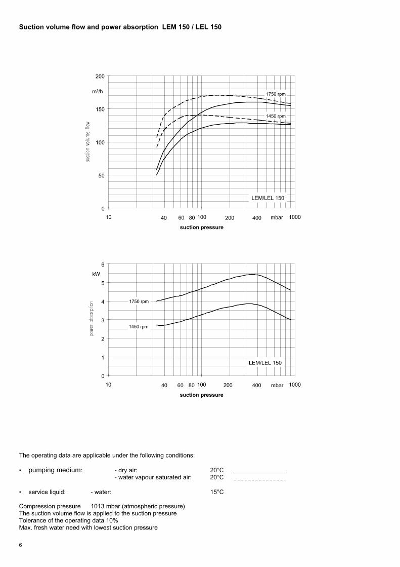
Suction volume flow and power absorption LEM 150 / LEL 150
0
50
100
150
200
10 100 1000
suction pressure
1450 rpm
1750 rpmm³/h
40 60 80 200 400 mbar
LEM/LEL 150
0
1
2
3
4
5
6
10 100 1000
suction pressure
kW
1450 rpm
1750 rpm
40 60 80 200 400 mbar
LEM/LEL 150
The operating data are applicable under the following conditions:
Compression pressure 1013 mbar (atmospheric pressure)The suction volume flow is applied to the suction pressureTolerance of the operating data 10%Max. fresh water need with lowest suction pressure
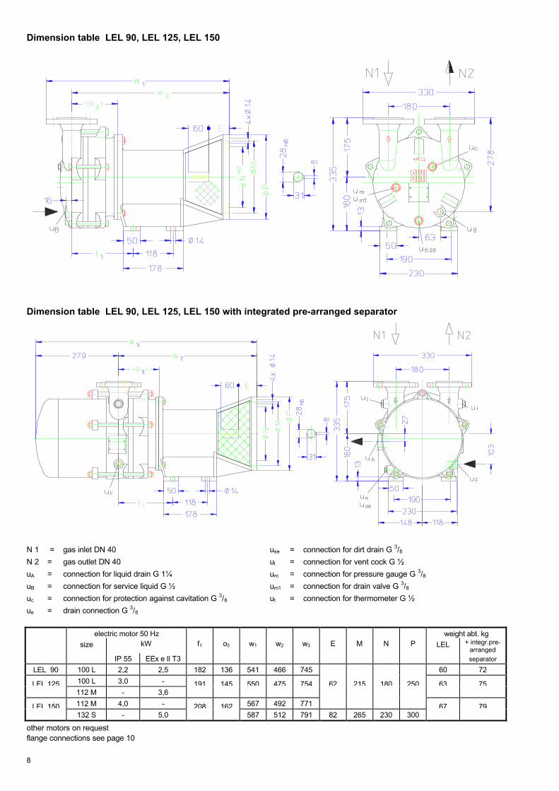
N 1 = gas inlet DN 40 use = connection for dirt drain G 3/8N 2 = gas outlet DN 40 ul = connection for vent cock G ½
uA = connection for liquid drain G 1¼ um = connection for pressure gauge G 3/8uB = connection for service liquid G ½ um1 = connection for drain valve G 3/8uc = connection for protection against cavitation G 3/8 ut = connection for thermometer G ½
ue = drain connection G 3/8
electric motor IP 55 weight abt. kg
size kW f1 f2 h1 h2 h3 h4* m m1 m2 m3 m4 m5 n n1 n2 n3 o3 w* w1* w2* LEM +integr. pre-arranged
N 1 = gas inlet DN 40 use = connection for dirt drain G 3/8N 2 = gas outlet DN 40 ul = connection for vent cock G ½
uA = connection for liquid drain G 1¼ um = connection for pressure gauge G 3/8uB = connection for service liquid G ½ um1 = connection for drain valve G 3/8uc = connection for protection against cavitation G 3/8 ut = connection for thermometer G ½
ue = drain connection G 3/8
electric motor 50 Hz weight abt. kgsize kW f1 o3 w1 w2 w3 E M N P LEL + integr.pre-
arrangedIP 55 EEx e ll T3 separator
LEL 90 100 L 2,2 2,5 182 136 541 466 745 60 72
LEL 125 100 L 3,0 - 191 145 550 475 754 62 215 180 250 63 75112 M - 3,6
other motors on requestflange connections see page 10
9
Arrangement drawing LEM 90, LEM 125, LEM 150
electric motor IP 55 weightsize kW abt. kg
50 Hz 60 Hz
LEM 90 100 L 2,2 3,3 65
LEM 125 100 L 3,0 - 72
112 M - 4,8 78
LEM 150 112 M 4,0 - 80
132 M - 6,0 105
** see list of accessoriesother motors on requestflange connections see page 10
N 1 = gas inlet DN 40N 2 = gas outlet DN 50uA = connection for liquid drain G 1uA1 = connection for liquid drain G ½uF = connection for fresh liquid G ½uc = connection for protection against cavitation G 3/8
10
Arrangement drawing LEL 90, LEL 125, LEL 150
electric motor 50 Hz weightsize kW w * w2 abt. kg
IP 55 EEx e ll T3
LEL 90 100 L 2,2 2,5 303 466 91
LEL 125 100 L 3,0 - 475 98
112 M - 3,6 320 104
LEL 150 112 M 4,0 - 492 106
132 S - 5,0 405 512 141
flange connections to DIN 2501 PN 10
DN 40 50
k 110 125
D 150 165
number x d2 4 x 18 4 x 18
* dimensions dependent on the motor make** see list of accessoriesother motors on request
N 1 = gas inlet DN 40
N 2 = gas outlet DN 50uA = connection for liquid drain G 1
uA1 = connection for liquid drain G ½
uF = connection for fresh liquid G ½
uc = connection for protection against cavitation G 3/8
11
Data regarding the pump size - order hints
series +size
hydraulics + bearings shaft sealing material design casing seal
A•R•
•Z
•B
hydraulics Awith integrated pre-arranged separatortwo grease lubricatedantifriction bearingsarranged in the motoras •Z but arrangedin the motor carrier
AAE
AA1
mechanical sealO-rings Perbunan
as AAE, butO-rings Viton
0A
4B
main parts of GG
main parts ofCr Ni Mo-cast steel
0 liquid seal
90
LEM 125 AZ, RZ
150 AAE, AA1 0A, 4B 090
LEL 125 AB, RB
150
Motor selection table for LEM
motor enclosure IP 55 50 Hz motor enclosure IP 55 60 Hz
Y-voltageV +/- 5%
∆-voltageV +/- 5%
powerkW
size motor-design.
Y-voltageV +/- 5%
∆-voltageV +/- 5%
powerkW
size motor-design.
LEM 90 346-440 200-254 2,2 100 L BW 346-480 200-277 3,3 100 L BX
LEM 125 346-440 200-254 3,0 100 L KW 346-480 200-277 4,8 112 M MX
LEM 150 660-725 380-420 4,0 112 M CX --- 380-480 6,0 132 M DX
Example for ordering:
The construction size LEM 125 AZ AAE 0A 0 with 3 kW three-phase ac motor (50 Hz, 230 V∆) 1450 rpmhas the complete order number: LEM• 125 AZ AAE 0A 0 KW
Design for LEL
designation electric motor 50 Hz
pump with free shaft end 01 motor enclosure IP 55 motor enclosure EEx e ll T3
pump with coupling, pre-drilled at motor side 04 kW size designation kW size designation
as above, but with motor, for example 2,2 100 L KB 2,5 100 L LK3,0 kW three-phase motor i.e. LB 3,0 100 L LB 3,6 112 M MK
(50 Hz, 230 V∆) at 1450 rpm 4,0 112 M MB 5,0 132 S NK
Example for ordering:
The construction size LEL 125 AB AAE 0A 0 with 3 kW three-phase ac motor (50 Hz, 230 V∆) 1450 rpmhas the complete order number: LEL• 125 AB AAE 0A 0 LB
If motors with other voltage or frequency are required a special information should be given.
On delivery the point (•) in the fourth place of the type cope is replaced by a letter in the factory.
12
Accessories LEM 90, LEM 125, LEM 150
Recommended accessoriesLEM 90LEL 90
LEM 125LEL 125
LEM 150LEL 150
Overhead liquid separator typeweight
XBa 10429,7 kg
material design 130 / galvanized172 / 1.4571
SIHI part No. 35 000 39635 000 397
service liquid line
material design 072 / St 37-0172 / 1.4571
SIHI part No. 35 003 24435 007 969
cavitation protection line
material design 072 / St 37-0172 / 1.4571
SIHI part No. 35 003 59935 003 600
Upright liquid separator typeweight
XBp 41328 kg
material design 130 / galvanized172 / 1.4571
SIHI part No. 35 000 50235 000 503
service liquid line
material design 072 / St 37-0172 / 1.4571
SIHI part No. 35 009 41835 005 534
discharge line (bend)
material design 072 / St 37-0172 / 1.4571
SIHI part No. 35 003 17235 005 535
cavitation protection line
material design 072 / St 37-0172 / 1.4571
SIHI part No. 20 041 54320 041 544
SIHI-gas ejector at service liquid temperature 15 °C GEV 90 A GEV 125 A GEV 150 A
at service liquid temperature 30 °C GEV 90 B GEV 125 B GEV 150 B
SIHI ball type non-return valve type / weight XCk 40 / 2,8 resp. 5,2 kg material design 767 / GG 25
784 / 1.4408SIHI part No. 43 016 890
43 030 996
Support foot only for series LEM for motor size 100 L, 112 M for motor size 132 M
SIHI part No. 20 047 010-
20 047 01020 047 012
Standard motor only for series LELIP 55 size
powerweight
100 L2,2 kW18 kg
100 L3,0 kW20 kg
112 M4,0 kW28 kg
EEx e ll T3 sizepowerweight
100 L2,5 kW22 kg
112 M3,6 kW30 kg
132 S5,0 kW65 kg
Coupling only for series LELfor motor IP 55 pump side motor side
type / weightSIHI part No.
B 80 / 1,5 kg43 021 41443 021 417
for motor EEx e ll T3 pump side motor side
type / weightSIHI part No.
BDS 88 / 1,9 kg43 028 11243 024 707
BDS 103 / 3,1 kg43 026 56443 025 941
Intermediate flange only for series LEL for motor flange ∅ 300 081 / 1.0038
058 /stove enamelSIHI part No. 20 043 024
20 045 646
Any changes in the interest of the technical development are reserved.
S t e r l i n g S I H I G m b HLindenstraße 170 , D-25524 Itzehoe, Germany , Telephone +49 (0) 48 21 / 7 71-01 , Fax +49 (0) 48 21 / 7 71-274