APPLICATION – CLIPLITE litepipes provide a method of transmitting the light of a surface mount LED to the display panel. Both vertical and horizontal PCB surface mount LEDs can be displayed in this manner. The litepipe is also capable of blending multicolor LED light into a single color. INTENSITY – CLIPLITE litepipes have a unique near flush design and are still able to provide up to 160 degrees of viewing angle. This light output is achieved by the use of a concave shaped receiving surface which collects the LEDs light, and fresnel rings on the opposite surface that disperse the light. VERSATILITY – CLIPLITE litepipes are available in .020" increments from .200" to 2.0". This wide range of lengths simplifies the PCB positioning in relation to the display panel. Litepipes are secured directly to the display panel with no mechanical attachment to the PCB. The installation and removal of the circuit board can thus be accomplished without disturbing the display panel. INSTALLATION – CLIPLITE litepipes are easy to install. Slide the litepipe thru the panel opening and slip the retainer in place. Finish the installation by pressing the retainer up against the display panel. VISUAL COMMUNICATIONS COMPANY, INC. 7920-F Arjons Dr., San Diego, CA 92126 In CA (858) 549-6900 (800) 522-5546 FAX (858) 549-3520 www.vcclite.com ORDERING CODES LPC XXX CTP MODEL LPC (Round) COLOR LPS (Square) CTP CLEAR LPR (Rectangular) RTN 150 (GROMMET) RTN 250 (SPRING CLIP) 020 038 056 074 092 112 135 157 180 022 040 058 076 094 115 137 160 182 024 042 060 078 096 117 140 162 185 026 044 062 080 098 120 142 165 187 028 046 064 082 100 122 145 167 190 030 048 066 084 102 125 147 170 192 032 050 068 086 105 127 150 172 195 034 052 070 088 107 130 152 175 197 036 054 072 090 110 132 155 177 200 SPECIFICATIONS MATERIAL: Litepipe - Acrylic, optical grade, (Clear). Grommet - Polyethylene, (black). Spring Clip - Spring Steel (nickel plate). MOUNTING: Panel hole: round .171" Dia.(4.34mm). square .180" X .180" (4.57 X 4.57mm). rectangular .170" X .250" (4.34 X 6.35mm). Litepipes from .200" to .500" use grommet retainer. Litepipes from .500" to 2.00" the spring clip is recommended for rigidity. LED: Surface mount, vertical and horizontal LEDs. Litepipes for blending multicolor LEDs are available on special request. U.S. & Foreign Pat. Pend. OUTLINE DRAWING MOUNTING COMPONENTS Page 2 LITEPIPE WITH HORIZONTAL SURFACE MOUNT LED LITEPIPE WITH VERTICAL SURFACE MOUNT LED LITEPIPES FOR SURFACE MOUNT LEDs Equals length in inches (Min. 020 = .200" / Max. 200 = 2.0") NOTE: Round - .200" to 2.0" Square - .300" to 2.0" Rectangular - .300" to 2.0" Nonstandard lengths available on request. Rectangular .190 X .270 Square .200 X .200 Round .190 Dia. GROMMET SPRING CLIP (4.83mm X 6.86mm) (5.08mm X 5.08mm) (4.83mm) LPR LPS LPC RTN 150 RTN 250
Transcript
A P P L I C ATION – CLIPLITE litepipes provide amethod of transmitting the light of a surface mount LED tothe display panel. Both vertical and horizontal PCB surfacemount LEDs can be displayed in this manner. The litepipe isalso capable of blending multicolor LED light into a single color.
INTENSITY – CLIPLITE litepipes have a unique nearflush design and are still able to provide up to 160 degreesof viewing angle. This light output is achieved by the useof a concave shaped receiving surface which collects theLEDs light, and fresnel rings on the opposite surface thatdisperse the light.
V E R S AT I L I T Y – CLIPLITE litepipes are available in.020" increments from .200" to 2.0". This wide range oflengths simplifies the PCB positioning in relation to thedisplay panel. Litepipes are secured directly to the displaypanel with no mechanical attachment to the PCB. Theinstallation and removal of the circuit board can thus beaccomplished without disturbing the display panel.
I N S TA L L ATION – CLIPLITE litepipes are easy toinstall. Slide the litepipe thru the panel opening and slipthe retainer in place. Finish the installation by pressing theretainer up against the display panel.
VISUAL COMMUNICATIONSCOMPANY, INC.7920-F Arjons Dr., San Diego, CA 92126In CA (858) 549-6900 (800) 522-5546FAX (858) 549-3520 www.vcclite.com
NOTE:Round - .200" to 2.0"Square - .300" to 2.0"Rectangular - .300" to 2.0"Nonstandard lengthsavailable on request.
Rectangular .190 X .270 Square .200 X .200 Round .190 Dia. GROMMET SPRING CLIP(4.83mm X 6.86mm) (5.08mm X 5.08mm) (4.83mm)
LPR LPS LPC RTN 150 RTN 250
ORDERING CODE: LENS
V E R S AT I L I T Y – CLIPLITE litepipe and lens easilyprovide a method of transmitting the light from PCBmounted LEDs to the front display panel. Both styles ofLEDs, surface mount and standard packages, can be dis-played in this manner.
BRIGHTNESS – CLIPLITE litepipe by itself has a lim-ited angle of view. However, when used with VCC’s fres-nel lens the light is dispersed over the entire lens surfaceproducing 180 degrees of viewing.
A P P L I C ATION – CLIPLITE litepipes and lenses areavailable for use with both surface mount and standardpackaged LEDs in 3mm and 5mm configurations. Becauset h e re is no physical connection between the litepipe andthe PCB mounted LED, the circuit board can be installed orremoved without disturbing the panel display.
I N S TA L L ATION – CLIPLITE litepipe and lens areeasy to install. Insert the lens thru the panel opening andsnap the litepipe into the lens. For added security in harshenvironments, a retaining ring is available.
VISUAL COMMUNICATIONSCOMPANY, INC.7920-F Arjons Dr., San Diego, CA 92126In CA (858) 549-6900 (800) 522-5546FAX (858) 549-3520 www.vcclite.com
Lens - Polycarbonate; Ring - Polypropylene(U.L. Listed Material).
DESIGN: LITEPIPE (3mm and 5mm) with annular ring andlocking tab engages into the annular groove ofVCC’s low profile lens. Lens mounts the litepipesecurely to the display panel and provides 180degrees of viewing angle.
MOUNTING: LITEPIPE 3mm - Mates with VCC’s lenses modelSMB 200 and SMQ 250. Panel mounting hole.171 (4.3mm) on 1/4" centers. Panel thickness1/32" to 1/8". Litepipe lengths from .200" to1.200".
LITEPIPE 5mm - Mates with VCC’s lens modelCLB 300 and SQB 400. Panel mounting hole.250 (6.35mm) on 3/8" centers. Panel thickness1/32" to 1/4". Litepipe lengths from .360" to1.360". For panels less than 3/16" use SPC 125spacer.
LENS RETAINING RING - available for addedsecurity (RNG 190, 3mm & RNG 268, 5mm).
STANDOFF: Use VCC’s standoff to adjust the height of astandard LED above the PCB and maintain amaximum .050" clearance between litepipe andLED. See VCC’s STD Series data sheet.
V E R S AT I L I T Y – CLIPLITE litepipe assembly pro v i d e sa method of transmitting the light from PCB mounted LEDsto the front display panel. Both styles of LEDs, surfacemount, 3mm and 5mm standard packages can be dis-played in this manner.
BRIGHTNESS – C L I P L I T E i n c reases the appare n tbrightness and viewing angle of a PCB mounted LED.Litepipe transmits the light from the source to the lens,which in turn disperses the light up to 180 degre e s .
A P P L I C AT I O N – CLIPLITE assembly meets NEMA 3conditions for moisture and dust. Because there is nophysical connection between the litepipe and PCB mount-ed LED, the circuit board can be installed or removedwithout disturbing the panel display.
I N S TA L L ATION – CLIPLITE litepipe and lens assem-bly is easily installed. Pass assembly thru panel openingand press on retaining ring to secure unit to the panel.Slide PCB into position aligning LED with the end of thelitepipe.
VISUAL COMMUNICATIONSCOMPANY, INC.7920-F Arjons Dr., San Diego, CA 92126In CA (858) 549-6900 (800) 522-5546FAX (858) 549-3520 www.vcclite.com
Litepipe - Acrylic (Clear optical grade) Lens - Polycarbonate, Seal - J-Von Ring - Polypropylene (black) (U.L. Listed Materials )
DESIGN: Low profile lens assembly with moisture seal and litepipe.
MOUNTING: Mounts in .281" (7.2mm) hole on 3/8" centers. Panel thickness 1/32" to 1/8". Compression ofthe seal is accomplished by pressing the retainingring into place.
STANDOFF: Use standoff to adjust height of standard LED above the PCB in order to maintain a maximum .050" clearance between litepipe and LED. See STD Series data sheet.
U.S.& FOREIGN PAT ISSUED & PEND.
OUTLINE DRAWINGRECOMMENDED LEDs
Page 4
PANEL ASSEMBLY
APPLICATION
MOISTURE SEALED LITEPIPE ASSEMBLY
LMS Litepipe/Lens Assembly RNG 268
Pass lens thru panel opening. Press on retaining ring. Air gap .050"max. between LED and litepipe. Use standoff to adjust LED height.
Hold lens tightly to panel, careful not to mar lens surface. Use 5/16"nut driver or deep socket to press on retaining ring, compressing seal.
RTP Red TransparentATP Amber TransparentGTP Green TransparentBTP Blue TransparentYTP Yellow TransparentCTP Clear Transparent
V I S I B I L I T Y – CLIPLITE produces up to 180 degrees ofviewing angle using standard 3mm and 5mm LEDs.
BRIGHTNESS – CLIPLITE utilizes striated lines andf resnel rings to increase apparent brightness up to 125%and viewing angle up to 180 degrees with either diffused orn o n d i ffused LEDs. A low profile lens without rings or lines isavailable for direct sunlight applications.
PROTECTION – CLIPLITE helps prevent IC failure scaused by electrostatic discharge (ESD). Simply walkinga c ross a carpet can generate 10,000 volts. Introduction ofthis ESD thru an exposed panel mounted LED is capable ofdamaging or destroying a semiconductor. A CLIPLITEmounted LED helps guard components from ESD up to 16kv while aff o rding the LED physical pro t e c t i o n .
I N S TA L L ATION – CLIPLITE, standard or low pro f i l e ,re q u i res no assembly tools; just snap into a panel openingand insert LED. Cost effective operation is complete in only6 seconds.
VISUAL COMMUNICATIONSCOMPANY, INC.7920-F Arjons Dr., San Diego, CA 92126In CA (858) 549-6900 (800) 522-5546FAX (858) 549-3520 www.vcclite.com
DESIGN: Standard and low profile lenses with fresnel ringsand striated lines. CLR 301 Low Profile Lens isavailable without fresnel rings.
MOUNTING: Mounts thru front of panel. Mounting holes shouldbe deburred but not chamfered.3mm (SML 190, SMB 200) mounts in a .171 ±.002 (4.34mm) hole on 1/4" centers. Panel thick-ness for SML 190, 1/32" to 1/16"; SMB 200,1/16" to 1/8". 5mm (CLF 280, CLB 300, CLR 301)mounts in a .250 ± .002 (6.35mm) hole on 3/8"centers. Panel thickness for CLF 280, 1/16" to1/8"; CLB 300 and CLR 301, 1/32" to 1/4"; forpanels less than 3/16", use SPC 125 spacer.Lens retaining ring - available for added security(RNG 190, 3mm & RNG 268, 5mm)
While holding the CLIPLITE tight to the panel with yourfinger, insert the LED into the CLIPLITE from the back.
V I S I B I L I T Y – CUBELITE standard square lens off e r s20% more viewing area over a round indicator light. CUBE-LITE’S unique patented features include striated lines andf resnel rings permitting up to 180 degrees viewing angle withany stock 3mm or 5mm LED.
D E S I G N – CUBELITE standard lens mounts in a squarehole. Its uniform lens thickness produces an even light pat-t e rn with no dark corners. CUBELITE low profile square lensmounts in a round hole. This lens has a .070 inch max panelheight and still produces 180 degree viewing angle. CUBE-LITE’S design permits use of either diffused or nondiff u s e dL E D s .
P R O T E C T I O N – CUBELITE helps prevent IC failure scaused by electrostatic discharge (ESD). Simply walkinga c ross a carpet can generate 10,000 volts. Introduction ofthis ESD thru an exposed panel mounted LED is capable ofdamaging or destroying a semiconductor. A CUBELITEmounted LED helps guard components from ESD up to16,000 volts as well as aff o rding the LED physical pro t e c t i o n .
I N S TA L L AT I O N – CUBELITE, standard or low pro f i l e ,re q u i res no assembly tools; just snap into a panel openingand insert LED. Cost effective operation is complete in only6 seconds.
VISUAL COMMUNICATIONSCOMPANY, INC.7920-F Arjons Dr., San Diego, CA 92126In CA (858) 549-6900 (800) 522-5546FAX (858) 549-3520 www.vcclite.com
SQUARE LENS/MOUNTS FOR 3mm & 5mm LEDs
SPECIFICATIONS
M AT E R I A L : LENS - Polycarbonate; Spacer - Polypropylene (U.L. Listed).
M O U N T I N G : Mounts thru front of panel. Mounting holes shouldbe deburred but not chamfere d .3mm (SMQ 250) mounts in .171 ± .002 (4.34mm)round hole on 1/4" centers. Panel thickness fro m1/16" to 1/8".5mm (SQL 360) mounts in .250 ± .002 (6.35mm)s q u a re punched hole on 3/8" centers. Panel thickness from 1/16" to 1/8".5mm (SQB 400) mounts in .250 ± .002 (6.35mm)round hole on 3/8" centers. Panel thickness fro m1/32" to 1/4"; for panels less than 3/16", use SPC125 spacer.S t a n d a rd metal or plastic washers can also beused to increase panel thickness if necessary.PUNCH SOURCES: Porter Precision, Cincinnati, OH Strippet, Houdaille Ind., A k ron, NY Unipunch Products, Buffalo, NYWiederman Co., King of Prussia, PA .
U.S. & Foreign Pat. Pend.
OUTLINE DRAWINGS
Page 6
SQL 360 RTP
M O D E L C O L O RRTP Red TransparentATP Amber TransparentGTP Green TransparentBTP Blue TransparentYTP Yellow TransparentCTP Clear Transparent
While holding the CUBELITE tight to the panel with your finger,insert the LED into the CUBELITE from the back.
Snap CUBELITE in a 1/4" panel hole.
SMQ 250 (3 m m ) SQB 400 (5 m m ) SQL 360 (5 m m )
RECOMMENDED LEDs
EASY TWO-STEP INSTALLATION
2.
1.
3 m m 5 m m
RECOMMENDED LEDs
V E R S AT I L I T Y – CLIPLITE, installed in display panel,is used with PCB mounted LEDS. Lenses remain attachedto the display or panel door while the LEDs are fixed to thePCB. The lenses are ideal for use together with theCONXRITE connector assembly.
BRIGHTNESS – CLIPLITE utilizes fresnel rings toi n c rease apparent brightness and viewing angle up to 180d e g rees with either diffused or nondiffused LEDs.
PROTECTION – CLIPLITE helps prevent IC failure scaused by electrostatic discharge (ESD). Introduction ofESD thru an exposed panel mounted LED is capable ofdamaging or destroying a semiconductor. A CLIPLITEmounted LED helps guard components from ESD up to 16kv while aff o rding the LED physical pro t e c t i o n .
I N S TA L L ATION – CLIPLITE is inserted thru panelopening, retaining ring pressed into place. PCB mountedLEDs slide into lenses when the panel cover is closed or thePCB card is inserted into the case.
VISUAL COMMUNICATIONSCOMPANY, INC.7920-F Arjons Dr., San Diego, CA 92126In CA (858) 549-6900 (800) 522-5546FAX (858) 549-3520 www.vcclite.com
LOW PROFILE PANEL LENSES FOR PCB MOUNTED LEDs
ORDERING CODES
SPECIFICATIONSMATERIAL: Lens - Polycarbonate; Ring - Polypropylene ,
MOUNTING: Mounts thru front of panel, retaining ring securesthe lens in place. 5mm CMC & CML seriesmount in a .281"(7.2mm) hole on 3/8" centers,Panel thickness 1/32 to 1/4".
3mm (SMC 170) mounts in a .171" (4.4mm) holeon 1/4" centers. Panel thickness 1/32" to 3/32".
5mm CMC & CML series mount in a .281" ( 7 . 2 m m )hole on 3/8" centers. Panel thickness 1/32" to 1 / 4 " .
Install lens thru panel, secure with retaining ring. The PCB mountedLED then slides into lens.
Install lens thru panel, insert LED into connector, press connector onto lens to complete installation.
U.S. & Foreign Pat. Pend.
Page 7
PANEL MOUNTED LENS WITH CONXRITE CONNECTOR
PANEL MOUNTED LENS WITH PCB MOUNTED LED
CMC 321 RTPMODEL COLOR
SMC 170 (3mm) Fresnel L/Profile Lens RTP Red TransparentCMC 313 (5mm) Plain Diffused Lens ATP Amber TransparentCMC 321 (5mm) Fresnel L/Profile Lens GTP Green TransparentCMC 323 (5mm) Plain End Lens YTP Yellow TransparentCML 325 (5mm) Fresnel L/Profile Lens BTP Blue TransparentCML 327 (5mm) Plain End Lens CTP Clear TransparentRNG 132 (3mm) Retaining Ring *Denotes Clear onlyRNG 268 (5mm) Retaining Ring
V E R S AT I L I T Y – CLIPLITE, installed in display panel,provides a moisture seal effective against splash and dripconditions. The lens can be used with either circuit boardmounted or panel mounted LEDs. For PCB mountingapplications the lens remains attached to the display orpanel door while the LEDs are fixed to the PCB. The lensis ideal when used with the CONXRITE connector formounting the LED directly to the display panel.
BRIGHTNESS – CLIPLITE utilizes fresnel rings toincrease apparent brightness and viewing angle up to 180degrees with either diffused or nondiffused LEDs.
PROTECTION – CLIPLITE tests show it is an effec-tive moisture seal in splash and drip conditions. In addi-tion, the lens helps prevent IC failures caused by electro-static discharge (ESD). A CLIPLITE mounted LED guardscomponents from ESD up to 16 kV while affording the LEDphysical protection.
I N S TA L L ATION – CLIPLITE is inserted thru panelopening, retaining ring is then pressed into place com-pressing the seal. PCB mounted LEDs slide easily intolens allowing simple insertion or removal of the PCB.Panel mounting of the LED is accomplished with theCONXRITE connector which also serves to compress themoisture sealing ring.
VISUAL COMMUNICATIONSCOMPANY, INC.7920-F Arjons Dr., San Diego, CA 92126In CA (858) 549-6900 (800) 522-5546FAX (858) 549-3520 www.vcclite.com
TESTING: Environmental testing performed byConsolidated Labs, Inc. for moisture sealing,shock, vibration and standard operating temper-atures. Meets Nema 3 standards.
MOUNTING: Mounts thru front of panel, compression of theseal is accomplished by pressing the retainingring or CONXRITE connector in place.
5mm (CMS 322), mounts in a 9/32" (7.2mm) holeon 3/8" centers. Panel thickness 1/32" to 1/8".Hole should be deburred but not chamfered.
See specs. page 11 for use with CNX connectors.
Install lens thru panel, press ring onto lens to compress seal. PCBmounted LED slides into lens.
Install lens thru panel, insert LED into connector, press connector onto lens to compress seal.
U.S. & Foreign Pat. Pend.
Page 8
PANEL MOUNTED LENS WITH CONXRITE CONNECTOR
PANEL MOUNTED LENS WITH PCB MOUNTED LED
CMS 322 RTPMODEL COLOR
CMS 322 (5mm) L/Profile Lens RTP Red Transparentwith moisture seal ATP Amber Transparent
RNG 268 (5mm) Retaining Ring GTP Green TransparentBTP Blue TransparentYTP Yellow TransparentCTP Clear Transparent
CMS 322 (5mm) RNG 268 (5mm)
OUTLINE DRAWING5mm
RECOMMENDED LEDs
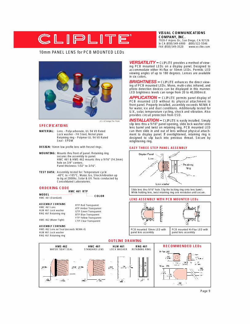
V E R S AT I L I T Y – C L I P L I T E p rovides a method of view-ing PCB mounted LEDs on a display panel. Designed toaccommodate either Hi-flux or 10mm LEDs. Permits LEDviewing angles of up to 180 degrees. Lenses are availablein six colors.
BRIGHTNESS – C L I P L I T E enhances the direct view-ing of PCB mounted LEDs. Mono, multi-color, infrared, andphoto detection devices can be displayed in this manner.LED brightness levels can range from 20 to 40,000mcd.
A P P L I C AT I O N – CLIPLITE permits panel display ofPCB mounted LED without its physical attachment tofront panel. Properly installed, assembly exceeds NEMA 4for water, ice and dust conditions. Additionally tested forU.V., solar, temperature cycling, shock and vibration. Alsoprovides circuit protection from ESD.
I N S TA L L ATION – C L I P L I T E is easily installed. Simplyslip lens thru a 9/16" panel opening, slide lock washer ontolens barrel and twist on retaining ring. PCB mounted LEDcan then slide in and out of lens without physical attach-ment to display panel. If overtightened, retaining ring isdesigned to slip back into previous thread. Secure byretightening ring.
VISUAL COMMUNICATIONSCOMPANY, INC.7920-F Arjons Dr., San Diego, CA 92126In CA (858) 549-6900 (800) 522-5546FAX (858) 549-3520 www.vcclite.com
ORDERING CODEHMC 461 RTP
MODELHMC 461 (Standard)
ASSEMBLY CONTAINSHMC 461 LensHLW 461 Lock washerRNG 461 Retaining ring
HMS 462 (Water Tight)
ASSEMBLY CONTAINSHMS 462 Lens w/ Seal (exceeds NEMA 4)HLW 461 Lock washerRNG 461 Retaining ring
SPECIFICATIONSMATERIAL: Lens - Polycarbonate, UL 94 V0 Rated
Lock washer - FH Steel, Nickel plateRetaining ring - Polymer UL 94 V0 RatedSeal - EPDM
DESIGN: 16mm low profile lens with fresnel rings.
MOUNTING: Mounts thru front of panel. Retaining ringsecures the assembly to panel.HMC 461 & HMS 462 mounts thru a 9/16" (14.3mm)hole on 3/4" centers.Panel thickness 1/32" to 3/16".
TEST DATA: Assembly tested for: Temperature cycle-40°C to +105°C, Water, Ice, Shock/vibration upto 6g at 2000hz, Solar & UV. Tests conducted byConsolidated Laboratories.
U.S. & Foreign Pat. Pend.
OUTLINE DRAWINGRECOMMENDED LEDs
Page 9
LENS ASSEMBLY WITH PCB MOUNTED LEDs
EASY THREE STEP PANEL ASSEMBLY
10mm PANEL LENS for PCB MOUNTED LEDs
HMC 461STANDARD LENS
HLW 461LOCK WASHER
RNG 461RETAINING RING
Slide lens thru 9/16" hole. Slip the locking ring onto lens barre l .While holding lens, twist retaining ring one revolution until secure .
PCB mounted Hi-Flux LED withpanel lens assembly
PCB mounted 10mm LED withpanel lens assembly
RTP Red TransparentATP Amber TransparentGTP Green TransparentBTP Blue TransparentYTP Yellow TransparentCTP Clear Transparent
COLOR
HMS 462WATER TIGHT SEAL
C O N X R I T E – T h i s modular cabling assembly isdesigned for use in the electrical connection of panelmounted LEDs to printed circuit boards. This plug-in sys-tem eliminates many of the problems associated withwiring display panel mounted LEDs.
A P P L I C AT I O N S – Designed to make quick and easyplug-in connections between panel mounted LEDs and thePCB. The modular concept of panel and header housingsalong with diff e rent wire lengths offer a cost reducing solu-tion to cabling pro b l e m s .
V E R S AT I L I T Y – Multiple panel mounted LEDdevices can be connected to PCB mounted headers. Auniquely designed three finger box terminal mates withleads .017" in diameter to .025" square. Cables are avail-able in four, six, eight, twelve, eighteen and twenty fourinch lengths.
INSTALLATION – Modular cabling systems simplifythe electrical connection from panel to PCB and eliminatethe need for assembly tools. Cost savings from the dis-continuing of soldering and terminal crimping operationsare substantial. When properly installed the assembly isable to withstand up to 6g’s at 2000hz.
VISUAL COMMUNICATIONSCOMPANY, INC.7920-F Arjons Dr., San Diego, CA 92126In CA (858) 549-6900 (800) 522-5546FAX (858) 549-3520 www.vcclite.com
PRE-WIRED SOLDERLESS LED INTERCONNECT
SPECIFICATIONS
M AT E R I A L : Panel Connector Socket & Ring - Thermoplastic.Header Connector - Thermoplastic (UL listedmaterials) Terminals - Phosphor bronze, tin plated.W i re - 22 AWG, 7 strand copper, insulated.
E L E C T R I C A L : Terminal - 3 amp continuous service.Unique three-finger design mates to round, squareor rectangular leads .017" to .025".
M O U N T I N G : Panel Connector 3mm - Mates with SMC 130 &1 7 0.Panel Connector 5mm - Mates with CMC 285,313, 321, 323, CMS 322, CML 325 and 327. Seedata sheets pages 4, 5 & 6.Panel Thickness: - See page 11All holes deburred but not chamfere d .
LED lead trimming - See page 11.
Hole Size - SMC series11/64" (4.37mm).CMC, CMS & CML series 9/32"( 7 . 1 4 m m ) .
Header Connector - Mates with VCC positivelocking header 450 series. Also mates with stan-d a rd and friction header .025" pins on .100" cen-t e r s .
Insert LED into connector. Install lens in panel opening. Pressconnector and lens together.
Insert LED into socket. Press socket into panel and securewith ring.
U.S. & Foreign Pat. Pend.
RECOMMENDED LEDs
Page 10
PANEL SOCKET, FRONT RELAMPABLE
PANEL MOUNT LENS & CONNECTOR
3mm Bi-Lead 5mm Bi-Lead 5mm Tri-Lead 5mm FlangelessUse “B” Connector Use “C” Connector Use “D” Connector Use “K” Connector
Page 11
VISUAL COMMUNICATIONSCOMPANY, INC.7920-F Arjons Dr., San Diego, CA 92126In CA (858) 549-6900 (800) 522-5546FAX (858) 549-3520 www.vcclite.com
PANEL (LED) SIDE P C BOARD SIDE STANDARD 1 - WHT - BLK 04 4 INCHES24 AWG 2 - RED - BLK 06 6 INCHES
B 3mm Panel Connector 2 Lead E Locking Hdr Connector 2 Lead 6 - WHT - RED - BLK 08 8 INCHESC 5mm Panel Connector 2 Lead F Locking Hdr Connector 3 Lead OPTIONAL 10 10 INCHESD 5mm Panel Connector 3 Lead G Plain Hdr Connector 3 Lead 22 AWG 12 12 INCHESK Panel Socket 2 Lead 18 18 INCHES
X Wire Leads - Stripped Ends 24 24 INCHES
SEE PAGE 14 FOR AVAILABLE RESISTOR VA L U E S
LED lead length: CMC 285 = .320" ±.01 * CMC 313, CMC 321, CMC 323,CMS 322 = .220"±.01
Panel thickness: .030" - .045" use 2ea. SPC 060 spacers, .050" - .100" use1ea. SPC 060 spacer, .105" - .125" SPC 060 not re q u i re d
LED lead length: CMC 285 = .350" ±.01 CML 325, CML 327 = .275"±.01
Panel thickness: CMC 285, 030" - .045" 2ea. SPC 060, .050" - .100" 1ea.SPC 060, 105" - .125" SPC not re q u i re d .CML 325, 327 - .060" - .100" use 2ea. SPC 060 spacers,. 1 0 5"- .175" 1ea. SPC 060, .150" - .220" SPC not re q u i re d .
450 220 5mm Bi-LEAD (“C” CONNECTOR)
LED lead length: 5mm flangeless LED .250"Panel thickness: .030" - .250"
Use RNG 242 retaining ring when additional security isrequired.
P/N DESCRIPTIONG CONNECTOR 2 POSITION PLAIN HEADERE CONNECTOR 2 POSITION LOCKING HEADERF CONNECTOR 3 POSITION LOCKING HEADERNote: For additional header connector specifications refer to page 18.
LED lead length: SMC 130 = .380" * SMC 170 = .320"Panel thickness: .030" - .050" use 1ea. SPC 040 spacer
CMS 322 = .250"±.01Panel thickness: .030" - .045" use 2ea. SPC 060 spacers, .050" - .100" u s e
1ea. SPC 060 spacer, .105" - .125" SPC 060 not re q u i re d
CALL FACTORY FOR ADDITIONAL OPTIONS
VERSATILITY – CONXRITE cabling system simpli-fies display panel to power source interface. Optionsinclude: LED - 5mm, 10mm Hi-Flux. Color - mono, bi-color, tri-color, RGB. Wire - size, color, length. Wire termi-nation - header / connector, positive locking, single, dualrow. Terminals - ring or spade style.B R I G H T N E S S – CONXRITE enhances LED apparentbrightness as well as the viewing angle to 180°. Visible,infrared, and photo detection devices can be displayed inthis manner. Illumination can range from 20 to 20,000mcd.A P P L I C AT I O N – CONXRITE LED cable assembliesare used in consumer products, communications, indus-trial, automotive, heavy equipment, security systems, inte-rior and exterior projects. Tested for temperature cycling,UV, solar, shock, vibration. Sealed version exceeds NEMA4 for dust, water and ice. Also provides ESD circuit protection.INSTALLATION – CONXRITE assemblies “plug andplay” approach simplifies cable installation. Slip lens thrupanel opening, slide lock washer over lens barrel, connec-tor secures to lens with a half turn.
VISUAL COMMUNICATIONSCOMPANY, INC.7920-F Arjons Dr., San Diego, CA 92126In CA (858) 549-6900 (800) 522-5546FAX (858) 549-3520 www.vcclite.com
CABLE ASSEMBLIES FOR 5mm & 10mm LED LIGHTS
SPECIFICATIONSM AT E R I A L : Lens - Polycarbonate, UL 94 V0
Connector - Polymer (white), UL 94 V0M o i s t u re seal - EPDMLock washer - Steel, nickel plateTerminals - Phosphor bronze, tin plateW i re - U.L.1007/1569, 22-24 awg stranded
E L E C T R I C A L : Terminal - 3 amp continuous service. Mates withround, square, rectangular leads .017" to .030"
M O U N T I N G : CMC / HMC series lens for standard dry applications.CMS / HMS series lens for dust and wet conditions.CMC 441 / CMS 442 lens mount thru a 5/16" (8mm)opening on 1/2" centers. Panel thickness 1/32" to 1/8".HMC 461 and HMS 462 lens mount thru 9/16" (14mm)opening on 3/4" centers. Panel thickness 1 / 3 2 " to 3/16".
W i re termination - VCC 450 series single or dual ro wpositive locking header connectors, stripped leads.Contact factory for other termination options.
TEST DATA : Assembly tested for Shock /v i b r a t i o n - 6 g ’s at 2000hz,Te m p e r a t u re - 40° to + 105°C, Solar and UV. MeetsNEMA 4, for water, ice and dust. Test conducted byConsolidated Laboratories Inc.
L E D s : 5mm LEDs bi-lead, trim leads to .250" ±.010 (6.35mm)10mm LEDs bi-lead, trim leads to .300"± .010 (7.62mm)Hi-flux LEDs 4 leads trimming not re q u i red.
Contact factory for additional wire and LED options.Tri-lead and six lead devices.
U.S. & Foreign Pat. Pend.
LENS AND CONNECTOR ASSEMBLIES
EASY THREE STEP PANEL ASSEMBLY
Slide lens thru panel opening. Slip the lock washer onto lens barre l .While holding lens, twist on connector one half turn until secure .
OUTLINE DRAWING
RECOMMENDED LEDs
Page 12
CNX 440CONNECTOR ASSEMBLY
Connector assembly with sealedlens for water tight applications.
Connector assembly with stan-dard lens for dry applications.
CMC 441 / CMS 442LENS
HLW 461LOCK WASHER
CNX 460CONNECTOR ASSEMBLY
HMC 461 / HMS 462LENS
CLW 441LOCK WASHER
Page 13
VISUAL COMMUNICATIONSCOMPANY, INC.7920-F Arjons Dr., San Diego, CA 92126In CA (858) 549-6900 (800) 522-5546FAX (858) 549-3520 www.vcclite.com
CABLE ASSEMBLY FOR 5mm & 10mm LED LIGHTS
CABLE ASSEMBLY FOR 10mm AND HI-FLUX LED LIGHTS
CNX 440 STANDARD ASSEMBLIES
CNX 460 STANDARD ASSEMBLIES
DRAWINGS NOT TO SCALE
LED 5mm bi-lead - trim lead length .250" ±.01 (5.58mm)Panel Thickness - .032" to .125", Panel Hole: .312" (8.0mm)
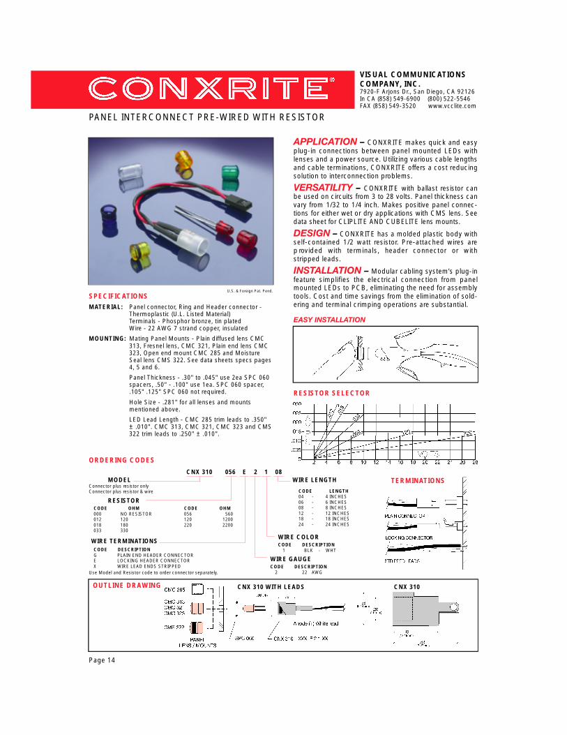
APPLICATION – CONXRITE makes quick and easyplug-in connections between panel mounted LEDs withlenses and a power source. Utilizing various cable lengthsand cable terminations, CONXRITE offers a cost reducingsolution to interconnection problems.
V E R S AT I L I T Y – CONXRITE with ballast resistor canbe used on circuits from 3 to 28 volts. Panel thickness canvary from 1/32 to 1/4 inch. Makes positive panel connec-tions for either wet or dry applications with CMS lens. S e edata sheet for CLIPLITE AND CUBELITE lens mounts.
DESIGN – CONXRITE has a molded plastic body withself-contained 1/2 watt resistor. Pre-attached wires arep rovided with terminals, header connector or withstripped leads.
INSTALLATION – Modular cabling system’s plug-infeature simplifies the electrical connection from panelmounted LEDs to PCB, eliminating the need for assemblytools. Cost and time savings from the elimination of sold-ering and terminal crimping operations are substantial.
VISUAL COMMUNICATIONSCOMPANY, INC.7920-F Arjons Dr., San Diego, CA 92126In CA (858) 549-6900 (800) 522-5546FAX (858) 549-3520 www.vcclite.com
PANEL INTERCONNECT PRE-WIRED WITH RESISTOR
CNX 310 056 E 2 1 08MODEL WIRE LENGTH
Connector plus resistor onlyConnector plus resistor & wire
MOUNTING: Mating Panel Mounts - Plain diffused lens CMC313, Fresnel lens, CMC 321, Plain end lens CMC323, Open end mount CMC 285 and MoistureSeal lens CMS 322. See data sheets specs pages4, 5 and 6.
Panel Thickness - .30" to .045" use 2ea SPC 060spacers, .50" - .100" use 1ea. SPC 060 spacer,.105" .125" SPC 060 not required.
Hole Size - .281" for all lenses and mounts mentioned above.
LED Lead Length - CMC 285 trim leads to .350"± .010". CMC 313, CMC 321, CMC 323 and CMS322 trim leads to .250" ± .010".
VERSATILITY – CONXRITE with internal resistormakes LED plug-in connections between panel andpower source easy. Options include broad selection ofLEDs, choices of wire size, length and color, variety of wireterminations.BRIGHTNESS – CONXRITE enhances LED viewing,180°. Also for use with infrared and photo detectiondevices. With selected LEDs, brightness can range from20 to 20,000mcd.APPLICATION – CONXRITE assembly has beentested for UV, solar, shock, vibration and temperaturecycling. Sealed version exceeds NEMA 4 for dust, waterand ice. Assembly uses include office environments orharsh exterior conditions. Provides ESD circuit protection.INSTALLATION – CONXRITE is easy to install. Sliplens thru panel opening, slide lock washer over lens bar-rel, secure connector to lens by hand with a half turn.
VISUAL COMMUNICATIONSCOMPANY, INC.7920-F Arjons Dr., San Diego, CA 92126In CA (858) 549-6900 (800) 522-5546FAX (858) 549-3520 www.vcclite.com
5mm LED PANEL INTERCONNECT w/re s i s t o r
SPECIFICATIONSM AT E R I A L : Lens - Polycarbonate, UL 94 V0
Connector - Polymer, UL 94 V0M o i s t u re seal - EPDMLock washer - Steel, nickel plateTerminals - Phosphor bronze, tin plateW i re - U.L. 1007/1569, 22, 24 awg stranded
E L E C T R I C A L : Terminal - 3 amp continuous service. Mates toround, square, rectangular leads .017" to .030"
M O U N T I N G : CMC 441 series lens - for dry applicationsCMS 442 series lens - for dust / wet conditionsCMC 441 / CMS 442 lens - mounts thru a 5/16"diameter panel opening on 1/2" centers. Panelthickness up to 1/8".W i re termination - stripped leads, VCC 450 seriessingle or dual row locking header connectors.Contact factory for other termination options.
TEST DATA : Assembly meets NEMA 4 for water, ice and dust.Additional tests, temperature cycle -40° to +85°C,shock to 6g's, vibration to 2000hz, solar & UV.Tests conducted by Consolidated Laboratories.
U.S. & Foreign Pat. Pend.
Page 15
EASY INSTALLATION
RESISTOR SELECTOR
Slide lens thru 5/16" hole. Slip the lock washer onto lens barre l .While holding lens, twist on connector one half turn until secure .
OUTLINE DRAWING
ORDERING CODECNX 441 RTP 056 E02 2 1 12
LENS STYLE COLOR RESISTOR TERMINATION WIRE SIZE WIRE COLOR WIRE LENGTH
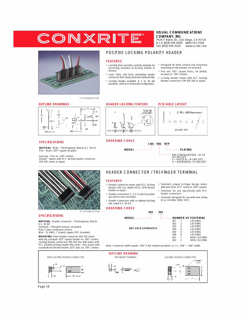
MOUNTING: Plain header connector 450 320 mateswith any standard .025" square header on .100" centers.Locking header connectors 450 302 thru 308 mates withVCC positive locking header 450 series. Also mates withs t a n d a rd and friction header .025" pins on .100" centers.
FEATURES• Locking lever provides polarity integrity by
restricting insertion of locking header inreverse.
• Lever clicks and locks preventing headerconnector from being retracted inadvertently.
• Locking header available in 2 to 28 pin positions, vertical or horizontal configuration.
• Designed for both vertical and horizontalmounting on the printed circuit board.
• Pins are .025" square brass, tin plated,located on .100" centers.
• Locking header mates with VCC lockingheader connectors P/N 450 30X or equal.
U.S. & Foreign Pat. Pend.
HEADER CONNECTOR / TRI-FINGER TERMINAL
FEATURES• Header connector mates with VCC locking
header CNX xxx, Molex 6373, 7478 frictionheader or equal.
VISUAL COMMUNICATIONSCOMPANY, INC.7920-F Arjons Dr., San Diego, CA 92126In CA (858) 549-6900 (800) 522-5546FAX (858) 549-3520 www.vcclite.com
OUTLINE DRAWING
DUAL ROW “SLIM LINE” POSITIVE LOCKING HEADER
S P E C I F I C AT I O N SMATERIAL Body - Thermoplastic (black) U. L. 94 V0Lever - thermoplastic Nylon 6-6 for flexibility U.L. 94 V2Pins - Brass .025" square, bright tin plateSpacing - Dual row, 4 to 16 circuits on .100 X .100centersHeader - Mates with VCC, 450 4xx series, female lock-ing connector.
S P E C I F I C AT I O N S
MATERIAL Connector - Thermoplastic (black) U.L. 94 V04 to16 circuits, dual ro w, with locking and polarizing latchesTerminals - Phosphor bronze, bright tin plated3 amp continuous service ratingW i re - 22 AWG, 7 strand copper, PVC insulated. 300V 105°CCall factory for additional options.Mates with VCC CNX DRT VXX positive locking dual rowpin header (.025 sq pins on .100 centers)
FEATURES• “Click it’s locked” p revents inadvertent
retraction of the connector.
• Lever detent prevents reverse insertion ofthe connector for polarity integrity.
• Vertical locking headers are available infour to sixteen pin circuits.
• Header contact pins are .025" square on.100" x .100" centers.
• Locking header mates with VCC headerconnector 450 xxx Series.
• Standoff ribs provide a .010" board clear-ance for easy flux cleansing.
U.S. & Foreign Pat. Pend.
DUAL ROW “SLIM LINE” FEMALE LOCKING CONNECTOR
FEATURES• Designed with a positive locking
mechanism. “Click it’s Locked”.
• Polarization is preserved by means of connector latches.
• Available from four to sixteen circuit configurations.
• Terminals are tested for 3 amp continuousservice.
• Available with 22 or 24 AWG stranded wirerated at 300V 105˚C rating.
• Thermoplastic materials U.L. rated at 94 V0.
U.S. & Foreign Pat. Pend.
LOCKING FEAT U R E
P C BOARD LAY O U T
POLARITY FEAT U R EOUTLINE DRAW I N G
CONNECTOR BODY
ORDERING CODES 450 404
MODEL NUMBER OF CIRCUITSSLIM LINE CONNECTOR 404 = 4 CIRCUITS
Dim. A. Circuits Dim. A. Circuits.100" 2 X 2 .500" 2 X 6.200" 2 X 3 .600" 2 X 7.300" 2 X 4 .700" 2 X 8.400" 2 X 5
P/N Dim. A. Circuits P /N Dim. A Circuits450 404 .245" 2 X 2 450 412 .625" 2 X 6450 406 .325" 2 X 3 450 414 .725" 2 X 7450 408 .425" 2 X 4 450 416 .825" 2 X 8450 410 .525" 2 X 5
Page 19
NOT SOLD SEPARATELY
VISUAL COMMUNICATIONSCOMPANY, INC.7920-F Arjons Dr., San Diego, CA 92126In CA (858) 549-6900 (800) 522-5546FAX (858) 549-3520 www.vcclite.com
LED SOCKETS FOR CIRCUIT BOARD MOUNTING
U.S. & Foreign Pat. Pend.
OUTLINE DRAWING
SPECIFICATIONSMATERIAL: Housing - Thermoplastic, (black), UL 94 V0
Contacts - Phosphor bronze, 60/40 tin plated.
MOUNTING: PCH Series - Thru-hole horizontal mounting sockets, .035"(.89mm) holes on .100" centers.PCV Series - Thru-hole vertical mounting sockets, .035"(.89mm) holes on .100" centers.SMD Series - Surface mount, horizontal mount-ing sockets, .060" (1.52mm) X .060" (1.52mm)component pad. SMD sockets available in bulk and in tubes.
LED DATA: Standard 3mm and 5mm devices Leads - Min. .017 (.43mm) round or square.
ORDERING CODES:
PCH 330
M O D E L
VERSATILITY – P-C-LITEs are soldered directly tothe PCB which permits easy insertion or removal of theLED. PCH and SMD series mount horizontally, PCV seriesmounts vertically. STD series standoff can be used tomake fine adjustments in the extended length of the LED.
DESIGN – P-C-LITEs are manufactured from UL listedthermoplastics. Unique three finger contact design per-mits automatic adjustment to the various sizes andshapes of LED leads.
A P P L I C AT I O N – P-C-LITEs are relampable socketsfor circuit board mounting of LEDs. They are used to dis-play circuit condition for status, logic and fault detection.The sockets are also used for mounting photodetectiontype devices as well as incandescent bi-pin lamps.
INSTALLATION – P-C-LITE sockets (PCH/PCV) areaffixed to PCB by wave soldering. IR reflow is used for theSMD. Molded standoffs permit easy board cleaning. LEDleads can be bent after insertion for added security.
PCH HOLE PATTERN
PCH 330HORIZONTALTHRU HOLE
PCV 220VERTICAL
THRU HOLE
SMD 330HORIZONTAL
SURFACE MOUNTPCH HOLE PATTERN
Page 20
HORIZONTAL MOUNT PCH & SMD SERIES
Insert LED - trim LED or bend LED leads for security
VERTICAL MOUNT PCV SERIES
H o r i z o n t a lM o u n t
H o r i z o n t a lM o u n t
For specifications and dimensional information visit www. v c c l i t e . c o m
d u a ls o c k e t s
t r i p l es o c k e t s
PCH 330 Horizontal Mount (Single Unit)* PCH 660 Horizontal Mount (Dual Unit)* PCH 990 Horizontal Mount (Triple Unit)
PCV 220 Vertical Mount (Single Unit)* PCV 440 Vertical Mount (Dual Unit)* PCH 880 Vertical Mount(Triple Unit)
SMD 330 Horizontal Surface Mount (Single Unit)* SMD 660 Horizontal Surface Mount (Dual Unit)* SMD 990 Horizontal Surface Mount (Triple Unit)
* View outline drawings on the webdirect url address www.vcclite.com/pch_pcv
SMD PAD PATTERN
VISUAL COMMUNICATIONSCOMPANY, INC.7920-F Arjons Dr., San Diego, CA 92126In CA (858) 549-6900 (800) 522-5546FAX (858) 549-3520 www.vcclite.com
DESIGN: Channels provide lead separation and lateral sta-bility for components. Molded tabs retain compo-nent leads within the standoff for preassembly.Raised pads allow for easy PCB cleaning.
MOUNTING: Suitable for passive components, bi-lead, tri-lead,3mm, 5mm, LEDs, resistors, capacitors, diodes.Standoffs vary in height from .100 minimum to 1.0inch maximum, increments of .010 inch.
ORDERING CODE
STD XXX BLK
Length in Inches(.100 to 1.0 inch)
A P P L I C AT I O N – P-C-LITE component standoffs aredesigned for printed circuit board mounting of multi-leaddevices ie. LEDs, IR emitter/detectors, lamps, re s i s t o r s ,capacitors, transistors and diodes.
V E R S AT I L I T Y – P-C-LITE component standoff scope with various problems in mounting passive compo-nents. These include height control, lateral stability, leadretention, lead shorting and removal of soldering residue.
DESIGN – P-C-LITE component standoffs providelead separation and retention for both bi and tri-lead com-ponents. Molded tabs retain the component and standoffas a unit permitting preassembly operations. Clearancepads are provided for proper PCB cleaning.
INSTALLATION – P-C-LITE component standoffspermit the use of various shapes and sizes of LEDs, aswell as other bi/tri-lead components. Device height con-trol is simplified with mounts ranging in lengths from .100to 1.00 inch in increments of .010 inch.
C o l o r
MOUNTING CONFIGURATIONS
SINGLE LEAD BI-LEAD TRI-LEAD
100 200 300 400 500 600 700 800 900
110 210 310 410 510 610 710 810 910
120 220 320 420 520 620 720 820 920
130 230 330 430 530 630 730 830 930
140 240 340 440 540 640 740 840 940
150 250 350 450 550 650 750 850 950
160 260 360 460 560 660 760 860 960
170 270 370 470 570 670 770 870 970
180 280 380 480 580 680 780 880 980
190 290 390 490 590 690 790 890 990
also available in one inch
Page 21
VERSATILITY – Clipmount provides a method ofdisplaying PCB or panel mounted LEDs on a displaypanel. These mounts are available in either black or clearallowing an LED viewing angle of up to 180 degrees.Mounts are available for both 3mm and 5mm LEDs.
BRIGHTNESS – Clipmount provides direct viewingof the LED. Mono and multicolor LEDs as well as infraredand photo-detection devices can be mounted in this man-ner. This design also permits use of either diffused or non-diffused LEDs.
APPLICATION – Clipmount permits the panel dis-play of a PCB mounted LED without its physical attach-ment to the front panel. This mount enables the use ofinterconnects between display panels and circuit boards.
INSTALLATION – Clipmounts are easily installed forPCB mounted LEDs. Simply slide mount thru a 9/32"panel hole and press retaining ring into place. The LED isnow able to slide in and out of mount without its physicalattachment to front panel. For interconnect applications,hold mount tightly to panel with a nut driver and pressconnector with LED on from rear.
VISUAL COMMUNICATIONSCOMPANY, INC.7920-F Arjons Dr., San Diego, CA 92126In CA (858) 549-6900 (800) 522-5546FAX (858) 549-3520 www.vcclite.com
PANEL MOUNTS FOR IR & VISIBLE LED DEVICES
SPECIFICATIONSMATERIAL: Mount - Polycarbonate; (black - clear )
Ring - Polypropylene (black)(U.L. Listed Material )
DESIGN: Permits LED to slide into mount without restric-tion. Tip of LED is exposed while mount pro-vides contrast on front of display panel.
MOUNTING: Mounts thru front of panel. Retaining ringsecures mount when used with PCB mountedLED. With interconnect cable, mount is securedby use of an LED connector.3mm (SMC 130) mounts in a .171" (4.34mm)hole on 1/4" centers. Panel thickness 1/32" to1/16".5mm (CMC 285) mounts in a .281" (7.14mm)hole on 3/8" centers. Panel thickness 1/32" to1/8".See specs. page 11 for use with CNX connectors.
SOCKET: 3mm .130" OD trim leads from base of LED to alength of .400" (10.16mm) for all panel thicknesses.5mm .230" OD trim leads from base of LED to alength of .350" (8.89mm) for all panel thicknesses.
ORDERING CODE
Hold the mount to the the panel securely while pressing the retainingring into position with a nut driver. A standoff may be used for properLED height adjustment. Slide PCB mounted LED into position.
Hold mount tightly to panel with nut driver using care not to mar panelsurface. Press the connector with LED into place.
Page 22
INTERCONNECT CABLE ASSEMBLY
PRINTED CIRCUIT BOARD ASSEMBLY
CMC 285 BLK
MODEL COLOR
OUTLINE DRAWING
SMC 130 (3mm MOUNT)CMC 285 (5mm MOUNT)
RNG 132 (RING)RNG 268 (RING)
BLK BlackCTP Clear
SMC 130 MOUNT RNG 132 CMC 285 MOUNT RNG 268 RECOMMENDED LEDs
VISUAL COMMUNICATIONSCOMPANY, INC.7920-F Arjons Dr., San Diego, CA 92126In CA (858) 549-6900 (800) 522-5546FAX (858) 549-3520 www.vcclite.com
Page 23
Snap the Clipmount into the panel – Insert LED –Press the ring in place to complete the assembly.
Snap the Clipmount into the panel – Insert LED –P ress the CONXRITE in place to complete the a s s e m b l y.
CLIPMOUNT WITH CONXRITE
OUTLINE DRAWINGS
S P E C I F I C AT I O N SM AT E R I A L Clip - Polycarbonate, Ring -P o l y p ropylene (U.L. Listed Materials).D E S I G N Style - Inner, outer re f l e c t o r, standardclip, (short and extended).M O U N T I N G : Mount thru front of panel.Mounting holes should be deburred but notc h a m f e red. Hole size .250" (6.35mm), holes on3/8" centers.Panel thickness for CLP 125, 127 & 129, 1/32"to 1/8". For CLP 126, 1/8" to 1/4". Completeassembly using RNG 268. Clipmounts CLP125, 127 & 129 with CONXRITE, maximumpanel thickness .110". With CLP 126, maxi-mum .250" panel thickness.L E D s : 5mm standard or low profile, diffused orn o n - d i ff u s e d .
LED MOUNTING CLIPS
ORDERING CODES
CLP 125 BLK
M O D E LCLP 125 Standard clipCLP 126 Extended clipCLP 127 Outer reflector clipCLP 129 Inner reflector clipRNG 268 retaining ring
C O L O RBLK Black only
FEATURES• Universal, used for mounting all standard
5mm LEDs.• Low cost installation method for panel
mounting LEDs.• Styles include inner/outer reflector,
standard and extended clip types.
• Accommodate panel thickness rangingfrom .032" to .250".
• LEDs are replaceable when mount is usedwith Conxrite socket
• Various styles of Clipmounts vastlyincrease the engineer’s range of selection.
CLP 125 CLP 126
CLP 129 RNG 268
CLP 127
CLIPMOUNT WITH RING
U.S. & Foreign Pat. Pend.
PCB MOUNT FOR BI/TRI-LEAD LEDs
S P E C I F I C AT I O N SM ATERIALS: Housing – Thermoplastic (black)U.L. 94 V0.
M O U N T I N G : PCH 175 – Right angle thru-holemount for LEDs. Can be used as a single LEDmount or banded together in an array with itsdove-tail interlocking feature .
When banded together with the PCH 175 theLEDs are on .250" centers.
L E D : 5mm size - round or rectangular shapewith or without flange. Bi-lead, standard .100"lead spacing. Tri-lead, either .050" or .100"lead spacing. Both the bi-lead and tri-leadLEDs can also be combined in arrays with onea n o t h e r.
ORDERING CODES
FEATURES• Right angle PCB mount for bi and tri-lead
LEDs for use as logic and diagnostic indicators.
• Accommodates round and re c t a n g u l a rshapes of LEDs with or without flanges.
• Dove-tail interlock feature allows mountingof both mono and multi-colored LEDs.
• Mount forms LED leads which are lockedinto position by retaining tabs.
• Formed LED leads are staggered in theirlength permitting easier PCB insertion.
• Molded standoffs permit the easy cleaningof PCB after wave soldering operation.
PCB MOUNTING OF BI & TRI-LEAD LEDs PCB MOUNTING OF LEDs IN ARRAYS
PCH 175
MODEL
U.S. & For. Pat. Issued & Pend.
OUTLINE DRAWINGSForm leads with the mount, snap leads into retaining tabs.
Bi-lead and tri-lead LEDs can be combined with dove-tail interlocking feature .
PCB HOLE PATTERN
VISUAL COMMUNICATIONSCOMPANY, INC.7920-F Arjons Dr., San Diego, CA 92126In CA (858) 549-6900 (800) 522-5546FAX (858) 549-3520 www.vcclite.com
12/03
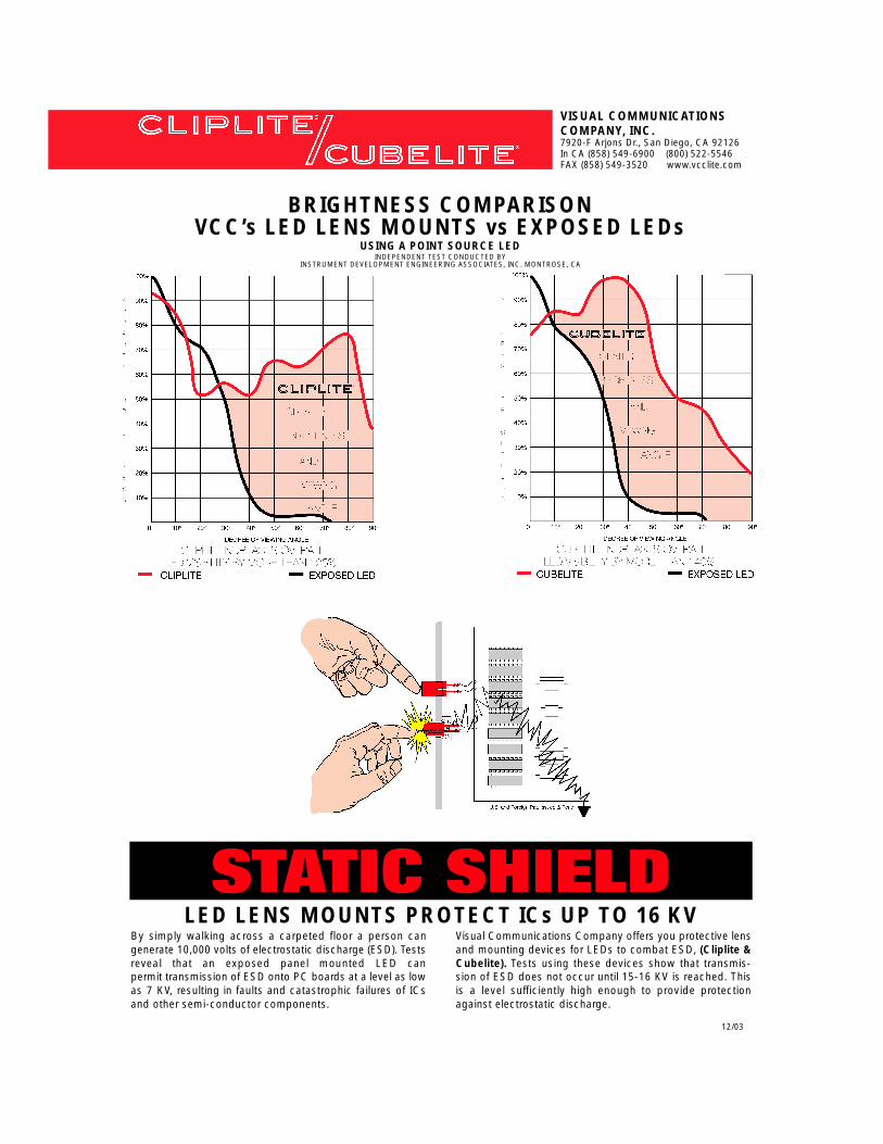
BRIGHTNESS COMPARISONVCC’s LED LENS MOUNTS vs EXPOSED LEDs
USING A POINT SOURCE LEDINDEPENDENT TEST CONDUCTED BY
INSTRUMENT DEVELOPMENT ENGINEERING ASSOCIATES, INC. MONTROSE, CA
LED LENS MOUNTS PROTECT ICs UP TO 16 KVBy simply walking across a carpeted floor a person cangenerate 10,000 volts of electrostatic discharge (ESD). Testsreveal that an exposed panel mounted LED can permit transmission of ESD onto PC boards at a level as lowas 7 KV, resulting in faults and catastrophic failures of ICsand other semi-conductor components.
Visual Communications Company offers you protective lensand mounting devices for LEDs to combat ESD, (Cliplite &Cubelite). Tests using these devices show that transmis-sion of ESD does not occur until 15-16 KV is reached. Thisis a level sufficiently high enough to provide protectionagainst electrostatic discharge.